Article

Acoustic-Based Machine Main State Monitoring for High-Speed CNC Drilling

by
Pimolkan Piankitrungreang
1,
Kantawatchr Chaiprabha
1,
Worathris Chungsangsatiporn
1,
Chanat Ratanasumawong
1,
Peemdej Chancharoen
2 and
Ratchatin Chancharoen
1,*
1
Department of Mechanical Engineering, Faculty of Engineering, Chulalongkorn University, Bangkok 10330, Thailand
2
Department of Computer Engineering, Faculty of Engineering, Chulalongkorn University, Bangkok 10330, Thailand
*
Author to whom correspondence should be addressed.
Machines 2025, 13(5), 372; https://doi.org/10.3390/machines13050372
Submission received: 5 February 2025 / Revised: 25 April 2025 / Accepted: 27 April 2025 / Published: 29 April 2025
(This article belongs to the Section Robotics, Mechatronics and Intelligent Machines)

Abstract

:
This paper introduces an acoustic-based monitoring system for high-speed CNC drilling, aimed at optimizing processes and enabling real-time machine state detection. High-fidelity acoustic sensors capture sound signals during drilling operations, allowing the identification of critical events such as tool engagement, material breakthrough, and tool withdrawal. Advanced signal processing techniques, including spectrogram analysis and Fast Fourier Transform, extract dominant frequencies and acoustic patterns, while machine learning algorithms like DBSCAN clustering classify operational states such as cutting, breakthrough, and returning. Experimental studies on materials including acrylic, PTFE, and hardwood reveal distinct acoustic profiles influenced by material properties and drilling conditions. Smoother sound patterns and lower dominant frequencies characterize PTFE drilling, whereas hardwood produces higher frequencies and rougher patterns due to its density and resistance. These findings demonstrate the correlation between acoustic emissions and machining dynamics, enabling non-invasive real-time monitoring and predictive maintenance. As AI power increases, it is expected to extract in-situ process information and achieve higher resolution, enhancing precision in data interpretation and decision-making. A key contribution of this project is the creation of an open sound library for drilling processes, fostering collaboration and innovation in intelligent manufacturing. By integrating big data concepts and intelligent algorithms, the system supports continuous monitoring, anomaly detection, and process optimization. This AI-ready hardware enhances the accuracy and efficiency of drilling operations, improving quality, reducing tool wear, and minimizing downtime. The research establishes acoustic monitoring as a transformative approach to advancing CNC drilling processes and intelligent manufacturing systems.

1. Introduction

The rapid advancement of artificial intelligence (AI) and increasing computational power has revolutionized various industries, including machining and manufacturing. The integration of AI-driven control systems and real-time data analysis has enabled machines to achieve higher precision, efficiency, and adaptability [1]. As sensor and actuator technologies continue to evolve, traditional CNC machines can be transformed into intelligent, AI-ready systems capable of self-optimization and autonomous decision-making [2].
This project investigates classical CNC drilling, where achieving high-quality hole formation depends on configuring key parameters such as feed rate and spindle speed. Given the irreversible nature of drilling, real-time monitoring and control are essential for optimizing performance and ensuring process stability [3]. Acoustic emissions generated during drilling provide a valuable source of data, as the mechanical forces involved in material removal create characteristic sound waves that propagate omnidirectionally [4]. By capturing and analyzing these acoustic signals, the system can monitor in situ machining conditions and adjust parameters dynamically for improved results.
In this context, acoustic monitoring emerges as a powerful tool for understanding machining dynamics, offering insights into tool wear, cutting conditions, and process anomalies [5]. This study integrates AI and big data techniques to analyze acoustic emissions [6], enabling the identification of critical drilling events such as tool engagement, breakthrough, and withdrawal. The use of AI in real machine operations necessitates adherence to physical laws during execution, leading to the concept of physical AI, which blends traditional physics-based approaches with deep learning methodologies. However, a significant research gap exists in applying deep learning techniques to this domain, particularly in the need for large datasets and real-time signal processing for machine correction.
The data-driven approach supports the development of predictive maintenance models and automated state detection algorithms, enhancing operational efficiency and safety in high-speed CNC drilling environments [7,8]. A key aspect of this research is the hardware architecture designed to convert conventional CNC machines into AI-ready systems. The proposed decentralized structure integrates a distributed communication protocol, edge computing capabilities, and acoustic sensors to facilitate intelligent monitoring [9].
Furthermore, the collaborative sharing of acoustic data fosters innovation in the research community. Open sound libraries and shared datasets allow engineers to benchmark algorithms and refine methodologies without the need for redundant experimental setups [1]. By leveraging this framework, acoustic monitoring continues to evolve, driving improvements in machine health monitoring, anomaly detection, and adaptive process control [10,11].
This paper focuses on the main state monitoring of drilling processes using acoustic signals, establishing a framework for capturing, processing, and analyzing these signals to enhance the understanding of drilling dynamics [12,13]. The goal is to improve process performance, reduce tool wear, and minimize downtime, ultimately contributing to broader advancements in intelligent manufacturing and precision engineering [14,15].

2. State of the Art

2.1. AI-Driven Process Optimization for CNC Drilling Machines in Industry 4.0

Drilling machines, as integral components of modern manufacturing systems, have evolved significantly in the era of Industry 4.0. Industry 4.0 emphasizes intelligent, interconnected, and automated production systems, and CNC drilling machines have become pivotal in this transformation. These machines now integrate advanced technologies such as IoT, AI, and big data analytics, enabling in-situ process monitoring and adaptive process control.
One of the key features of drilling machines in Industry 4.0 is their capability for machine health monitoring and in-situ process monitoring. By continuously analyzing data from multiple sources, including acoustic signals and vibration sensors, the system detects abnormalities and monitors behavior to prevent breakdowns [16]. Such systems rely on edge computing and localized intelligence to process data efficiently and respond to deviations in real time. Additionally, digital twins, virtual replicas of physical machines, are employed for predictive maintenance, simulating operational conditions and enabling proactive condition-based maintenance. This minimizes downtime and extends the lifespan of the machinery [17,18]. Human–machine collaboration is another hallmark of Industry 4.0 drilling systems. These machines are designed with a flexible and modular architecture, allowing for multi-material handling and adaptability to various manufacturing requirements. Advanced human–machine interfaces, equipped with microphones, speakers, cameras, and projectors enable intuitive control and monitoring, ensuring seamless collaboration between operators and automated systems, as illustrated in Figure 1. Remote monitoring and control further enhance productivity by allowing operators to oversee operations from anywhere, leveraging IoT and cloud-based systems [19].
The manufacturing process itself benefits greatly from these advancements. During the design and conceptualization phase, smart technologies [20] and AI-driven tools optimize material selection and production planning. CNC drilling machines execute the operations with unparalleled precision, ensuring high-quality results during manufacturing, quality control, and finishing stages. By utilizing edge AI, these machines achieve localized intelligence, enabling quick adjustments based on real-time feedback [21]. For instance, during drilling operations, sensors monitor parameters such as cutting force, spindle speed, and vibration, and actuators adapt the process dynamically to maintain consistent output quality. This ensures not only precision but also sustainability by reducing waste and energy consumption [22].
In conclusion, drilling machines in Industry 4.0 represent the convergence of smart technologies, IoT, and cyber-physical systems. By incorporating machine health monitoring, digital twins, adaptive control, and human–machine collaboration, these systems enhance manufacturing efficiency and flexibility. The integration of AI, big data [23,24], and advanced sensors positions CNC drilling machines as essential assets in modern production environments, delivering high-quality results while meeting the demands of dynamic industrial ecosystems.

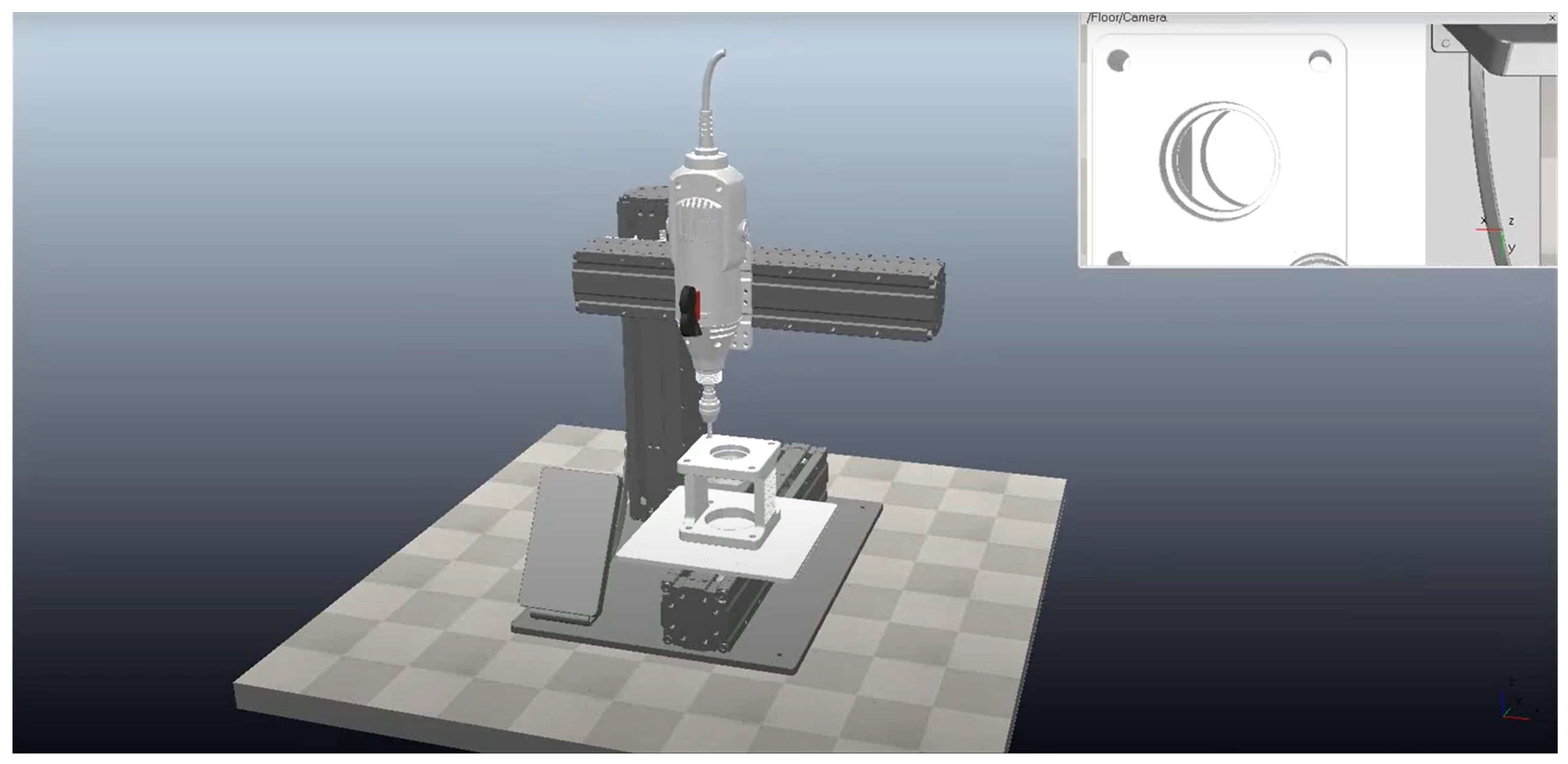
2.2. Real-Time Data Integration and Simulation in CNC Drilling

The concept of digital twins has revolutionized the manufacturing industry by providing a virtual replica of physical systems, enabling advanced monitoring, simulation, and optimization capabilities [25]. In the context of CNC drilling machines, digital twins serve as a pivotal tool for improving precision, efficiency, and reliability. By integrating real-time data, simulation models, and predictive analytics, digital twins enhance the overall performance and reduce risks associated with drilling operations [26].
As shown in Figure 2, a digital twin for a CNC drilling machine replicates its physical counterpart virtually, encompassing every aspect of the machine, including its mechanics, electronics, and control systems. Virtual testing within the digital twin environment allows manufacturers to simulate and validate drilling operations, toolpaths, and machine behaviors before actual implementation. This reduces errors, minimizes material waste, and ensures that the physical machine operates at optimal performance levels. For instance, the digital twin can simulate multi-axis precision movements, enabling the identification of potential deviations in toolpath and hole position before actual machining begins [27]. One of the primary advantages of digital twins is real-time data integration. By utilizing sensors and IoT devices, real-time operational data from the CNC drilling machine is fed into the digital twin, enabling live monitoring and controlling [28]. These data include spindle speed, cutting forces, tool wear, and machine vibrations, which are continuously analyzed within the digital environment. The correlation between the digital twin and the drilling process ensures that the virtual model reflects the actual machine’s conditions accurately, enabling dynamic adjustments to maintain precision and stability [29].
Simulation and modeling capabilities further enhance the digital twin’s functionality. Predictive analytics, powered by machine learning algorithms [30,31], identify trends and anomalies in the drilling process, offering insights into potential tool wear, misalignment, or operational inefficiencies. Moreover, optimization algorithms embedded in the digital twin refine drilling parameters such as feed rate, spindle speed, and toolpath to maximize efficiency and accuracy. Vision systems integrated with the digital twin provide an additional layer of precision by capturing high-resolution images of the machining process [32]. These systems validate hole positions, surface finish, and tool alignment in real time, ensuring consistent quality and reducing rework. The digital twin’s ability to simulate and monitor hole creation processes aligns with the physical machine, allowing for precise correlation between virtual and physical outputs. The low-risk nature of digital twin implementations makes it a valuable asset for manufacturers [33]. By conducting virtual testing and optimizing processes within the digital environment, manufacturers can ensure that physical operations are carried out with minimal errors and maximum efficiency.
In conclusion, the digital twin concept for CNC drilling machines combines advanced technologies such as real-time data integration, simulation, predictive analytics, and vision systems to enhance precision, efficiency, and reliability. By providing a virtual environment for testing, monitoring, and optimization, digital twins minimize risks, improve toolpath accuracy, and ensure high-quality drilling outcomes [34].

3. Materials and Methods

3.1. Integrating Acoustic Wave and Mechanical Analysis

Drilling is a fundamental machining process in creating inner cylindrical surfaces which can be used to create precise holes in a specimen by utilizing a rotating drill bit. The quality of drilling is influenced by several factors, including the feed rate, spindle speed, and tooling condition. During the process, these factors must be controlled, the specimen must be securely clamped, and heat buildup must be monitored and minimized to ensure the quality of the drilled hole and to limit adverse effects on tool life.
In addition to mechanical considerations, the mechanical vibrations that occur during the drilling process are propagated as sound waves, as shown in Figure 3. The material properties of the workpiece and the interaction between the drill bit and the workpiece both influence how sound waves are produced [35]. These acoustic waves carry valuable information about the operational state of the machine [18,36], and are characterized by their frequency spectrum, amplitude, and energy. Analyzing the frequency spectrum helps identify the operational state and detect anomalies such as tool wear or potential tool breakage.
By combining mechanical and acoustic analysis, parameters such as feed rate, spindle speed, drill bit condition, and operational state can be identified and used for real-time optimization to achieve high precision and consistent quality in workpieces. Acoustic signals are also leveraged in real-time monitoring systems to detect critical events, such as tool wear, enabling predictive maintenance and reducing machine downtime [12]. These innovations not only improve the reliability of the automated drilling process but contribute to the broader application of intelligent industrial machining systems [4,13].

3.2. Acoustic Wave Propagation in Drilling Process

When a machine operates, the forces acting on its components are often periodic/cyclic, meaning they repeat over time. A typical representation of such a force is given by:
F t = F 0 + F 1 C 2 π f t
where F is a summation of force, F0 is constant force, F1 is amplitude of cyclic force, and C is a cyclic function that describes the periodic nature of the force as a function of frequency (f). A summary of the mathematical variables used in this analysis is provided in Table 1.
The cyclic function can be expressed as a sum of sinusoids (Fourier’s expansion):
C 2 π f t = n = 1 N A n sin 2 π f n t + ϕ n
A force can create the surface of displacement in periodic motion by
m u ¨ + c u ˙ + k u = F t
where m, c, and k are the mass, damping coefficient, and stiffness of the system, respectively, and u(t) is the displacement of surface. These surface vibrations, governed by Equation (3), generate acoustic waves that propagate through the surrounding medium.
These acoustic waves contain crucial information about the machine, as they are generated throughout the machine’s operation. During the drilling process, the interaction between the drill bit and the workpiece produces a variety of acoustic signals that reflect key characteristics of the operation. Variations in the acoustic waves can provide insights into parameters such as spindle speed, feed rate, and tool wear.
The effect of attenuation raises concerns about the integrity of the transmitted information. A simple model of attenuation can be expressed as:
P x , t = P 0 e α x cos 2 π f t + ϕ
where P(x,t) is the pressure of the sound wave at position x and time t, P 0 is the maximum amplitude of the pressure at the source, α is the attenuation coefficient, which quantifies the rate of energy loss per unit distance traveled by the wave, x is the distance the wave has traveled through the medium, f is the frequency of the sound wave and ϕ is the phase of the wave. Notably, the attenuation effect depends on frequency, with higher frequencies experiencing greater attenuation. While the amplitude of the pressure wave decreases due to attenuation, its frequency remains constant. This property allows Fourier transforms to be used for extracting data from the sound wave, enabling the assessment of machine conditions.
In conclusion, the periodic forces acting on a machine during operation generate mechanical waves. The force acting on the machine can be expressed as a combination of constant and cyclic components, with the cyclic part representing periodic motion that corresponds to a specific frequency. As the sound waves propagate through the surrounding medium, they experience attenuation, but the frequency of the acoustic wave remains largely intact, providing a stable characteristic of the underlying machine operation. By measuring the acoustic pressure at different points and analyzing the frequency components of the sound waves, we can effectively detect the cyclic force frequencies in the machine. This allows for non-invasive in-situ monitoring of machine performance, enabling the detection of irregularities, wear, or degradation in the system.
In the context of spindle drilling, the torque ( τ ) required to maintain the spindle’s operation is given by (dc motor equation):
τ m = K i V K v   ω R
where τ m is the torque, K i is a constant related to the system’s characteristics, R is resistance in motor, V is the input voltage, K v is a constant of motor and ω is the angular velocity of the spindle.
The rotational dynamics of the spindle can be modeled by the following equation of motion, considering both the inertia and damping of the system.
J ω ˙ + c ω = τ m τ r
The presence of the resistance torque τ r in the equation reflects the effect of the drilling process on the spindle’s motion. When the drill is not cutting through the material, τ r is zero, indicating no resistance, and the spindle operates normally. However, when drilling is taking place, τ r becomes positive, representing the additional resistive force generated by the material being drilled. As τ r increases, the angular velocity ω of the spindle decreases, which in turn affects the rotational speed of the spindle motor. Since the sound frequency generated by the spindle is directly related to the rotational speed, a reduction in ω leads to a decrease in the frequency of the sound waves produced by the spindle motor. This decrease in frequency can be detected through acoustic monitoring. Therefore, by analyzing the changes in the sound frequency, we can infer the presence and magnitude of τ r , providing a reliable method for detecting the occurrence of drilling and monitoring the operation conditions of the machine in real time [37].

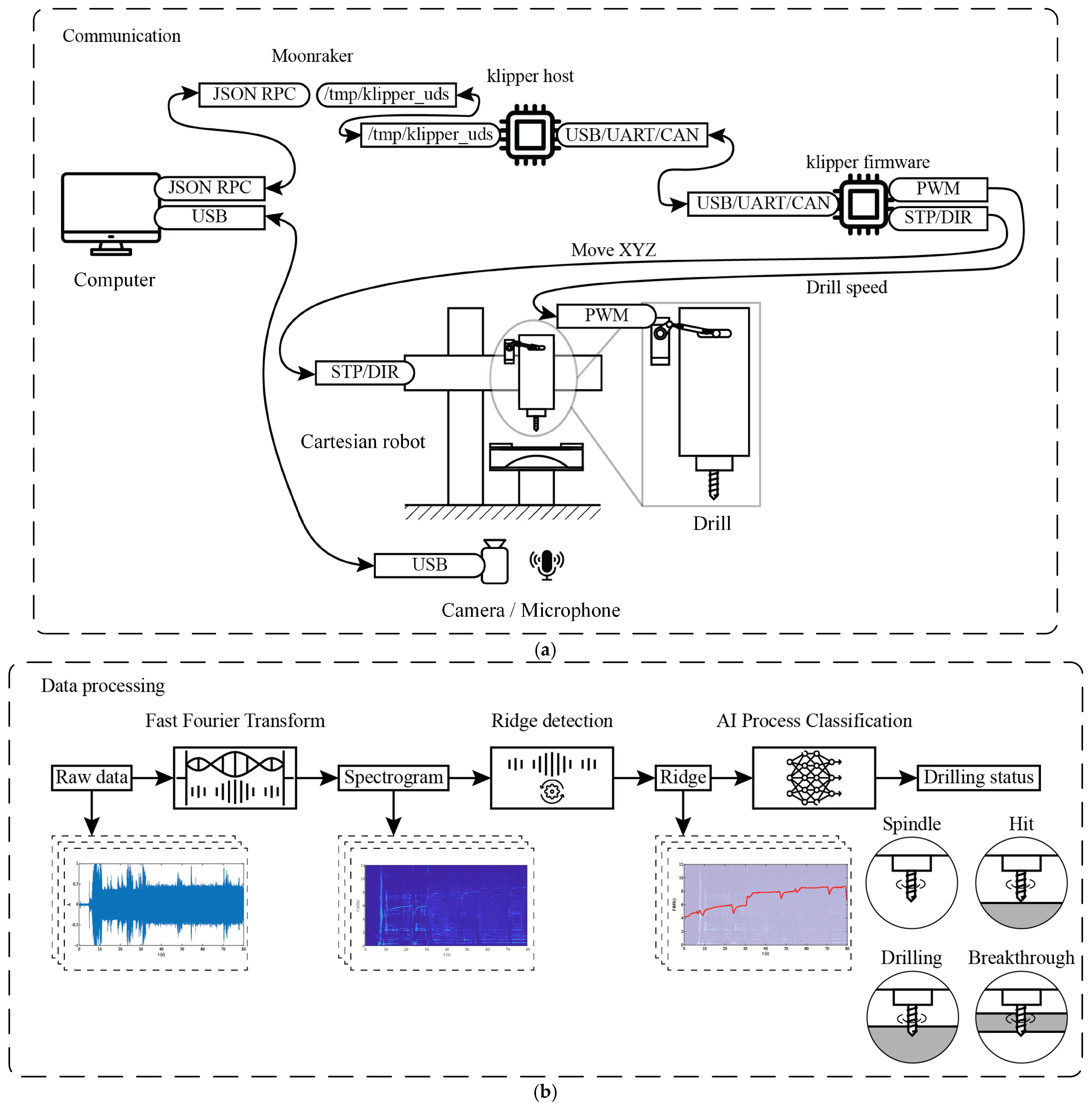
3.3. Optimizing CNC Drilling Performance with Klipper and AI-Enhanced Data Processing

Figure 4a illustrates the architecture of the proposed CNC drilling hardware, which is designed to provide high precision, adaptability, and efficiency through the integration of advanced communication protocols, robust control systems, and data processing capabilities. To create AI-ready environments, the software and firmware of the machine need to be distributed and decentralized. These characteristics are necessary to ensure scalability, flexibility, and real-time processing, allowing the system to seamlessly integrate with AI technologies and adapt to evolving requirements. At the core of the system is Klipper, a decentralized 3D printer firmware [38]. Traditional firmware [39,40] localizes the system onto a single microcontroller, whereas Klipper enables distributed operation across multiple microcontrollers. Note that Klipper requires a host (master) running on a computer. Such distribution enhances the efficiency of high-speed spindle operations and allows fine control in real time over motor power and speed adjustments, while the host on the computer handles computationally intensive and non-real-time tasks such as AI inference. Another crucial benefit of Klipper is its network connectivity via Moonraker, a web API server. This connectivity unlocks the potential for further decentralized hardware, cloud computing and big data applications. Figure 4a depicts the connectivity between the Klipper host and another edge computer, enabling the reception, handling, and processing of acoustic signals efficiently.
The hardware employs a Cartesian robot framework, ensuring precise multi-axis motion control suitable for complex machining tasks and 3D printing compatibility [36]. Operators can customize G-code [41,42], for tailored operations, enabling flexibility in managing power, motion, and cutting paths. The user interface, connected via Moonraker, provides an intuitive platform for real-time monitoring and parameter adjustments, ensuring seamless integration between hardware and software components.
Figure 4b illustrates the data processing workflow, which begins with the collection of raw sensor data and is analyzed across both time-domain and frequency-domain representations. Time-domain analysis captures transient events such as spindle engagement, material contact (hits), drilling progress, and breakthroughs. Visualizations such as spectrograms and color mapping highlight variations in intensity, making it easier to detect anomalies. Frequency-domain analysis, achieved through Fast Fourier Transform [13], identifies critical frequency bands associated with machining states, such as chatter, tool wear, or cutting inefficiencies. Advanced signal processing techniques like ridge detection [43] are used to track dominant frequencies and parameterize the machining process in real time.
To further enhance performance, the system incorporates AI-driven classification techniques for identifying drilling states and optimizing operations [35]. A density-based clustering algorithm called DBSCAN [4] is applied to cluster signal patterns, correlating them with specific events including spindle speed, tool engagement, and material breakthroughs. This reduces the dependency on labeled datasets and enables accurate classification of operational states. Parameters such as spindle speed, vibration intensity, and tool engagement are continuously monitored to determine the current drilling status, allowing for real-time adjustments to improve outcomes.
The user interface ties these elements together, offering a comprehensive display of processed data, including time-domain signals, spectrograms, frequency-domain analyses, and clustering results. Operators can easily adjust spindle speeds, motor power, and G-code parameters to optimize performance based on specific task requirements. By combining advanced communication, precise control systems, sophisticated data processing, and AI-based classification, this architecture provides a state-of-the-art solution for CNC drilling.

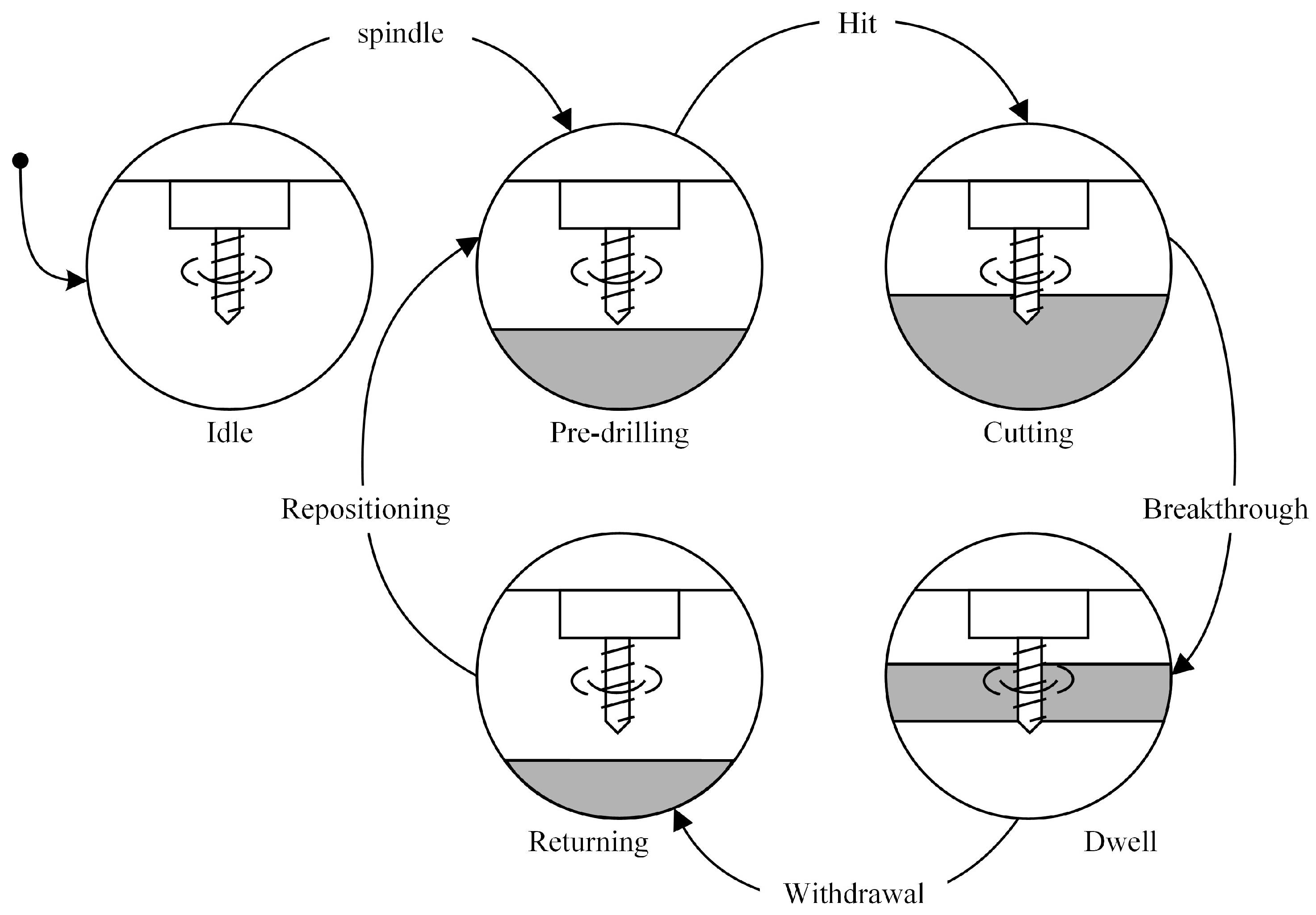
3.4. Finite State Machine Approach to Drilling Automation

In the machining process, various drilling operations are employed, including through-holes, interrupted cuts, peck drilling, countersinking, and counterboring, each serving distinct applications and offering specific advantages. These processes are often controlled using canned cycles, which are pre-programmed sequences designed to automate and streamline the drilling operation. Each drilling cycle exhibits unique operational behaviors, resulting in varying acoustic characteristics. This study focuses on the through-hole drilling process due to its simplicity and its well-defined cutting phases. Through-hole drilling involves a stable cutting phase, initiated by a hit and followed by a breakthrough event. The steady cutting phase provides an opportunity to analyze drilling parameters such as spindle power and feed rate, as they interact with the material. The hit and breakthrough event, driven by physical interaction, is of particular interest as it presents a distinct and observable shift in the drilling dynamics.
The drilling process can be effectively modeled using a finite state machine (FSM) to automate operations, monitor performance, and control processes, while also addressing error handling and safety concerns [1]. In acoustic-based state monitoring, predictions are typically expressed in terms of probability. An FSM not only defines state but also concretely defines state transition. Such an FSM can enhance predictions by promoting states that are likely to be transited to and inhibiting those that are not. This approach prevents physically impossible behaviors and provides more accurate results by linking digital processing with physical behavior.
Figure 5 illustrates the FSM design, which divides the drilling process into five distinct states: Idle, Pre-Drilling, Cutting, Dwell, and Returning [44]. Transitions between these states are governed by specific events and conditions, ensuring precise control and efficient operation. The process begins in the Idle state, where the system waits for a command to initiate drilling. Once triggered by a spindle command, the spindle activates, and the drill bit moves toward the workpiece, entering the Pre-Drilling state. When the drill bit makes initial contact with the workpiece, the machine transitions to the Cutting state. The spindle continues penetrating until the drill bit emerges beyond the lower surface, causing a breakthrough. At this point, the process moves to the Dwell state, where the drill bit stops advancing downward but continues rotating to ensure hole quality. After the dwell time elapses, the machine enters the Returning state, withdrawing the drill bit to a free-space area before transitioning back to Pre-Drilling for repositioning.
The drilling process is governed by the proposed state machine, which can be integrated with acoustic analysis to enhance machine state estimation [45]. Additionally, error handling can be embedded within the FSM to detect anomalies such as excessive vibration, tool wear, or material misalignment. Automation ensures smooth state transitions, minimizing manual intervention and improving efficiency while maintaining stringent safety conditions. The system is AI-ready, with hardware designed to integrate future AI advancements. As AI evolves, it will enable real-time process optimization, anomaly detection, and predictive maintenance, making the system increasingly autonomous and intelligent.

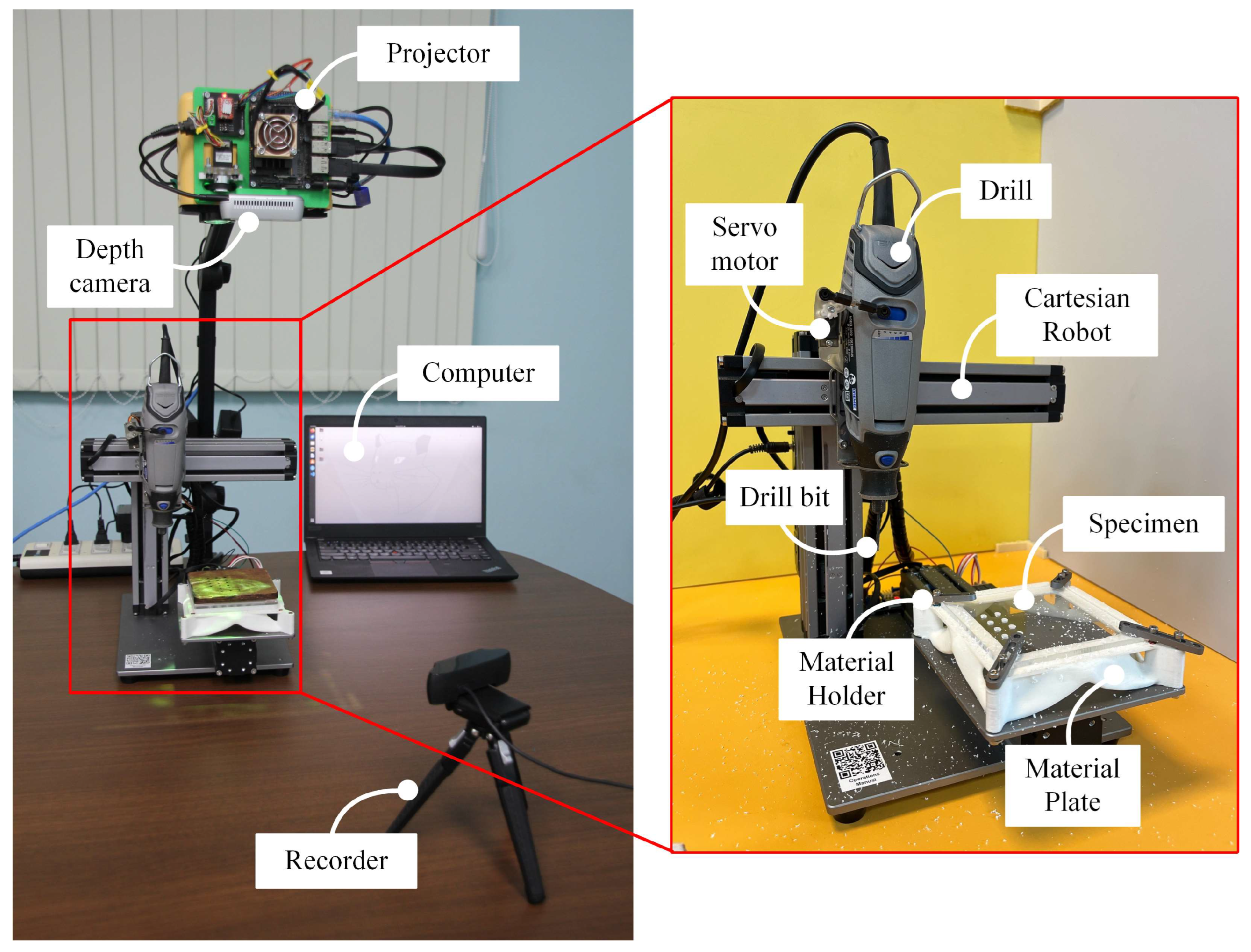
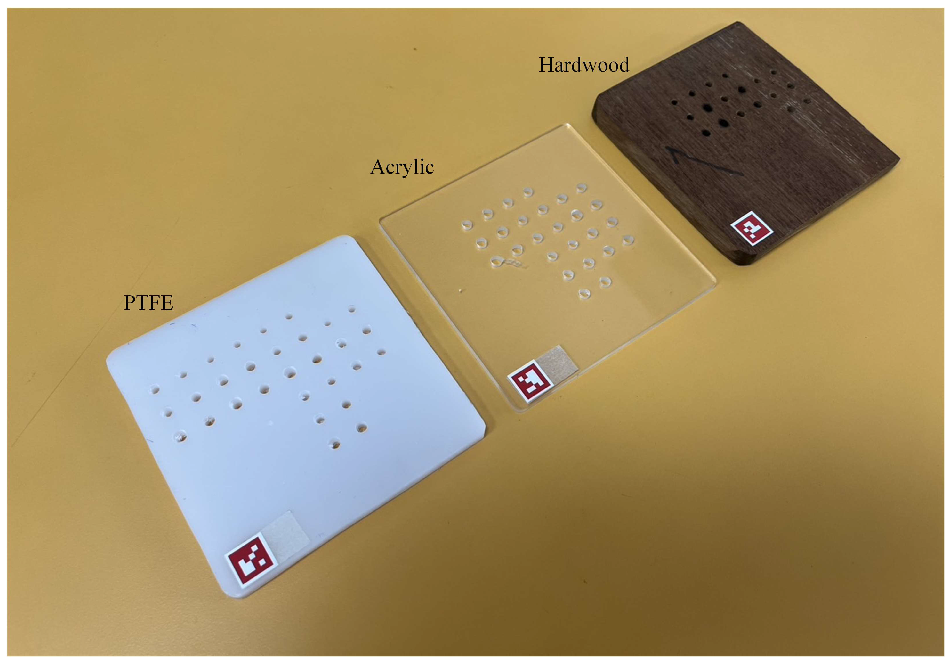
3.5. Experimental Setup

The experimental setup for this study employs a high-speed CNC drilling machine integrated with acoustic sensors to capture pressure waves during the drilling process. The high-speed spindle ensures precise drilling that accurately replicates real industrial applications, while the reliable robotic stage with digital twin enables precise validation of the machine’s state throughout the experiment. This setup facilitates continuous monitoring of the drilling process and enables the detection of key operational events, providing valuable insights into machine performance and process dynamics.
Figure 1 illustrates the demonstration setup of the high-speed CNC drilling machine used for machine state monitoring. The high-speed drill is realized by a Dremel 3000-1/25 rotary tool, fitted with a 2.4 mm diameter high-speed steel drill bit. This drill allows for adjustable power input, enabling control variations in drilling conditions. This configuration ensures sub-millimeter precision, enhancing state analysis and validation through controllable positioning [46]. Automated control is essential for large-scale data experiments, and thus, the drill is attached by a slider–crank mechanism coupled with a servo motor. This system allows for automatic adjustment of the drilling power throughout the experiment, ensuring optimal performance and flexibility.
To validate the accuracy of the state predictions, the digital twin concept, as illustrated in Figure 2, was employed. The digital twin was constructed using CoppeliaSim (with the Bullet physics engine) and MATLAB R2024a (Version 24.1.0) for multibody simulation. The digital twin can be controlled using the same commands as the physical experiment. This approach enables the system to be re-executed alongside the captured acoustic wave data. By comparing the predicted states with the actual states from the digital twin, a more accurate assessment of the model’s performance can be made [47].
For pressure wave measurements, this study focuses on the human-audible spectrum, as it aligns with many existing acoustic sensors and promotes seamless integration with human–machine interaction [48]. During the drilling process, various events occur, making it essential to capture synchronized acoustic and visual data for accurate analysis. To achieve this, a Logitech C930e recorder was chosen, positioned 300 mm from the machine, facing toward it. The measurements were taken with a sampling rate of 48,000 Hz and 16-bit resolution. The pressure wave data were then analyzed using MATLAB and Short-Time Fourier Transform with a time resolution of 100 ms. The recorder also provides high-quality image capture and can be synchronized with the acoustic measurements, ensuring reliable, real-time monitoring of both the acoustic emissions and visual data throughout the experiment, thereby enhancing the overall accuracy of the analysis.
The experiment focused on a through-hole drilling operation, examining three key parameters: feed rate, drilling power, and material type. For each material, six drilling attempts were conducted. The feed rate was controlled by a z-axis actuator on the Cartesian stage, adjusting to 50 and 150 mm/min during cutting. The drilling power was input by varying the level of the rotary tool to 60, 80, and 100 W. With this power input setup, the drill responds dynamically to each material’s reaction, reflecting its unique characteristics. Material selection was based on their distinct mechanical properties, such as ductility, brittleness, and homogeneity. The experimental drilling process was conducted on three materials: acrylic (3 mm), PTFE (5 mm), and hardwood (10 mm). Acrylic was chosen to represent a brittle material, whereas PTFE, known for its ductility, low friction coefficient, and flexible behavior, served as a contrast with more uniform characteristics. Both acrylic and PTFE exhibit homogeneous properties, while hardwood, with its layered structure and varying grain patterns, represents a non-homogeneous material. This diversity in material properties provides valuable insights into how different structural characteristics impact the drilling acoustic characteristics.
While this work presents the implementation of a digital twin using CoppeliaSim and MATLAB for simulation and analysis, it does not include experimental validation against real machine data. Validation of the digital twin is beyond the scope of this study and will be addressed in future work.

4. Results

4.1. Acoustic Characteristics of Materials Drilling

Acoustic signals during drilling are depicted in Figure 6. These signals contain rich information but can be difficult to interpret. However, spectrogram visualization and waveform analysis provide better readability. To achieve this, the acoustic signal was transformed using the Short-Time Fourier Transform. The spectrogram results revealed distinct patterns corresponding to specific drilling stages. A green line in the spectrogram indicated the tool’s initial contact with the material, while a pink line represented the breakthrough phase. The experiment began with a power level of 60 W and a feed rate of 50 mm/min, with these parameters increased sequentially.
The acoustic spectrogram effectively highlighted key characteristics, which varied based on the drilling parameters and material properties. In this study, only the most prominent dominant patterns were used to guesstimate the process state. The frequency spectrum analysis identified distinct dominant frequencies and amplitude spikes, reflecting the solid and brittle nature of acrylic. The material’s sharp and brittle properties produced noticeable sound wave patterns, including sound spikes and clearly defined frequencies in the spectrogram. Changes in power and feed rate influenced the acoustic signature, revealing the effects of drilling parameters on sound signals. Pattern recognition techniques were applied to identify consistent sound wave features associated with specific drilling conditions [49]. For example, increasing power levels resulted in higher amplitude and slightly higher frequency signals, while faster feed rates caused shifts in dominant frequencies. These variations were attributed to the interaction between the drill bit and the acrylic material, emphasizing how material characteristics influence sound wave generation.
As observed in Figure 6, the spectrogram illustrates its correlation with the drilling operation. At t = 31, 54 s, an increase in power corresponds to a frequency increase. According to Equation (5), a rise in power leads to a higher rotational speed of the drill ( ω ), which strongly correlates with the frequency observed in the spectrogram. When the drill enters the cutting state, the frequency decreases due to higher resistive torque ( τ r ) from material cutting, which lowers the rotational speed ( ω ). As described by Equation (6), the resistive torque ( τ r ) alters the drill’s dynamics, which is reflected in the frequency variations in the spectrogram.
The spectrogram reveals a dominant ridge whose temporal behavior aligns with the characteristics of a first-order dynamic system. Specifically, the ridge gradually rises following the application of voltage ( V ) and stabilizes once the steady-state rotational speed (ω) is achieved. This rise pattern mirrors the expected response of a spindle motor subjected to a step input. Furthermore, the ridge shows a recovery in frequency after the drill breakthrough the material, indicating fading in resistive torque ( τ r ). These observations strongly suggest that the spectrogram captures the dynamic response of the spindle motor itself and underlines the relationship between acoustic features and the motor’s mechanical behavior during different phases of drilling.
Building on this interpretation, the experimental result demonstrated a clear correlation between acoustic signals and drilling conditions. The spectrogram analysis provided valuable insights into the drilling process, enabling the identification of critical events such as tool hits and breakthroughs. These findings highlight the potential of using acoustic monitoring as a non-invasive method for real-time process control and quality assurance in drilling operations.
The second experimental drilling was conducted on a 5 mm thick PTFE (Polytetrafluoroethylene) specimen and as in the acrylic drilling test, The results were analyzed through frequency spectrum, amplitude, and pattern recognition, highlighting key differences due to the unique material properties of PTFE. In Figure 7a, the drilling process is shown, conducted under different power and feed rate conditions, akin to the first experiment, to assess their impact on the acoustic response.
The frequency spectrum analysis for PTFE revealed lower dominant frequencies compared to the acrylic. The soft and ductile characteristics of PTFE led to continuous chip formation, producing smoother and less abrupt sound signals. The amplitude of the signals was generally lower, reflecting reduced resistance encountered by the drill bit while cutting through PTFE. Unlike acrylic, where sharp and brittle behavior caused sound spikes, PTFE generated a more consistent and smoother acoustic profile. Adjusting power levels and feed rates resulted in distinct acoustic patterns. At low feed rates and high power, the drilling process produced smooth sounds due to PTFE’s low friction properties and ductile nature. The absence of sharp transitions in chip formation minimized noise spikes and created a steady acoustic signature. Conversely, noise levels increased slightly with higher feed rates, as the material’s ductility caused more pronounced deformation and vibration. The unique properties of PTFE, including its softness and low friction, directly influenced the sound wave characteristics during drilling. Pattern recognition techniques highlighted these attributes, enabling the identification of distinct acoustic signatures that differed from the acrylic specimen. The smooth and low-noise acoustic profile of PTFE drilling serves as a contrast to the sharper and more intense signals observed in the acrylic test, providing insights into the material-specific behavior of sound waves during machining.
The PTFE drilling results demonstrated the impact of material properties on acoustic signals. The soft and ductile nature of PTFE, combined with low friction, produced smoother and more consistent sound waves with lower amplitude and dominant frequencies. These machining characteristics reflect lower resistive torque ( τ r ), allowing the spindle to maintain a more constant rotational speed (ω) during drilling, which results in a stable ridge frequency in the spectrogram. These findings reinforce the importance of acoustic monitoring in identifying material-specific drilling characteristics and optimizing machining parameters [50].
The last experimental drilling was conducted on a 10 mm thick hardwood specimen. This non-homogenous material exhibits unique acoustic properties compared to acrylic and PTFE. In Figure 7b, the frequency spectrum analysis for hardwood revealed higher dominant frequencies compared to acrylic and PTFE, reflecting the material’s high density and resistance to drilling. The amplitude of the signals was also higher, indicating increased cutting forces and vibrations. The dense nature of the material caused significant energy transfer during drilling, captured as high-intensity sound waves with distinct peaks in the frequency spectrum. Pattern recognition analysis highlighted consistent frequency bands corresponding to different drilling stages, providing insights into drill bit behavior. The high resistance during cutting generated pronounced vibrations, resulting in rougher acoustic patterns compared to PTFE drilling. Hardwood’s rough texture and high density contributed to these variations in sound waves. Adjustments in power and feed rate significantly altered acoustic characteristics. At higher power levels, increased spindle speed reduced some resistance effects, smoothing out portions of the signal. However, at low feed rates, the cutting process became more pronounced, amplifying vibrations and creating sharp peaks in the frequency spectrum. These variations underscore the importance of balancing power and feed rate for optimal drilling in high-density materials like hardwood. The unique features of hardwood, including its high resistance and vibration intensity, strongly influenced the acoustic signatures. The rough texture of the material added complexity to the sound waves, making them less uniform than those of softer materials like PTFE.
The hardwood drilling results showcase the challenges posed by high-density materials in terms of cutting resistance and vibration intensity. The frequency bands and amplitude spikes provide critical data for understanding the interaction between the tool and the material. This study emphasizes the need for precise parameter adjustments and acoustic analysis to achieve optimal performance and quality in drilling operations for hard materials.
In conclusion, the sound generated during the drilling process contains rich information about the dynamic nature of the drilling. The sound patterns align with the physics of the drilling process.

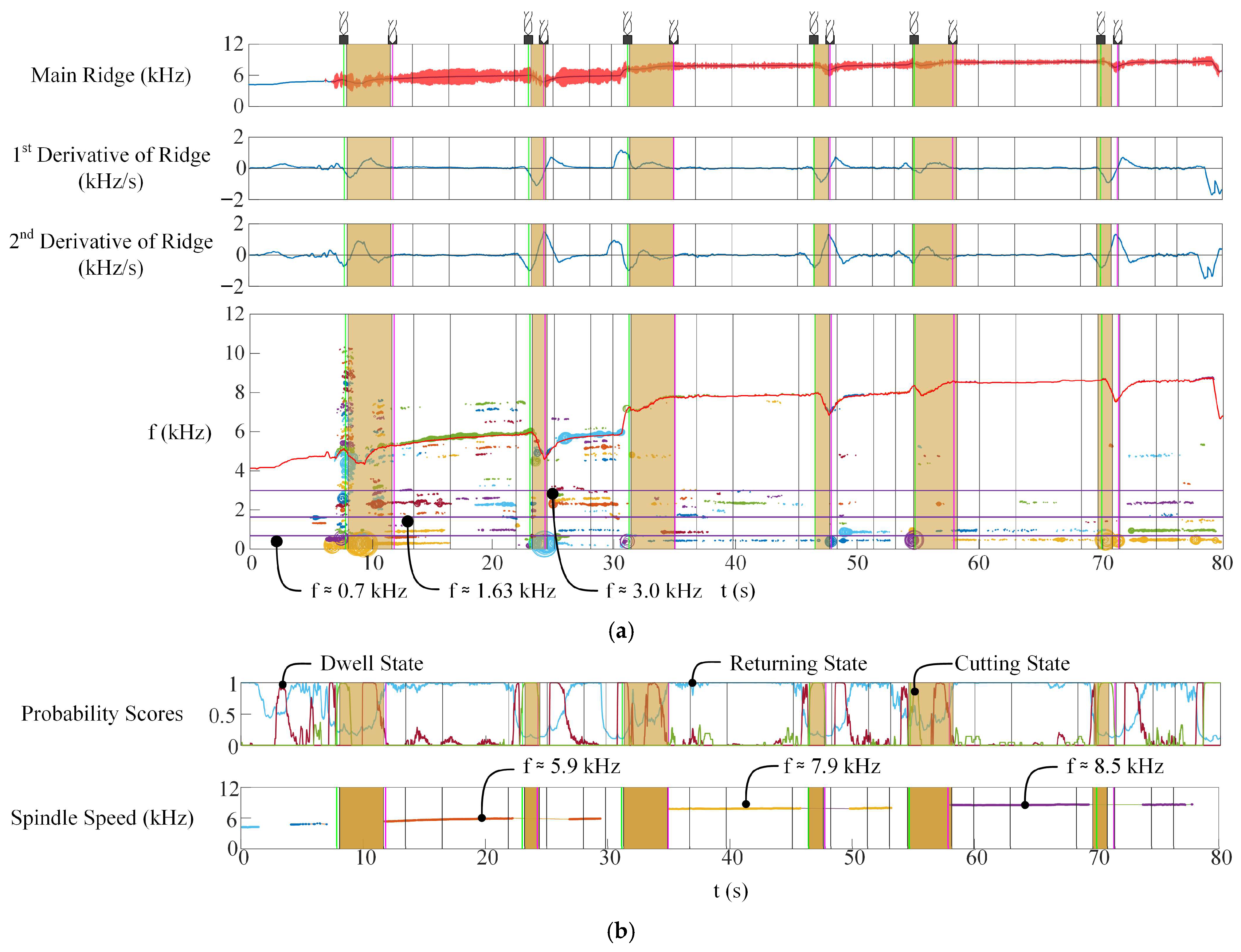
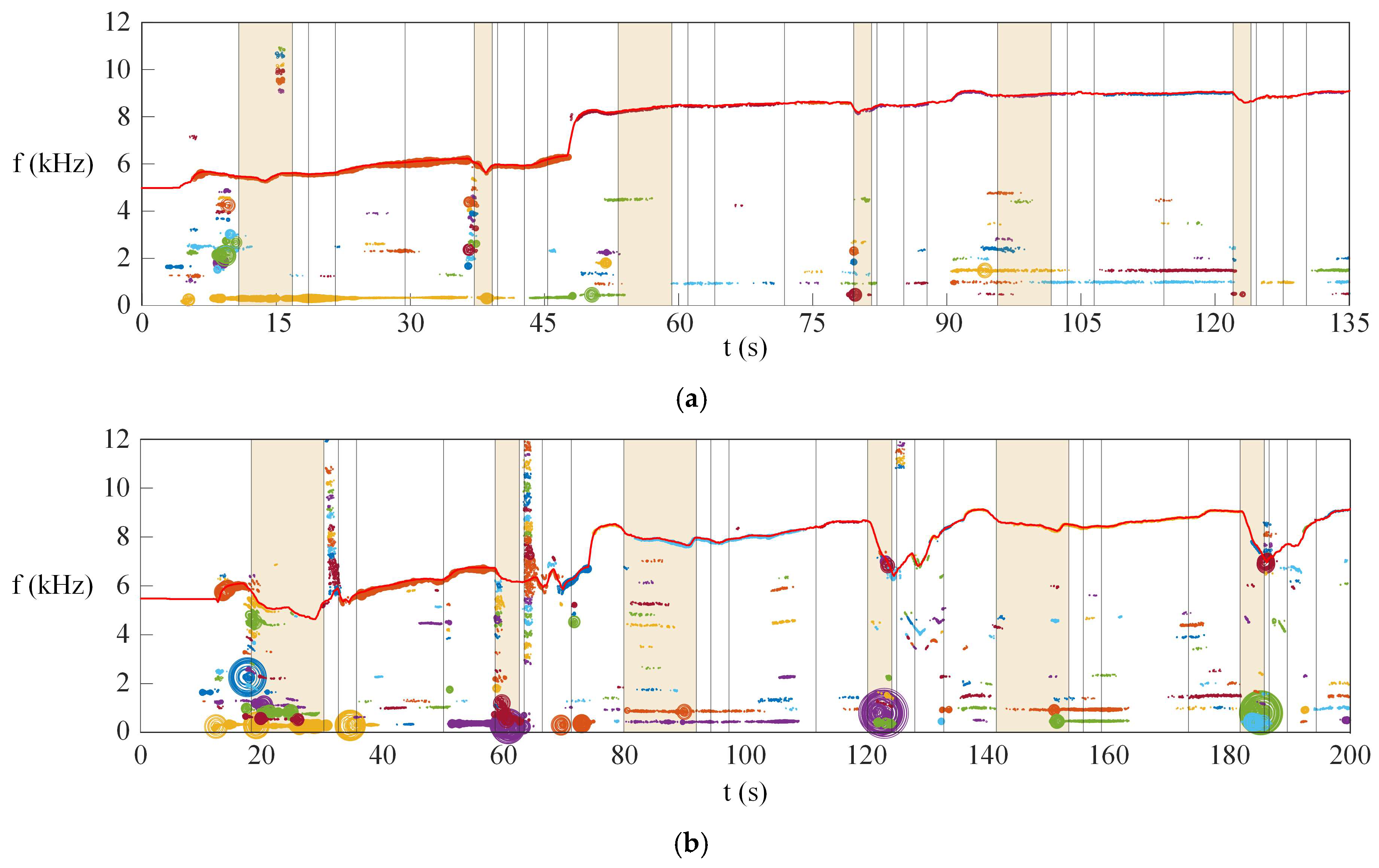
4.2. Analysis for Drilling Process Characterization

The data processing framework for drilling analysis utilizes big data concepts to manage and extract valuable insights from large volumes of acoustic data generated during machining. Advanced analytical techniques enable the extraction of meaningful information from rich acoustic signals.
Through this framework, the studied case categorizes three primary states: Cutting, Breakthrough, and Returning (which includes the Repositioning state). These states are determined by analyzing acoustic signals, which are processed to extract features such as frequency spectrum, amplitude, and signal patterns. The cutting state is characterized by stable, high-frequency signals associated with material removal, while the breakthrough state shows frequency spikes and amplitude variations as the drill bit penetrates through the material. The Returning state, on the other hand, exhibits reduced signal intensity and specific frequency changes as the drill bit withdraws from the hole.
Spindle power estimation further refines state detection, correlating power fluctuations with cutting resistance and tool interactions. This architecture connects acoustic, vibrational, and power data with actual drilling events, creating a relevant and comprehensive dataset. Event-based analysis is integrated to link clustering results to real-world phenomena, ensuring the identified states accurately reflect physical events like material engagement, penetration, and withdrawal. In conclusion, the combination of data clustering, intelligence, and big data integration provides a robust framework for estimating drilling process states and spindle power states. The use of DBSCAN enables the precise classification of cutting, breakthrough, and Returning states, while the system’s technical architecture ensures that data are directly tied to real-world events. This approach not only enhances process monitoring and decision-making but also supports predictive maintenance and optimization in advanced manufacturing environments.
Figure 8a illustrates the main ridge ( ϕ ), its derivative ( ϕ ˙ , ϕ ¨ ), and the peak frequency clusters observed during the experiment. Time-frequency ridge extraction was applied to the spectrogram using the MATLAB command tfridge, with a single ridge extraction and a penalty factor of 0.5 to identify the dominant frequency components. The derivative of the ridge was computed by taking the time derivative of the filtered main ridge signal. To enhance signal clarity and reduce noise, a moving average filter with a 0.5 s window was applied.
Since ridge extraction can be limited by the number of detectable ridges, an additional peak detection method was employed to extract other prominent peaks in the spectrum. These peak locations were then clustered using the DBScan algorithm, enabling a more comprehensive analysis of frequency distributions.
The main ridge frequency ranges from 6 to 10 kHz, with the y-axis representing frequency and amplitude displayed as a bar. Notable patterns are observed at approximately 700 Hz, 1630 Hz, and 3000 Hz, which are monitored. The amplitude of these frequencies is visualized using a bubble plot, with cyclic colors grouping data within the same cluster.
The analysis reveals a strong correlation between frequency components and the drilling process. High-amplitude frequencies at 700 Hz, 1630 Hz, and 3000 Hz are noticed during critical events, such as material breakthroughs or changes in cutting dynamics. These frequency patterns may be linked to the spindle rotation speed and material properties. Additionally, acoustic data visualization can provide insights into hole quality, detect chatter or excessive vibrations, and/or identify tool wear, misalignment, or other anomalies affecting the drilling process.
In Figure 8b, drilling process state and spindle power state estimation utilize advanced data clustering techniques combined with human intelligence. State transitions are identified using the main ridge frequency and its derivatives, which calculate a probability score for each state. The state with the highest probability is considered the most likely, with a significant gap between the chosen state and the others in the investigated case, reinforcing the method’s accuracy.
For the Cutting state in Figure 8a, it is observed that the main frequency ridge ( ϕ ) declines. This behavior allows us to predict the cutting state. Therefore, the probabilistic score for the cutting state is given by
P C u t t i n g = t a n h α 1 R e L U α 2 ϕ ˙
where α 1 and α 2 are parameters for prediction, with the values of 0.005 and −1, respectively. The Rectified Linear Unit (ReLU) activation function introduces a non-linear, one-sided behavior, allowing positive contributions while ignoring negative values. With a negative α 2 , the function ensures that the score increases as the ridge frequency ( ϕ ) decreases, reflecting the natural decline of the frequency during the Cutting phase. The t a n h function ensures that the score saturates at a maximum value of 1, representing a fully confident prediction for the cutting state.
Since the Dwell state corresponds to the machine stopping the downward penetration of the drill bit while allowing it to continue rotating at its free speed, the main frequency ridge stabilizes. This behavior reflects the cessation of the cutting action while the spindle continues to rotate without further advancing. The probability of the Dwell state can be expressed as:
P D w e l l = t a n h β 1 β 2 ϕ ˙ + β 3 ϕ ¨ + β 4
where β 1 , β 2 , β 3 and β 4 are parameters for prediction, with the values of 200, 1, 1 and −1 × 10⁻⁶, respectively.
In Returning state, it is seen that the first derivative of the main ridge ( ϕ ˙ ) tends to be positive and the second derivative ( ϕ ¨ ) is negative. Therefore, the probability of the Returning state can be expressed as:
P R e t u r n i n g = t a n h γ 1 R e L U γ 2 ϕ ˙ R e L U γ 3 ϕ ¨
The parameters γ 1 , γ 2 and γ 3 are used for prediction, with the following specific values: 5 × 10⁻⁵, 1 and −1.
The spindle rotation dynamics are closely correlated with the main ridge frequency ( ϕ ), as the drill bit spins and generates sound. This relationship can be leveraged to estimate the rotation power of the drill when it is spinning freely. However, during cutting, the drill encounters contact resistance, and the resistive torque ( τ r ) from the drilling process can disrupt the rotational speed ( ω ). Therefore, it becomes necessary to use estimation during the Dwell state, where the drill bit halts its downward movement but continues to rotate freely.
In Figure 8b, the highlighted interval represents the true Cutting state, as determined by the digital twin. While the estimated cutting state effectively predicts the machine’s status, some false negatives are observed, for instance, around the 10-s mark. However, between 22 and 25 s, the probability score for Cutting closely aligns with the state identified by the digital twin, demonstrating the accuracy of the estimation.
After breakthrough, the Dwell state experiences a detection delay of approximately 1 s, followed by a sharp increase in the Dwell score. Subsequently, the Dwell score declines as the system transitions to Returning, with its corresponding probability score rising.
At t ≈ 8, 22, 46, 55 and 68 s, peak detections for Dwell are observed, which are false positives. However, based on the finite-state machine design presented in Figure 5, it is impossible for the drilling machine to enter Dwell before Cutting. Leveraging this knowledge, the system can be programmed to disregard such erroneous detections, thereby improving the accuracy of state monitoring. When combined with the FSM, the accuracy of estimation is further improved in the investigated cases.
The experimental drilling of three materials—acrylic, PTFE, and hardwood—revealed distinct differences in the frequency spectrum, sound patterns, and acoustic characteristics during the cutting process. These variations were influenced by the unique material properties of each specimen, including density, texture, and mechanical response to drilling. For plastic PTFE, the notable signals captured showed a smoother sound pattern with lower dominant frequencies compared to acrylic and hardwood. The cutting force required for PTFE was relatively low, leading to reduced vibration and a more stable acoustic profile. The processed signal exhibited consistent frequency bands in Figure 9a, reflecting low resistance and the material’s tendency to produce a steady acoustic emission during drilling.
In contrast, hardwood exhibited high-frequency signals with greater amplitude and distinct spikes in the frequency spectrum. The high density and rigid structure of hardwood created significant cutting resistance, generating pronounced vibrations and sharper acoustic emissions in Figure 9b. The processed signals highlighted higher cutting forces and greater velocity variations as the drill bit encountered the material’s hardness. These characteristics resulted in rougher sound patterns, with dominant frequencies correlating to the material’s natural resonance and the energy transfer during cutting.
Across all three materials, the processed signals captured differences in cutting force, velocity, and vibration, which were directly tied to acoustic emissions. While PTFE produced low-energy emissions with smooth frequency bands, hardwood exhibited high-energy signals with more abrupt transitions, showcasing the impact of material properties on the drilling process. These insights emphasize the importance of acoustic monitoring and signal processing in understanding and optimizing the drilling of diverse materials.

5. Discussion

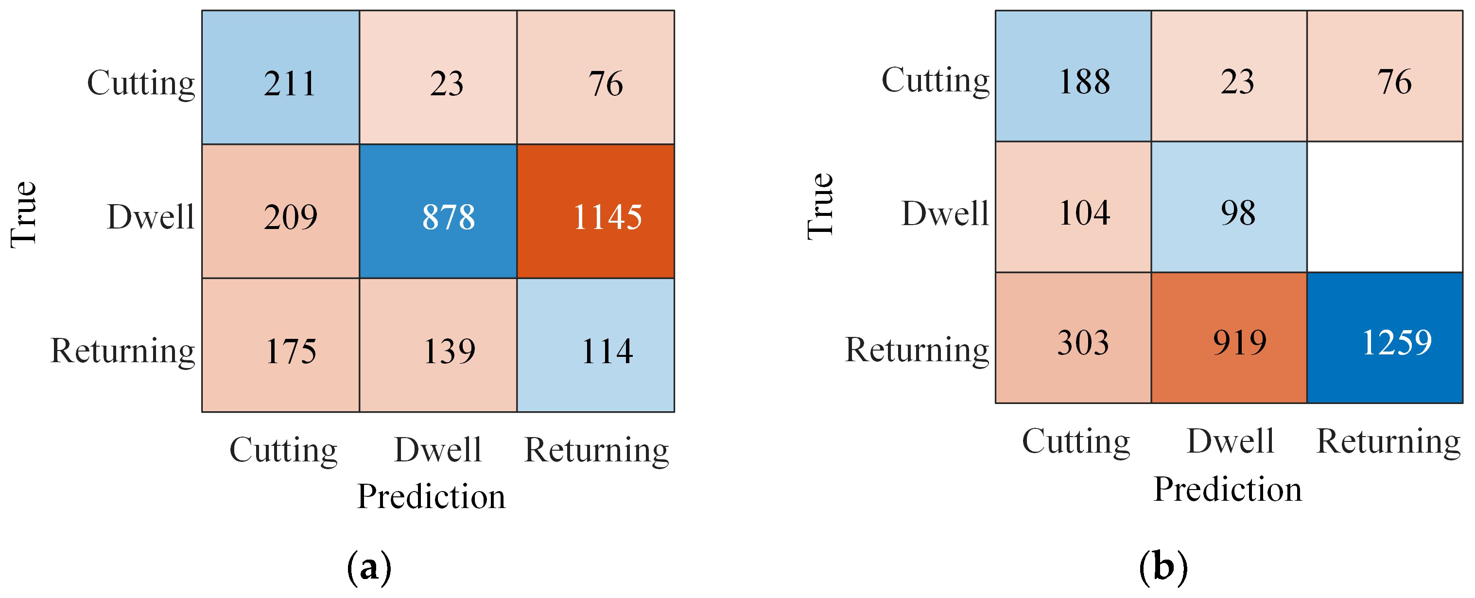
5.1. Accuracy Analysis for State Prediction

Figure 10 presents the accuracy analysis of state predictions in the drilling process, comparing two prediction approaches. In Figure 10a, predictions are based solely on probability scores, yielding an accuracy of 40.5%. This result highlights the limitations of using probability scores alone in complex systems such as the drilling process, where noise and uncertainty often obscure true states.
Figure 10b shows a slight improvement in prediction accuracy to 52.02% by combining probability scores with FSM logic. However, this improvement may mask underlying issues. While the FSM logic aims to structure the predictions by defining state transitions more clearly, the model still struggles in some cases, particularly with misclassifying states for the next state. Although the model still faces challenges in accurately classifying certain states, this result highlights the promise of combining probabilistic methods with logical frameworks. With further refinement, particularly through incorporating AI-driven techniques and leveraging a machine design framework, there is significant potential for achieving even greater accuracy. By better understanding the physical constraints and dynamics of the system, future models can build on this foundation to improve prediction reliability and robustness, paving the way for more precise state estimations in the drilling process.
Although the current performance of the probability score and FSM approach is limited, the results demonstrate significant potential for improvement. The integration of FSM logic with probability scores has shown promise in better structuring state transitions, though misclassifications persist. The reported accuracy of approximately 52%, even after incorporating FSM constraints, reflects the early-stage nature of the approach. However, with the AI-ready design of the machine, the collection of acoustic signals is now feasible, opening the door to more comprehensive data collection. As more data are gathered, the model’s ability to refine its predictions will improve, allowing AI-driven techniques to further optimize the state prediction process. It is important to note that while the system shows promise, the performance is still under development, and the current results should not be overstated. This approach lays the groundwork for a more robust and accurate system, where continuous data feedback will drive performance enhancement, bringing predictions closer to real-world accuracy.

5.2. Open Sound Library

An open sound library for drilling processes provides a valuable resource for researchers and engineers studying machining dynamics, acoustic monitoring, and process optimization. By collecting, processing, and sharing acoustic data from various drilling experiments, such a library enables the broader research community to analyze, benchmark, and innovate without the need to recreate experimental setups. The sound library would include recordings of drilling acoustic emissions captured during experiments on different materials, including acrylic, PTFE, and hardwood. Each dataset would be annotated with key parameters, including material properties (density, thickness, and brittleness), drilling conditions (spindle speed, and feed rate), and notable events (tool engagement, breakthrough, and Returning). By standardizing these parameters, researchers can compare sound patterns across diverse setups and identify trends and correlations. Details on accessing the sound library can be found in the Data Availability section.
Figure 11 presents the specimen used in the experiments to capture the drilling sound library. This library includes raw and processed data, such as spectrograms, frequency-domain analyses, and time-domain waveforms. These signals would highlight dominant frequencies, amplitude variations, and acoustic patterns linked to key drilling events. Annotated spectrograms could mark spindle engagement or material breakthroughs, aiding predictive maintenance and automated state detection.
Datasets with controlled variations in spindle power, or feed rate would allow researchers to analyze how these factors affect acoustic emissions. For example, they could study how feed rates influence frequency bands or how tool wear alters sound patterns over time.
An open-access library would enable researchers to apply machine learning for deeper insights. Supervised models could classify drilling states and detect anomalies, while unsupervised algorithms could identify hidden patterns. This resource would also serve as a benchmark for testing and validating new algorithms.
Additionally, the library would foster collaboration in acoustic monitoring, digital twins, and process optimization. Researchers from academia and industry could contribute datasets, increasing diversity and applicability across various materials and conditions.

5.3. Potential for Other Canned Cycle

Despite this study focusing solely on through-hole drilling, the machine’s state monitoring using acoustics shows strong potential for applicability to other types of canned drilling cycles. For interrupted cuts—where the tool periodically retracts and re-engages with the material—the system has the capacity to detect each engagement event. This behavior is analogous to the Pre-drilling and Cutting states observed in this study, where the tool approaches the workpiece, establishes contact, and initiates material removal. The acoustic response during these transitions reflects variations in the drill bit’s dynamics, driven by changes in cutting force and material resistance. In interrupted cuts, the frequent retraction and re-engagement introduce additional dynamic fluctuations, which are expected to result in more transient acoustic signatures. These variations could offer even richer information for monitoring.
For blind hole drilling, where the drill stops at a certain depth, there is no direct comparison to the results observed in through-hole drilling. However, this study demonstrates that the acoustic signals correlate with drill velocity and material resistance. When the drill pauses at a certain depth, the material resistance typically transitions from thrusting to a state of no thrusting. At this point, the drill begins to clear out any remaining material and refine the hole. As the hole becomes fully cleared, the material resistance should diminish. This dynamic recovery process during the drilling cycle can be observed in the returning state, reflecting changes in the acoustic signature as the drill transitions through different stages of engagement.
This study shows the potential of acoustic monitoring for through-hole drilling and suggests applicability to other canned cycles, such as blind hole drilling and dwell phases. Future work will explore expanding this system to detect events in these additional cycles, enhancing various drilling operations.

6. Conclusions

This study demonstrates how acoustic-based monitoring can assist high-speed CNC drilling by enabling observation of operational states. By correlating acoustic signals with main drilling events, it demonstrates the value of non-invasive, real-time monitoring for understanding machining dynamics. The integration of spectrogram analysis, Fast Fourier Transform, and DBSCAN clustering enables accurate classification of states such as Cutting, Breakthrough, and Returning, enhancing process optimization, tool condition monitoring, and predictive maintenance.
Experimental results emphasize the material-specific nature of acoustic profiles. PTFE exhibits smoother, lower-frequency signals, whereas hardwood produces high-frequency, rougher patterns, illustrating how material properties influence acoustic emissions and machining performance. The findings indicate that, by combining probability scores with FSM logic, time series predictions of the drilling process state can be effectively made, achieving an accuracy of 52.02%. While this result shows promise, further improvements can be expected with more data and refinement of the prediction model. The development of an open sound library supports collaboration and innovation in intelligent manufacturing and acoustic monitoring.
This research establishes in-situ acoustic monitoring as a transformative tool for modern manufacturing. By integrating big data concepts and AI-driven algorithms, the system lays the foundation for future advancements in CNC drilling. Future research could expand data libraries, apply advanced machine learning techniques, and integrate digital twin technologies for real-time simulation and enhanced process control, paving the way for smarter, more efficient manufacturing systems.

Author Contributions

Conceptualization, P.P. and R.C.; methodology, P.P., K.C. and W.C.; software, P.P., P.C. and K.C.; validation, P.P. and R.C.; formal analysis, P.P., K.C., C.R. and R.C.; investigation, P.P., K.C., P.C. and W.C.; resources, R.C. and W.C.; data curation, P.P. and P.C.; writing—original draft preparation, P.P. and R.C.; writing—review and editing, C.R. and R.C.; visualization, P.P., W.C. and R.C.; supervision, C.R. and R.C.; project administration, R.C.; funding acquisition, R.C. All authors have read and agreed to the published version of the manuscript.

Funding

This research project is supported by Thailand Science Research and Innovation Fund (IND_FF_68_209_2100_031), Chulalongkorn University.

Data Availability Statement

The data supporting the findings of this study are publicly accessible at https://github.com/PimolkanPian/Drilling-sound-processing (accessed on 28 January 2025) and https://www.kaggle.com/datasets/pimolkanpian/drilling-sound-processing (accessed on 17 April 2025).

Conflicts of Interest

The authors declare no conflicts of interest.

References

  1. Chaiprabha, K.; Chanchareon, R. Innovative Smart Drilling with Critical Event Detection and Material Classification. J. Manuf. Mater. Process. 2023, 7, 155. [Google Scholar] [CrossRef]
  2. Szwajka, K.; Zielińska-Szwajka, J.; Trzepieciński, T. Experimental Analysis of Smart Drilling for the Furniture Industry in the Era of Industry 4.0. Materials 2024, 17, 2033. [Google Scholar] [CrossRef] [PubMed]
  3. Yue, X.; Yue, Z.; Yan, Y.; Li, Y. Experimental study on predicting rock properties using sound level characteristics along the borehole during drilling. Bull. Eng. Geol. Environ. 2023, 82, 310. [Google Scholar] [CrossRef]
  4. Govekar, E.; Gradišek, J.; Grabec, I. Analysis of acoustic emission signals and monitoring of machining processes. Ultrasonics 2000, 38, 598–603. [Google Scholar] [CrossRef]
  5. Hase, A. In Situ Measurement of the Machining State in Small-Diameter Drilling by Acoustic Emission Sensing. Coatings 2024, 14, 193. [Google Scholar] [CrossRef]
  6. Uhlmann, E.; Holznagel, T. Acoustic emission-based process monitoring in the milling of carbon fibre-reinforced plastics. CIRP J. Manuf. Sci. Technol. 2022, 37, 464–476. [Google Scholar] [CrossRef]
  7. Chacón, J.L.F.; de Barrena, T.F.; García, A.; de Buruaga, M.S.; Badiola, X.; Vicente, J. A novel machine learning-based methodology for tool wear prediction using acoustic emission signals. Sensors 2021, 21, 5984. [Google Scholar] [CrossRef] [PubMed]
  8. Mohammad, A.; Belayneh, M. Field Telemetry Drilling Dataset Modeling with Multivariable Regression, Group Method Data Handling, Artificial Neural Network, and the Proposed Group-Method-Data-Handling-Featured Artificial Neural Network. Appl. Sci. 2024, 14, 2273. [Google Scholar] [CrossRef]
  9. Kasiviswanathan, S.; Gnanasekaran, S.; Thangamuthu, M.; Rakkiyannan, J. Machine-Learning- and Internet-of-Things-Driven Techniques for Monitoring Tool Wear in Machining Process: A Comprehensive Review. J. Sens. Actuator Netw. 2024, 13, 53. [Google Scholar] [CrossRef]
  10. Hase, A.; Wada, M.; Koga, T.; Mishina, H. The relationship between acoustic emission signals and cutting phenomena in turning process. Int. J. Adv. Manuf. Technol. 2014, 70, 947–955. [Google Scholar] [CrossRef]
  11. Elhadi, A.; Slamani, M.; Amroune, S.; Arslane, M.; Chatelain, J.F.; Jawaid, M.; Bidi, T. Precision drilling optimization in jute/palm fiber reinforced hybrid composites. Meas. J. Int. Meas. Confed. 2024, 236, 115066. [Google Scholar] [CrossRef]
  12. Velayudham, A.; Krishnamurthy, R.; Soundarapandian, T. Acoustic emission based drill condition monitoring during drilling of glass/phenolic polymeric composite using wavelet packet transform. Mater. Sci. Eng. A 2005, 412, 141–145. [Google Scholar] [CrossRef]
  13. Marinescu, I.; Axinte, D.A. A critical analysis of effectiveness of acoustic emission signals to detect tool and workpiece malfunctions in milling operations. Int. J. Mach. Tools Manuf. 2008, 48, 1148–1160. [Google Scholar] [CrossRef]
  14. Iatsenko, D.; McClintock, P.V.E.; Stefanovska, A. Extraction of instantaneous frequencies from ridges in time–frequency representations of signals. Signal Process. 2016, 125, 290–303. [Google Scholar] [CrossRef]
  15. Bai, X.; Qiao, G.; Liu, Z.; Zhu, W. Investigation of transient machining in the cortical bone drilling process by conventional and axial vibration-assisted drilling methods. Proc. Inst. Mech. Eng. Part H J. Eng. Med. 2023, 237, 489–501. [Google Scholar] [CrossRef]
  16. Retiti Diop Emane, C.; Song, S.; Lee, H.; Choi, D.; Lim, J.; Bok, K.; Yoo, J. Anomaly Detection Based on GCNs and DBSCAN in a Large-Scale Graph. Electronics 2024, 13, 2625. [Google Scholar] [CrossRef]
  17. Kanyama, M.N.; Bhunu Shava, F.; Gamundani, A.M.; Hartmann, A. Machine learning applications for anomaly detection in Smart Water Metering Networks: A systematic review. Phys. Chem. Earth 2024, 134, 103558. [Google Scholar] [CrossRef]
  18. Cheng, Y.; Li, Y.; Li, G.; Liu, X.; Xia, J.; Liu, C.; Hao, X. Tool breakage monitoring driven by the real-time predicted spindle cutting torque using spindle servo signals. Robot. Comput. Integr. Manuf. 2025, 92, 102888. [Google Scholar] [CrossRef]
  19. Hagag, A.M.; Yousef, L.S.; Abdelmaguid, T.F. Multi-Criteria Decision-Making for Machine Selection in Manufacturing and Construction: Recent Trends. Mathematics 2023, 11, 631. [Google Scholar] [CrossRef]
  20. Bustillo, A.; Urbikain, G.; Perez, J.M.; Pereira, O.M.; Lopez de Lacalle, L.N. Smart optimization of a friction-drilling process based on boosting ensembles. J. Manuf. Syst. 2018, 48, 108–121. [Google Scholar] [CrossRef]
  21. Everson, C.E.; Hoessein Cheraghi, S. The application of acoustic emission for precision drilling process monitoring. Int. J. Mach. Tools Manuf. 1999, 39, 371–387. [Google Scholar] [CrossRef]
  22. Xu, N.; Li, M.; Fang, S.; Huang, C.; Chen, C.; Zhao, Y.; Mao, F.; Deng, T.; Wang, Y. Research on the detection of the hole in wood based on acoustic emission frequency sweeping. Constr. Build. Mater. 2023, 400, 132761. [Google Scholar] [CrossRef]
  23. Du, S.; Huang, C.; Ma, X.; Fan, H. A Review of Data-Driven Intelligent Monitoring for Geological Drilling Processes. Processes 2024, 12, 2478. [Google Scholar] [CrossRef]
  24. Yadav, A.; Garg, R.K.; Sachdeva, A. Artificial intelligence applications for information management in sustainable supply chain management: A systematic review and future research agenda. Int. J. Inf. Manag. Data Insights 2024, 4, 100292. [Google Scholar] [CrossRef]
  25. Pacheco, D.A.D.J.; Iwaszczenko, B. Unravelling human-centric tensions towards Industry 5.0: Literature review, resolution strategies and research agenda. Digit. Bus. 2024, 4, 100090. [Google Scholar] [CrossRef]
  26. Reeber, T.; Henninger, J.; Weingarz, N.; Simon, P.M.; Berndt, M.; Glatt, M.; Kirsch, B.; Eisseler, R.; Aurich, J.C.; Möhring, H.C. Tool condition monitoring in drilling processes using anomaly detection approaches based on control internal data. Procedia CIRP 2024, 121, 216–221. [Google Scholar] [CrossRef]
  27. Rahman, M.A.; Saleh, T.; Jahan, M.P.; McGarry, C.; Chaudhari, A.; Huang, R.; Tauhiduzzaman, M.; Ahmed, A.; Mahmud, A.A.; Bhuiyan, M.S.; et al. Review of Intelligence for Additive and Subtractive Manufacturing: Current Status and Future Prospects. Micromachines 2023, 14, 508. [Google Scholar] [CrossRef]
  28. Peña, B.; Aramendi, G.; Rivero, A.; De Lacalle, L.N.L. Monitoring of drilling for burr detection using spindle torque. Int. J. Mach. Tools Manuf. 2005, 45, 1614–1621. [Google Scholar] [CrossRef]
  29. López De Lacalle, L.N.; Pérez-Bilbatua, J.; Sánchez, J.A.; Llorente, J.I.; Gutiérrez, A.; Albóniga, J. Using high pressure coolant in the drilling and turning of low machinability alloys. Int. J. Adv. Manuf. Technol. 2000, 16, 85–91. [Google Scholar] [CrossRef]
  30. Bunian, S.; Al-Ebrahim, M.A.; Nour, A.A. Role and Applications of Artificial Intelligence and Machine Learning in Manufacturing Engineering: A Review. Eng. Sci. 2024, 29, 1088. [Google Scholar] [CrossRef]
  31. Presciuttini, A.; Cantini, A.; Costa, F.; Portioli-Staudacher, A. Machine learning applications on IoT data in manufacturing operations and their interpretability implications: A systematic literature review. J. Manuf. Syst. 2024, 74, 477–486. [Google Scholar] [CrossRef]
  32. Basavarajappa, S.; Chandramohan, G.; Davim, J.P. Some studies on drilling of hybrid metal matrix composites based on Taguchi techniques. J. Mater. Process. Technol. 2008, 196, 332–338. [Google Scholar] [CrossRef]
  33. Bakkal, M.; Shih, A.J.; McSpadden, S.B.; Liu, C.T.; Scattergood, R.O. Light emission, chip morphology, and burr formation in drilling the bulk metallic glass. Int. J. Mach. Tools Manuf. 2005, 45, 741–752. [Google Scholar] [CrossRef]
  34. López de Lacalle, L.N.; Lamikiz, A.; Muñoa, J.; Salgado, M.A.; Sánchez, J.A. Improving the high-speed finishing of forming tools for advanced high-strength steels (AHSS). Int. J. Adv. Manuf. Technol. 2006, 29, 49–63. [Google Scholar] [CrossRef]
  35. Drumheller, D.S.; Knudsen, S.D. The propagation of sound waves in drill strings. J. Acoust. Soc. Am. 1995, 97, 2116–2125. [Google Scholar] [CrossRef]
  36. Wang, Q.; Bi, C.; Zhang, J.; Wang, H.; Guan, Z. Experimental Study on Downhole Acoustic Wave Propagation Characteristics in Curved Drill String. Processes 2023, 11, 1525. [Google Scholar] [CrossRef]
  37. Daraba, D.; Pop, F.; Daraba, C. Digital Twin Used in Real-Time Monitoring of Operations Performed on CNC Technological Equipment. Appl. Sci. 2024, 14, 10088. [Google Scholar] [CrossRef]
  38. Birkelid, A.H.; Eikevåg, S.W.; Elverum, C.W.; Steinert, M. High-performance polymer 3D printing—Open-source liquid cooled scalable printer design. HardwareX 2022, 11, e00265. [Google Scholar] [CrossRef] [PubMed]
  39. Avni, Y.; Danial-Saad, A.; Sheidin, J.; Kuflik, T. Enhancing museum accessibility for blind and low vision visitors through interactive multimodal tangible interfaces. Int. J. Hum. Comput. Stud. 2025, 198, 103469. [Google Scholar] [CrossRef]
  40. Tůma, P. Advances in the design and application of contactless conductivity detectors for separation, flow-through, microfluidic and sensing techniques: A review. Anal. Chim. Acta 2025, 1337, 343325. [Google Scholar] [CrossRef]
  41. Dávila, J.L.; Manzini, B.M.; Lopes da Fonsêca, J.H.; Mancilla Corzo, I.J.; Neto, P.I.; Aparecida de Lima Montalvão, S.; Annichino-Bizzacchi, J.M.; Akira d’Ávila, M.; Lopes da Silva, J.V. A parameterized g-code compiler for scaffolds 3D bioprinting. Bioprinting 2022, 27, e00222. [Google Scholar] [CrossRef]
  42. Kumar, S.; Sayyad, S.; Bongale, A. Fault Classification of 3D-Printing Operations Using Different Types of Machine and Deep Learning Techniques. AI 2024, 5, 1759–1778. [Google Scholar] [CrossRef]
  43. Hu, Z.; Wang, J.; Wang, G.; Wen, S.; Li, Z. Extraction of time-frequency ridge line based on automatic peak search and curve fitting. Eng. Res. Express 2024, 6, 025502. [Google Scholar] [CrossRef]
  44. Ryalat, M.; Franco, E.; Elmoaqet, H.; Almtireen, N.; Al-Refai, G. The Integration of Advanced Mechatronic Systems into Industry 4.0 for Smart Manufacturing. Sustainability 2024, 16, 8504. [Google Scholar] [CrossRef]
  45. Moreira, M.V.; Landon, Y.; Araujo, A.C. A Timed Automaton Model with Timing Intervals and Outputs for Fault Diagnosis of the Drilling Process on a CNC Machine. J. Control Autom. Electr. Syst. 2023, 34, 1207–1219. [Google Scholar] [CrossRef]
  46. Sun, J.; Xi, R.; Jiang, Z.; Xia, G.; Dai, Y.; Zhang, J. Auditory perception based milling posture detection and depth control enhancement for orthopedic robots. Measurement 2025, 239, 115448. [Google Scholar] [CrossRef]
  47. Damilos, S.; Saliakas, S.; Karasavvas, D.; Koumoulos, E.P. An Overview of Tools and Challenges for Safety Evaluation and Exposure Assessment in Industry 4.0. Appl. Sci. 2024, 14, 4207. [Google Scholar] [CrossRef]
  48. Wang, T.; Li, J.; Kong, Z.; Liu, X.; Snoussi, H.; Lv, H. Digital twin improved via visual question answering for vision-language interactive mode in human–machine collaboration. J. Manuf. Syst. 2021, 58, 261–269. [Google Scholar] [CrossRef]
  49. Ntemi, M.; Paraschos, S.; Karakostas, A.; Gialampoukidis, I.; Vrochidis, S.; Kompatsiaris, I. Infrastructure monitoring and quality diagnosis in CNC machining: A review. CIRP J. Manuf. Sci. Technol. 2022, 38, 631–649. [Google Scholar] [CrossRef]
  50. Stradovnik, S.; Hace, A. Workpiece Placement Optimization for Robot Machining Based on the Evaluation of Feasible Kinematic Directional Capabilities. Appl. Sci. 2024, 14, 1531. [Google Scholar] [CrossRef]
Figure 1. The experimental CNC drilling machine with vision and sound monitoring.
Machines 13 00372 g001
Figure 2. Implementation of a digital twin for the CNC drilling machine.
Machines 13 00372 g002
Figure 3. Mechanics of the drilling mechanism.
Machines 13 00372 g003
Figure 4. The design of AI-ready CNC drilling machine. (a) Architecture with Klipper firmware. (b) AI-enhanced data processing.
Machines 13 00372 g004
Figure 5. Finite state machine of drilling process automation.
Machines 13 00372 g005
Figure 6. The processed sound captured during cutting: Acrylic. The L, D and H represent L—Low feed rate at 50 mm/min, D—Dwell, and H—High feed rate at 150 mm/min. The 60, 80, and 100 represent input power in watts.
Machines 13 00372 g006
Figure 7. The processed sound captured during cutting: (a) PTFE; (b) Hardwood. The L, D and H represent L—Low feed rate at 50 mm/min, D—Dwell, and H—High feed rate at 150 mm/min. The 60, 80, and 100 represent input power in watts.
Machines 13 00372 g007aMachines 13 00372 g007b
Figure 8. Acoustic signal analysis framework. (a) Main ridge, first derivative of the ridge, second derivative of the ridge, and clusters of dominant frequency components. (b) Extracted signal showing the estimated probability of drilling process states (green: Cutting, red: Dwell, and blue: Returning) along with the spindle power state.
Machines 13 00372 g008
Figure 9. Processed acoustic signal in high-speed CNC drilling of (a) PTFE and (b) Hardwood.
Machines 13 00372 g009
Figure 10. Accuracy analysis of state predictions in the drilling process. (a) Predictions based solely on probability scores, achieving an accuracy of 40.5%. (b) Enhanced predictions by integrating probability scores with finite state machine logic, leading to an improved accuracy of 52.02%.
Machines 13 00372 g010
Figure 11. Library of drill materials: PTFE, Acrylic, Hardwood.
Machines 13 00372 g011
Table 1. Mathematical variables.
VariableDescription
F , F 0 , F 1 Total, constant and amplitude of cyclic force
C Cyclic function representing the periodic behavior of the force
f Frequency of the cyclic force
A n , ϕ n Amplitude and phase of the nth sinusoidal component in Fourier expansion
u t Displacement of the surface that produces mechanical wave as a function of time
m Mass of the system
c Damping coefficient
k Stiffness of the system
P ,   P 0 Pressure at position x and time t and maximum pressure at the source of a sound
α Attenuation coefficient
x Distance the sound wave has traveled
τ m Motor’s torque of drilling machine.
K i Motor’s torque constant.
R Resistance of the motor.
V Input voltage to the motor.
K v Motor’s speed constant.
ω Angular velocity of the spindle.
J Moment of inertia of the spindle system.
τ r Resistive torque in drilling process.
Disclaimer/Publisher’s Note: The statements, opinions and data contained in all publications are solely those of the individual author(s) and contributor(s) and not of MDPI and/or the editor(s). MDPI and/or the editor(s) disclaim responsibility for any injury to people or property resulting from any ideas, methods, instructions or products referred to in the content.

