1. Introduction
The development of fusion energy technology could lead to the deployment of high-output, carbon-free tokamak reactors in the future. ITER, the world’s largest experimental tokamak, is currently under construction, and the European successor, EU DEMO, is now being designed with the aim of demonstrating the technical and economic readiness of fusion energy while providing net electricity to the grid [
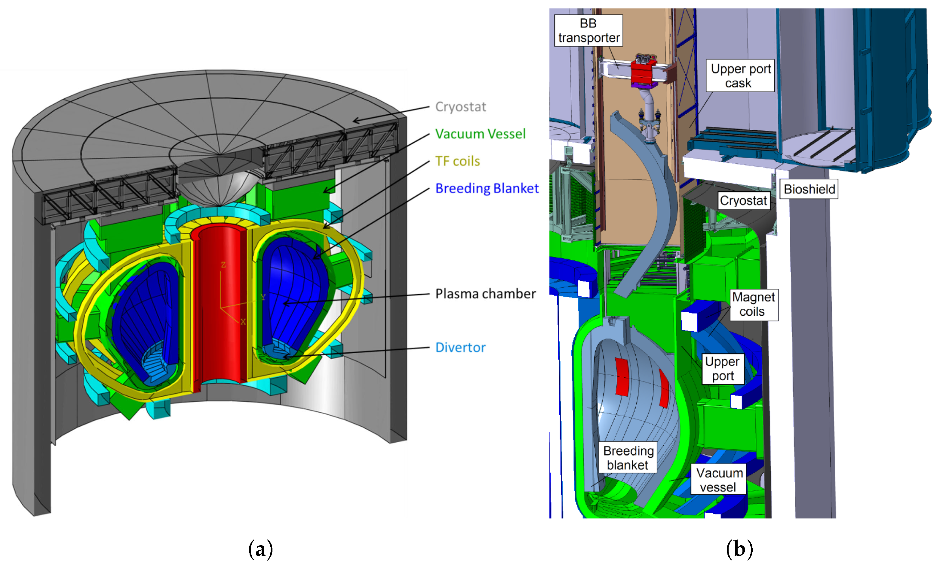
1]. In addition to being larger and experiencing greater heat and mechanical loads than ITER, the DEMO tokamak (
Figure 1a) will also integrate a self-sufficient tritium lifecycle based on breeding blankets (BBs) lining the inner vacuum vessel [
2]. The BBs will be the largest and heaviest in-vessel components and will require occasioreplacement due to material degradation from neutron irradiation. It is a requirement that this remote maintenance task be carried out safely while minimizing the down-time of the plant [
3].
Unlike ITER, European DEMO will use a vertical maintenance architecture for the BBs, which has also been considered for earlier tokamaks including INTOR [
4]. This entails the maintenance of three 180
outboard and two 125
BB segments within each of the 16 tokamak sectors using a mobile cask that docks to a sector’s upper port and contains the necessary remote handling (RH) equipment to remove or replace a BB segment. This concept is illustrated in
Figure 1b, depicting a robotic RH tool vertically transporting a BB segment within the confines of the vacuum vessel, upper port, and cask. This tool is the BB vertical transporter (BBVT), which was previously introduced in [
5,
6]. The idealized handling task requires the 3-D translation of each BB segment, plus rotation about the vertical and toroidal axes, in order to avoid collisions with the walls and neighboring BB segments during removal. Ignoring the trolley tilting joint, which is the subject of this work, the BBVT can be analyzed as a redundant serial robotic manipulator with six joints enabling this 5-degree-of-freedom task. A detailed kinematic model of the BBVT is derived in [
7].
Figure 1.
The DEMO tokamak and its vertical breeding blanket maintenance concept. (
a) DEMO tokamak components; (
b) BBVT handles a BB segment via the upper port. Reproduced from [
6].
Figure 1.
The DEMO tokamak and its vertical breeding blanket maintenance concept. (
a) DEMO tokamak components; (
b) BBVT handles a BB segment via the upper port. Reproduced from [
6].
Attachment and support structures for the BB segments, seen in
Figure 2a, were introduced in [
8] and further developed in [
9,
10]. These include radial, vertical, and toroidal support structures which react against the different loading conditions of the BB segments during the operation of the tokamak. When the tokamak is powered down, as is the case during maintenance, each BB segment is vertically supported only at the bottom and can be lifted by a countersunk interface in the portion of the top surface exposed in the port [
11]. A short vertical translation and toroidal tilt are required to free each BB segment from its lower supports.
Besides the vertical load, the BBVT is also subject to large moments [
12]. This is due to the fact that the countersunk interface by which each BB segment is grasped is horizontally offset from the center of mass to be accessible by the BBVT inside the upper port. However, rather than being automatically reacted by the BBVT when initially loading a BB segment for lifting, these moments are primarily reacted by the radial and toroidal BB segment supports. This is a problem, as these loads could damage the supports as the contact surface areas shrink during disengagement. This is of particular concern for the toroidal shear keys. Thus, these horizontal moment components must be actively counteracted by the BBVT to avoid loading the supports during disengagement, as illustrated in
Figure 2b.
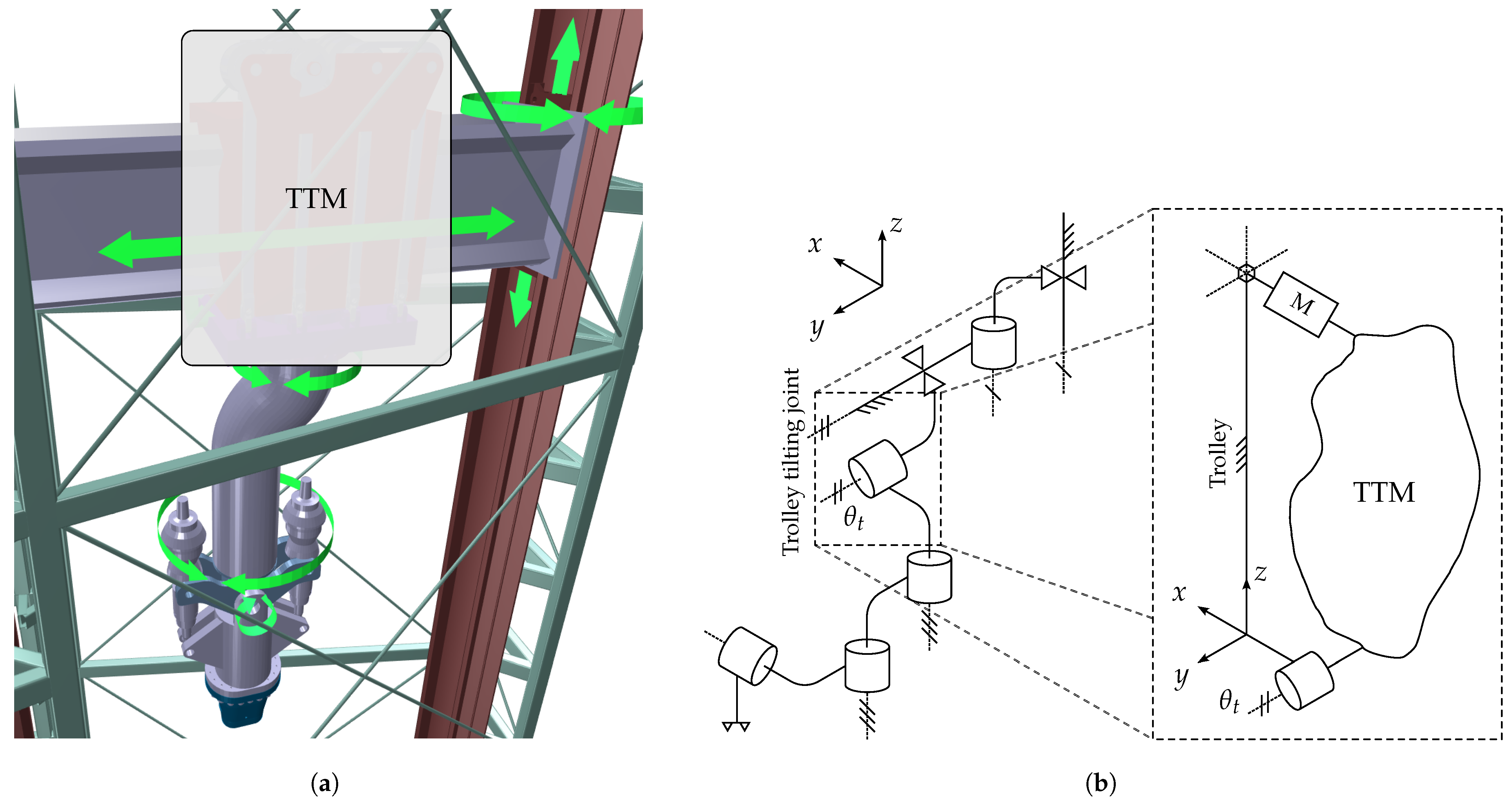
The need to counteract the BB segment support reactions during initial lifting motivates the incorporation of a radial tilting joint in addition to the toroidal tilting joint required for the kinematic BB segment removal task. Due to space constraints, the toroidal tilting joint is adjacent to the gripper and is referred to as the gripper tilting joint, while the radial tilting joint is incorporated in the central sliding trolley link and is referred to as the trolley tilting joint. Kinematically, this joint is also useful for adjusting the radial tilt by approximately 0.5° to 1.5° in order to ensure proper alignment to the interface during engagement in the non-ideal task. A major consideration for the design of the trolley tilting mechanism (TTM) is to minimize the trolley’s horizontal footprint, since this affects the workspace of the BBVT. Minimization of the required actuator size is also important in this regard, thus a mechanism with favorable mechanical advantage is sought.
Figure 3 shows the location of the TTM as part of the BBVT both visually and schematically.
A five-bar RSRRR mechanism is proposed and designed in this work to address this unique set of challenges for the TTM. A kinematic model of the linkage is established and applied to analyze and optimize the design, and numerical simulations and experiments are performed to validate the design and the kinematic model.
Spatial linkages have been well studied. In 1983, ref. [
13] derived generic but relatively complex (in terms of the number of coordinates and constraint equations) kinematic models of all single-loop spatial five-bar mechanisms, including the RSRRR, as combinations of different three-bar mechanisms with a crank. In 1996, ref. [
14] analyzed the mobility of spatial four- and five-bar mechanisms with revolute and spherical joints. The bulk of recent research on applications of five-bar mechanisms appears to focus on spherical mechanisms, such as a spherical remote center of motion [
15], a translational parallel manipulator based on two five-bar mechanisms [
16], and a spherical adaptive gripper mechanism [
17]. The mechanism proposed in this work is also closely related to the spatial four-bar RSSR linkage, the kinematics of which have been thoroughly analyzed [
18,
19] and which has found many applications, such as the recently designed steering mechanism of a gravity-powered vehicle [
20]. Linkages with compliant members have also been studied extensively and applied widely, such as the use of a method for the analysis of flexible RSSR mechanisms using the pseudo-rigid-body model [
21] and a mechanism for improved safety in robotic surgery [
22].
The current work is divided into six sections. In
Section 2, Mechanism Design, the design requirements and considerations for the TTM are detailed, and the current design is presented. In
Section 3, Kinematics, the kinematic constraint equations for the TTM are derived and an analytical solution for the forward kinematics is presented, along with the configuration-dependent transmission ratio. In
Section 4, Mechanical Design Optimization, the kinematic model is used as a basis to optimize two of the bar lengths with respect to range of motion and maximum static loads on the mechanism output and input during BB segment maintenance. In
Section 5, Verification and Preliminary Down-Scaled Experiment, the kinematic model is verified by comparisons with a numerical simulation in ADAM and further validated by initial experiments on a down-scaled TTM prototype. Finally, in
Section 6, Discussion and Conclusions, the results and contributions are discussed, and limitations and future work presented.
2. Mechanism Design
The main requirements for the TTM are to “preload” the 180 outboard and 125 inboard lateral BB segments with a radial moment to counter the formation of reactions within the support structures during lifting and to provide the ability to adjust the radial tilt of the gripper by a small angle (about 0.5° to 1.5°) in order to align it during engagement with the BB segment’s countersunk interface. Note that the latter requirement does not apply in the ideal case, where there should be no misalignments, gaps, or deformations which would require a radial gripper tilt. Thus, the idealized range of motion requirement is zero, while the realistic requirement depends on the rough estimation of these unknowns. This discourages the use of kinematic synthesis techniques based on the required output motion.
As indicated in
Figure 3b, the TTM is placed as the fourth joint of the BBVT, between the links referred to as the trolley and the trunk. The reason for this is that the space adjacent to the gripper itself is taken by the gripper’s tilting joint, and the trolley is the next-closest link with available space. However, even here, the horizontal space is limited as the trolley (essentially a box) must fit within the constricted upper port while the BBVT is engaged with each of the 5 BB segments. As the trolley slides on a large radial rail, the radial faces are nearly inaccessible. Also, the lower vertical face is largely occupied by the trunk connection. Thus, the only practical location for the TTM actuator(s) is on the upper face, and the output radial motion must be applied to a tilting plate sitting between the trolley and trunk. The problem, then, is to connect the actuator(s) and tilting plate while affecting the toroidal and radial dimensions of the trolley assembly minimally. This combination of requirements and restrictions is difficult to solve compactly and reliably using only conventional transmission elements such as gearboxes, belts, chains, or screws.
Thus, a compact five-bar mechanism providing good mechanical advantage was designed, as shown in
Figure 4a. It is a spatial linkage with structure RSRRR, where “R” denotes a revolute joint and “S” denotes a spherical joint, with the Grübler criterion equal to 1. The four mobile bars have been marked with their lengths
a,
b,
c, and
d. The first (
a) is the eccentricity of a cam connected to the input shaft. This is connected via a radial bearing with spherical housing to the rod
b. At its lower end, the rod attaches to a short connector
c, which connects the rod and the tilting plate
d using pins at right angles. The plate connects back to the trolley at the tilting hinge, which constitutes the TTM output.
The design of the mechanism is inspired by a planar four-bar mechanism, where a mechanical advantage is gained by the relative sizing of the bars connected to the input and output joints, while the connecting bars in between serve primarily to transfer the load. The mechanism wraps around the vertical and toroidal faces of the trolley, which is required in order to not interfere with the radial rail. However, a planar four-bar mechanism cannot carry this out while having good leverage and avoiding collision with the trolley. Instead, the input axis located above the trolley is made to be toroidal and perpendicular to the output axis. Then, a short extra bar (c) is added to connect the radial output and toroidal input. The main connecting bar (b) must then be able to tilt both toroidally and radially due to the interconnected motion of the input and output bars, necessitating the use of a spherical connection between a and b, in this case chosen as a radial bearing with spherical housing. This configuration also gives space radially along the top surface of the trolley to place multiple tilting mechanisms in parallel to reduce the load on the input actuator(s).
3. Kinematics
The optimization and control of the TTM require an accurate kinematic model, which will be derived in this section. Although kinematic models of five-bar RSRRR mechanisms exist, since the TTM is a special case, a model using only five relative rotation coordinates and 4 equations (compared with 15 equations in [
13]) is derived based on the schematic diagram in
Figure 4b. The coordinates are
,
,
,
, and
, where
is the joint variable associated with the input of the mechanism and
is associated with the output. The input shaft and output shaft angles are each defined as being zero when their respective bars (
a and
d) are horizontal. The following assumptions are made: the rotation axes of the joints
and
are pairwise perpendicular, and the rotation axes of the joints
are all parallel.
With reference to the schematic (
Figure 4b), the following four independent equations constrain the kinematics:
where
are the constant coordinates of the mechanism output point relative to the input point. For simplicity, and to ensure that
when
, these will be assumed to take on the values
,
, and
when the equations are applied throughout this work, although it is not strictly necessary. For example, in the case of replacing the input cam with one of different size
without also adjusting
and
d, this would not hold.
3.1. Forward Kinematic Solution
The forward kinematic solution presented here follows from the assumption that only is known, and it describes a procedure for calculating the remaining coordinates in the model. However, solutions are not substituted to be in terms of only , since this quickly leads to complex nested expressions.
Treating the input angle
as given, Equation (
1) gives
directly:
By squaring and summing Equations (2) and (3) and utilizing Equation (4),
can be found in terms of
and
:
Physically valid and non-extraneous solutions are obtained by only taking the positive solutions for Equations (6) and (9).
Using Equation (4),
can be eliminated from Equations (2) and (3). The system of equations can then be solved for
in terms of known and derived angles (
,
, and
) by taking advantage of the fact that a system of equations of the form
has the following solution:
To find
, the solutions for
and
can be plugged into Equation (4). Alternatively, the same procedure used to find
can be applied, but using Equation (4) to eliminate
from Equations (2) and (3). Also, rather than relying on Equation (
13), alternative forms of the solutions for
and/or
can be found using the tangent of the half-angle substitution method.
3.2. Transmission Ratio and Mechanical Advantage
The constraint Equations (
1)–(3) can be differentiated with respect to time to give the following velocity constraints:
where
is the vector of time derivatives of the coordinates, and
is the Jacobian matrix of the constraint equations:
The system of four equations in Equation (
15) can be solved to find the ratio of input and output speeds or transmission ratio
:
By the conservation of energy and neglecting inertia and friction forces, the input power must equal the output power, leading to the assertion of the mechanical advantage provided by the mechanism:
where
and
are the torques at the input shaft and output hinge, respectively.
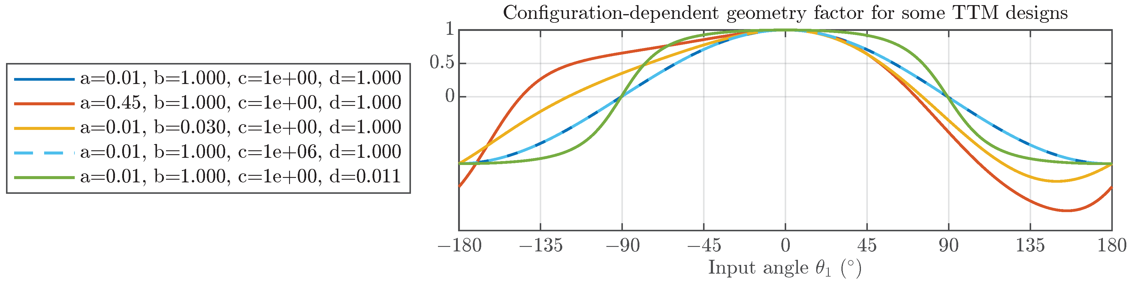
The factor in parentheses in Equation (
18) depends on the configuration of the mechanism, as well as the chosen bar lengths. This is illustrated by
Figure 5, where factor
g is plotted as a function of the input angle for several TTM designs. As can be seen,
g is sensitive to
a,
b, or
d but does not depend strongly on
c. When
, the mechanism is in a kinematic singularity where the output velocity goes to 0 regardless of the input velocity.
3.3. Inverse Kinematics
Although an analytical solution of the kinematic equations for
exists when
is known, as described in
Section 3.1 above, the inverse is not true. Instead, the mechanism’s configuration can be found numerically using the Newton–Raphson method with the constraint Jacobian Equation (
16), i.e., iteratively solving for
with an equation of the following form:
where
is the vector of constraint Equations (
1)–(4) evaluated at
.
4. Mechanical Design Optimization
An initial sizing of the TTM based only on the space available and the geometry of the BBVT trolley gives
,
,
, and
. However, it is possible to optimize this using the kinematic model derived in
Section 3. Two important properties of interest are the input load, which depends on the transmission ratio, and the output range of motion.
In the home position, the transmission ratio Equation (
17) reduces to the simple ratio of the lengths of the output and input bars:
We will refer Equation (
20) as the base transmission ratio, as the true transmission ratio almost always increases in magnitude when the mechanism is not in home position due to the geometry factor generally obeying
for designs where
and
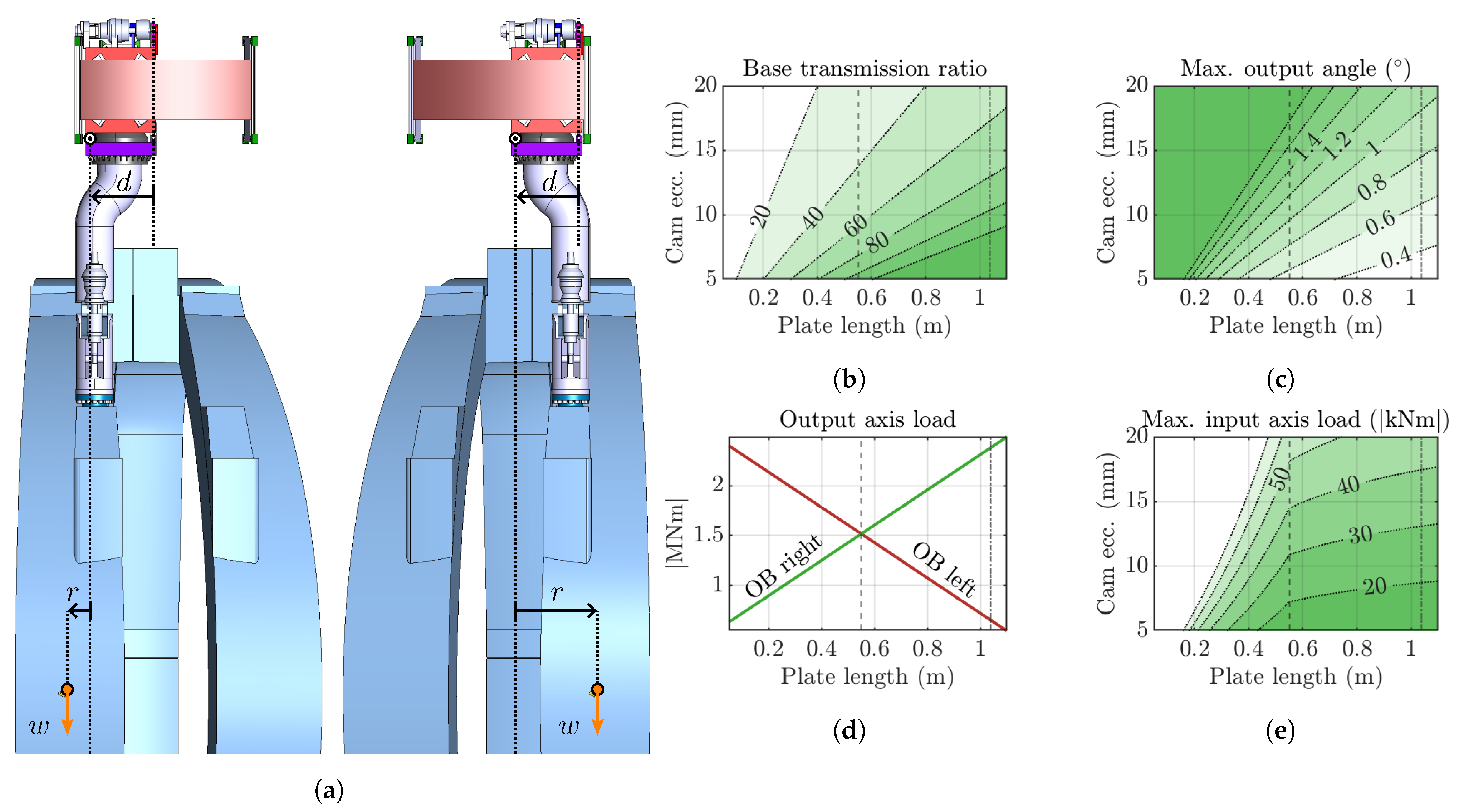
. In order to minimize the sizes of the required actuators and gearboxes, a base transmission ratio of about 50 to 100 is desired.
Figure 6b plots expected values of
for relevant ranges of
a and
d based on Equation (
20), showing that smaller
a and larger
d values are desirable.
Another important property of the mechanism is the output range of motion. Since an exact expression for
and
is difficult to obtain, a simplification is used, namely that the rotating cam (
a) connects directly to the trolley tilting plate (
d). This is valid when
and
since the tilt angles
and
then remain small and contribute negligibly to the change in the height of the far end of the tilting plate. In that case, the maximum output angle corresponds to the input angle
, and using Equation (3),
Note that the simplification also leads to symmetrical extrema,
, which is not true of the exact values.
Figure 6c shows how the estimated
varies for different bar lengths; specifically, smaller
d and larger
a values lead to an increased output range.
It should be noted that both the base transmission ratio and the approximate output range of motion depend exclusively on a and d. Thus, choosing appropriate lengths for the input and output bars is a major design consideration.
Another crucial value to consider is the load on the actuator gearbox connected to the TTM input. This depends not only on the transmission ratio and therefore the internal TTM geometry but also on the external problem geometry relating to the use case of lifting the BB segments. This is illustrated in
Figure 6a, which shows the difference in the problem setup between the outboard’s (OB) left and right BB segments. These are the two which produce the greatest radial moments at the gripper interface due to their offset centers of mass. The radial moment load on the TTM output axis is different in each case due to the variable horizontal arm
r, which depends on the chosen tilting plate length
d.
Figure 6d shows that a value of
gives equal loads on the output axis in the two cases, thus minimizing the overall largest load. By taking the larger of the two loads for a given value of
d and dividing by the corresponding
, the maximum load on the TTM input is found (
Figure 6e). This is not only useful for choosing
a and
d but also enables the optimal sizing of the input actuator(s) and gearbox(es).
The optimization problem can be stated as the minimization of the maximum input actuator load while respecting the required range of motion
to overcome misalignments, gaps, and deflections during operation (as well as the maximum input actuator load rating
):
where
w is the BB segment weight, and
in
Figure 6a. The value of
u depends on whether the left or right outboard segment is considered (and on the chosen configuration of the redundant BB transporter mechanism during initial lifting), leading to the two actuator load expressions.
The analysis supports the idea of using a centered hinge, thus fixing d, one of the two main design variables. The centered hinge has the advantage of resulting in fully symmetric loading cases () assuming symmetric BBVT configurations. The optimization is then a simple matter of minimizing a (which minimizes the actuator load) subject to the constraints.
6. Discussion and Conclusions
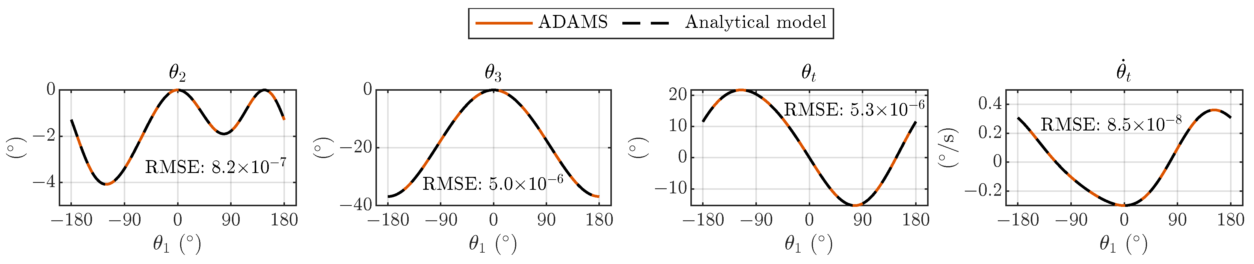
The predictions by the analytical model of the TTM joint positions and output shaft speed show great agreement with the numerical simulation in Adams, verifying the basic accuracy of the model. Although the experimental results show some small deviations compared with the predicted output shaft motions, the agreement is overall still good, and the discrepancies can be explained by geometrical uncertainties and material flexibility inherent in the plastic additive manufacturing of the down-scaled prototype.
A five-bar tilting mechanism was proposed and designed for the trolley tilting joint of the BBVT, and a detailed kinematic model was derived, verified by numerical simulations, and validated by experiment. Thus, the kinematic relationships between the mechanism’s input and output position, speed, and torque have been shown. In addition, the relationships of the base transmission ratio, output range of motion, output axis load, and input axis load to the cam eccentricity a and tilting plate length d have been detailed, allowing for the intelligent dimensioning of these parameters together with the joint gearbox(es) and actuator(s). The model has thus been applied in designing and optimizing the mechanism with respect to the very large static loads which it will experience during operation within the future DEMO power plant, supporting the feasibility of the TTM as a solution for safely lifting the BB segments.
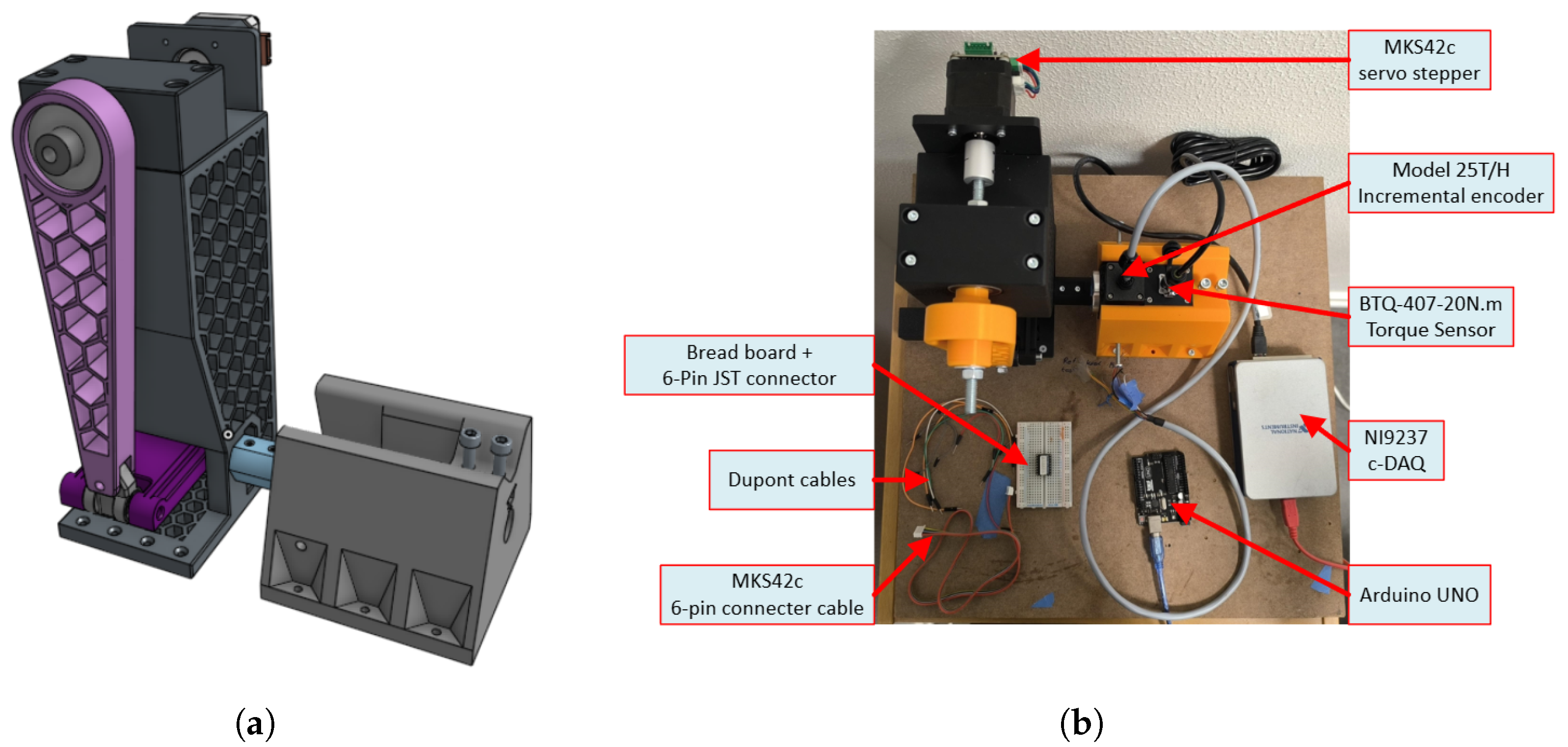
Due to the 3D printing process, the preliminary down-scaled TTM lacks the manufacturing precision and material stiffness required for a highly accurate validation of the kinematic model, especially under load. This also prevents carrying out experiments to validate the mechanical advantage predicted by the model. Thus, the construction of a high-precision down-scaled prototype using sturdier materials is considered essential future work in order to validate the force transmission.
Since the TTM is only foreseen to be used at low speeds, a multibody dynamics model of the mechanism is not considered necessary for now. However, the derived kinematic model can be used as a basis for future modelling, potentially including dynamic effects, as well as control solutions. Due to the high loads, a study of the compliance of the mechanism links and the development of a flexible model is considered for the future. More detailed design explorations guided by the model can also be carried out.


 ,
, 
