Abstract
Material removal processes such as milling, drilling, and turning often generate harmful vibrations that can negatively impact both machine performance and operator safety. Addressing these vibrations at their source or reducing them to safe levels is, therefore, a critical challenge. This study proposes a practical solution by introducing thin-fin-type vibration-absorbing devices fabricated using 3D printing technology. These devices are designed specifically to mitigate vibration propagation during milling operations. To evaluate their effectiveness, a multi-sensor system comprising sound level meters, a vibrometer, and a vision–acoustic camera was employed to measure sound levels. The results show that the use of fabricated devices can reduce noise levels significantly, from 93 dB (comparable to power tools or a lawn mower) to 74 dB (similar to normal conversation or a busy office). This substantial reduction demonstrates the potential of the proposed devices to enhance workplace safety and acoustic comfort on the shop floor.
1. Introduction
Noise generated during manufacturing processes is an unavoidable element to which workers are easily exposed. Continuous exposure to such noise has been reported to cause not only hearing loss but also an increase in stress hormone levels, as well as a higher risk of sleep disturbances and chronic health conditions [1]. Making custom noise attenuators is time-consuming and expensive, so using rapid manufacturing methods like 3D printing can help meet the urgent need to protect users’ health. Sound is primarily generated by the physical activities of systems, including facilities, machines, and devices. Consequently, noise is generated in numerous forms, such as high sound pressure levels (referred to as loud sounds), soft but continuous sounds, ringing sounds, crackling sounds, and tearing sounds [2]. Among various noise sources, manufacturing processes are among the primary contributors to harmful industrial noise. Operations such as forging, grinding, and machining generate significant sound pressure through impact, friction, and cutting actions [3]. It is known that workers exposed to noise for long periods of time tend to talk at loud volumes due to hearing damage. Because workers who control and monitor noisy processes are directly exposed to this noise, they suffer hearing loss. Researchers have studied how noise affects neural networks and how the nervous system responds to its harmful effects [4,5]. The findings suggest that noise control should be considered essential for user safety. Methods have been devised to prevent harmful noise early on: controlling tolerance, better lubricating machines, constructing machines with softer materials, and installing a protective barrier for the auditory organ (earplugs). However, managing tolerance to make a machine operate more smoothly entails higher production and maintenance costs. Lubricants can be used, but managing the residues mixed with lubricants in machining processes involves complex structures and expensive post-processing. Transforming the materials of machines can be contrasted with ensuring the life and reliability of machines. Covering the ear’s vibrating membrane is one of the simplest and most cost-effective methods. However, this covering can lower work efficiency because it interferes with communication in complex operating processes or user scenes that require communication [6,7]. Recently, noise-canceling technology has enabled people to hear sounds selectively. However, isolating ears from the environment has the disadvantage of exposing users to danger [8]. Therefore, we state that an effective way to eradicate the danger of harmful noise is to control it at the sound generation stage. Additionally, reducing noise sources through simple and low-cost fabrication can help maintain both user safety and process efficiency everywhere.
Based on this research, we suggest a practical and optimal process to solve the noise problem and demonstrate noise reduction. We employed a heat sink to explore significant vibration and noise. Research using heat sinks will advantageously contribute to noise management in various fields. The demand for cooling and managing the heat generated from advanced mobility, high-performance electronic devices, and industrial machines is increasing. This is because high-performance devices have high-density integrated circuits and generate heat [9,10]. Heat sinks are essential heat dissipation solutions for ensuring the stable operation and extended life of high-performance devices. The typical methods for manufacturing heat sinks include forging, molding, and cutting machining [11]. Cutting-based machining was suitable for this study. It is a well-known method that cuts a workpiece using the rotational motion of a sharp cutting tool. It is the most widely used method worldwide due to its low-cost operation, firm quality, and customizable access. As shown in conceptual Figure 1, a milling machine, which is a cutting device, has a motor that generates rotational force. The vibration of the motor in the milling machine is transmitted to the metallic workpiece, and when the rotating tool encounters the heat sink, additional vibration is induced in it. Through the synthesis of the noises produced, we reproduce high-frequency and loud noises. The semi-rigid thin fins of the heat sink undergo repeated bending motions simultaneously. The harmful noise pressure activated by the vibration of multiple fins is added together, amplified, and transmitted to the air medium. According to theories in the literature, direct and indirect vibration noise is generated in the gear contact area by the forces generated during machining, and noise is also generated during material displacement and chip removal processes during machining [12].
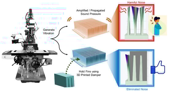
Figure 1.
A concept of facile noise reduction in subtractive machining. The fins’ vibration during heat sink processing generates harmful noise. A reducer created using 3D printing reduces the vibration of the fins and isolates noise propagation.
Thankfully, 3D printing, a prototyping method, has advanced and allows for quick and low-cost forming. Accordingly, an acoustic reducer capable of controlling noise has been fabricated utilizing facile 3D printing to diminish the noise generated during heat sink machining, which proves our idea [13] (Supplementary Video S1). In addition, we verified the advantages of the idea via a sound level meter, a vibrometer, computational simulation, and acoustic cameras to visually and quantitatively reveal the enormous noise that is amplified from the thin fins and then reduced. As a result, we succeeded in effectively reducing the harmful noise generated during the manufacturing process using an easily printable reducer. The noise reducer we created acts as an energy isolation device that reduces the vibration of the fins and reduces the transmission of noise [14]. The proposed idea is an example of using 3D printing to create a functional tool. It represents a time- and cost-efficient method that can be used not only for laboratory-scale prototyping but also to improve the industrial environment in small factories and developing countries. Furthermore, the presented simple yet highly effective method will contribute to expanding 3D printing technology beyond monolithic formation into vibration, control, environmental, automobile, and medical engineering.
2. Methods
2.1. Materials and Tools
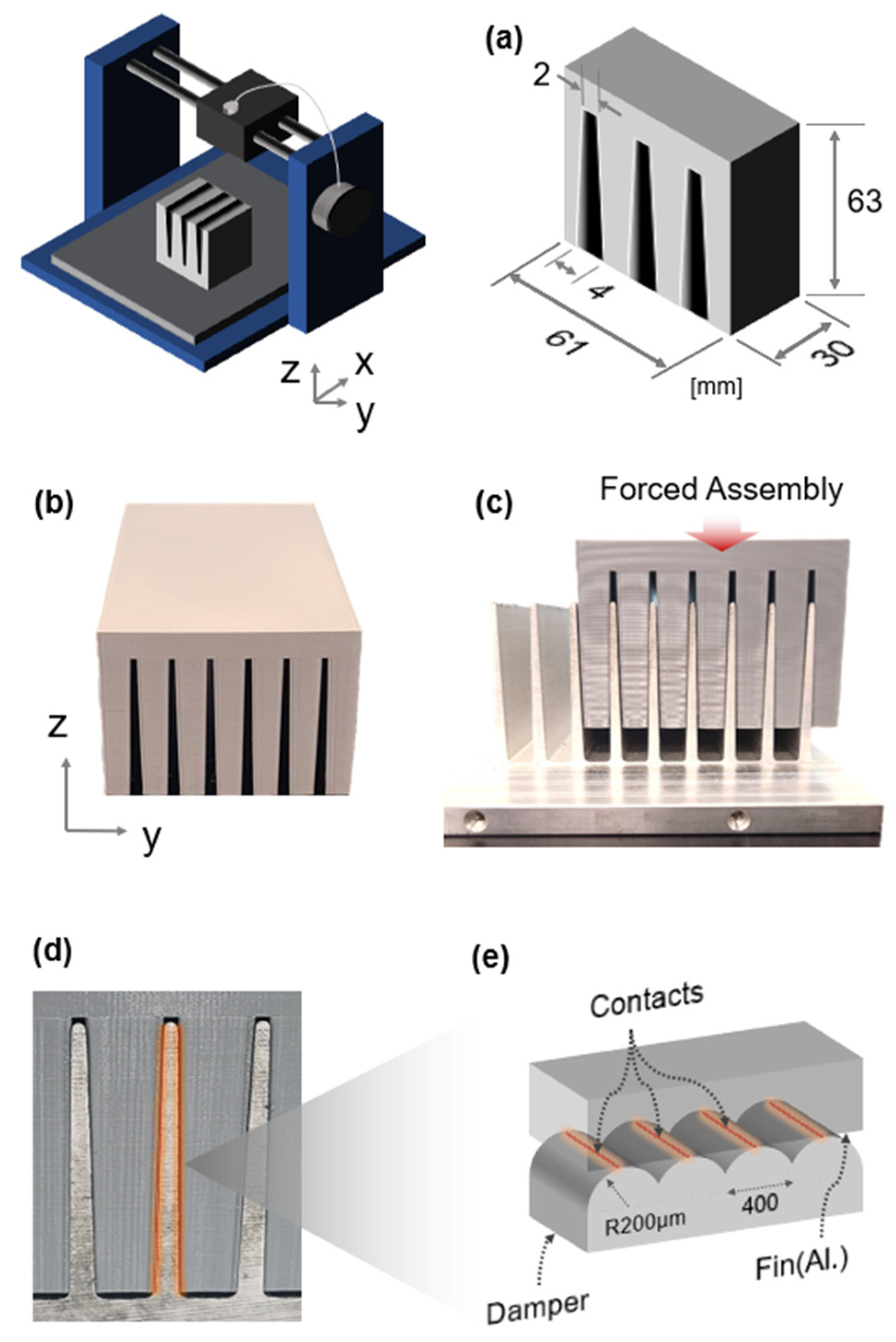
Milling heat sink: The heat sink was made from ADC12 through die casting (187.4 × 10.05 × 96.06 mm). The height of the heat sink’s fin was 53.36 mm. The maximum cross-sectional length of the fins at the bottom was 4.2 mm, while the minimum at the top was 1.6 mm. The thermal conductivity was 131 W/m∙k [15]. The milling machine (HMT-1300; Hwacheon, Gwangju, Republic of Korea, spindle speed, 75~3600 rpm; machine size, 2450 × 2100 × 2300 mm; weight, 2040 kg) was operated to generate vibration noise. When the heat sink was mounted on the milling bed and subjected to the rotational force of the milling cutter, the fins of the heat sink vibrated. The milling cutter used in this experiment was a high-speed drill (HSSCo8, YG-1 Co., Ltd., Incheon, Republic of Korea; diameter, 15 mm).
Fabricating reducer: The reducers were printed using a fused-filament 3D printer (Adventurer 4, FlashForge, Jinhua, China).
Measurement and analysis: The effect of the reducer manufactured by 3D printing was quantified and analyzed using a sound level meter. The sound level meter (RuoShui 824C, Ruoshui instruments, Xi’an, China; measuring range, 30~130 dBA; accuracy, ±1.5 dB; resolution, 0.1 dB; size, 57 × 26 × 149 mm; weight, 173 g) performed spatial analysis around the heat sink. For advanced noise analysis, an acoustic camera (SEESV s200 SM instruments Co., Ltd., Daejeon, Republic of Korea; microphone array, high-resolution camera, 25 FPS (frames per second), BSR (Buzz, Squeak, Rattle) detection, real-time noise localization, octave analysis, and frequency adjustment function) was adopted to visualize the reducer’s effectiveness. After measuring the acoustic pressure using the sound level meter, the noise reduction was verified using a vibrometer (VM-6380Landtek Instruments, China; XYZ 3-axis; frequency range, 10 Hz to 10 kHz; accuracy, 5% of reading + 2 digits). The vibrometer was attached to the fins and measured the speed (mm/s), acceleration (m/s2), and displacement (mm).
2.2. Prototyping
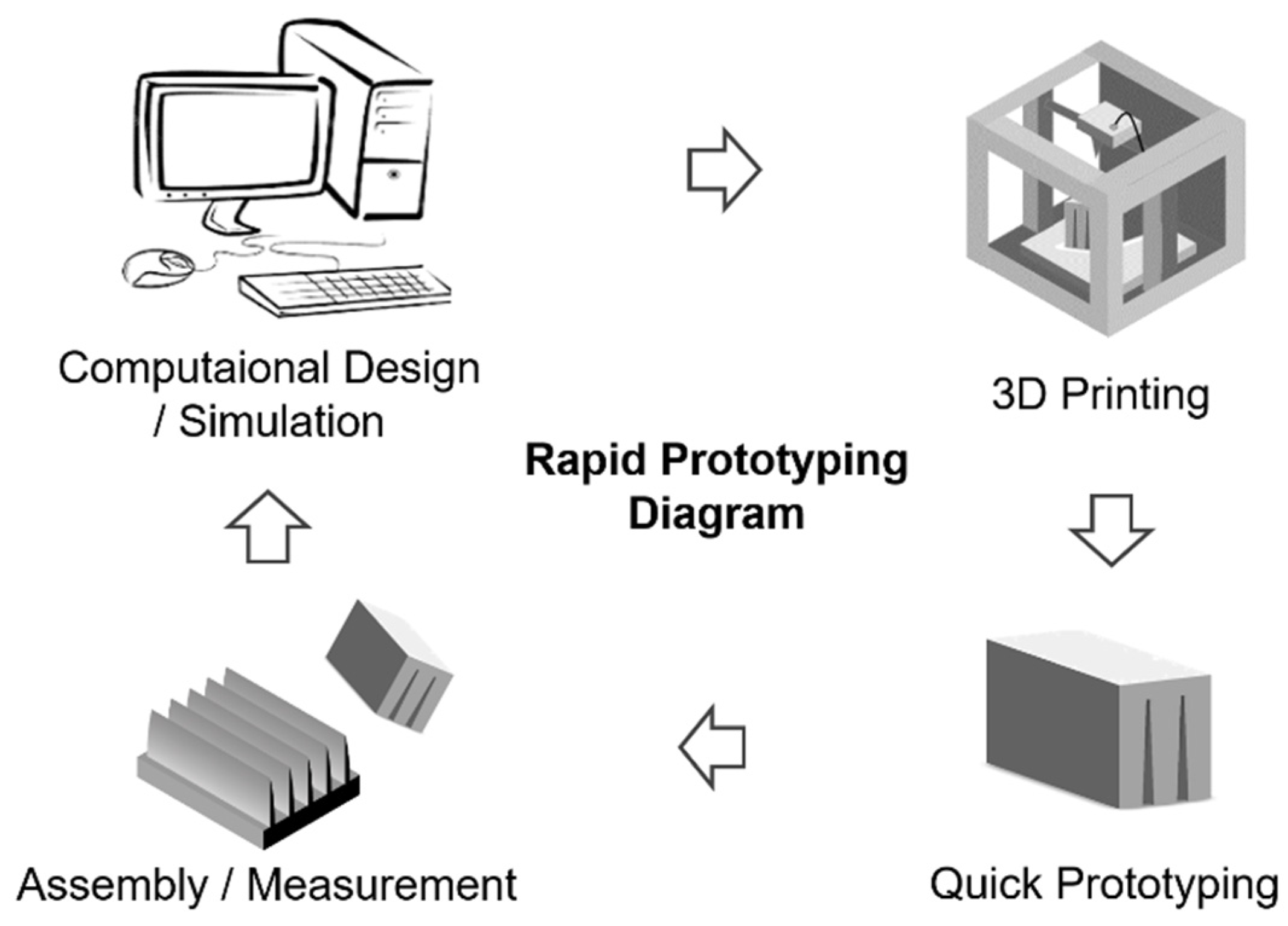
Figure 2 shows the prototyping process for the noise reducers. The design concept of the reducer is to directly suppress high-frequency vibrations generated at the source during the machining of metallic heat sinks, specifically caused by tool contact. To achieve this, a custom 3D-printed acoustic damper was introduced, designed to fit tightly against the fins. The reducer was engineered to allow interference-fit assembly with the sloped geometry of the heat sink fins, ensuring full surface contact. This eliminated air gaps and minimized energy loss at the interface. The internal slits of the reducer were fabricated slightly smaller than the fin dimensions, enabling strong surface friction and tight engagement upon assembly, which promoted vibrational energy dissipation. According to the literature, a lower filling ratio allows the reducer to absorb more energy, while a higher filling ratio can increase the vibration coefficient and increase responsiveness [16]. This structural strategy was validated through COMSOL 6.1 Multiphysics simulation. Details of the simulation are provided in Section 3, which confirms that the vibration can be locally attenuated before being transmitted into the surrounding air medium. As a result, by controlling fin vibrations at their source, the proposed design enables cost-effective and efficient noise mitigation without requiring any modifications to the existing machining process. By enforcing a tight mechanical contact between the sloped fin surface and the reducer slit, frictional interaction is increased, which converts vibrational energy into heat and suppresses acoustic propagation at the source.

Figure 2.
The fabrication process for a printed reducer. Designed using simulation. Rapid prototyping performed using 3D printing. Feedback and design modifications were realized during assembly and measurement.
2.3. Heat Sink
The heat sink has thin fins, which generally have the same width. The fins have slopes designed to be separated from the mold after the die-casting process. Aluminum alloys were employed for high thermal conductivity [15]. Accordingly, the thermal energy provided by the heat source was quickly transferred through the heat sink body and fins. The air passing through the multiple fins removed the thermal energy remaining on the surface of the heat sink. Hence, in the heat sink design, the heat transfer performance varied depending on the dimensions and spacing of the fins. As the spacing of the fins became narrower, the Nusselt number approached 1, enhancing the pure conductivity [17]. Conversely, as the spacing became wider, convection heat transfer came to dominate over pure conduction. Thus, the heat transfers were functionalized depending on the shape of the fins. Because companies and factories employ a variety of designs with different fin materials, spacing, and shapes, which influence heat transfer, the design of the noise reducer for eliminating fin vibration cannot be consistent. Furthermore, fabricating the heat sink entails post-processing, like cutting the die-casted large heat sink into small pieces and drilling screw holes. This is why it is important to be able to easily fabricate custom reducers using simple methods such as 3D printing.
2.4. Subtractive Machining
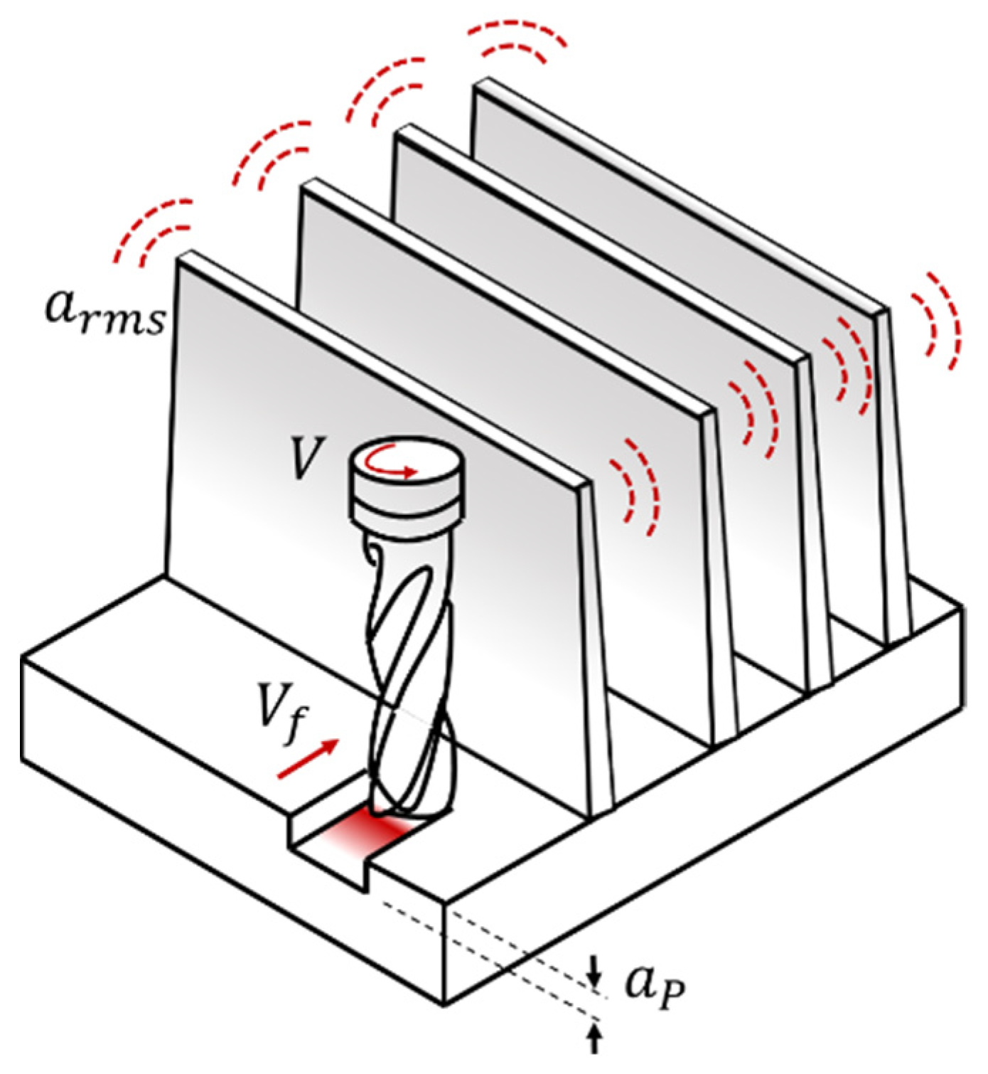
In Figure 3, a schematic representation of the relationship between vibration acceleration and noise levels during subtractive machining processes is provided. During cutting processes such as milling, vibrations are generated due to contact between the tool and workpiece, resonance, tool wear, and chip formation. These vibrations, when transmitted through the workpieces and machines, cause local structural displacement and generate acoustic pressure. The sound energy produced is transmitted through the air. The propagated energy affects the human eardrum and microphone membrane [18,19]. When the vibration exceeds a reference level or includes unwanted vibrations, it is perceived as harmful noise. Specifically, this vibration is amplified when combined with milling parameters such as fast cutter rotation or resonance, exceeding the noise level.
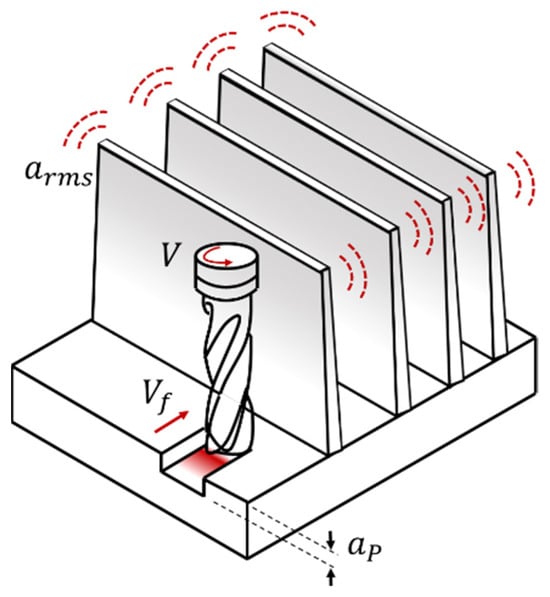
Figure 3.
Schematic diagram of vibratile heat sink subtractive manufacturing. The fins of the heat sinks vibrate during milling.
2.5. Vibration and Noise Theory
In acoustics, the sound level is generally expressed in decibels (dB) using the sound intensity or the amplitude of sound pressure. The sound pressure is calculated as follows [20].
[dB] is the sound pressure level, [Pa] is the average pressure intensity of the measured sound, and [Pa] is the average pressure intensity of the reference. Vibration is a phenomenon of periodic movement in one, two, or three dimensions around an equilibrium position in space. The fins of the heat sink vibrate in three dimensions while being fixed to the heat sink body. The vibration can be interpreted in terms of physical characteristics such as frequency (Hz), amplitude, and acceleration. In production engineering, vibrations during cutting processes like milling or drilling result from contact interactions between the workpiece and the tool. In the cutting machining processes, vibration acceleration and noise can be modeled using regression to estimate the expected sound pressure level [21].
In Equation (2), [dB] is the expected sound pressure level in milling, V [m/min] is the cutting speed, [mm/s] is the feed rate, [mm] is the depth of cut, and [m/s2] is the root-mean-square value of the vibration acceleration. C is a constant term, and x, y, z, and w are regression coefficients. The regression model can predict the effects of vibration acceleration and milling parameters on noise, allowing for the derivation of the optimal conditions for noise reduction. Through the equations, various factors affecting noise generation in the cutting process and their interrelationships can be predicted. The influence of variables such as feed speed and vibration acceleration on sound pressure levels can be identified. In particular, noise level fluctuations due to changes in vibration acceleration (arms) are analyzed.
3. Results and Discussion
3.1. Fabrication
As shown in Figure 4a, the 3D-printed reducer had customized slits at regular intervals so that it could be assembled with the heat sink fins. The reducer manufactured in this study had slits with a slope angle of 2.5°. The slits ensured a stable assembly between the reducer and heat sink, as shown in Figure 4b. The reducer could be designed with various thicknesses and sizes to minimize vibration diffusion. Three-dimensional printing was performed using a 1.75 mm polylactic acid (PLA) filament. The PLA used in 3D printing has an appropriate balance of strength and hardness, so it can actively reduce vibration when attached to dynamic structures [22]. In addition, PLA’s low coefficient of thermal expansion has the advantage of reducing the deformation of the reducer and preventing warping even when heat is generated due to microscopic friction in contacts [23]. In 3D printing, a higher infill density increases structural strength, while a lower density enhances vibrational energy absorption. A thinner layer thickness improves interlayer bonding due to the greater number of deposited layers, whereas thicker layers may weaken adhesion and increase the risk of structural failure. Although higher printing speeds reduce fabrication time, they may compromise the bonding quality and damping performance. To balance damping performance and structural integrity, the infill density was set to 40% during 3D printing. Although lower infill ratios tend to increase energy absorption by providing internal damping, they compromise structural strength. Therefore, 40% was chosen as an optimal trade-off to ensure both mechanical stability and effective vibration attenuation [24]. In Figure 4c, we show the assembly of the printed reducer onto the heat sink using finger force and a rubber hammer. Because both parts had semi-solid properties, it was vital to eliminate the gap between the fin and the reducer. Had the reducer been manufactured with dimensions larger than the design dimensions, the assembly with the heat sink would have been imperfect. Figure 4d provides a close-up view of the forced assembly. The red highlighted area indicates where the fin’s vibration was suppressed. In this experiment, the surfaces had tiny air cavities, as shown in Figure 4e, which depicts the microscale structure. Because 3D printing creates a reducer by stacking filaments, the layers form wrinkles. These wrinkles, when assembled with the flat fin, have line contacts. The air cavities can be modified by the surface polishing of the 3D-printed reducer. The more perfect the contact between these surfaces, the better the vibration suppression and, thus, the more efficient the noise reduction.

Figure 4.
Three-dimensional printed reducer: (a) dimensions; (b) printed reducer in x- and y-axis views; (c) assembly of reducer and heat sink; (d) zoomed-in view of assembled state; (e) microscopic view of contact between reducer and fins.
3.2. Mechanical Analysis
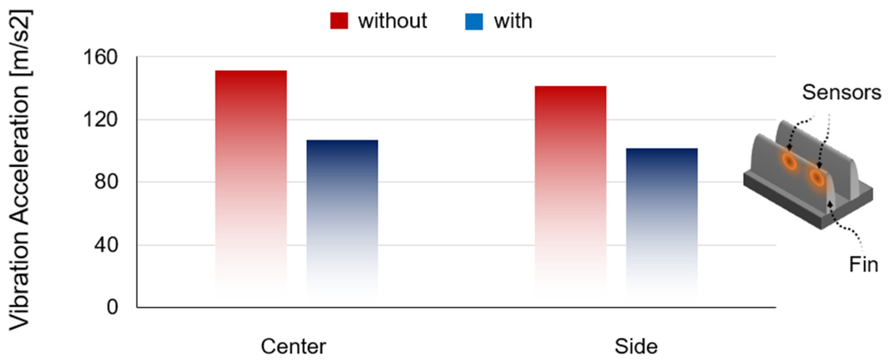
Through the mechanical analysis using this vibration sensing, we proved that the 3D-printed reducer was effective in suppressing vibration. As explained in the theoretical background in Section 2.4, the noise reduction capability of the reducer could be verified by measuring the vibration acceleration applied to the thin fin of the heat sink. In the experiment, the vibration of the heat sink was generated by machining. The milling machine’s spindle rotation speed was set to 1200 rpm. A vibration meter was used to measure the vibration acceleration. As shown in Figure 5, sensors were attached to the center and side of the fins. As a result, the vibration acceleration of the center of the fin was 151.5 m/s2 when machining without the reducer. After assembling the 3D-printed reducer, the vibration acceleration was 107.1 m/s2. It was reduced by 44.4 m/s2 (30%). On the side, the vibration acceleration was 141.7 m/s2, with a reduction of approximately 30% achieved by using the reducer.
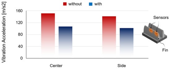
Figure 5.
The reducer’s ability to reduce vibration, determined by measuring the vibration acceleration of the fins.
3.3. Simulation
To test the feasibility of the proposed idea, we utilized an acoustic simulation. The multiphysics modules can predict the quantitative sound pressure level generated by fin vibration during substrative machining. The analysis employed the acoustic wave equation, which describes mechanical vibration noise.
is the density of the medium, an important physical property related to the propagation speed of sound. is the total pressure, defined as the sum of the pressure generated by the sound and the background pressure, allowing the measurement of the magnitude of the pressure produced by the source of vibration. represents an externally generated vibration source, describing the vibrational energy produced during a machine’s milling process. is the equivalent wavenumber. represents the acoustic energy emitted at a specific frequency.
The equation is a pressure component, where is the acoustic pressure and is the background pressure.
is the frequency and is the speed of sound in the medium. For simulation prediction, the heat sink and reducer were modeled. An air medium was applied to the 3D space around the heat sink. Based on the user scene where a milling machine contacted the heat sink’s base, vibration was input. The vibration transmitted to the fins was diffused through the air, and the diffusion phase was analyzed through sound pressure leveling.
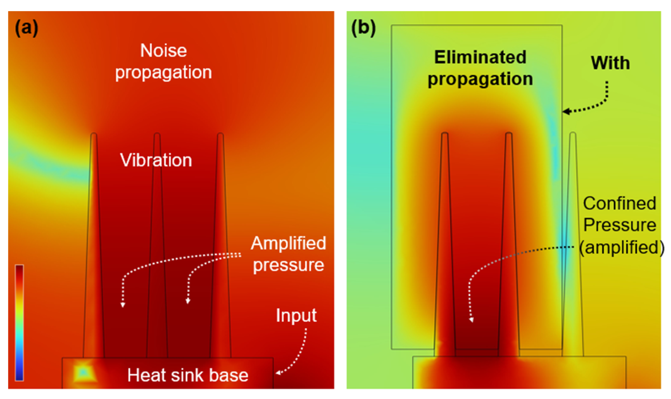
As shown in Figure 6a, first, a heat sink without a reducer was simulated. In particular, vibrations in the air medium between fins interfered with each other, leading to outstanding acoustic amplification. Thus, a tough sound pressure was produced between the fins. Noise generated by the heat sink is evenly transmitted through an air medium with uniform density. If the reducer can confine the sound pressure amplified between the fins, it means that the noise propagating around the processing machine can be eliminated more effectively. As shown in Figure 6b, second, we set the mode with a reducer attached to the heat sink. The simulations compared the effect of the reducer with the same boundary conditions, such as input frequency, materials, and normal temperature. As a result, the generation and propagation of sound pressure were suppressed due to the vibration attenuation and barrier function of the reducer. Note that the intensity of the sound pressure generated on the fin surface was reduced, which means that the reducer diminished the vibration at the noise source. This result supports the idea that the sound pressure can be lowered by reducing the shaking of the fins. In addition, the propagation of the vibration generated between the fins was blocked by the reducer. Despite the reduced vibration, the maximum sound pressure was 121 dB, which is higher than the 105 dB pressure achieved when there was no reducer. This is because the confined vibration was further amplified. This means that the reducer isolates the noise in the local area between the heat sink bases. The simulation supports the claim that the proposed idea can reduce the vibration of the fin and reduce the noise dispersion into the atmosphere.
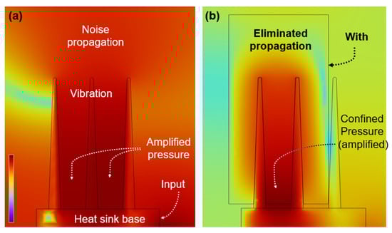
Figure 6.
Sound propagation in simulation: (a) the sound produced by the fins without a reducer was amplified between the fins and transmitted through the air; (b) the reducer eliminated the vibration of the fins and confined the propagation.
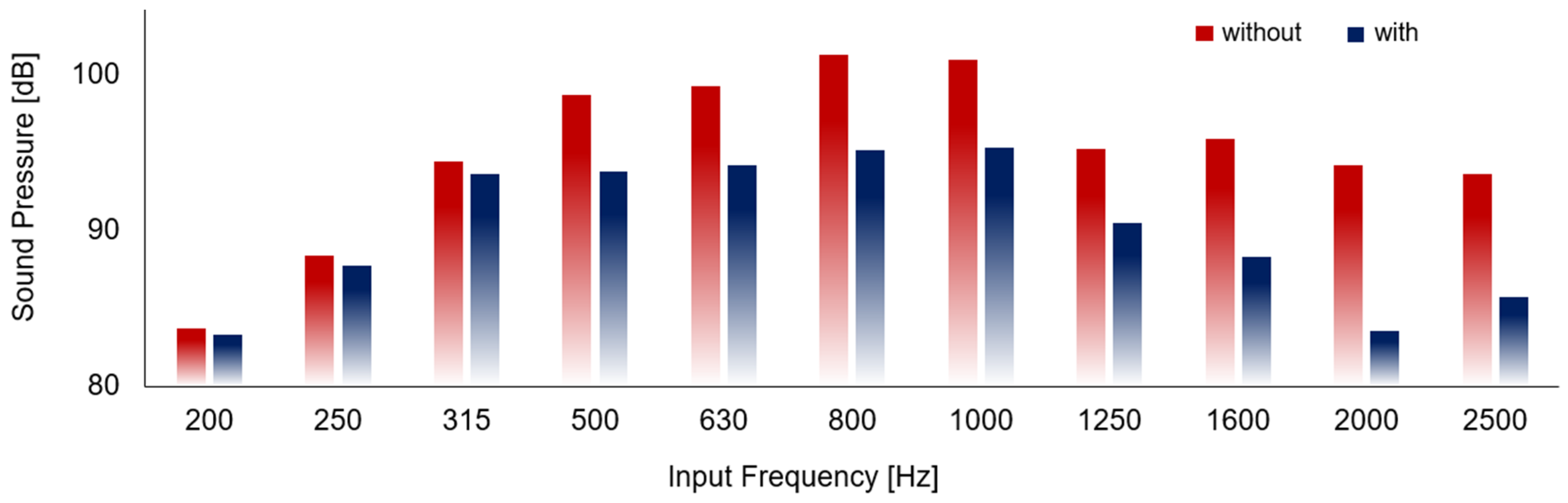
As shown in Figure 7, the effectiveness was further evaluated using a parametric sweep simulation. The frequency range was set as a variable, and results were obtained as its value changed incrementally within the specified range. Because the vibrating sources are very diverse in the actual manufacturing process, we targeted the vibration input in the simulation to the range of 200~2500 [Hz]. As a result, the reducer was effective above 500 Hz, with its performance improving as frequency increased. The initial sound pressure reduction was about 1~3% in the 200 Hz to 315 Hz range. It had an average sound pressure reduction capability of about 5~6% in the 500 Hz to 1250 Hz range. It had an average sound pressure reduction capability of about 7.8% above 1600 Hz. As with general physical phenomena, the sound pressure produced by vibration could be observed to be amplified as the vibration frequency increased. Conversely, the sound pressure decreased by about 4.7 dB in the range of 1250 Hz or higher. The decrease occurred when the input frequency matched the heat sink’s natural frequency, causing resonance. At this point, vibrations exhibited weak damping as the amplitude increased [25]. The reduction phenomenon can also be seen as the sound-absorbing ability of the reducer at a certain frequency. Therefore, when the reducer was assembled on the fin, the effect of the reducer and the sound-absorbing ability of the heat sink was boosted, further lowering the sound pressure level. The prediction through simulation suggested that the reducer was effective in noise reduction.
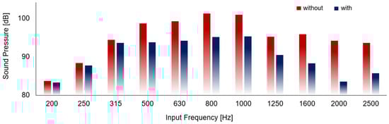
Figure 7.
Sound pressure level according to reducer and various vibration frequencies.
In Figure 8, the appropriateness of materials is analyzed. To evaluate the noise reduction performance by material, reducers made of thermoplastic polyurethane (TPU) and PLA materials were considered and simulated. Additionally, various frequencies ranging from 50 Hz to 10,000 Hz were applied. Overall, the sound levels showed no significant differences, which means that there is freedom in material selection. However, at a high range of 4000 Hz and above, the sound level of the PLA reducer was 1.84% lower than that of the TPU reducer. The rubbery properties of TPU can be considered to have a low ability to suppress fin vibration at high frequencies. Although the difference in noise suppression performance between PLA and TPU was small and could be ignored, in this study, we selected PLA, with its higher performance in some frequency ranges. In the computer simulation, however, the slits of the reducer were in contact with the fins of the heat sink without a gap, so the vibration could be ideally suppressed. Thus, the effect may vary depending on the manufacturing precision for the actual heat sink and reducer.
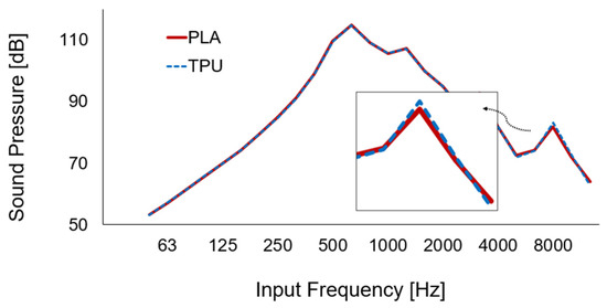
Figure 8.
Sound pressure level depending on the various vibration frequencies with PLA and TPU materials.
3.4. Acoustic Measurement and Analysis
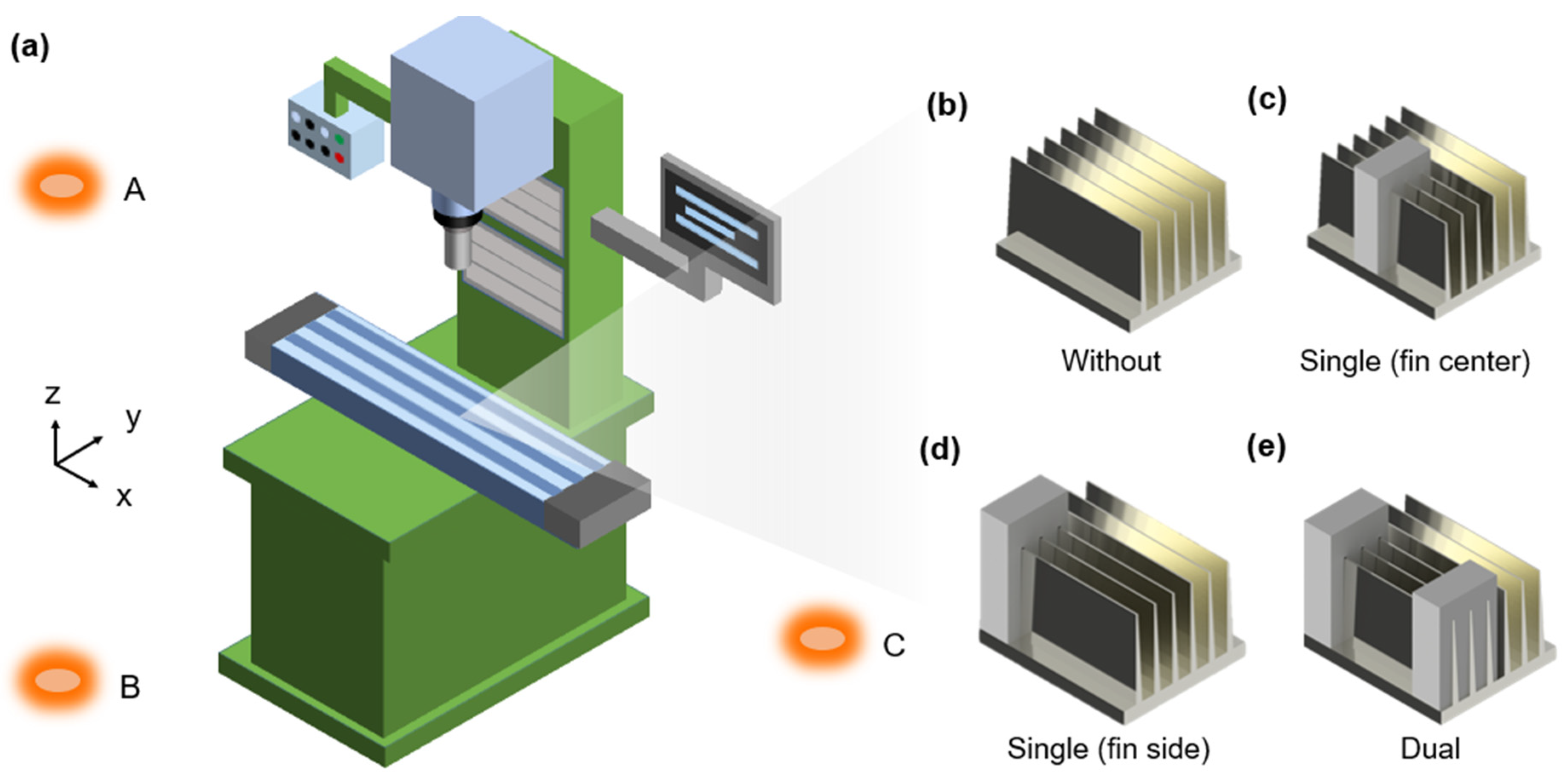
Figure 9 shows the spatial noise analysis. As shown in Figure 9a, three locations on a 2D plane equal to the heat sink machining height were selected to set the sound meter: front (A, a 100 mm distance from the heat sink), left (B), and right (C). Therefore, the noise propagation levels in the x and y directions of the machined heat sink could be measured and analyzed simultaneously. As shown by the sound pressure levels in Table 1, the heat sink without the reducer assembly, as shown in Figure 9b, had sound pressures of 92.8, 92.3, and 91.6 dBA at positions A, B, and C, respectively. The fins provide an average of 92.2 dBA of noise through the air medium. The relatively high sound pressure at A, the front of the machine, is due to noise reflected by the machine body contributing to the amplification. The negative pressures at B and C, measured symmetrically left and right relative to the machine center, were similar to what we predicted.

Figure 9.
Spatial analysis using sound level meters: (a) A to C are sound meters; (b) measurement without reducers; (c) single reducer assembled on the center; (d) single reducer on the side; (e) dual reducer on both sides of fins.

Table 1.
Sound pressure depending on measurement position, reducer assembly, and number of reducers.
As shown in Figure 9c–e, to analyze the effect of the position where the reducer was assembled on the fin, reducers were assembled at various positions, and the noise level at each position was measured. This is because producing large-sized reducers requires expensive large-scale 3D printers, which can impose a financial burden on small and medium-sized companies manufacturing heat sinks. Thus, partially mounting small-sized reducers could enable effective production using smaller, more accessible 3D printers. When a reducer was functionalized at the center of the x-axis length of the fins, the sound pressures were 91.4, 91.6, and 92 dBA at locations A, B, and C, respectively. The average noise level was 91.7 dBA, which was a 0.55% decrease compared to the noise level in the machine without a reducer. In addition, when a reducer was functionalized at the end of the x-axis of the fin, the sound pressures were 91.5, 92.8, and 91.7 dBA at locations A, B, and C, respectively. The average noise level was 92 dBA, a 0.22% decrease compared to the noise level in the machining process without a reducer. Based on the experimental results, single reducers insufficiently reduced the sound pressure. Thus, the effect of the reducer’s length on the fin’s vibration reduction was evaluated. Reducers with x-axis lengths of 30 and 90 mm were prepared by 3D printing. Measurements with a sound level meter indicated that the 30 mm long reducer showed an average level of 92 dBA, and the 90 mm reducer showed a level of 91.7 dBA. Considering the tolerance accuracy of the sound level meter of ±1.5 dB, it reduced noise, but its effect was limited. Therefore, sequential experiments were performed to confirm that using a single reducer could reduce noise. However, this did not appear to be effective enough to eliminate harmful noise for users. The dual reducer’s notable effectiveness will be explained in the next section.
As shown in Figure 9e, significant noise reductions were obtained when two reducers were assembled at both ends of the heat sink fin. The sound pressure at locations A, B, and C decreased by 74.1, 76.7, and 76.1 dBA, respectively. This marked 20.2%, 17%, and 16.9% decreases. The average noise level was 75.6 dBA, an 18.1% decrease compared to the 92.2 dBA observed without reducers. As with the measurement data described in the previous section, the heat sink without reducers resulted in an average of 92 dBA. When the single reducer was used, the sound pressure level remained at 91 to 92 dBA. However, dual reducers reduced the pressure level to 74~76 dBA. These results indicate that when one reducer is assembled, the free area of the fins still vibrates, so noise is generated. Two reducers symmetrically assembled on both sides of the heat sink can reduce the vibration of the fin evenly, making more effective noise reduction possible.
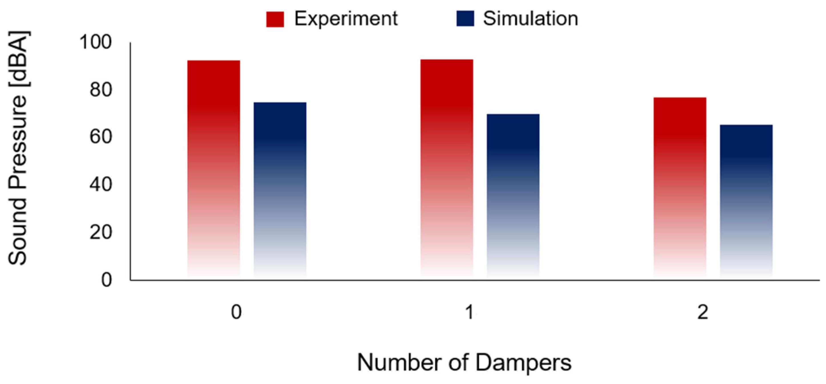
Figure 10 shows the sound level measurement and simulation according to the number of reducers, which facilitated a comparative analysis of the study’s findings. The simulation predictions were different from the experimental results. When the reducer was not assembled, 72 dBA was expected. When one reducer was assembled, 69 dBA was expected, and when two reducers were assembled, 65 dBA was expected. The results were 4.2% and 10% reductions compared to the case without reducers, respectively. The overall trend of sound pressure reduction with the addition of reducers was consistent between the simulation and experimental results, supporting both the concept and findings. However, the simulation exhibited a more idealized linear relationship, whereas the experimental data showed slight variations due to real-world conditions.

Figure 10.
Sound pressure according to the number of reducers determined via measurements and simulations.
These differences can be interpreted as resulting from discrepancies in the conditions between the simulation and experiment. In particular, the simulation was based on idealized assumptions, which likely contributed to the deviation from real-world results. In the ideal simulation scenario, it was assumed that the contact surfaces were perfectly contacted without any gaps, leading to a higher damping performance. However, in reality, as depicted in Figure 4e, the surface of the 3D-printed filament layers includes microscopic roughness that is not reflected in the simulation model. Therefore, if the surface roughness of the printed component were to be incorporated into the simulation or if the damping coefficient were to be calibrated using experimental data, the simulation results could be brought closer to the actual behavior. In addition, the dimensional tolerance of the 3D-printed reducer may reduce the reducer’s influence on the system’s vibration. Note that the vibration reduction was ideal when the heat sink fins and the reducer were assembled without a gap [26]. Based on experiments and simulations, it has been argued that, for effective noise reduction, it is important to place multiple reducers symmetrically rather than simply increasing the length of the reducer. Furthermore, it has been argued that making the contact area fine or manufacturing the shape precisely so that all the joints are tightly engaged can improve performance.
3.5. Verification: Visualizing Noise Reduction
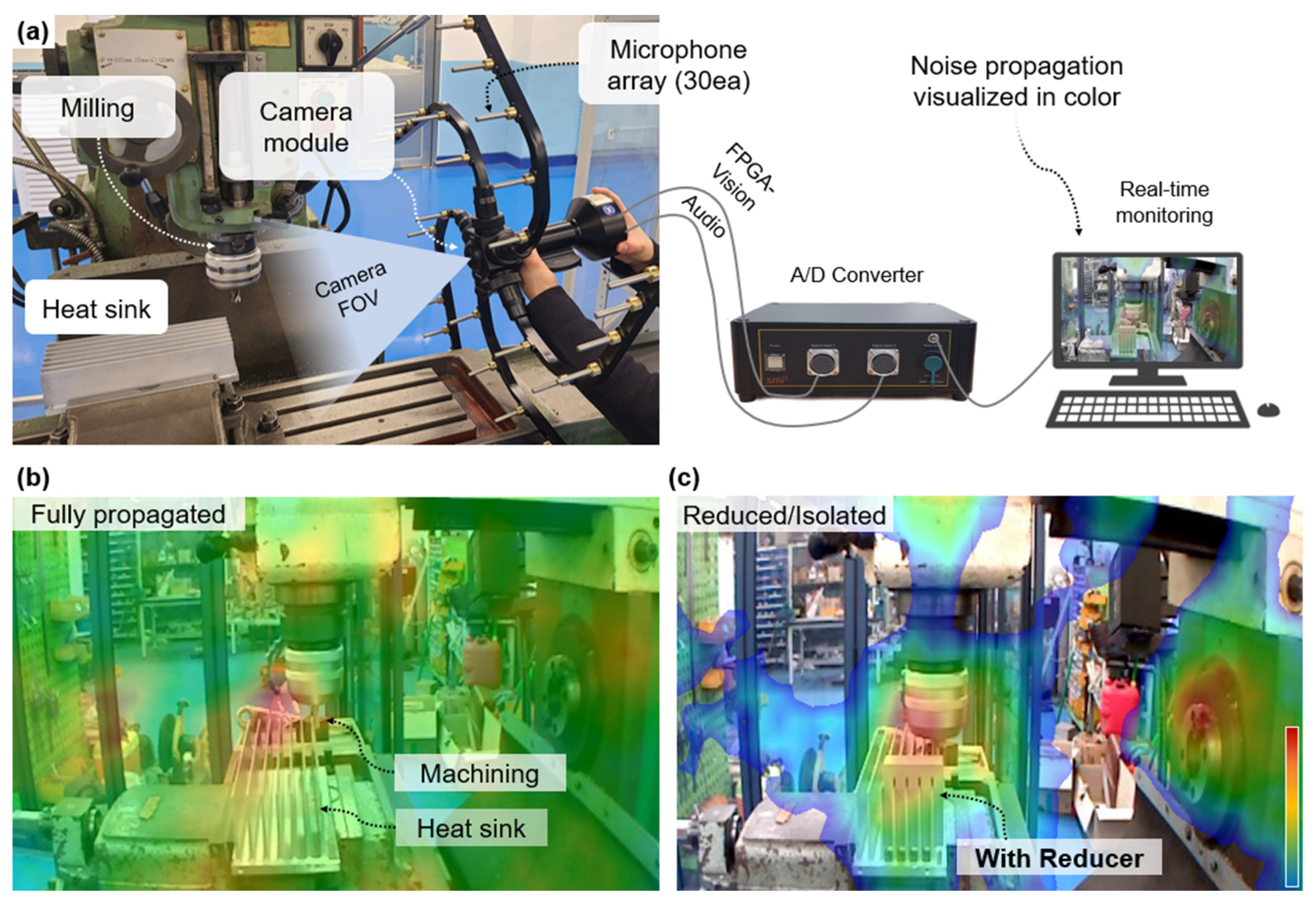
To verify the research, the reducer was demonstrated via visualization. As shown in Figure 11a, the effect of the reducer was measured and examined using an acoustic camera. The acoustic camera had an array of 30 microphones in a radial form and acquired sound pressure matching the field of view (FOV) range of the camera module on the center of the tool. The acoustic camera combines vision and audio data at high speed through FPGA beamforming. The location and level of sound pressure were precisely calculated and transmitted to the video screen in real time through data processing. As a result, the area of noise propagation and the sound pressure transmitted through the air could be graphically demonstrated.
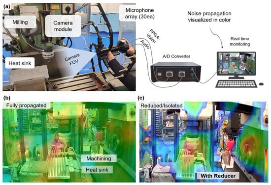
Figure 11.
Effectiveness visualization: (a) acoustic camera for real-time visualization of noise produced by milling machining; (b) fully propagated noise without reducer; (c) diminished noise and isolation with the printed reducer.
Figure 11b visualizes the propagation of sound pressure in an actual machining environment using the acoustic camera. The FOV included a milling machine, heat sink, and reducer. The distance between the acoustic camera and the workpiece was 153 mm, sufficient for detecting the sound pressure in the atmosphere. The rotation speed of the milling tool was set to 1200 rpm. During milling on the heat sink, the red area indicates that high sound pressure appeared between the fins and at the contact with the mill. According to a study in the literature on milling, chatter generated from the workpiece causes the machining system to lose dynamic stability, resulting in large amplitude vibration and noise [26]. The vibration is transmitted to the fins. The fins with multiple large areas effectively dissipate the noise in more diverse directions. The green area indicates relatively low sound pressure, meaning that the noise was still dispersed and transmitted to the surroundings. The noise was propagated throughout the FOV, which meant that the vibration was evenly transmitted via the air.
Figure 11c shows the remarkable reducer. There are two red islands in the image. Significant acoustic pressure was still generated at the contact point between the milling tool and the heat sink. However, the amplified intensity was reduced as the red island became blurred. Unlike in the experiment without the reducer, the acoustic propagation was reduced because the reducer controlled the isolation. On the right side of the image, the noise generation in the milling machine body was due to the built-in high-power DC motor. As a result, the noise transmitted through the air was reduced, isolating the acoustic pressure within a certain region of the FOV. Therefore, there are regions where the color representing the sound is not layered on the image. The verification clearly supports the idea and simulation prediction that a reducer designed with a vibration control structure would reduce noise generation and suppress acoustic pressure propagation by impeding the vibration energy generated from the fin.
4. Conclusions
Sound is an important element in daily life, but when the sound pressure level exceeds a certain threshold, it can have harmful effects such as increased stress, accumulated fatigue, and damage to the auditory system. In manufacturing environments, noise can disrupt communication among workers, leading to collaboration and safety problems. Additionally, it may inconvenience nearby residents, potentially resulting in social conflicts. Therefore, noise control is a critical engineering element for protecting people.
In this study, we proposed a simple approach to prevent harmful noise. Theories, analyses, and experimental results support our idea. Facile 3D printing was used to fabricate a prototype of a vibration reducer. The fabricated reducer successfully reduced fin vibrations and blocked the propagation of noise. Then, the noise control was analyzed and verified through simulations and experiments. During the experiments, a sound level meter, vibration meter, and acoustic camera were used to visually and quantitatively analyze the acoustic behaviors. By adjusting the number and size of reducers, we optimized methods to improve noise reduction efficiency. As a result, noise with a sound pressure level of 93 dB was reduced to 74 dB, demonstrating that the proposed reducer design reduced harmful noise levels by approximately 20%.
Unlike conventional manufacturing methods, 3D printing enables rapid prototyping, structural customization, and low-cost production, making it highly applicable across various fields. This technology can be utilized in diverse environments, including education, residential, and urban spaces, contributing to the creation of safer and more comfortable surroundings. In conclusion, 3D printing-based vibration control technology demonstrates strong potential as a practical tool for environmental noise management. By combining structural innovation with economic manufacturability, it offers valuable contributions to research, industry, and urban environmental management.
Supplementary Materials
The following supporting information can be downloaded at: https://drive.google.com/file/d/1zr-nnAaBedxR7g-05UpY0h80oardKqCR/view?pli=1, Video S1: Heat sink machining with reducer.
Author Contributions
All authors contributed to the study’s conception and design. S.L. conducted experimental research. H.C. created a design concept that allowed us to incorporate mechanical technology into materials and design. J.K. designed the overall study and experiments. J.K. supervised the project. All authors have read and agreed to the published version of the manuscript.
Funding
This research was supported by the Bisa Research Grant of Keimyung University No. 20230193.
Data Availability Statement
The original contributions presented in this study are included in the article/Supplementary Materials. Further inquiries can be directed to the corresponding author.
Conflicts of Interest
All authors certify that they have no affiliations with or involvement in any organization or entity with any financial interest or non-financial interest in the subject matter or materials discussed in this manuscript.
References
- Cho, S.; Lim, D.Y.; Kim, S.; Kim, H.; Kang, W.Y.; Park, W.J. Association between Occupational Noise Exposure and Insomnia among Night-Shift Production Workers: A 4-Year Follow-up Study. Noise Health 2023, 25, 135–142. [Google Scholar] [CrossRef] [PubMed]
- Tsalera, E.; Papadakis, A.; Samarakou, M. Monitoring, profiling and classification of urban environmental noise using sound characteristics and the KNN algorithm. Energy Rep. 2020, 6, 223–230. [Google Scholar] [CrossRef]
- Samara, P.; Athanasopoulos, M.; Markatos, N.; Athanasopoulos, I. From sound waves to molecular and cellular mechanisms: Understanding noise-induced hearing loss and pioneering preventive approaches (Review). Med. Int. 2024, 4, 60. [Google Scholar] [CrossRef] [PubMed]
- Faisal, A.A.; Selen, L.P.J.; Wolpert, D.M. Noise in the nervous system. Nat. Rev. Neurosci. 2008, 9, 292–303. [Google Scholar] [CrossRef] [PubMed]
- Hahad, O.; Kuntic, M.; Al-Kindi, S.; Kuntic, I.; Gilan, D.; Petrowski, K.; Daiber, A.; Münzel, T. Noise and mental health: Evidence, mechanisms, and consequences. J. Expo. Sci. Environ. Epidemiol. 2025, 35, 16–23. [Google Scholar] [CrossRef]
- Jarvey, S.; Gouyaso, H. The Influence of Earphone Usage Behaviour on Ear Disorders. J. La Medihealtico 2021, 2, 10–15. [Google Scholar] [CrossRef]
- Karami, M.; Aliabadi, M.; Golmohammadi, R.; Hamidi Nahrani, M. The effect of hearing protection devices on speech intelligibility of Persian employees. BMC Res. Notes 2020, 13, 4–9. [Google Scholar] [CrossRef]
- Seol, H.Y.; Kim, S.H.; Kim, G.Y.; Jo, M.; Cho, Y.S.; Hong, S.H.; Moon, I.J. Influence of the Noise-Canceling Technology on How We Hear Sounds. Healthcare 2022, 10, 1449. [Google Scholar] [CrossRef]
- Li, J.; Yang, L. Recent Development of Heat Sink and Related Design Methods. Energies 2023, 16, 7133. [Google Scholar] [CrossRef]
- Nazzal, I.T.; Salem, T.K.; Al Doury, R.R.J. Theoretical Investigation of a Pin Fin Heat Sink Performance for Electronic Cooling using Different Alloys Materials. IOP Conf. Ser. Mater. Sci. Eng. 2021, 1094, 012087. [Google Scholar] [CrossRef]
- Feng, F.; Lian, Y.; Wang, J.; Song, J.; Yan, B.; Liu, X. Mechanical Properties and Thermal Shock Performance of High-Energy-Rate-Forged W-1%TaC Alloy. Crystals 2022, 12, 1047. [Google Scholar] [CrossRef]
- Wei, W.; Shang, Y.; Peng, Y.; Cong, R. Research Progress of Noise in High-Speed Cutting Machining. Sensors 2022, 22, 3851. [Google Scholar] [CrossRef] [PubMed]
- Sambucci, M.; Valente, M. Acoustic behaviour of 3d-printable cement mortars functionalized with recycled tire rubber aggregates. In “Advances in Acoustics, Noise and Vibration-2021”, Proceedings of the 27th International Congress on Sound and Vibration, ICSV, Online, 11–16 July 2021; Silesian University Press: Katowice, Poland, 2021; pp. 1–9. [Google Scholar]
- Qiu, Y.; Xu, W.; Hu, Z.; Fu, J.; He, M. Review of Lightweight Vibration Isolation Technologies for Marine Power Devices. Shock. Vib. 2024, 2024, 1076935. [Google Scholar] [CrossRef]
- Yang, Z.; He, X.; Li, B.; Atrens, A.; Yang, X.; Cheng, H. Influence of Si, Cu, B, and Trace Alloying Elements on the Conductivity of the Al-Si-Cu Alloy. Materials 2022, 15, 426. [Google Scholar] [CrossRef]
- Yadav, P.K.; Abhishek Singh, K.; Bhaskar, J. Effect of Infill Percentage on Vibration Characteristic of 3D-Printed Structure. In Advances in Manufacturing and Industrial Engineering; Lecture Notes in Mechanical Engineering; Springer: Singapore, 2021; pp. 565–573. [Google Scholar] [CrossRef]
- Rasangika, A.H.D.K.; Nasif, M.S.; Pao, W.; Al-Waked, R. Effect of fin spacing on the vibration-assisted thermal performance of heat sink. IOP Conf. Ser. Earth Environ. Sci. 2023, 1281, 012059. [Google Scholar] [CrossRef]
- Vilagosh, Z.; Lajevardipour, A.; Wood, A. Computer simulation study of the penetration of pulsed 30, 60 and 90 GHz radiation into the human ear. Sci. Rep. 2020, 10, 1479. [Google Scholar] [CrossRef]
- Wood, G.S.; Newton, M.J.; Lomax, P.; Cheung, R.; Wood, G.S.; Newton, M.J.; Lomax, P. Graphene-based capacitive monolithic microphone with optimized air gap thickness and damping. J. Vac. Sci. Technol. B 2024, 42, 063002. [Google Scholar] [CrossRef]
- Hossseinabadi, M.T.; Sani, S.M.T.; Bahmanpour, H.; Fahiminejad, A. Measurement of sound level in sport natural areas using the maintaining athletes’ health approach. Ann. Appl. Sport Sci. 2020, 10. [Google Scholar] [CrossRef]
- Hu, Y.; Li, S.; Deng, X.; Vadim, S. Correlation analysis of noise sound pressure and vibration in aluminum alloy milling. JVC/J. Vib. Control 2022, 28, 276–289. [Google Scholar] [CrossRef]
- Dunaj, P.; Berczyński, S.; Miadlicki, K.; Irska, I.; Niesterowicz, B. Increasing damping of thin-walled structures using additively manufactured vibration eliminators. Materials 2020, 13, 2125. [Google Scholar] [CrossRef]
- Botean, A.I. Thermal expansion coefficient determination of polylactic acid using digital image correlation. E3S Web Conf. 2018, 32, 01007. [Google Scholar] [CrossRef]
- He, F.; Ning, H.; Khan, M. Effect of 3D Printing Process Parameters on Damping Characteristic of Cantilever Beams Fabricated Using Material Extrusion. Polymers 2023, 15, 257. [Google Scholar] [CrossRef] [PubMed]
- Jiang, T.; Wang, Y.; Xu, J.; Yu, H. Study on Sound Absorption Performance of Aluminum Foam Combination. J. Phys. Conf. Ser. 2023, 2499, 012003. [Google Scholar] [CrossRef]
- Janousek, M.K.B.; Xu, D.; Vazhapilli Sureshbabu, A.; Zimmermann, M. Vibration Reduction By Tuned Mass Dampers Inside Cavities of Topology Optimized Lattice Structures. Proc. Des. Soc. 2023, 3, 3791–3799. [Google Scholar] [CrossRef]


Disclaimer/Publisher’s Note: The statements, opinions and data contained in all publications are solely those of the individual author(s) and contributor(s) and not of MDPI and/or the editor(s). MDPI and/or the editor(s) disclaim responsibility for any injury to people or property resulting from any ideas, methods, instructions or products referred to in the content. |
© 2025 by the authors. Licensee MDPI, Basel, Switzerland. This article is an open access article distributed under the terms and conditions of the Creative Commons Attribution (CC BY) license (https://creativecommons.org/licenses/by/4.0/).