Article

Effect of Key Parameters on Ploughing Force Performance of Planing-Type Anti-Climbers

1
Zhan Tianyou College, Dalian Jiaotong University, Dalian 116028, China
2
School of Mechanical Engineering, Dalian Jiaotong University, Dalian 116028, China
3
R&D Center, CRRC Tangshan Co., Ltd., Tangshan 064000, China
*
Author to whom correspondence should be addressed.
Machines 2025, 13(5), 353; https://doi.org/10.3390/machines13050353
Submission received: 31 March 2025 / Revised: 22 April 2025 / Accepted: 23 April 2025 / Published: 24 April 2025
(This article belongs to the Section Machine Design and Theory)

Abstract

:
This paper proposes a mathematical model-based analytical approach to address the cutting force prediction and performance optimization challenges in planing-type anti-climbers for high-speed train passive safety systems. The method overcomes the reliance on experimental calibration inherent to conventional approaches, enabling the efficient quantitative evaluation of anti-climber cutting performance. By equivalently modeling the collision energy dissipation process as an orthogonal cutting model, a theoretical framework integrating material dynamic response characteristics and impact boundary conditions was developed for direct cutting force prediction without experimental calibration. Finite element modeling implemented on the ABAQUS platform was employed for simulation analysis, supplemented by dynamic impact tests for validation. The results demonstrate that the model achieves ≤15% relative error compared with the simulation data and ≤5% deviation from the experimental measurements, confirming its engineering applicability. Sensitivity analysis reveals that cutting depth exhibits the most pronounced positive correlation with cutting force, while increased tool rake angle reduces cutting force. The dynamic equilibrium between thermal softening effects and strain rate strengthening leads to cutting force reduction with elevated cutting speed. This research establishes theoretical and technical foundations for the intelligent optimization of passive safety systems in rail transit equipment.

1. Introduction

With the rapid advancement of high-speed railway technology, the continuous increase in train operational speeds has imposed higher requirements on passive safety performance. In train collision accidents, how to effectively absorb impact energy, mitigate structural damage, and ensure passenger safety are among the core challenges in rail transit equipment development [1]. As a critical component of train passive safety systems, anti-climbers primarily function by converting collision kinetic energy into thermal energy or plastic work through controlled plastic deformation and energy dissipation mechanisms, thereby suppressing impact force transmission pathways and preserving the integrity of the main car body structure and passenger compartments [2]. Among these, planing-type anti-climbers have emerged as a research focus in high-speed train collision protection due to their advantages of high energy absorption efficiency, design repeatability, and structural compactness [3]. However, the optimization of their cutting performance heavily relies on accurate predictions of dynamic cutting force characteristics [4]. Inherent complexities, including material nonlinearity, thermomechanical coupling effects, and tool–workpiece interfacial friction during cutting processes, pose significant challenges to traditional design methodologies [5]. Cutting force prediction is critical in the design of anti-climbers, as it serves as a key metric for evaluating energy absorption efficiency and structural dynamic stability. These factors directly influence the plastic deformation modes and energy dissipation pathways of anti-climbers. Prediction deviations may lead to insufficient energy absorption or localized stress concentrations, potentially triggering structural instability or even fracture, thereby jeopardizing passenger safety. Traditional methods relying on experimental calibration are costly and time-consuming, making them unsuitable for rapid iterations under complex working conditions. Consequently, developing high-precision cutting force prediction models with reduced experimental dependency is a technical prerequisite for enhancing passive safety performance and an urgent requirement for achieving intelligent design in rail transit equipment.
In recent years, domestic and international scholars have systematically investigated cutting force prediction models. Early empirical formula-based approaches simplified geometric relationships and mechanical equilibrium conditions to preliminarily reveal the influence of cutting parameters on cutting forces. However, their neglect of material dynamic response characteristics limited prediction accuracy [6]. With the widespread adoption of finite element simulation technology, numerical simulation-based cutting analysis has gradually become mainstream [7]. For instance, Yaich et al. (2020) employed a two-dimensional finite element model to elucidate the critical roles of mesh size and friction coefficients in thermomechanical coupling predictions for titanium alloy machining [8]. Nevertheless, such methods require the precise calibration of material constitutive parameters, and the acquisition of traditional Johnson–Cook (JC) model parameters still relies on split-Hopkinson pressure bar (SHPB) experiments, which incur high costs and hinder rapid engineering iteration.
To overcome these limitations, recent studies have focused on developing high-precision prediction frameworks with reduced experimental dependency. Dou et al. (2025) conducted parametric numerical studies on orthogonal cutting processes using the smoothed particle hydrodynamics (SPH) method, achieving 92% prediction accuracy for aluminum alloy cutting forces through coupled thermomechanical effects and material dynamic responses [9]. In complex material systems, Zan et al. (2024) compared the cutting performance of silicon carbide fiber-reinforced metal matrix composites, revealing that hardness variations in matrix materials could induce over 30% fluctuations in cutting forces, providing experimental foundations for multi-phase material cutting modeling [10]. Additionally, Boldyrev (2018) proposed a free orthogonal cutting simulation method based on Smoothed Particle Galerkin (SPG), enhancing computational efficiency by 40% through simplified contact algorithms, though the model’s adaptability to extreme strain rates requires further validation [11]. Fu et al. (2020) introduced crystal plasticity theory to establish an anisotropic aluminum alloy cutting model, offering theoretical support for nonlinear responses under complex loading conditions [12].
The evolution of cutting force prediction theory has progressed through three stages: empirical formulas, analytical models, and numerical simulations. In the 1940s, Merchant established the orthogonal cutting model based on the minimum energy principle, laying the foundation for classical mechanics. However, its assumption of materials as ideal rigid-plastic bodies and neglect of strain hardening and temperature effects resulted in significant errors in high-strain-rate scenarios. With advancements in computational technology, data-driven methods have gained prominence. Marani et al. (2020) developed a neuro-fuzzy prediction model that integrates cutting parameters and material properties to achieve simultaneous predictions of surface roughness and cutting forces, though its generalization capability is constrained by training data diversity [13]. In numerical algorithm optimization, Pantalé et al. (2022) proposed an improved Oxley analytical model-solving algorithm implemented via the Python 3.9.13 platform, enabling the efficient parametric analysis of orthogonal cutting processes and providing new tools for real-time predictions under complex working conditions [14].
Current cutting force prediction models face multiple challenges. First, their heavy reliance on experimental calibration leads to computational inefficiency and cost issues. Finite element simulation models are overly complex and computationally intensive, failing to meet rapid engineering iteration demands [15]. Second, early models inadequately addressed energy dissipation mechanisms under complex boundary conditions, resulting in insufficient adaptability to real-world scenarios [16]. Furthermore, there exists a pronounced disconnect between theoretical developments and engineering applications, characterized by a lack of customized design tools and validation systems constrained by single-method verification rather than multi-dimensional closed-loop validation [17].
To address these challenges, this study proposes a cutting force prediction model designed to eliminate dependence on experimental calibration and enable the efficient quantitative evaluation of planing-type anti-climber cutting performance.
The innovations of this research are threefold: (1) The introduction of mathematical modeling into cutting force prediction for planing-type anti-climbers, utilizing analytical methods to quantify the coupling effects between material dynamic responses and cutting parameters, thereby significantly reducing reliance on experimental data. (2) The development of a dual-loop validation strategy integrating simulation and physical experiments to balance computational efficiency with engineering accuracy, providing a reliable tool for anti-climber design under complex working conditions. (3) By revealing the impact patterns of cutting depth, tool rake angle, and speed on performance, this research offers specific design guidelines for creating planing-type anti-climbing devices that can efficiently absorb collision energy while maintaining structural stability. These contributions advance the intelligent upgrading of high-speed train passive safety technologies and demonstrate substantial academic value and engineering application prospects.

2. Cutting Force Prediction Model

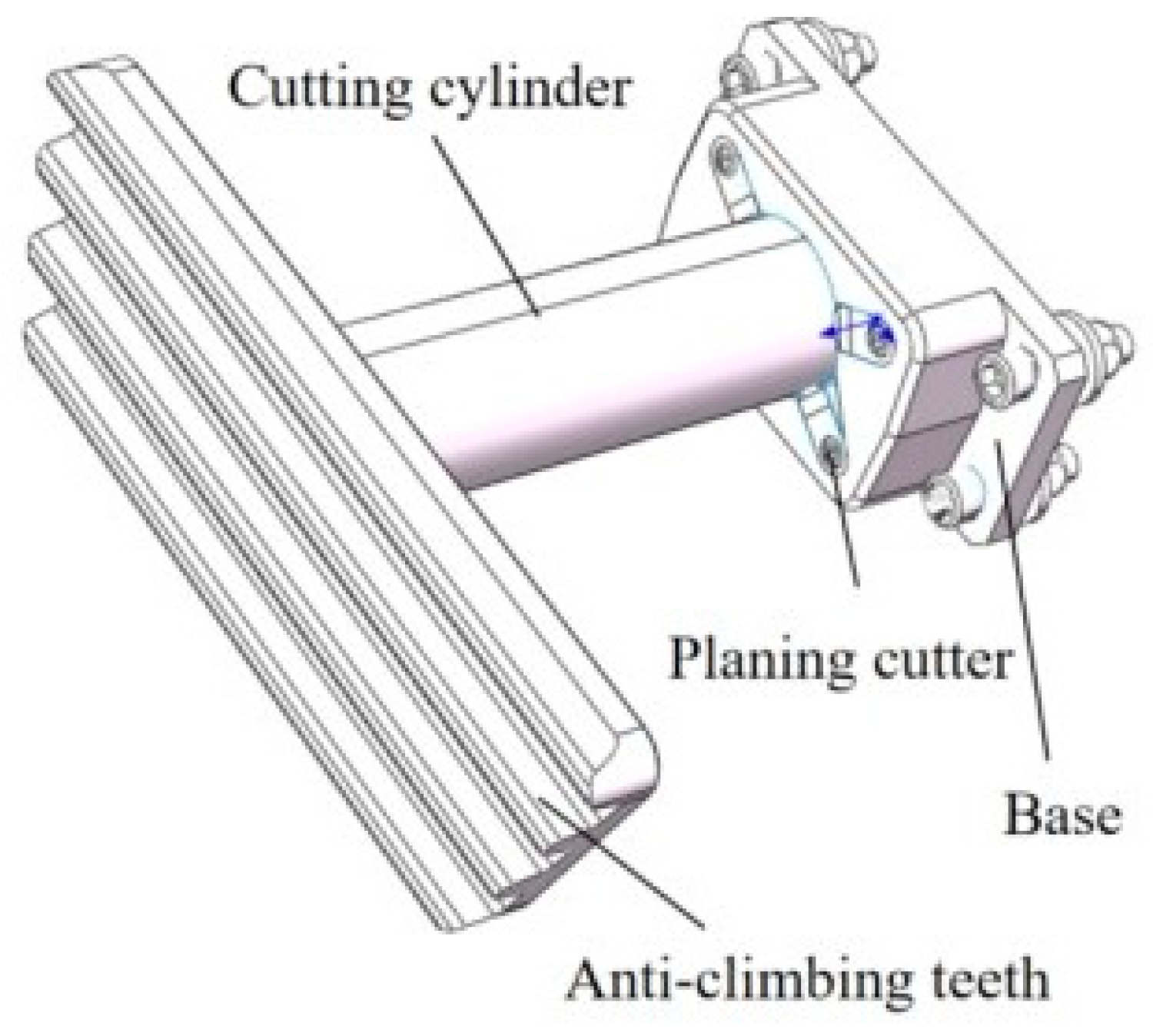
Having established the significance of planing-type anti-climbers and the limitations of existing research, this section focuses on the methodology for constructing a cutting force prediction model, which serves as the foundation for subsequent simulations and experimental validation. The planing-type anti-climber discussed in this study is primarily installed at the front and rear sections of trains. During collisions, the anti-climber absorbs substantial energy by inducing plastic deformation and the fracture of metallic materials through cutting, thereby effectively mitigating the transmission of impact forces to other vehicle components and safeguarding structural integrity and passenger safety.
As illustrated in Figure 1, which depicts the material cutting process by the anti-climber blade, the cutting mechanism can be identified as orthogonal cutting. Consequently, the cutting force prediction model for the planing-type anti-climber is formulated by simplifying the process to orthogonal cutting conditions.
The prediction of cutting forces Fc primarily relies on deriving these forces from shear forces Fs via geometric relationships. The governing equation is expressed as follows:
F C = F s cos β γ 0 cos + β γ 0
Here, γ 0 denotes the tool rake angle. To solve Fc, additional parameters including the shear force Fs, friction angle β , and shear angle must be determined.
Both β and can be obtained experimentally or via empirical formulas. This study adopts empirical formulas [18]:
= π 4 β 2 + γ 0 2
β = arctan f · V c P
The shear force Fs is proportional to the shear stress τ s , governed by the shear area. Let a represent the uncut chip thickness, b the cutting width, Ac the cross-sectional area of the undeformed chip, and As the primary shear plane area. The shear force is expressed as follows [19]:
F s = τ s · A s = τ s · a b · csc
To determine τ s , a constitutive model is required.
Metal cutting mechanisms have been investigated for decades, with researchers striving to establish generalized theoretical models capable of precisely predicting process parameters, thereby reducing reliance on experimental validation [20]. Despite inherent challenges—such as material fracture, thermomechanical coupling, and tool–chip interface friction—that introduce deviations in existing model predictions, these theoretical frameworks hold significant value in elucidating fundamental cutting principles and optimizing machining parameters [21]. Consequently, they serve as a cornerstone for advancing manufacturing technology innovation [22].
In this context, the Johnson–Cook (JC) constitutive model—a viscoplastic constitutive modeling approach with exceptional engineering applicability—has been widely adopted to characterize the dynamic mechanical response of metallic materials [23]. The model correlates flow stress with the coupled effects of strain, strain rate, and temperature through five measurable parameters (A, B, C, n, m). Its mathematical simplicity and straightforward parameter calibration make it particularly suitable for dynamic loading scenarios, such as cutting force prediction [24]. Although the JC model may exhibit limited accuracy in describing material softening behavior under high strain rates or extreme thermal conditions, its predictive capability has been continuously improved through parameter modifications and enhancements in multiphysics-coupled algorithms [25]. To date, it remains the preferred tool for analyzing metal behavior under impact loading.
The constitutive equation is formulated as follows:
τ = 1 3 [ A + B γ 3 n [ 1 + C l n ( γ ˙ γ 0 ) ] [ 1 ( T T r T m T r ) m ]
where τ is the shear stress, γ the shear strain, γ ˙ the shear strain rate, γ 0 ˙ the reference shear strain rate, T the instantaneous absolute temperature of the workpiece, Tr the initial temperature of the workpiece, and Tm the melting temperature of the workpiece. The parameters A (yield strength, MPa), B (hardening modulus, MPa), C (strain rate sensitivity coefficient), n (hardening exponent), and m (thermal softening exponent) are material-specific constants that must be experimentally determined [26].
The segmented power-law distribution method for shear strain rate is employed to derive the shear strain and shear strain rate at the initial shear line (y = 0), primary shear plane (y = kh), and terminal shear line (y = h) by assigning specific values to y. These quantities are expressed as follows:
γ = γ m ˙ ( q + 1 ) V s i n ( k h ) q y q + 1 y k h γ m ˙ ( q + 1 ) V s i n ( 1 k ) q h q ( h y ) q + 1 + h γ m ˙ ( q + 1 ) V s i n y > k h
γ ˙ = γ m ˙ ( k h ) q y k h γ m ˙ ( 1 k ) q h q ( h y ) q y > k h
In the equation above, γ m ˙ represents the maximum shear strain rate, k denotes the unequal division coefficient, h is the shear band thickness (which can be determined from chip thickness and is taken as 0.25 in this study), V indicates velocity, and q serves as a velocity characterization coefficient with values of 3 for low-speed conditions and 7 for high-speed conditions (here adopted as 7). By solving this formulation, the shear strain and shear strain rate on the primary shear plane can be obtained, specifically the shear stress when y = kh.
Both the maximum shear strain rate and unequal division coefficient can be determined through the boundary conditions of tangential velocity components at the initial and final shear lines. These parameters are mathematically expressed as follows:
γ m ˙ = ( q + 1 ) V cos γ 0 h cos ( γ 0 )
k = cos cos ( γ 0 ) cos γ 0
Based on the aforementioned equations and the intrinsic material properties, the shear stress distribution within the shear zone and the shear stress on the primary shear plane can be determined. Further substitution into the shear force calculation formula enables the prediction of cutting forces generated during orthogonal cutting.
After establishing the theoretical model, the subsequent analysis employs this model to investigate the influence patterns of various parameters on cutting forces under distinct machining conditions. The selected parameters for analysis include cutting speeds of 5.5 m/s and 6.94 m/s, depths of cut of 3 mm and 5 mm, and tool rake angles of 0 and 7, resulting in eight distinct combinations of machining conditions (as detailed in Table 1). These datasets encompass diverse machining scenarios, allowing rigorous validation of the model’s predictive accuracy through comparative analyses with subsequent simulation results and experimental measurements.
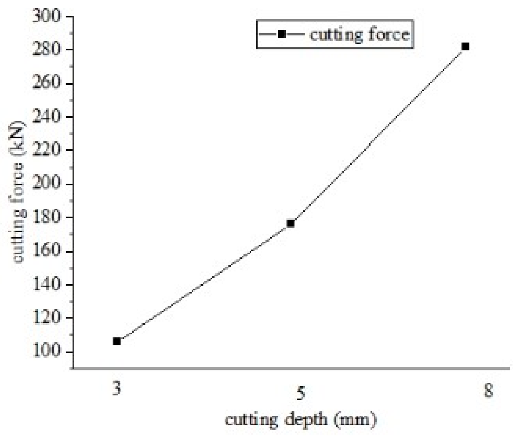
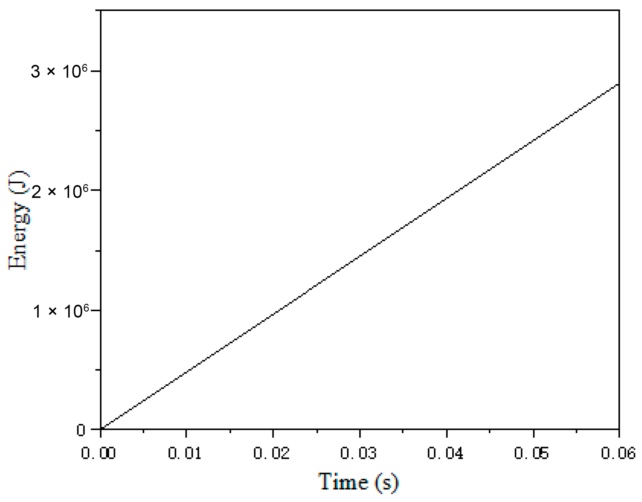
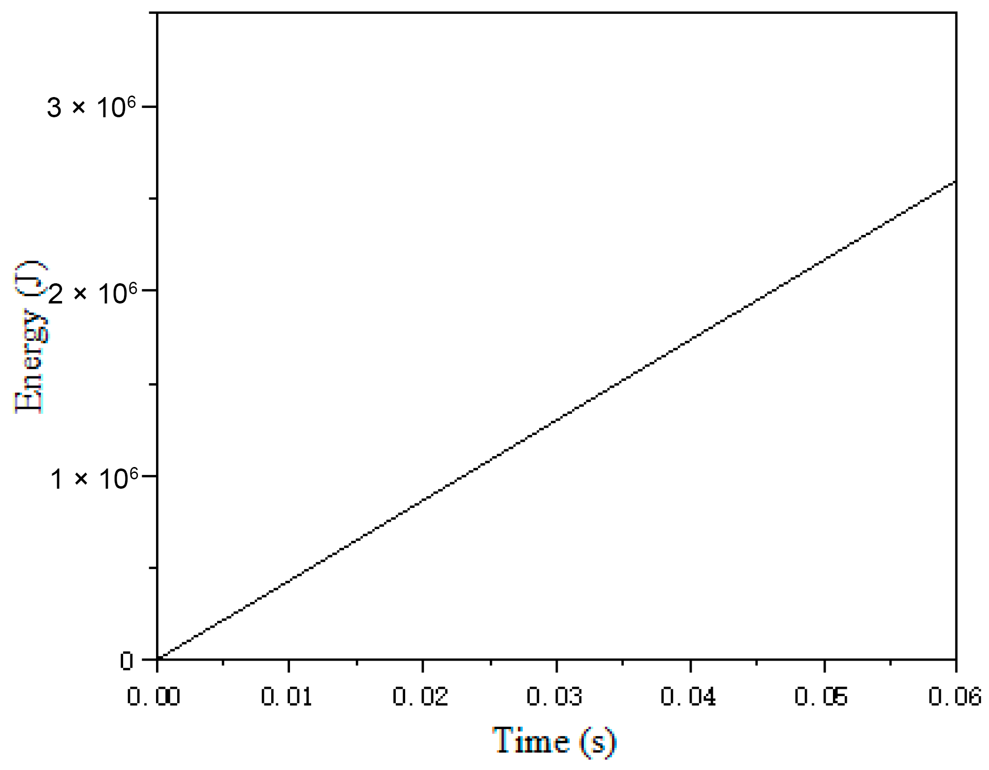
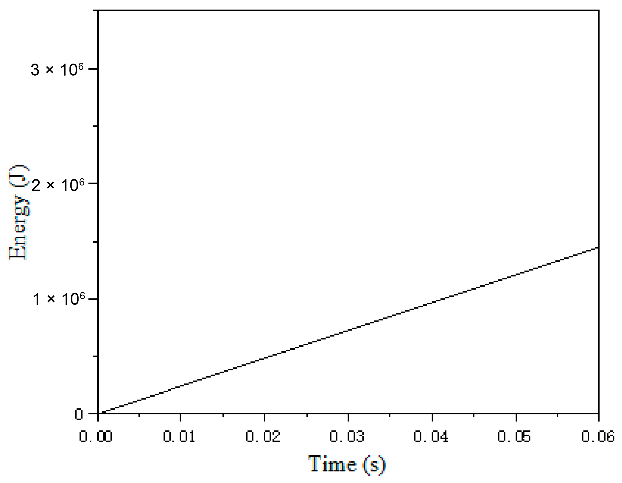
As indicated in the table, the cutting force exhibits a decreasing trend with an increase in tool rake angle. Similarly, a higher cutting speed correlates with a reduction in cutting force. To further analyze the effect of cutting depth, the model calculates cutting forces at depths of 3 mm, 5 mm, and 8 mm, yielding single-tool cutting forces of 105.62 kN, 176.03 kN, and 281.65 kN, respectively, as illustrated in Figure 2. This demonstrates that, under constant machining conditions, the cutting force increases proportionally with cutting depth.

3. Simulation Analysis

3.1. Model Establishment and Material Parameter Configuration

Building upon the theoretical framework above, this section employs simulation analysis to further investigate the performance of the planing-type anti-climbing device. The simulation provides intuitive results and serves as a reference for experimental validation. The studied planing energy-absorbing device adopts a modular integrated design, comprising a base, anti-climbing teeth, four tool arrays, and a planing cylinder, as illustrated in Figure 3. During collision events, impact loads are transmitted through the anti-climbing teeth to the planing cylinder, driving its axial movement along the tool arrays. The dynamic cutting interaction between the tools and the cylinder converts kinetic energy into plastic deformation energy and heat, achieving controlled energy dissipation.
Using SolidWorks 2024 software, a three-dimensional solid finite element model was constructed based on the dynamic explicit algorithm. The key geometric parameters are as follows: the total device length is 470 mm, the axial length of the energy-absorbing segment is 220 mm (inner diameter 80 mm/outer diameter 108 mm); the anti-climbing teeth dimensions are 280 mm × 140 mm × 35 mm; the geometric characteristics of the planing cylinder are Φ108 mm × 350 mm; the mounting base dimensions are 240 mm × 90 mm × 80 mm; and the cutting edge dimensions of the tool are 25 mm × 27 mm. The model strictly adheres to engineering design specifications, fully reproducing the mechanical response characteristics of the energy-absorbing structure.
The tools are secured using M10 hex socket countersunk head screws. The overall surface roughness of the tools is Ra3.2, with dimensional and angular tolerances complying with GB/T 1804-m [27]. A tool clearance angle of 6° is implemented. Tool dimensions are shown in Figure 4.
In explicit dynamics simulations, the meshing strategy directly affects the reliability of the results and the efficiency of computational resource use. For the planing-type anti-climbing device’s collision energy absorption, a hybrid-element modeling strategy based on functional partitioning was proposed, as shown in Figure 5. For the core energy-absorbing component, the planing cylinder, hexahedral reduced-integration elements were used. Their regular topology precisely captures stress gradient changes during large plastic deformations. Parametric optimization identified the optimal element size range for the workpiece as 1–2 mm. To prioritize computational accuracy, a refined element size of 1 mm (with 1,869,025 elements) was adopted. Tools, treated as rigid bodies, used tetrahedral linear elements with a size of 3 mm (6250 elements) to balance contact stability and efficiency. Other support parts had a mesh size of 5 mm. Numerical experiments indicated that hexahedral elements have higher integration point density than tetrahedral elements of the same size, reducing prediction errors in plastic strain. Hourglass energy control techniques were applied to suppress non-physical deformation modes.
For the geometrically complex connection area between the anti-climbing teeth and base, local mesh refinement was implemented. The mesh size was reduced from 5 mm to 3 mm in this region, with gradient transitions ensuring the seamless integration of different-sized elements and avoiding stress singularities. Additionally, boundary layer mesh refinement was applied to the cutting edges based on the curvature analysis of the tool–workpiece contact interface, enhancing the simulation accuracy of chip formation. Comparisons showed that reducing the energy-absorbing tube’s element size from 2 mm to 1 mm reduced fluctuations in cutting force predictions, confirming the effectiveness of the meshing strategy.
The metal cutting energy absorption process involves intricate elastoplastic transitions and thermomechanical coupling effects, where precise material constitutive models form the cornerstone of simulation reliability. During cutting operations, transient high temperatures and strain rates arise at the tool–workpiece interface, imposing stringent demands on the dynamic response characterization capabilities of material models. To address functional requirements, this study implements differentiated material selection: Q345B steel is adopted for the energy-absorbing tube, as its balanced yield strength and elongation optimize both plastic deformation capacity and structural stability; YG20C cemented carbide is selected for the tools, leveraging its elevated-temperature hardness and bending strength to ensure the geometric integrity of cutting edges under extreme operating conditions. As detailed in Table 2, critical constitutive parameters of the Q345B workpiece—including Young’s modulus, Poisson’s ratio, and thermal conductivity—are acquired through quasi-static tensile testing and dynamic split-Hopkinson pressure bar (SHPB) experiments. These parameters provide robust data support for numerical simulations, enabling the accurate replication of material behavior under coupled thermal–mechanical loads.

3.2. Simulation Analysis Process

An explicit dynamics simulation model of the planing-type anti-climbing device was established based on the ABAQUS platform. In the analysis step setup, the total simulation duration of 0.06 s was determined by the tool velocity and the effective stroke of the energy-absorbing tube. To enhance computational efficiency, a mass scaling technique was employed to increase the stable time increment by an order of magnitude, while mesh convergence verification ensured that the ratio of kinetic energy to internal energy remained below 5%, satisfying the energy conservation criteria for explicit dynamics.
For contact algorithms, the tool–energy-absorbing tube interface was defined as surface-to-surface penalty contact. Based on experimental calibration values for dry friction between cemented carbide and steel, a tangential friction coefficient of 0.2 was adopted, and normal behavior followed the hard contact criterion to prevent penetration. To accurately capture stress variations at the cutting interface, local mesh refinement was applied to the tool cutting edges and the plastic deformation zones of the energy-absorbing tube. Independent node sets were established to output localized stress data. The initial temperature field was set to the ambient temperature of 25 °C, with heat diffusion during cutting simulated through thermal conductivity coefficients and frictional heat generation rates. The simulation contour plots at 0 s, 0.03 s, and 0.06 s are presented in Figure 6, Figure 7 and Figure 8, respectively.
To investigate parameter sensitivity, a full-factorial experimental matrix was constructed with the following variables: number of tools (2/4), cutting depth (3 mm/5 mm), and tool rake angle (0°/7°), yielding a total of eight operating conditions. Under a cutting speed of 5.55 m/s, four representative cases were selected for dynamic energy accumulation process analysis. The time–energy curves for these four cases are illustrated in Figure 9, Figure 10, Figure 11 and Figure 12, respectively.
To further investigate the influence of different parameter combinations on single-tool cutting forces, the simulation results of four representative operating conditions under a cutting speed of 5.55 m/s are compared with predicted values in Figure 13, Figure 14, Figure 15 and Figure 16. The analysis of variance reveals that cutting depth has the greatest contribution to the peak planing force, while the tool rake angle primarily affects the stability of the cutting force. This indicates that deeper cuts induce higher resistance due to increased material engagement, whereas larger rake angles enhance cutting efficiency by reducing frictional interactions and promoting smoother chip flow.
The discrepancies between the experimental data and predicted data were calculated and are summarized in Table 3. The relative error was calculated using the following formula:
Relative Error (%) = (∣Simulation Data − Predicted Data∣Simulation Data) × 100% (Simulation Data∣Simulation Data − Predicted Data∣) × 100%.
The results indicate a high consistency between the two datasets, with relative errors between the model-predicted cutting forces and simulation-derived values remaining within 15%, which is acceptable in engineering practice. However, the simulation results also exhibit certain limitations. Therefore, further experimental validation is required. By comparing experimental measurements with simulation outcomes, the accuracy and reliability of the model can be more comprehensively evaluated.

4. Experimental Verification

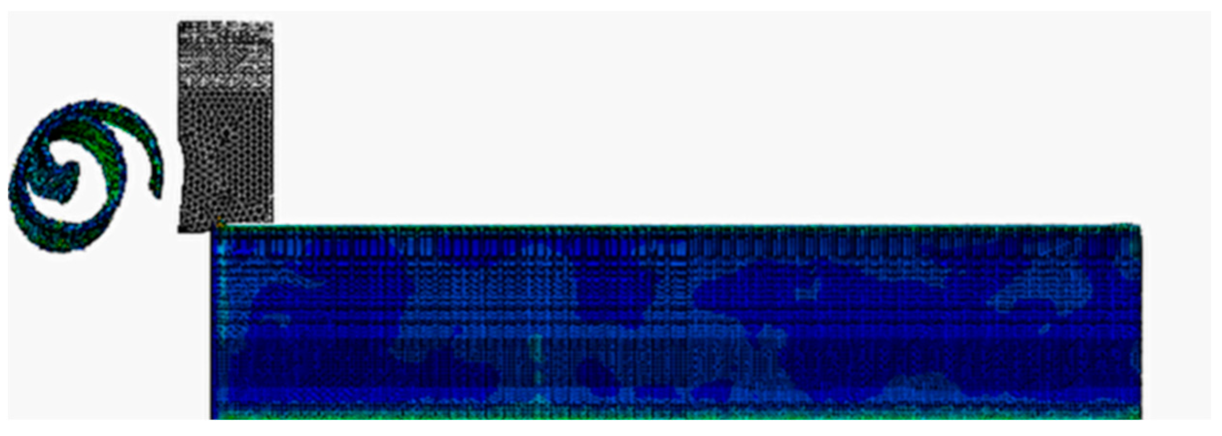
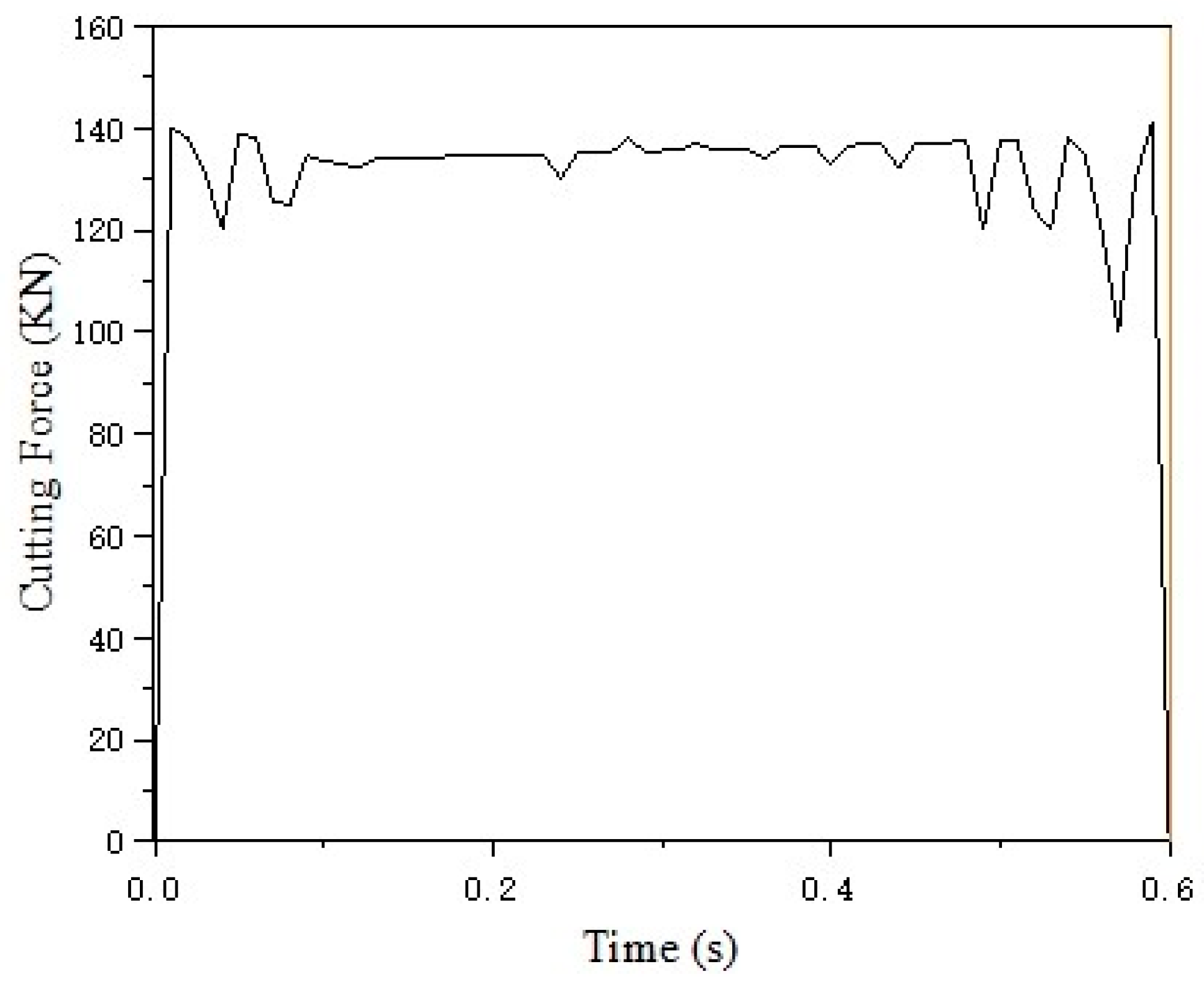
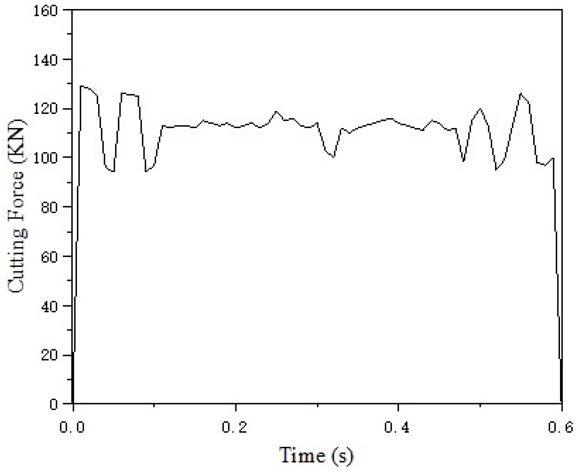
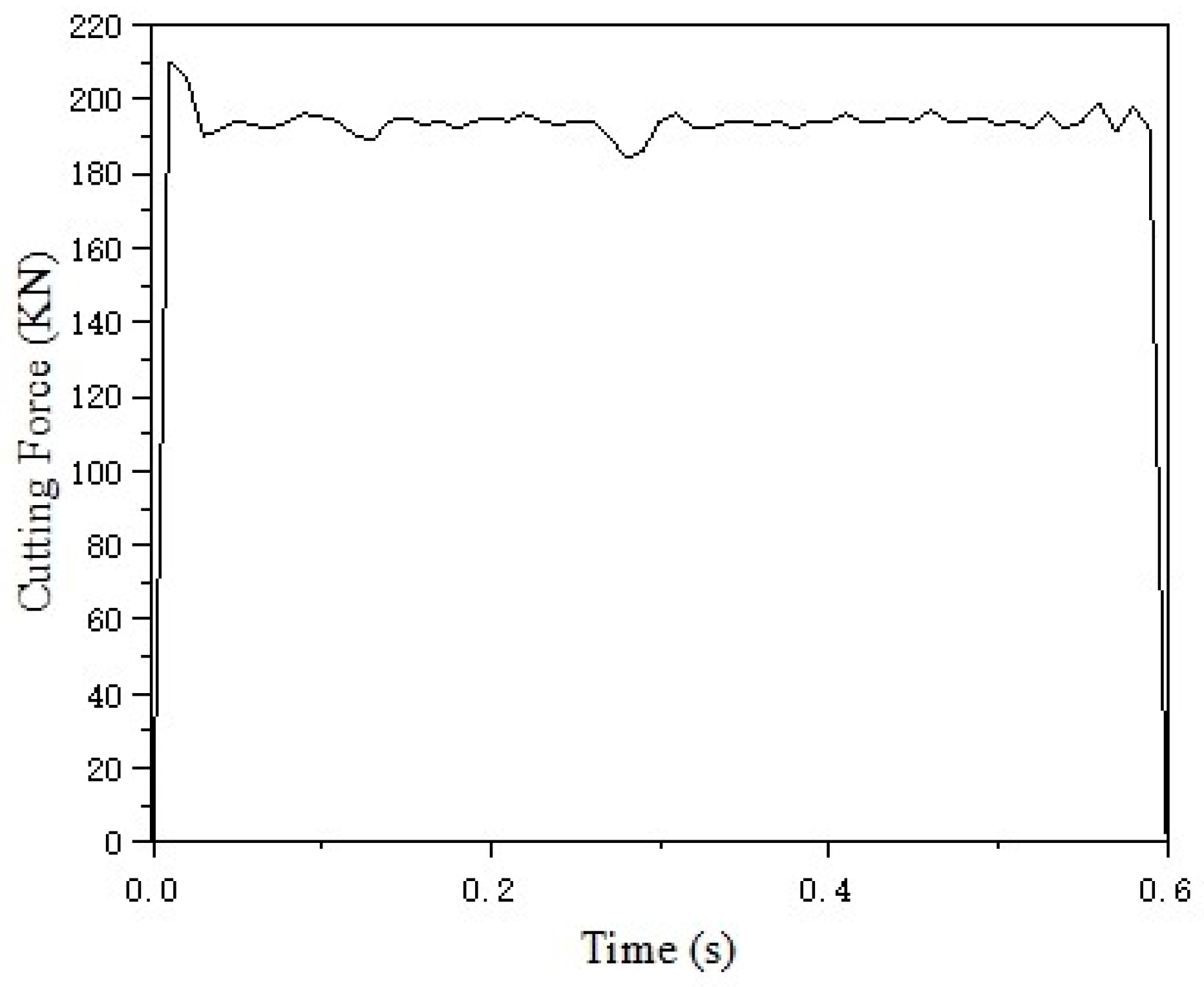
To verify the accuracy of the theoretical model and simulation analysis, experimental validation was conducted to provide robust evidence for the model’s reliability. Based on impact testing standards, this study established a validation framework for the cutting force prediction model, employing a dual-loop verification strategy integrating physical experiments and numerical simulations. The experimental platform incorporates a 13-ton counterweight sled, a high-speed hydraulic drive module, and a multi-dimensional sensor array, enabling the precise reproduction of train collision scenarios with a defined initial impact velocity against a rigid barrier. The core of the system is a modular cutting unit equipped with a tool angle adjustment mechanism and a closed-loop tool feed depth control system, achieving the precise parametric control of cutting depth and rake angle.
A high-speed NAC MEMRECAM HX-3 camera system at 4000 Hz was used to capture and analyze the structural deformation process. Six KISTLER piezoelectric load sensors were employed as the load-sensing elements. To eliminate boundary effects, the geometric parameters of the energy-absorbing tube strictly matched the simulation model: wall thickness of 6 mm and effective stroke of 220 mm. The tool assembly utilized YG20C cemented carbide, whose fine-grained microstructure ensures excellent resistance to thermal degradation, maintaining geometric integrity under complex stress states. The energy-absorbing tube was fabricated from a Q345B cold-drawn seamless steel tube. The experimental results are presented in Figure 17.
Some results are as follows: At a cutting depth of 4 mm and speed of 4.86 m/s, the cutting force was 548 kN. At a cutting depth of 5 mm and speed of 4.15 m/s, it was 427 kN. At a cutting depth of 6 mm, the cutting force was 1100 kN at 2.81 m/s, and 930 kN at 5.6 m/s. At 5.8 m/s, the cutting force dropped from 1400 kN to 840 kN due to tool breakage. Two typical tests were chosen to compare the experimental and simulation data from the finite element analysis, as shown in Table 4.
By inputting the measured boundary conditions into the cutting force prediction model established in this paper, the relative error between the model-predicted cutting forces and the experimentally measured values, as shown in Table 5, is maintained below 5%, which is acceptable in engineering practice. This indicates that the cutting force model proposed in this paper is not only theoretically sound, but also effective and reliable in practical applications.

5. Conclusions

This study systematically investigates the energy dissipation mechanisms and performance optimization strategies of planing-type anti-climbing devices under dynamic collisions by establishing a cutting force prediction model. Grounded in orthogonal cutting theory and integrating material dynamic response characteristics with impact boundary conditions, an analytical model capable of directly predicting cutting forces without experimental calibration is proposed. The model’s reliability and engineering applicability are validated through theoretical calculations, finite element simulations, and dynamic impact tests. The relative errors between theoretical predictions and simulation results remain within 15%, while deviations from experimental measurements are below 5%, significantly reducing reliance on extensive empirical validation in traditional development processes. This provides an efficient quantitative tool for the customized design of high-speed train anti-climbing devices.
Based on the findings of this study, the following parameter optimization strategies are proposed:
  • Priority adjustment of cutting depth: Appropriately increasing the cutting depth under structural stability constraints significantly enhances energy absorption efficiency. However, excessive plastic deformation leading to structural failure must be avoided.
  • Selection of tool rake angle: Larger rake angles effectively reduce cutting forces, making them suitable for impact load-sensitive scenarios. This requires durability validation considering the strength of tool materials.
  • Velocity threshold management: Elevated cutting speeds induce a dynamic equilibrium between thermal softening effects and strain rate strengthening, resulting in reduced cutting forces. Under high-speed conditions, thermomechanical coupling analysis should balance these effects to prevent material property degradation caused by excessive temperatures.
However, the current model exhibits limitations in characterizing extreme thermal softening effects and multi-axis asymmetric loads. Future studies should optimize the predictive framework by coupling oblique cutting models or incorporating crystal plasticity theories. Additionally, the influence of anisotropic texture effects in cold-drawn steel tubes on cutting forces remains insufficiently explored. Further investigation into this mechanism is essential to provide comprehensive theoretical support for complex material dynamic responses.
By integrating theoretical modeling, simulation analysis, and experimental validation, this study elucidates the energy absorption mechanisms and performance modulation principles of planing-type anti-climbing devices. The proposed cutting force prediction model balances engineering applicability and computational efficiency, providing critical theoretical and practical foundations for passive safety design in high-speed trains. These advancements lay the groundwork for evolving rail transit equipment toward enhanced safety and intelligence, driving technological progress in the field.

Author Contributions

Z.L. developed the simulation model and wrote the paper, performed the experimental data analysis, and plotted the graphs; J.F. checked the manuscript—review and supervision; C.Z. performed the experiments and analyzed the data; and H.H., D.S. and C.L. performed the data collection. All authors have read and agreed to the published version of the manuscript.

Funding

This research was funded by National Natural Science Foundation Youth Science Fund project (No. 52305449), Scientific research project of Education Department of Liaoning Province (No. LJKQZ20222336), and Natural Science Foundation of Liaoning Province (No. 2024-MS-169).

Data Availability Statement

Data are contained within the article.

Conflicts of Interest

Chong Zhang is employed by the R&D Center, CRRC Tangshan Co., Ltd. The remaining authors state that the study was conducted without any business or financial relationships. The remaining authors have no conflicts of interest.

References

  1. Pratiknyo, Y.B.; Setiawan, R.; Wayan Suweca, I. Experimental and theoretical investigation of combined expansion tube-axial splitting as impact energy absorbers. Int. J. Struct. Stab. Dyn. 2020, 20, 2050021. [Google Scholar] [CrossRef]
  2. He, Y.; Bi, Z.; Wang, T.; Wang, L.; Lu, G.; Cui, Y.; Tse, K.M. Design and mechanical properties analysis of hexagonal perforated honeycomb metamaterial. Int. J. Mech. Sci. 2024, 270, 109091. [Google Scholar] [CrossRef]
  3. Guo, W.; Yang, C.; Xu, P.; Yang, L.; Wen, Y.; Jin, X. Crashworthiness optimization for cutting energy-absorbing structures based on the multiobjective G-CBW method. Alex. Eng. J. 2023, 72, 363–383. [Google Scholar] [CrossRef]
  4. Guan, W.; Gao, G.; Li, J.; Yu, Y. Crushing analysis and multi-objective optimization of a cutting aluminium tube absorber for railway vehicles under quasi-static loading. Thin-Walled Struct. 2018, 123, 395–408. [Google Scholar] [CrossRef]
  5. Li, Y.; Zhang, H.; Xie, J.; Xiao, S.; Zhu, T.; Zhou, G.; Xu, L. Energy Absorption Characteristics and Parameter Optimization of Anti-Climb Energy-Absorbing Devices for Subway Vehicles under Impact Loads. Appl. Sci. 2024, 14, 5203. [Google Scholar] [CrossRef]
  6. Rahman, M.; Wang, Z.G.; Wong, Y.S. A review on high-speed machining of titanium alloys. JSME Int. J. Ser. C Mech. Syst. Mach. Elem. Manuf. 2006, 49, 11–20. [Google Scholar] [CrossRef]
  7. Saffar, R.J.; Razfar, M.R.; Zarei, O.; Ghassemieh, E. Simulation of three-dimension cutting force and tool deflection in the end milling operation based on finite element method. Simul. Model. Pract. Theory 2008, 16, 1677–1688. [Google Scholar] [CrossRef]
  8. Yaich, M.; Ayed, Y.; Bouaziz, Z.; Germain, G. A 2D finite element analysis of the effect of numerical parameters on the reliability of Ti6Al4V machining modeling. Mach. Sci. Technol. 2020, 24, 509–543. [Google Scholar] [CrossRef]
  9. Dou, W.; Yu, K.; Yao, S.; Geng, X.; Yu, G. Experimental and parametric numerical study of the orthogonal metal cutting using the smoothed particle hydrodynamics method. Part. Sci. Technol. 2025, 43, 357–368. [Google Scholar] [CrossRef]
  10. Zan, S.; Liao, Z.; Mypati, O.; Axinte, D.; M’Saoubi, R.; Walsh, M.; Robles-Linares, J.A. Machining SiC fibre reinforced metal matrix composites–How do different matrix materials affect the cutting performance. CIRP Ann. 2024, 73, 53–56. [Google Scholar] [CrossRef]
  11. Boldyrev, I.S. SPG simulation of free orthogonal cutting for cutting forces prediction. In Proceedings of the International Conference on Industrial Engineering, Moscow, Russia, 15–18 May 2018; pp. 1695–1700. [Google Scholar]
  12. Fu, X.; Zhou, B.; Meng, Y.; Pan, Y. Study on the constitutive model of anisotropic aluminum alloy in high speed cutting. Mach. Sci. Technol. 2020, 24, 906–923. [Google Scholar] [CrossRef]
  13. Marani, M.; Songmene, V.; Zeinali, M.; Kouam, J.; Zedan, Y. Neuro-fuzzy predictive model for surface roughness and cutting force of machined Al–20 Mg 2 Si–2Cu metal matrix composite using additives. Neural Comput. Appl. 2020, 32, 8115–8126. [Google Scholar] [CrossRef]
  14. Pantalé, O.; Dawoua Kaoutoing, M.; Houé Ngouna, R. A New Algorithm to Solve the Extended-Oxley Analytical Model of Orthogonal Metal Cutting in Python. Appl. Mech. 2022, 3, 889–904. [Google Scholar] [CrossRef]
  15. Xu, D.; Feng, P.; Li, W.; Ma, Y. An improved material constitutive model for simulation of high-speed cutting of 6061-T6 aluminum alloy with high accuracy. Int. J. Adv. Manuf. Technol. 2015, 79, 1043–1053. [Google Scholar] [CrossRef]
  16. Shuang, F.; Chen, X.; Ma, W. Numerical analysis of chip formation mechanisms in orthogonal cutting of Ti6Al4V alloy based on a CEL model. Int. J. Mater. Form. 2018, 11, 185–198. [Google Scholar] [CrossRef]
  17. Mohanta, D.K.; Pani, B.; Sahoo, B.; Mohanty, A.M. A critical study on computation of cutting forces in metal cutting. J. Phys. Conf. Ser. 2021, 2070, 012166. [Google Scholar] [CrossRef]
  18. Altintas, Y. Metal Cutting Mechanics. In Manufacturing Automation: Metal Cutting Mechanics, Machine Tool Vibrations, and CNC Design, 2nd ed.; Smith, J., Ed.; Cambridge University Press: Cambridge, UK, 2012; pp. 45–89. [Google Scholar]
  19. Timoshenko, S.P.; Goodier, J.N. Theory of Elasticity, 3rd ed.; McGraw-Hill: New York, NY, USA, 1951; pp. 102–150. [Google Scholar]
  20. Sharma, R.; Jha, B.K.; Pahuja, V. Optimization techniques for response predication in metal cutting operation: A review. In Proceedings of the International Conference on Industrial and Manufacturing Systems (CIMS-2020) Optimization in Industrial and Manufacturing Systems and Applications, Jalandhar, India, 26–28 June 2020; pp. 77–92. [Google Scholar]
  21. Ortiz-de-Zarate, G.; Madariaga, A.; Arrazola, P.J.; Childs, T.H. A novel methodology to characterize tool-chip contact in metal cutting using partially restricted contact length tools. CIRP Ann. 2021, 70, 61–64. [Google Scholar] [CrossRef]
  22. Priest, J.; Ghadbeigi, H.; Ayvar-Soberanis, S.; Liljerehn, A.; Way, M. A modified Johnson-Cook constitutive model for improved thermal softening prediction of machining simulations in C45 steel. Procedia CIRP 2022, 108, 106–111. [Google Scholar] [CrossRef]
  23. Li, S.; Sui, J.; Ding, F.; Wu, S.; Chen, W.; Wan, C. Optimization of Milling Aluminum Alloy 6061-T6 using Modified Johnson-Cook Model. Simul. Model. Pract. Theory 2021, 111, 102330. [Google Scholar] [CrossRef]
  24. Ren, J.; Cai, J.; Zhou, J.; Shi, K.; Li, X. Inverse determination of improved constitutive equation for cutting titanium alloy Ti-6Al-4V based on finite element analysis. Int. J. Adv. Manuf. Technol. 2018, 97, 3671–3682. [Google Scholar] [CrossRef]
  25. Seo, J.; Jeong, S.; Kim, Y.; Kim, J.; Oh, C.; Tokunaga, H.; Kumagai, T.; Miura, N. Modification of the Johnson–Cook Model for the Strain Rate Effect on Tensile Properties of 304/316 Austenitic Stainless Steels. Press. Vessel. Technol. 2022, 144, 011501. [Google Scholar] [CrossRef]
  26. Johnson, G.R.; Cook, W.H. A Constitutive Model and Data for Metals Subjected to Large Strains, High Strain Rates and High Temperatures. Procedia Eng. 1983, 12, 541–547. [Google Scholar]
  27. GB/T1804-2000; Standardization Administration of China. General Tolerances—Tolerances for Linear and Angular Dimensions Without Individual Tolerance Indications. China Standards Press: Beijing, China, 2000.
Figure 1. Material cutting process by the tool.
Machines 13 00353 g001
Figure 2. Cutting force variation with cutting depth.
Machines 13 00353 g002
Figure 3. Configuration of the planing-type anti-climbing device.
Machines 13 00353 g003
Figure 4. Tool dimensions.
Machines 13 00353 g004
Figure 5. Critical component mesh generation.
Machines 13 00353 g005
Figure 6. Simulation contour plot at 0 s.
Machines 13 00353 g006
Figure 7. Simulation contour plot at 0.03 s.
Machines 13 00353 g007
Figure 8. Simulation contour plot at 0.06 s.
Machines 13 00353 g008
Figure 9. Energy variation with time under the operating conditions of 3 mm cutting depth, 0° rake angle, and 4 tools.
Machines 13 00353 g009
Figure 10. Energy variation with time under the operating conditions of 3 mm cutting depth, 7° rake angle, and 4 tools.
Machines 13 00353 g010
Figure 11. Energy variation with time under the operating conditions of 5 mm cutting depth, 0° rake angle, and 4 tools.
Machines 13 00353 g011
Figure 12. Energy variation with time under the operating conditions of 3 mm cutting depth, 0° rake angle, and 2 tools.
Machines 13 00353 g012
Figure 13. Variation in single-tool cutting force with time under operating conditions of 3 mm cutting depth, 0° rake angle, and 4 tools.
Machines 13 00353 g013
Figure 14. Variation in single-tool cutting force with time under operating conditions of 3 mm cutting depth, 7° rake angle, and 4 tools.
Machines 13 00353 g014
Figure 15. Variation in single-tool cutting force with time under operating conditions of 5 mm cutting depth, 0° rake angle, and 4 tools.
Machines 13 00353 g015
Figure 16. Variation in single-tool cutting force with time under operating conditions of 3 mm cutting depth, 0° rake angle, and 2 tools.
Machines 13 00353 g016
Figure 17. Collision test results of the planing-type anti-climbing device. (a) Cutting Depth of 6 mm. (b) Cutting Depth of 5 mm.
Machines 13 00353 g017
Table 1. Predicted cutting force data.
Speed (m/s)Cutting Depth (mm)Tool Rake Angle (°)Predicted Cutting Force (kN)
5.5530128.69
5.5537106.80
5.5550214.49
5.5557178.00
6.9430121.89
6.9437101.72
6.9450203.14
6.9457169.53
Table 2. Constitutive parameters of Q345B.
Material PropertyNumerical Value
Thermal Conductivity (W/(m·K))44
Density (g/cm3)7.95
Young’s Modulus (MPa)2.06 × 10⁻⁵
Poisson’s Ratio0.28
Melting Temperature (°C)1534
Transition Temperature (°C)20
Specific Heat Capacity (J/(kg·K))4.6 × 10−8
A (MPa)382
B (MPa)802
C0.019
n0.401
m0.432
Table 3. Comparison of predicted and simulated data.
Test No.Cutting Depth (mm)Number of ToolsTool Rake Angle (°)Predicted Data (kN)Simulated Data (kN)Relative Error
1340514.76529.882.8%
2347427.20455.046.1%
3540857.96777.5210.3%
4320433.81475.568.7%
Table 4. Comparison of simulation and experimental data.
Test No.Cutting Depth (mm)Cutting Speed (m/s)Simulation Data (kN)Experimental Data (kN)Relative Error
154.86407.134274.6%
265.61009.269308.5%
Table 5. Comparison of predicted and experimental data.
Test No.Cutting Depth (mm)Cutting Speed (m/s)Predicted Data (kN)Experimental Data (kN)Relative Error
144.86572.525484.4%
265.61036.2893011.4%
Disclaimer/Publisher’s Note: The statements, opinions and data contained in all publications are solely those of the individual author(s) and contributor(s) and not of MDPI and/or the editor(s). MDPI and/or the editor(s) disclaim responsibility for any injury to people or property resulting from any ideas, methods, instructions or products referred to in the content.

