Abstract
The hydraulic energy storage component (HESC) is the core component of hydraulic energy regeneration (HER) technologies in construction equipment, directly influencing the overall energy efficiency of the system. However, under complex practical operating conditions, the performance of traditional HESCs has become a critical factor limiting the broader application of HER technologies. This paper proposes a novel hydraulic energy storage component (NHESC) that integrates hybrid energy storage through the use of compressed air and electric energy. The system configuration of the NHESC is first designed, followed by the modeling of key components and analysis of working states. Second, based on the working state of energy absorption and release in the NHESC, a corresponding determination strategy is formulated. Third, a simulation model of the boom potential energy regeneration (PER) system based on the NHESC is developed, with partial experimental validation to verify its reliability. Finally, the recovery, reuse, and regeneration efficiencies in state pair B-E of the NHESC mode and the accumulator mode are compared, followed by an analysis of energy losses in the hydraulic components. The analysis results, based on simulation, indicate that the regeneration efficiency of the NHESC is 55.1%, which is better than the 41.1% of the traditional hydraulic accumulator. The NHESC combines the advantages of compressed gas energy storage and electric energy storage, effectively resolving issues of passive operation and uncontrollability while demonstrating superior energy regeneration capabilities.
1. Introduction
The hydraulic transmission systems (HTSs) have long been a core component of construction equipment. However, their low energy efficiency not only results in significant harmful gas emissions [1] but also impedes technological advancements in HTSs [2,3,4]. Consequently, hydraulic energy regeneration (HER) technologies have rapidly evolved as a solution [5]. HER technologies refer to hydraulic energy-saving technologies that rely on HTSs to realize energy recovery and utilization and energy-efficient conversion [6,7]. The existing HER technologies mainly include hydraulic braking energy regeneration [8,9], hydraulic potential energy regeneration (PER) [10,11,12], and vibration energy regeneration [13,14]. These HER technologies are widely used in hydraulic hybrid vehicles (HHVs) [7,15,16], hybrid hydraulic excavators (HHEs) [17,18,19,20,21], regenerative energy suspensions (RESs) [22,23], and other equipment [24,25,26].
The HER process typically involves three stages: energy recovery, energy storage, and energy reuse. Among these, the hydraulic energy storage component (HESC) is crucial to the entire HER system, as it directly influences energy utilization efficiency [27,28,29]. Therefore, effectively utilizing HESCs is essential for optimizing HER system performance [30,31]. A hydraulic accumulator is the primary HESC used in the HER system. Its main advantage is that it can be directly installed in the hydraulic circuit without energy conversion, simplifying the HER structure. For instance, Bosch Rexroth has introduced a brake regeneration system for heavy-duty vehicles. This system utilizes hydraulic accumulators to achieve brake energy regeneration, resulting in up to a 25% reduction in fuel consumption and a significant decrease in brake wear. Zhou et al. [15] proposed an ICE-powered HHV that uses both high-pressure and low-pressure accumulators to store braking energy simultaneously, improving fuel economy by 29.27%. Ge et al. [32] introduced an HER system to recover energy from boom falling, reducing fuel consumption by over 8% compared to the original system under five 90-degree excavation cycles. Although the HER system with a single hydraulic accumulator boasts a simple structure, its controllability is compromised by rapid energy release, significant pressure fluctuations, and passive operation.
If a hydraulic accumulator is omitted from the HER, a hydraulic motor–generator unit can be installed in the regenerative hydraulic circuit to achieve energy conversion from hydraulic energy to electricity, which can then be stored in a supercapacitor or battery [33,34]. He et al. [35] introduced an HHV powered solely by a battery, achieving an energy efficiency of 43.35%, significantly higher than the 22.22% of the accumulator mode. Gong et al. [36] introduced a novel electro-hydraulic HER system using a super-capacitor to recover the potential energy of the boom, tested on a 23-ton hydraulic excavator. Experimental results show a 17.6% energy savings, despite the boom falling time being 1.87 times longer than in a conventional system. Zhang et al. [22] proposed an electro-hydraulic energy storage damper for off-road vehicles, offering an effective solution for energy harvesting and improving fuel efficiency. Zhang et al. [37] proposed a new suspension system of regeneration for high-speed tracked vehicles, offering an effective solution for achieving kilowatt-level energy recovery and enhanced vibration-damping performance in off-road environments. Using a single super-capacitor or battery as the energy storage component makes the HER system active and controllable, but increases structural complexity. To improve energy recovery efficiency, the recovery time must be extended.
As highlighted in the analysis, using a single hydraulic accumulator or super-capacitor/battery presents many challenges, making their hybrid use a key research focus [17]. Lin et al. [38] proposed an HER system combining a hydraulic accumulator and super-capacitor to store recovery potential energy, achieving an energy recovery efficiency exceeding 41%, compared to just 17% with a single super-capacitor. Sun et al. [39] designed a hydraulic accumulator/battery synergetic system to address the limitations of existing HHVs, proposing a control strategy to ensure the power system operates efficiently. Mercedes-Benz introduced an active regenerative suspension for its new SUV, primarily using a hydraulic accumulator and a motor-pump unit [40].
This HER system with hybrid energy storage not only enhances vehicle dynamic performance but also reduces fuel consumption. While it provides several advantages, including improved energy utilization efficiency and shorter energy recovery times, it continues to encounter some challenges: (1) a larger and more complex structure, (2) suboptimal active control performance, and (3) a single operating mode for energy regeneration.
In light of the pros and cons of hybrid energy storage in HER, researchers have explored hybrid HESCs. For example, Strohmaier, Van, and Latas et al. [41,42,43] investigated hybrid HESCs that combine super flywheel and compressed gas energy storage to create a more compact structure. Although these studies address some issues, significant challenges remain. Given the complementary advantages of hydraulic (high power output), pneumatic (high density storage), and electrical (high efficiency conversion) energy forms, this paper investigates a novel HESC (NHESC) for HER systems featuring the following innovations: (1) integrating compressed gas and electrical energy storage within a minimal structure, (2) achieving active control and enhanced controllability of NHESCs, and (3) improving energy regeneration efficiency through multiple energy conversion states.
2. Design of NHESC
2.1. System Configuration
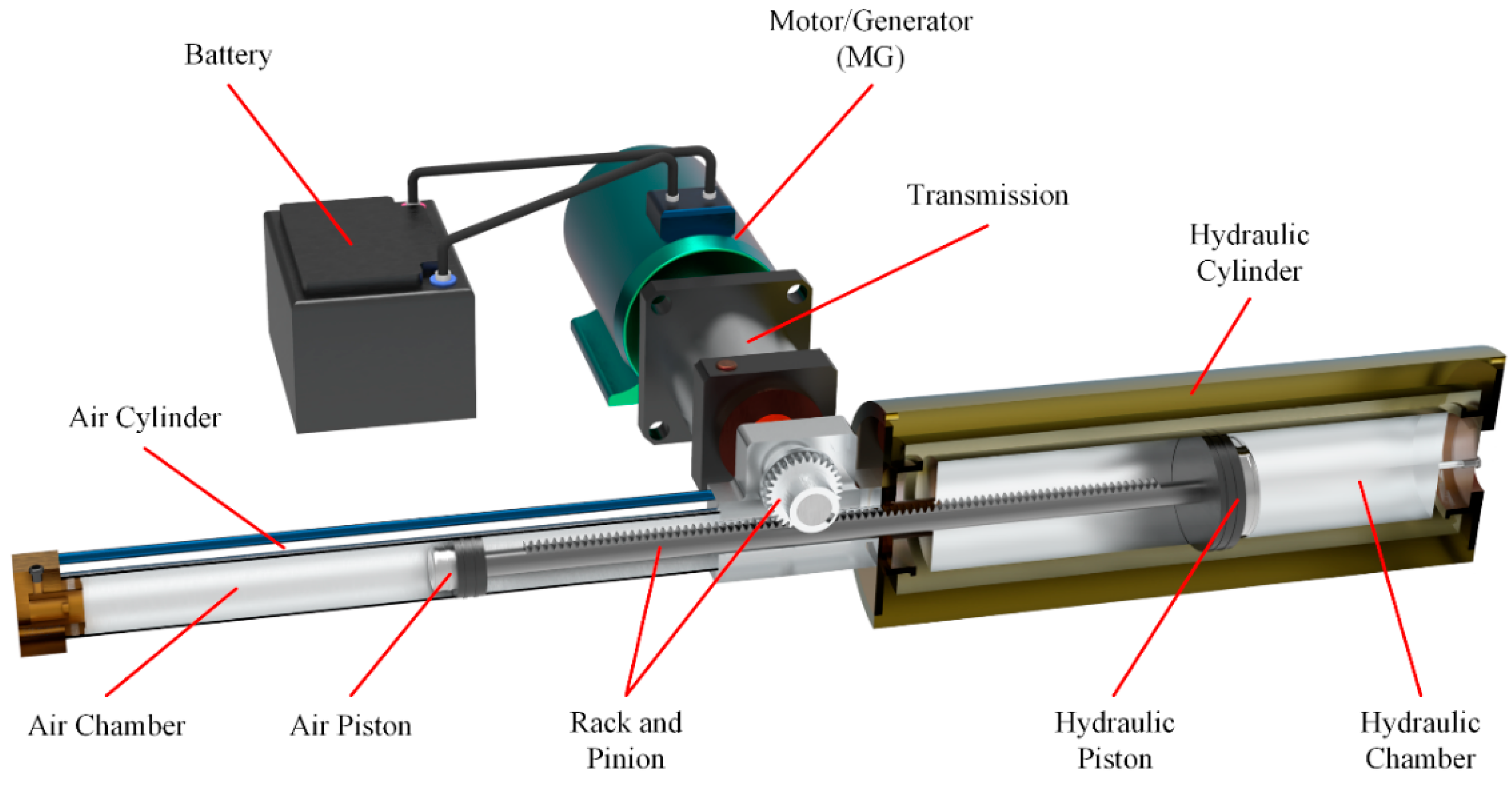
To address the existing issues, this paper proposes a novel HESC, as shown in Figure 1. The NHESC consists of three energy units and one conversion unit (including a rack and pinion). The three energy units comprise a hydraulic unit (consisting of a hydraulic chamber, hydraulic cylinder, and piston), an air unit (including an air chamber, air cylinder, and piston), and an electrical unit (featuring a battery, motor generator (MG), and transmission).

Figure 1.
Structure of the NHESC.
The hydraulic unit primarily manages the absorption and release of energy within the hydraulic system. The gas unit handles the storage and discharge of compressed air energy. The electrical unit oversees the storage and distribution of electrical energy. Acting as the energy exchange interface, the conversion unit facilitates the transformation among hydraulic, pneumatic, and electrical energies.
2.2. Modeling
2.2.1. Hydraulic Unit
The expression of the hydraulic cylinder force balance equation is as follows:
where is the force exerted on the hydraulic piston, is the hydraulic chamber pressure, is the active area of the hydraulic chamber, is the viscous friction coefficient of the hydraulic chamber, is the hydraulic piston displacement, and is the hydraulic piston mass.
The flow continuity equation of the hydraulic cavity can also be obtained as follows:
where is the flow in and out of the hydraulic chamber, is the leakage coefficient of the hydraulic chamber, and Vh is the effective volume of the hydraulic chamber.
The input/output energy of the hydraulic chamber can be defined as follows:
where is the input/output power of the hydraulic chamber.
2.2.2. Air Unit
The perfect air state equation can be obtained as follows:
where is the pressure of the air chamber, is the volume of the air chamber, is the air mass in the air chamber, is the air constant, and is the air temperature of the air chamber.
where is the force exerted on the air piston, is the effective area of the air chamber, is the coefficient of viscous friction of the air chamber, is the displacement of the air piston, and is the mass of the air piston.
The stored energy of the air unit Ea can be expressed as follows:
where and are the volume of the air chamber in the initial and final states, respectively, is the pre-pressure of the air unit, and is the volume of the air chamber in the pre-pressure state.
2.2.3. Electrical Unit
For the brushless DC motor, the torque balance equation of a DC brushless motor can be expressed as follows:
where J is the moment of inertia of the load and the rotor, is the system speed, is the electromagnetic torque of the DC motor, and is the load torque.
The dynamic voltage of the DC motor can be expressed as follows:
where is the counter electromotive force, is the equivalent resistance value, i is the current, is the inductance, and is the mutual inductance.
The state of charge (SOC) for the battery can be expressed as follows:
where SOC0 is the initial value of SOC and . The ampere hour (Ah) capacity of the battery corresponds to the rate of change of current i. The energy supply of the battery can be expressed as follows:
where is the terminal voltage of the battery, depending on the current and SOC.
2.3. Working States
Common HESCs, such as hydro-pneumatic accumulators, typically operate in two states: energy absorption and energy release. In the absorption state, hydraulic energy is converted into storable forms (e.g., compressed gas energy or elastic potential energy). In the release state, stored energy is converted back into hydraulic energy.
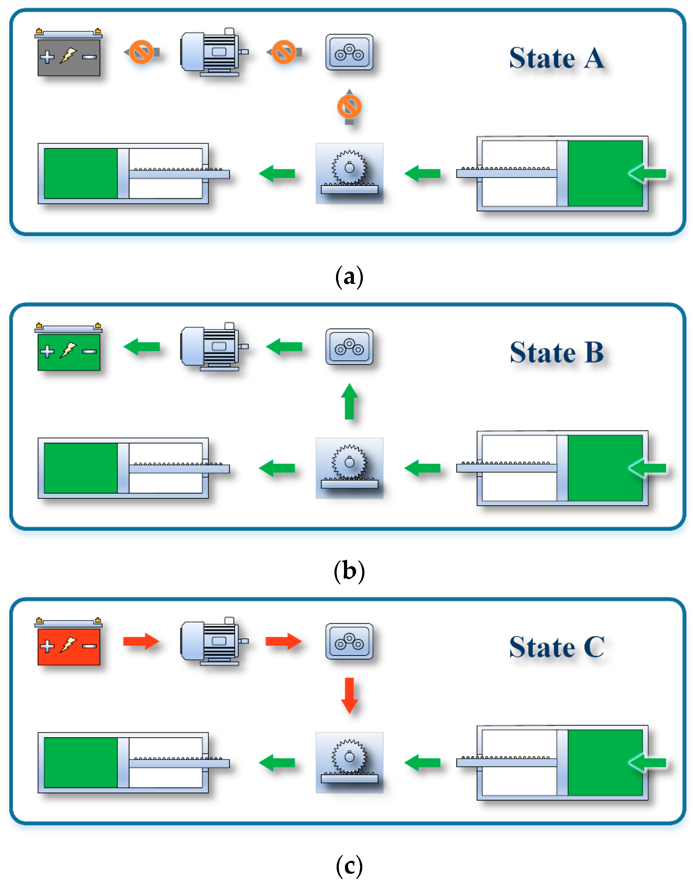
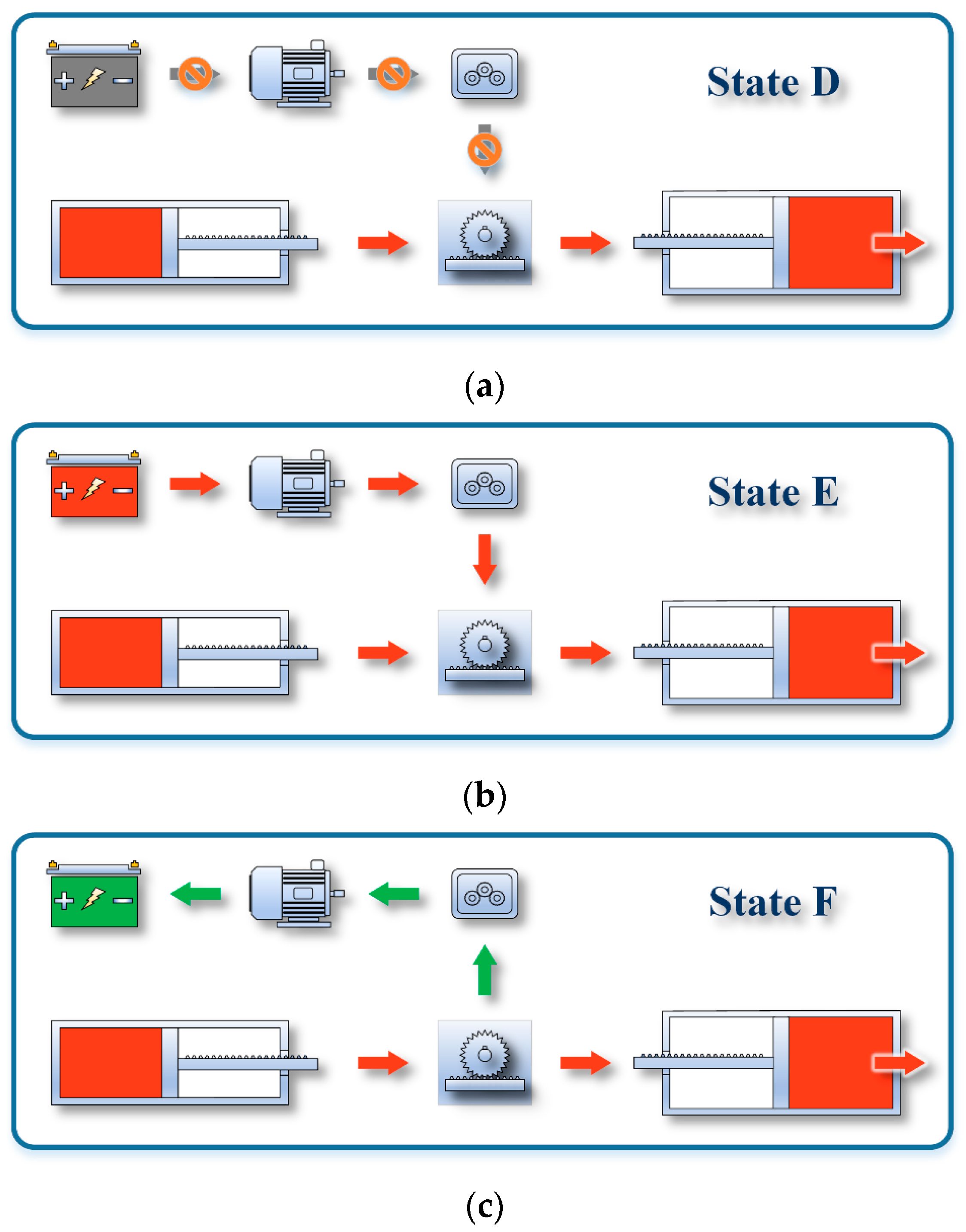
The NHESC studied in this paper becomes more complex due to the inclusion of an electrical unit and a conversion unit. To better analyze the energy exchange process, six working states are proposed. Given the complexity, an energy flow diagram is used to explain these states. In the first three states, the NHESC absorbs hydraulic energy from the external hydraulic circuit, as depicted in Figure 2a–c. In the last three states, the NHESC releases hydraulic energy into the external hydraulic circuit, as shown in Figure 3a–c. In Figure 2 and Figure 3, green arrows represent the energy absorbed by the corresponding energy unit, and red arrows represent the energy released by the same unit.
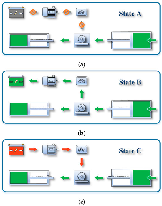
Figure 2.
Schematic of energy absorption states for the NHESC: (a) State A; (b) State B; (c) State C.
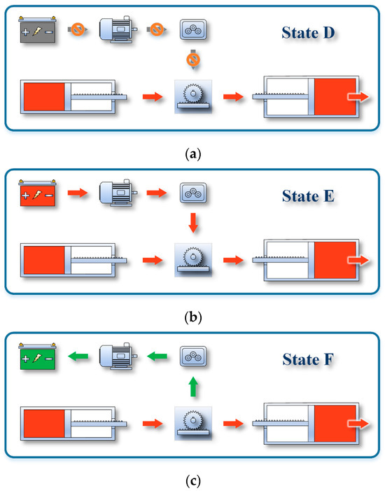
Figure 3.
Schematic of energy releasing states for NHESC: (a) State D; (b) State E; (c) State F.
In state A, the hydraulic unit absorbs energy from the external hydraulic circuit and transfers it to the air unit, as shown in Figure 2a, through energy form conversion. Additionally, the electrical unit is inactive in this state.
In state B, the energy absorbed by the hydraulic unit is transferred to both the air unit and the electrical unit, as illustrated in Figure 2b. During state B, the system simultaneously stores compressed air energy and electrical energy, utilizing the conversion unit for this purpose.
State C is a unique working state, as illustrated in Figure 2c. As the hydraulic unit absorbs energy and transfers it to the air unit, the electrical unit similarly transfers energy to the air unit.
For hydro-pneumatic accumulators, state D corresponds to state A, as shown in Figure 3a. In state D, the compressed air energy in the air unit is converted into hydraulic energy by the hydraulic unit, which is then released to the external hydraulic circuit. The electrical unit remains inactive in this state.
State E is an energy release state corresponding to state B, as illustrated in Figure 3b. In this state, the air unit and the electrical unit operate simultaneously to convert compressed air and electrical energy into hydraulic energy, which is then discharged into the external hydraulic circuit.
State F is a unique working state, with the energy flow direction opposite to that of state C. In this state, some of the compressed air energy in the air unit is converted into electrical energy and stored in the battery. Conversely, the remainder is transformed into hydraulic energy by the hydraulic unit and released into the external hydraulic circuit.
The conversion of specific energy forms across the six states is summarized in Table 1.

Table 1.
Working state descriptions of NHESC.
3. Determination Strategies of Working States
Since the NHESC has six working states, determining the appropriate state is crucial. Based on energy absorption and release, corresponding determination strategies are developed. The working state of the NHESC is defined by key internal parameters, including the hydraulic unit pressure , air unit pressure , and the battery’s SOC in the electrical unit.
3.1. Energy Absorption Determination Strategy
Based on the above, the energy absorption strategy of the NHESC must be determined by its key internal parameters, as illustrated in Figure 4. The steps to determine the energy absorption strategy are as follows:
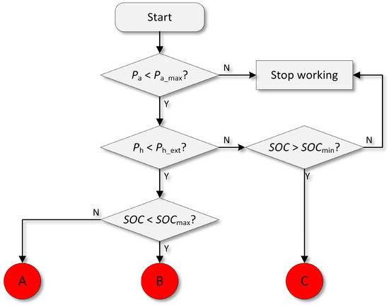
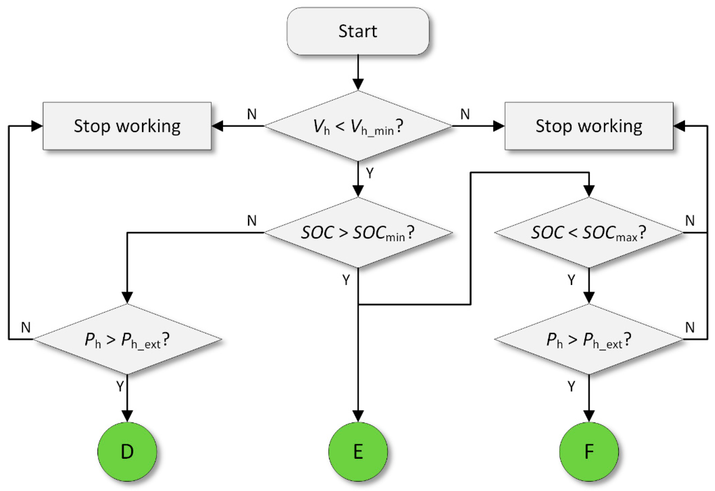
Figure 4.
Flow chart of energy absorption discrimination strategy.
- ①
- Consider whether the air unit pressure exceeds its maximum rated pressure ; If the exceeds , then the NHESC can only stop working; otherwise, it will enter ②.
- ②
- After determining whether the air unit can absorb energy, it is necessary to determine whether the external hydraulic circuit pressure is greater than the hydraulic unit pressure , and if so, then it can enter ③; otherwise, it will enter ④.
- ③
- The value of SOC determines whether the electrical unit can absorb energy normally, and if the SOC is lower than SOCmax, then it enters state B; otherwise, it enters state A.
- ④
- If the SOC is greater than the SOCmin, then state C is entered; otherwise, the NHESC stops working.
3.2. Energy Release Determination Strategy
Similar to the energy absorption decision strategy, the energy release decision strategy also necessitates the collection of relevant key parameters, as shown in Figure 5. The steps for determining energy release are as follows:

Figure 5.
Flow chart of energy release discrimination strategy.
- ①
- First, it is necessary to determine whether the volume of the hydraulic unit is sufficient for energy release. If the hydraulic unit volume exceeds its minimum working volume , then it can enter ②; otherwise, the NHESC stops working.
- ②
- When the SOC is greater than SOCmin, the NHESC can directly enter state E or ③; otherwise, it can proceed to ④.
- ③
- If the SOC is less than SOCmax and the hydraulic unit pressure is greater than the pressure of the external hydraulic circuit, then the NHESC enters state F.
- ④
- If the SOC is greater than SOCmax and the hydraulic unit pressure is greater than the external hydraulic circuit pressure , then the NHESC enters state D.
4. Simulation and Experiment
4.1. Experimental Platform
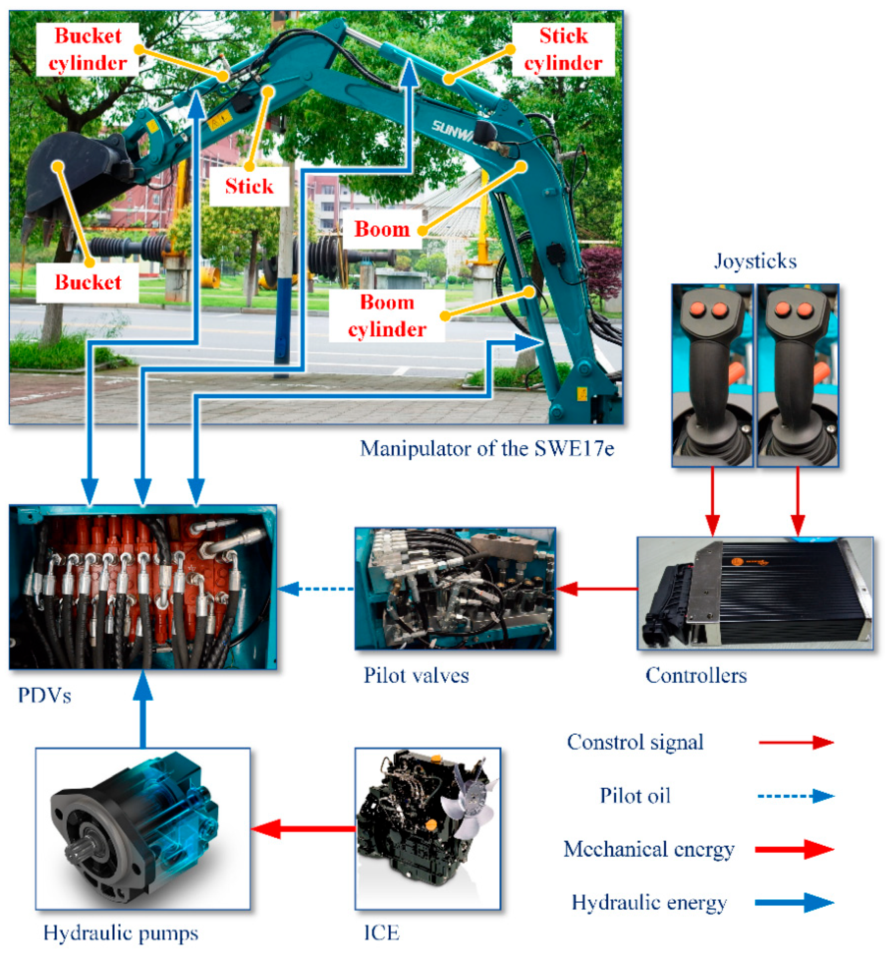
A boom PER system will be established using the 1.7-ton mini-excavator as the experimental platform. This system will be used to study the working process and energy regeneration efficiency of NHESCs. The HTS schematic of the 1.7-ton mini-excavator is shown in Figure 6.

Figure 6.
Schematic of HTS of 1.7-ton mini-excavator.
Figure 6 illustrates the 1.7-ton hydraulic excavator, comprising three primary components: the bucket, stick, and boom. Their respective cylinders facilitate movement among these parts: the bucket cylinder, stick cylinder, and boom cylinder. Coordinated actions result from the synchronization of these cylinders. The operation of these cylinders is controlled by proportional directional valves (PDVs). Pumps powered by an internal combustion engine (ICE) generate pressurized oil. The joystick signal is processed by the controller and sent to the pilot valve, which regulates the pilot oil and actuates the PDVs. Component parameters for a 1.7-ton mini-excavator are outlined in Table 2.
Table 2.
Specifications and parameters of 1.7-ton mini-excavator.
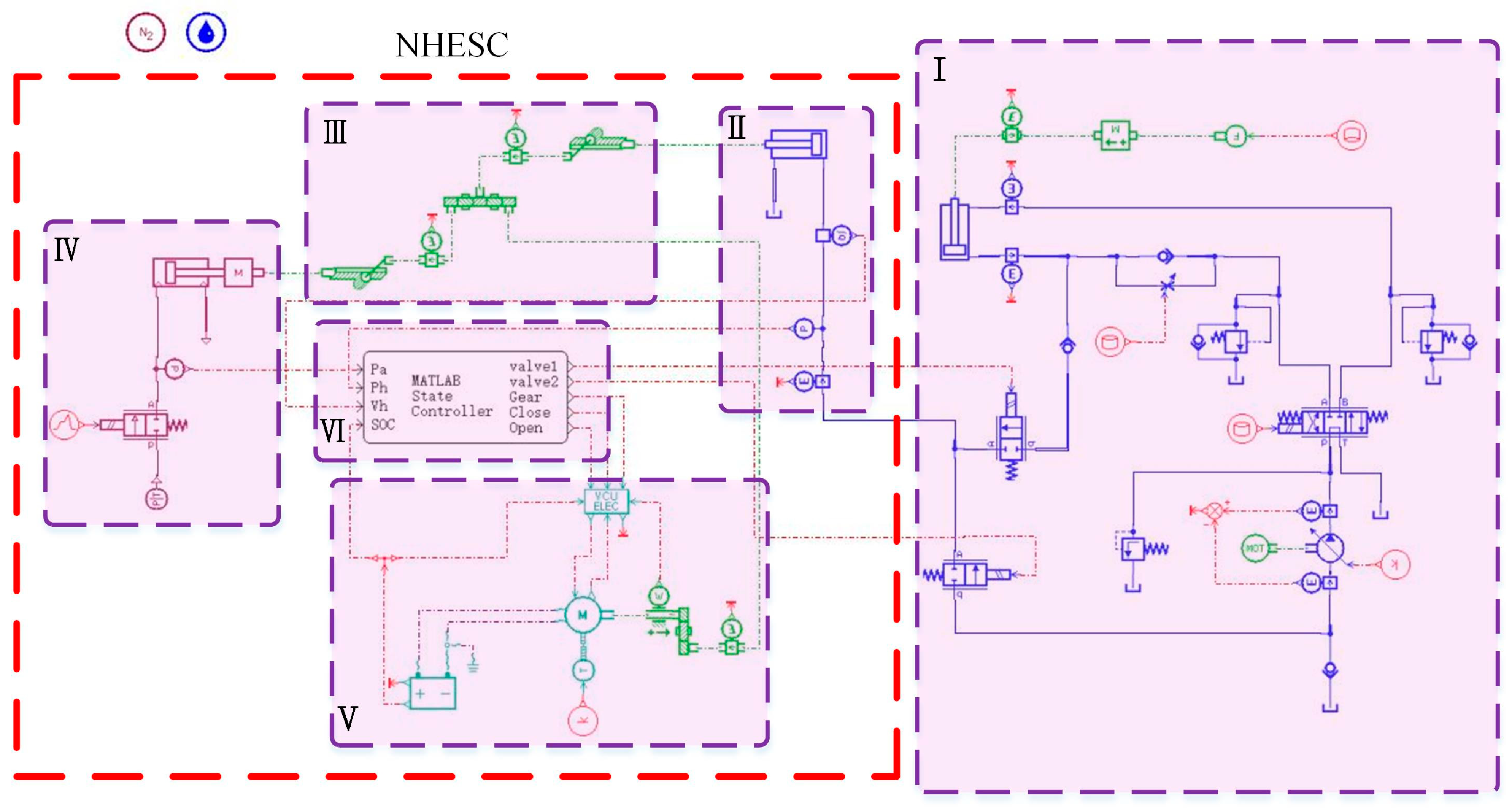
Based on the hydraulic circuit and oil flow in Figure 7, simulation models for the NHESC and boom PER system have been developed in AMESim, as shown in Figure 8. In Figure 8, part I illustrates the boom hydraulic circuit that drives the boom cylinder. At the same time, the NHESC comprises the hydraulic unit (II), transfer unit (III), air unit (IV), electrical unit (V), and control unit (VI). The NHESC is indicated by a red dotted line, whereas the other components are encased within a purple dotted box in Figure 8. The control unit (VI) implements the determination strategies proposed in Section 3. For comparison, simulation models are also established for both the no-accumulator mode and the accumulator mode (equipped with a traditional hydro-pneumatic accumulator).

Figure 7.
Boom PER system using NHESC and oil flow: (a) Energy recovery; (b) Energy reuse.
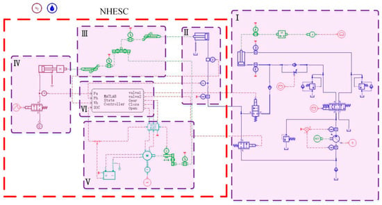
Figure 8.
Simulation model under NHESC mode: I. Boom hydraulic circuit, II. Hydraulic unit, III. Conversion unit, IV. Air unit, V. Electrical unit, VI. Control unit.
4.2. Simulation Model
Based on the boom’s frequent movement and the operational characteristics of the NHESC, a hydraulic circuit for the boom PER system was designed, as shown in Figure 7. Figure 7a illustrates the oil flow (green arrows) for energy recovery, while Figure 7b depicts the oil flow (red arrows) for energy reuse. Since the pressurized oil carries energy, Figure 7 can also be interpreted as the energy flow diagram for the boom PER system.
The primary hydraulic component parameters for the three simulation models based on the 1.7-ton mini-excavator are outlined in Table 3. The essential parameters of the NHESC are listed in Table 4.
Table 3.
Main parameters of hydraulic components.
Table 4.
Main parameters of the NHESC.
4.3. Experimental Verification
This study uses the boom hydraulic circuit to gather operational pressure data, which is then converted into force parameters and applied to the boom cylinder in the Figure 8 simulation model for experimental validation. Given the experimental constraints, the verification method adopted is essentially a combination of physical testing and simulation.
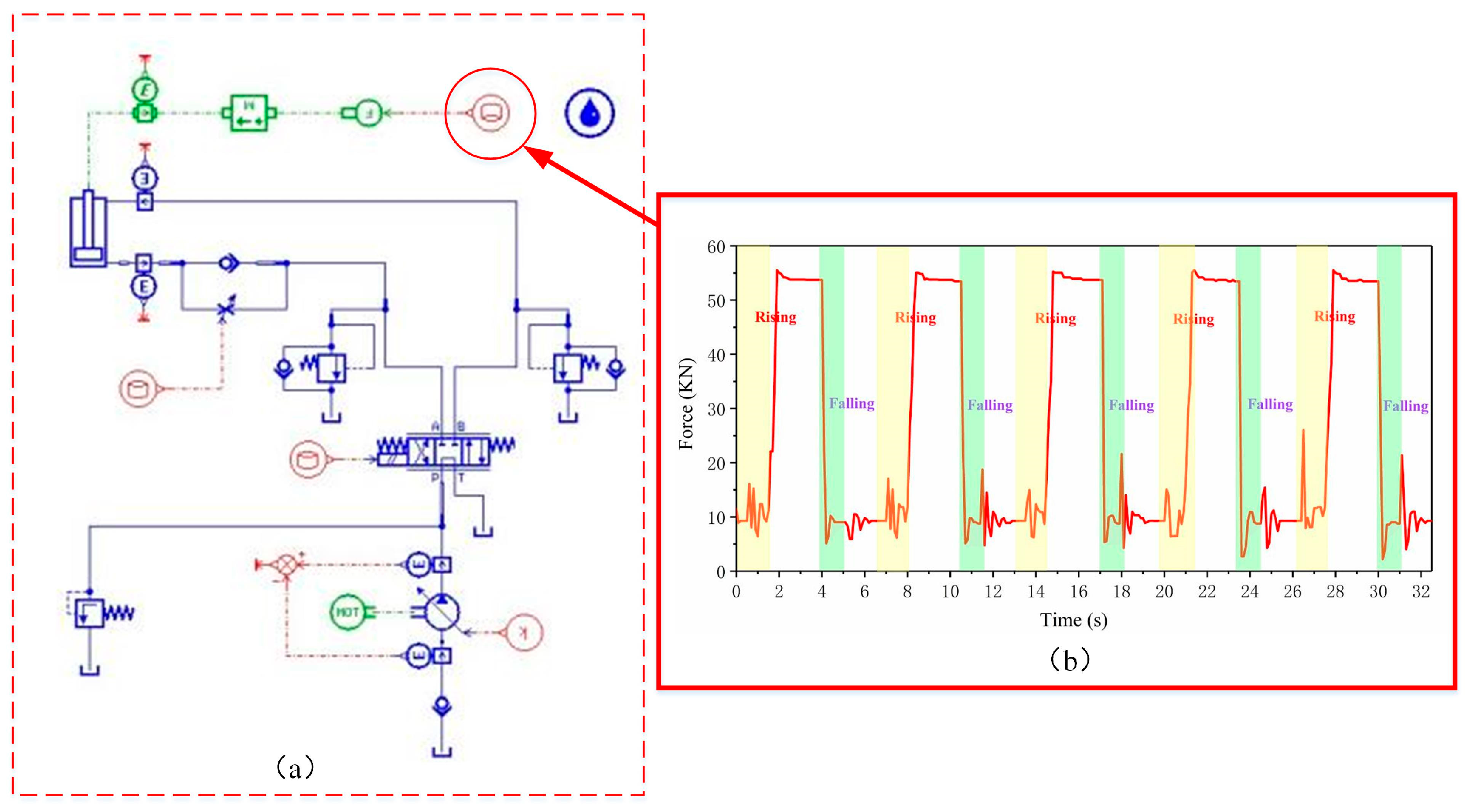
Figure 9 illustrates the measurement system used to collect data on boom operation. Three pressure sensors measure the pressure in the rodless chamber (P1), the rod chamber (P2), and the hydraulic pump (P3). Additionally, the speed signal (ω) of the ICE is recorded. Data from these sensors are gathered by Controllers #1 and #2, transmitted via the Controller Area Network (CANBus), and eventually sent to the data acquisition platform through a protocol converter and an industrial router. By utilizing CANBus, TCP/IP, and Wi-Fi, the system ensures an efficient data acquisition process, as shown in Table 5.
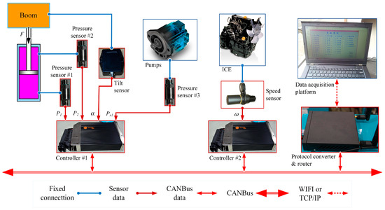
Figure 9.
Schematic diagram of the measurement system.
Table 5.
Component specifications of the measurement system.
To ensure standardization, the research test will be organized as follows (Figure 10):
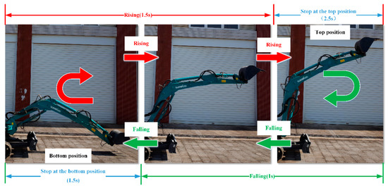
Figure 10.
Schematic diagram of a test cycle.
- (1)
- A no-load boom movement cycle consists of: Bottom (1.5 s), Rising (1.5 s), Stop at the top (2.5 s), and Falling (1.0 s);
- (2)
- Displacement of the piston rod of the boom cylinder: 0.32 m (bottom) and 0.45 m (top).
From this, a no-load cycle takes 6.5 s, as illustrated in Figure 10. Five consecutive cycles are performed in a test cycle, resulting in a total time of 32.5 s.
To validate the simulation model using collected data, the boom cylinder force was calculated from the recorded pressure data of both the rodless and rod chambers and applied to the no-accumulator mode simulation model (Figure 11). The rod force of the boom cylinder is shown in Figure 11b, while the red circle in Figure 11a highlights where the force data are integrated into the simulation. The PDV control signal in the simulation model was adjusted according to the boom motion test cycle to ensure consistency with actual operation. This setup provides a theoretical basis for further analysis of the accumulator mode and NHESC mode.
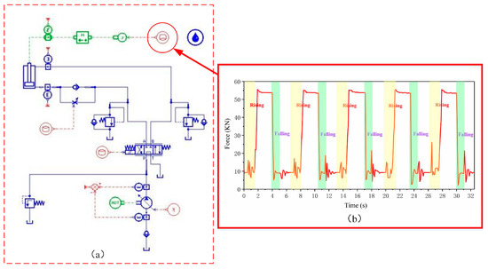
Figure 11.
Simulation model with a test cycle: (a) Simulation model of no-accumulator mode; (b) Rod force.
As seen in Figure 10, the boom starts to move from the bottom position. First, the boom is controlled to rise until it reaches its top position. This rising stage takes 1.5 s. After the boom reaches the top position, it remains there for 2.5 s. Then, the boom descends until it reaches the specified bottom position. This falling stage takes 1 s, and finally, the boom stays at the bottom for 1.5 s. This marks the end of the boom’s working cycle. The highest boom position is 0.45 m, while the lowest is 0.32 m. To minimize vibration effects during the transition between rising and falling, a 1.5 s interval is maintained when the boom reaches the bottom of each cycle. Additionally, sensor data transmission delays and control signal delays are considered to adjust the test cycle timing, ensuring effective alignment with the simulation model.
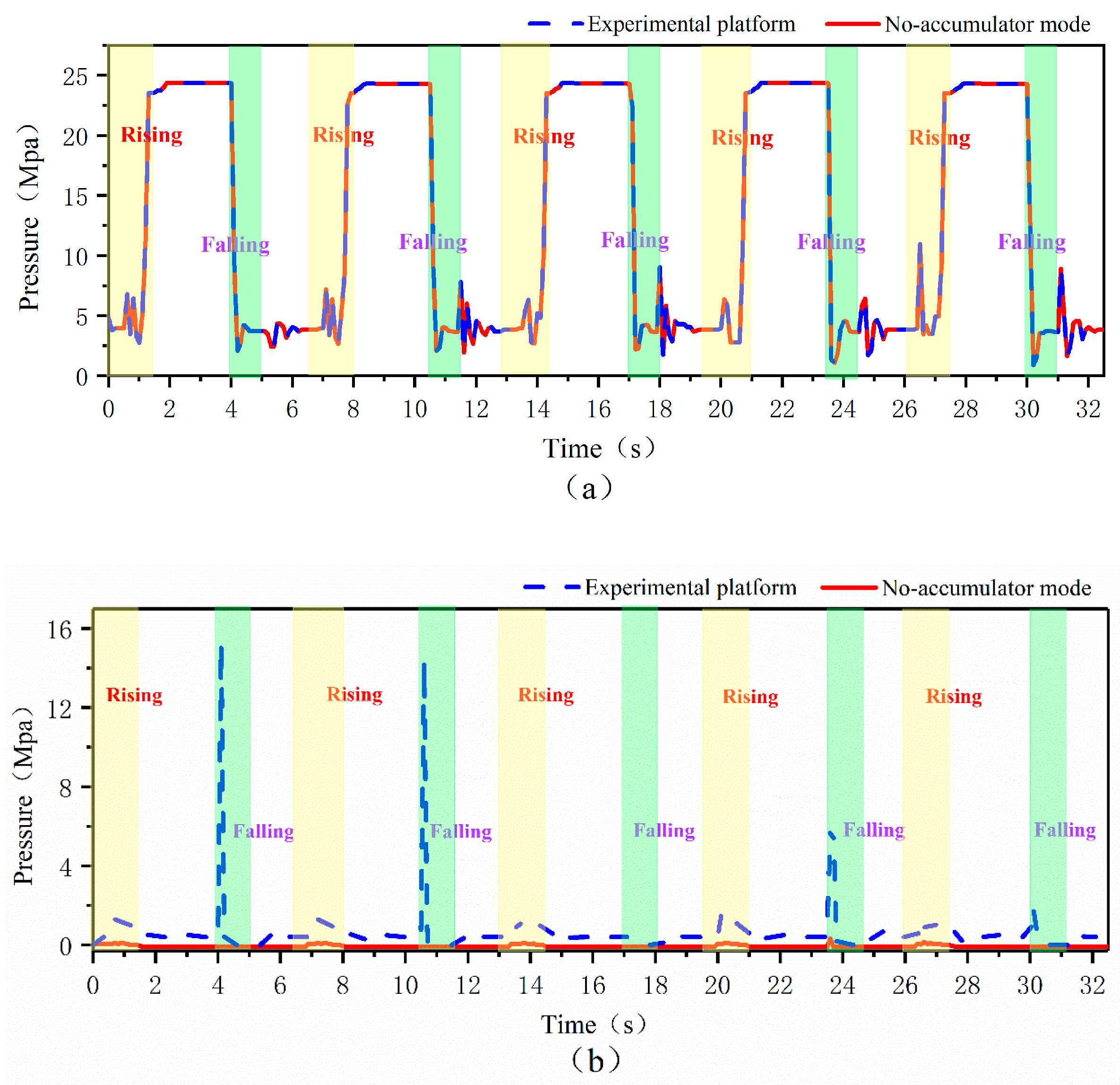
By comparing the pressures in the rod and rodless chambers of the boom hydraulic cylinder, the test data closely align with the simulation results for the no-accumulator mode, confirming the simulation’s accuracy, as shown in Figure 12. Due to limitations in experimental equipment and conditions, validation through testing is only possible for the no-accumulator simulation model. In contrast, experimental verification of the accumulator and NHESC modes is not feasible. Consequently, a corresponding simulation model based on the no-accumulator mode was developed, and relevant data were compared through simulations to verify the energy-saving effect of the proposed NHESC.
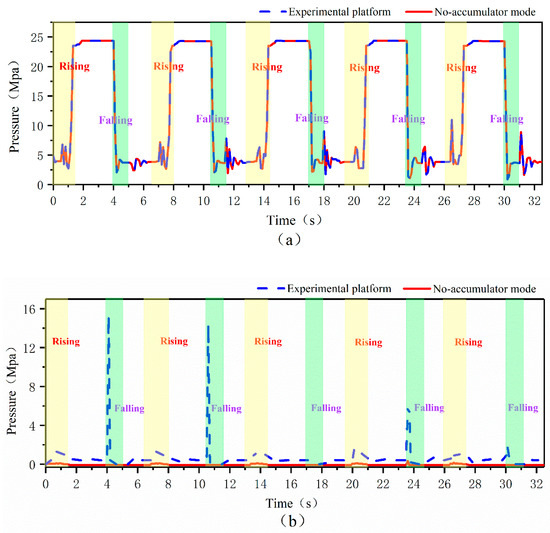
Figure 12.
Comparison of boom cylinder chamber pressures between the no-accumulator mode simulation model and the experimental platform: (a) Pressure in the rodless chamber; (b) Pressure in the rod chamber.
It can be seen from Section 3 that the NHESC can choose working states for energy recovery and reuse. When the NHESC recovers energy, it can select three working states: A, B, and C. For energy reuse, it can choose three working states: D, E, and F. Considering the relatively complex working conditions of the NHESC mode, only four working state pairs utilized by the NHESC throughout the entire boom test cycle are analyzed: A-D, B-D, B-E, and B-F. The working principles of the four working state pairs of the NHESC are presented in Table 6.
Table 6.
Four working states of NHESC and their working principles.
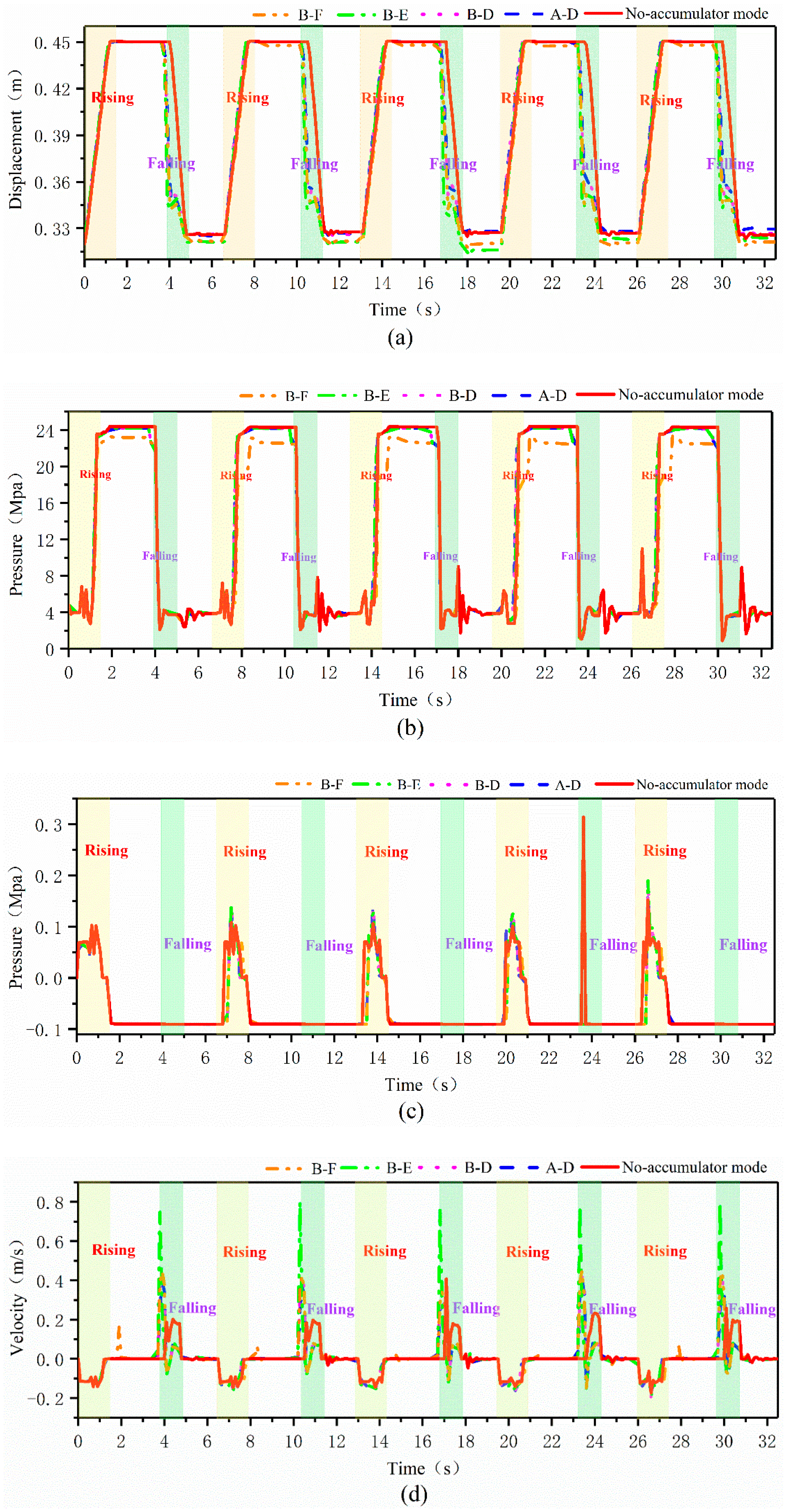
To verify that the boom can still function normally when the NHESC adopts these four working states, the parameters of the no-accumulator mode are extracted for comparison and analysis with the four paired working states of the NHESC mode, as illustrated in Figure 13.

Figure 13.
Comparison of boom cylinder variables between the no-accumulator mode and the four working states of NHESC: (a) Piston displacement; (b) Rodless chamber pressures; (c) Rod chamber pressures; (d) Piston velocity.
Figure 13a shows the displacement comparison of the boom piston, with a range from 0.32 m (bottom) to 0.45 m (top). Energy recovery during boom descent in working state pairs A-D, B-D, B-E, and B-F causes displacement fluctuations. Figure 13b,c show pressure curves for the rodless and rod chambers of the boom cylinder. In NHESC mode B-F, the rodless chamber pressure fluctuates. In contrast, the rod chamber pressure in the no-accumulator mode exhibits significant fluctuations in the fourth period due to sensor error. The pressures in NHESC states A-D, B-D, B-E, and B-F are similar to those in no-accumulator mode I. Figure 13d shows the curve of piston rod speed change. During the entire working cycle, in the NHESC working state pairs A-D, B-D, B-E, B-F, and no-accumulator mode I, the piston rod speed remains essentially constant when the boom is rising. When the boom falls, the four working state pairs in the NHESC mode exhibit fluctuations compared to the non-accumulator mode. Among these, B-E experiences the most severe fluctuation in rotation speed, with the piston speed reaching as high as 0.8 m/s. Through the above comparison, the working state pairs A-D, B-D, B-E, and B-F can carry out energy recovery and reuse during the boom’s falling and rising phases, and the NHESC can be utilized in the boom PER system.
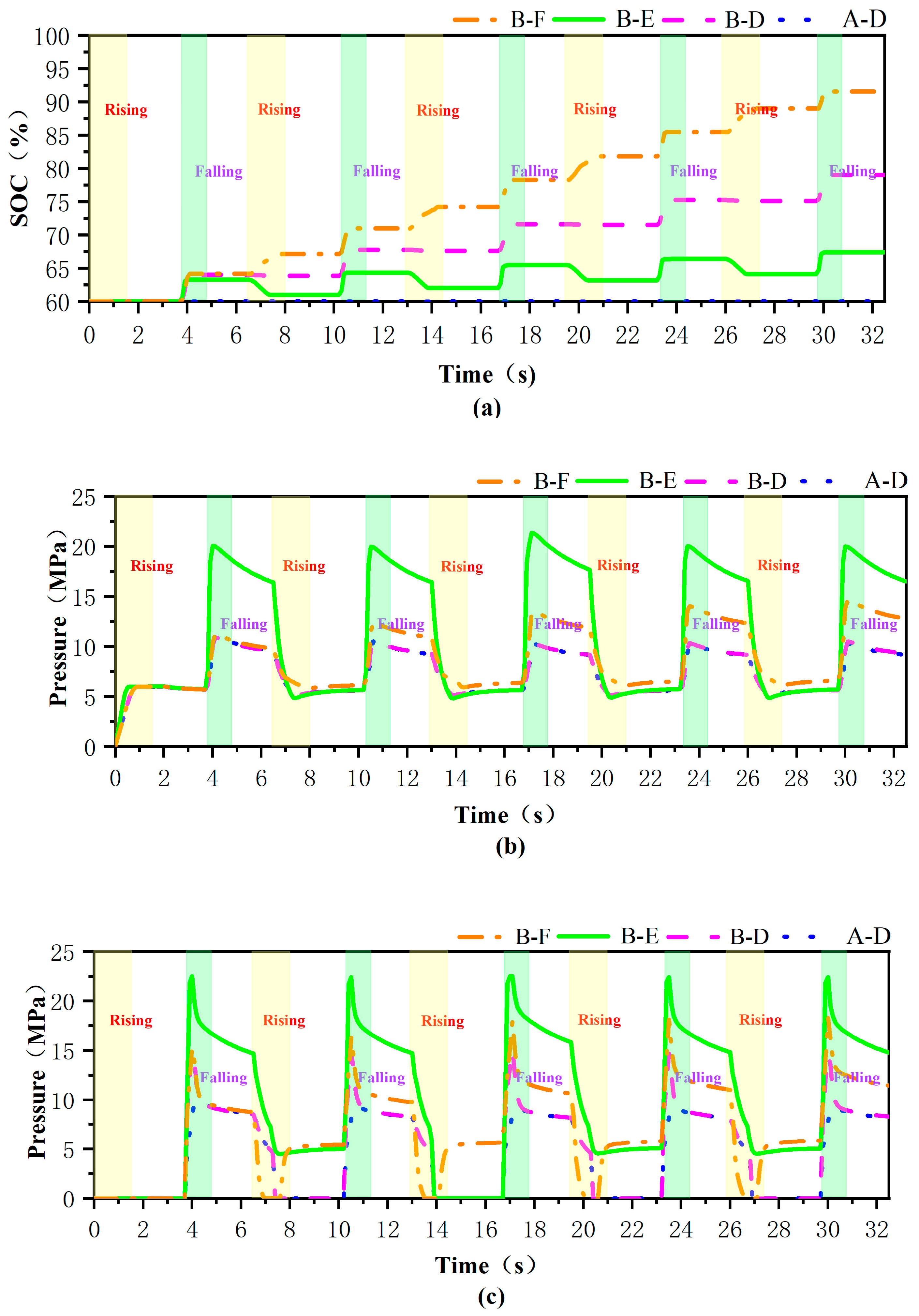
The initial SOC of the battery is set to 60%. Figure 14a illustrates the variation of SOC throughout the entire cycle in four different modes. The SOCs for B-E, B-D, and B-F reached 67.39%, 79.01%, and 91.58%, respectively. The initial pressure of the air unit is set to 5 MPa. Figure 14b depicts the pressure variation of the air unit throughout the entire cycle across the four different modes. The maximum pressures for A-D, B-D, B-F, and B-E were 10.4 MPa, 10.5 MPa, 14.5 MPa, and 21.2 MPa, respectively. Figure 14c illustrates the pressure variation of the hydraulic unit throughout the entire cycle under four different operating modes. Additionally, the maximum pressures for A-D, B-D, B-F, and B-E were 9.9 MPa, 14.9 MPa, 18.5 MPa, and 22.5 MPa, respectively.
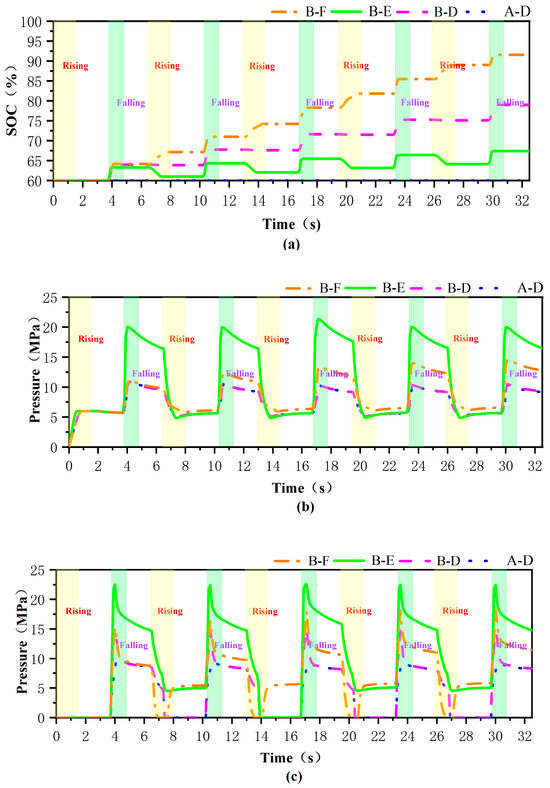
Figure 14.
Comparison of the NHESC’s four working states: (a) SOCs of battery; (b) Pressures of air unit; (c) Pressures of hydraulic unit.
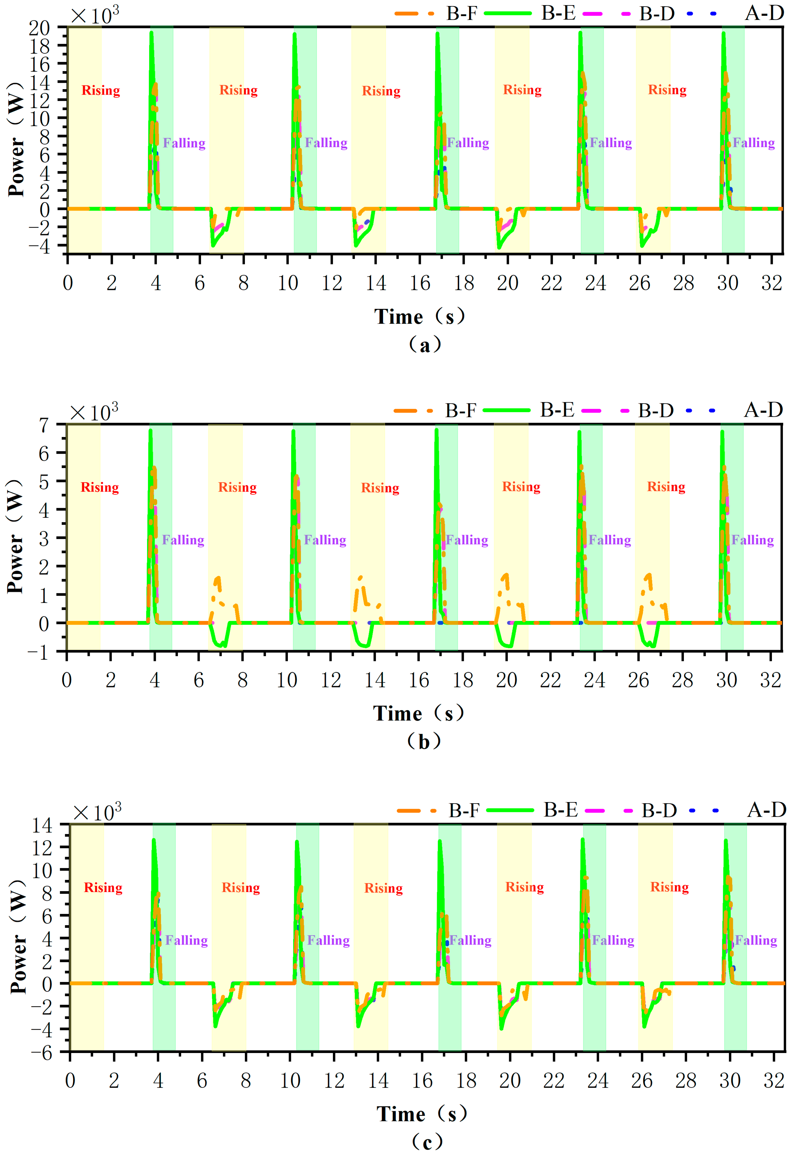
Figure 15a illustrates the power variation curve of the hydraulic cylinder within the hydraulic unit under four working state pairs of the NHESC mode throughout the entire working cycle. Figure 14 indicates that when the boom falls, the positive power change curve for each working state is largely similar, with the positive power change for B-E being the most significant, reaching approximately 19.4 KW. Conversely, when the boom rises, the most notable negative power change is also observed in working state B-E, which can attain approximately 4.3 KW. Figure 15b,c respectively display the power dynamics of the battery and air cylinder, clearly demonstrating the power distribution behavior of the NHESC.
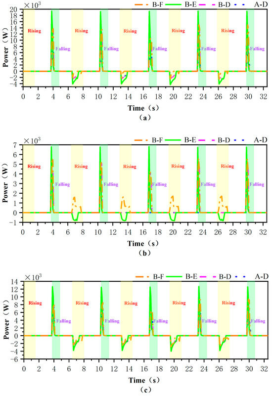
Figure 15.
Power comparison between the NHESC’s four working states: (a) Power variation curve of hydraulic cylinder; (b) Power variation curve of battery; (c) Power variation curve of air cylinder.
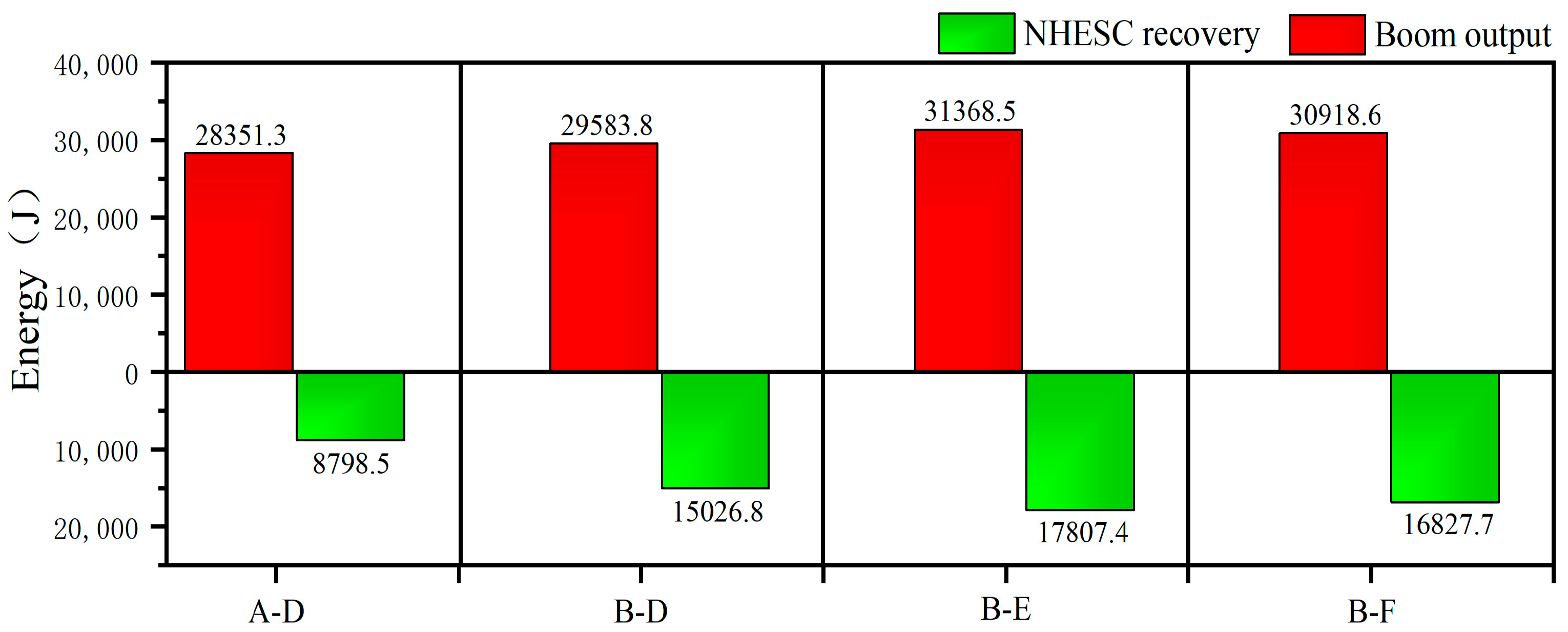
Figure 16 illustrates the energy generated when the boom descends throughout the working cycle and the energy recovered from the boom in the four working states of the NHESC. The output energy of the boom in working state A-D is 28,351.3 J over the entire working cycle, allowing for a recovery of 8798.5 J. In working state B-D, the boom generates an output energy of 29,583.8 J throughout working as the whole cycle, which enables a recovery of 15,026.8 J. During the working cycle in working state B-E, the boom produces an output energy of 31,368.5 J, permitting a recovery of 17,807.4 J. Lastly, the output energy of the boom in working state B-F during the working cycle is 30,918.6 J, allowing for a recovery of 16,827.7 J.
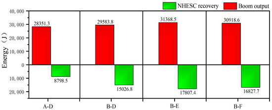
Figure 16.
Four working state transitions in NHESC recovery energy.
Through the analysis of the four working states of NHESC, the best energy-saving effect is observed in working state B-E.
5. Energy Efficiency Analysis
In Section 4, we discussed the energy efficiency of four state transitions under NHESC, with B-E representing the most efficient transition mode. To enhance the analysis, we selected the boom PER system developed by B-E in the NHESC for comparison with the boom PER system produced by hydraulic accumulators, demonstrating that NHESCs offer better energy efficiency than hydraulic accumulators.
5.1. Comparison Between NHESC and Hydraulic Accumulator
In the previous section, an analysis of the four working states in the NHESC mode concluded that optimal energy-saving performance is achieved by the working state pair B-E. To verify the energy-saving effect of the NHESC, a comparison is presented between the NHESC mode working states B-E and the accumulator mode.
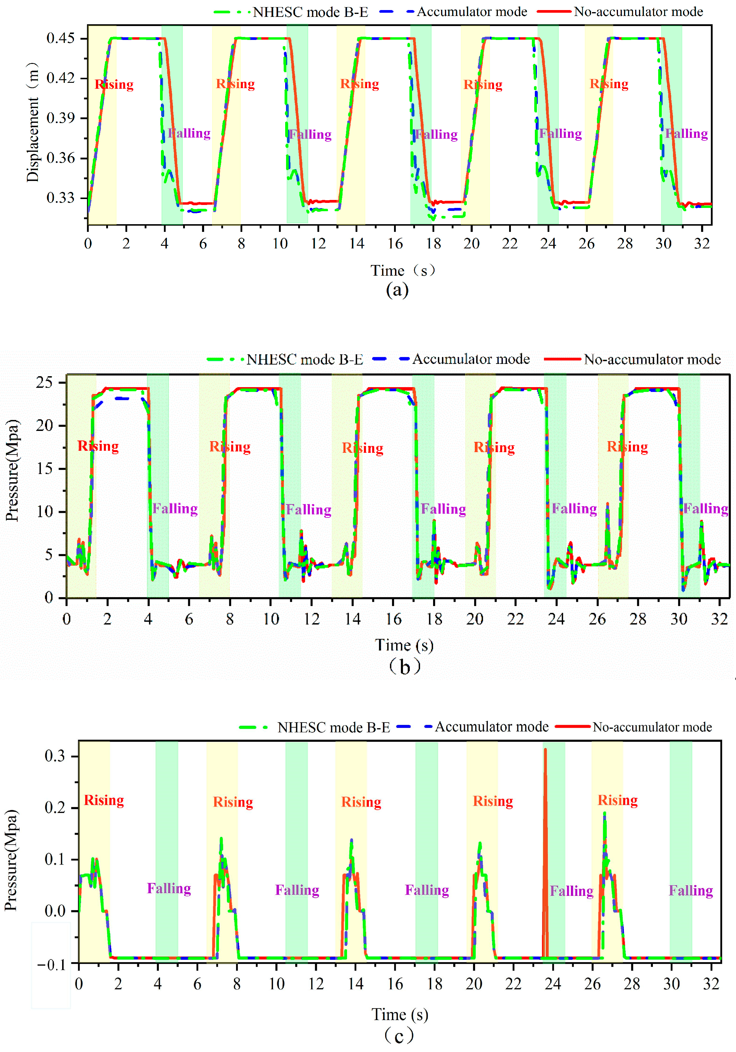
Before verifying the recovery and reuse energy efficiency of the NHESC mode and accumulator mode, it is crucial to establish whether the boom can maintain normal working conditions in both modes throughout the entire working cycle. Therefore, comparing and analyzing the data from these two modes alongside the data from the boom hydraulic cylinder in no-accumulator mode is essential. Figure 17 presents a comparison curve of the NHESC mode working state B-E, the accumulator mode, and the no-accumulator mode for the boom hydraulic cylinder. From Figure 17a, it is evident that since the working state pair B-E and the accumulator mode depend on recovering energy when the boom is lowered, the curve drops more sharply and fluctuates somewhat compared to the no-accumulator mode. However, when the boom rises, the displacement curves of all three modes are mainly identical.
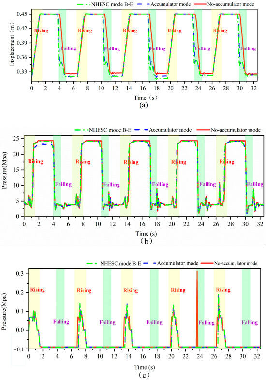
Figure 17.
Data analysis of NHESC mode B-E, accumulator mode, and no-accumulator mode of the boom cylinder: (a) Displacement, (b) Rodless chamber pressures, (c) Rod chamber pressures.
Throughout the entire working cycle, the pressure change curves for both the rodless and rod chambers across all three modes are similar. Only during the first cycle does the accumulator mode show a slightly lower maximum pressure in the boom rodless chamber compared to the other two modes, as illustrated in Figure 17b,c.
According to the data analysis, throughout the entire cycle of the boom’s rise and fall, the energy storage elements in both NHESC and accumulator modes support energy recovery and reuse while having minimal impact on the normal operation of the boom. Consequently, the following analysis focuses on the energy regeneration efficiency of the NHESC and accumulator modes.
5.2. Energy Regeneration Efficiency Analysis
5.2.1. Definitions
To assess energy efficiency, three definitions of energy efficiency are introduced as follows [5]:
The recovery efficiency can be expressed as
where ERC is the recovery energy by the accumulator and EBF is the boom potential energy.
The reuse efficiency can be expressed as
where EBR is the energy from the ERC to lift the boom.
Finally, the regeneration efficiency can be expressed as
5.2.2. Recovery Efficiency
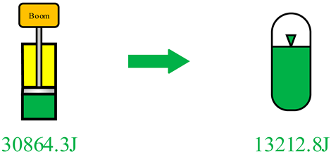
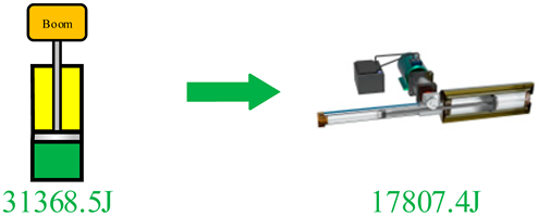
Table 7 shows that the boom hydraulic cylinder in the accumulator mode released a total of 30,864.3 J of energy during the entire falling working cycle, while the accumulator recovered 13,212.8 J. The energy recovery efficiency for the accumulator mode is calculated to be 42.81%. In the NHESC mode B-E, the boom hydraulic cylinder released a total of 31,368.5 J of energy during the entire falling working cycle, and the NHESC recovered 17,807.4 J. The recovery efficiency of the NHESC mode B-E is calculated to be 56.77%. The recovery efficiency of NHESCs exceeds that of accumulators.
Table 7.
Comparison of recovery efficiency between NHESC mode B-E and accumulator mode.
5.2.3. Reuse Efficiency
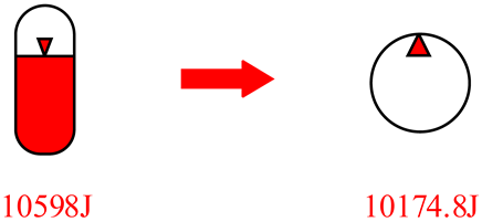
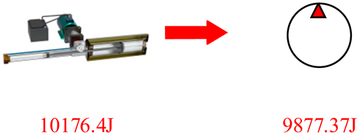
In Table 8, the hydraulic accumulator in accumulator mode releases 10,598 J of energy to assist the hydraulic pump during the boom rise cycle, while the pump consumes 10,174.8 J. The reuse efficiency of accumulator mode stands at 96.01%. In the NHESC mode B-E, the NHESC releases 10,176.4 J of energy, and the hydraulic pump uses 9877.37 J, leading to a reuse efficiency of 97.06%. Therefore, the NHESC mode B-E surpasses the accumulator in reuse efficiency.
Table 8.
Comparison of reuse efficiency between NHESC mode B-E and accumulator mode.
5.2.4. Regeneration Efficiency
Recovery efficiency and reuse efficiency in the NHESC mode B-E and accumulator mode allow for the calculation of regeneration efficiencies, as shown in Table 9. The regeneration efficiencies for accumulator mode and the NHESC mode B-E are 41.1% and 55.1%, respectively, indicating that NHESCs outperform accumulators in regeneration efficiency.
Table 9.
Comparison of regeneration efficiency between NHESC mode B-E and hydraulic accumulator mode.
5.3. Energy Loss
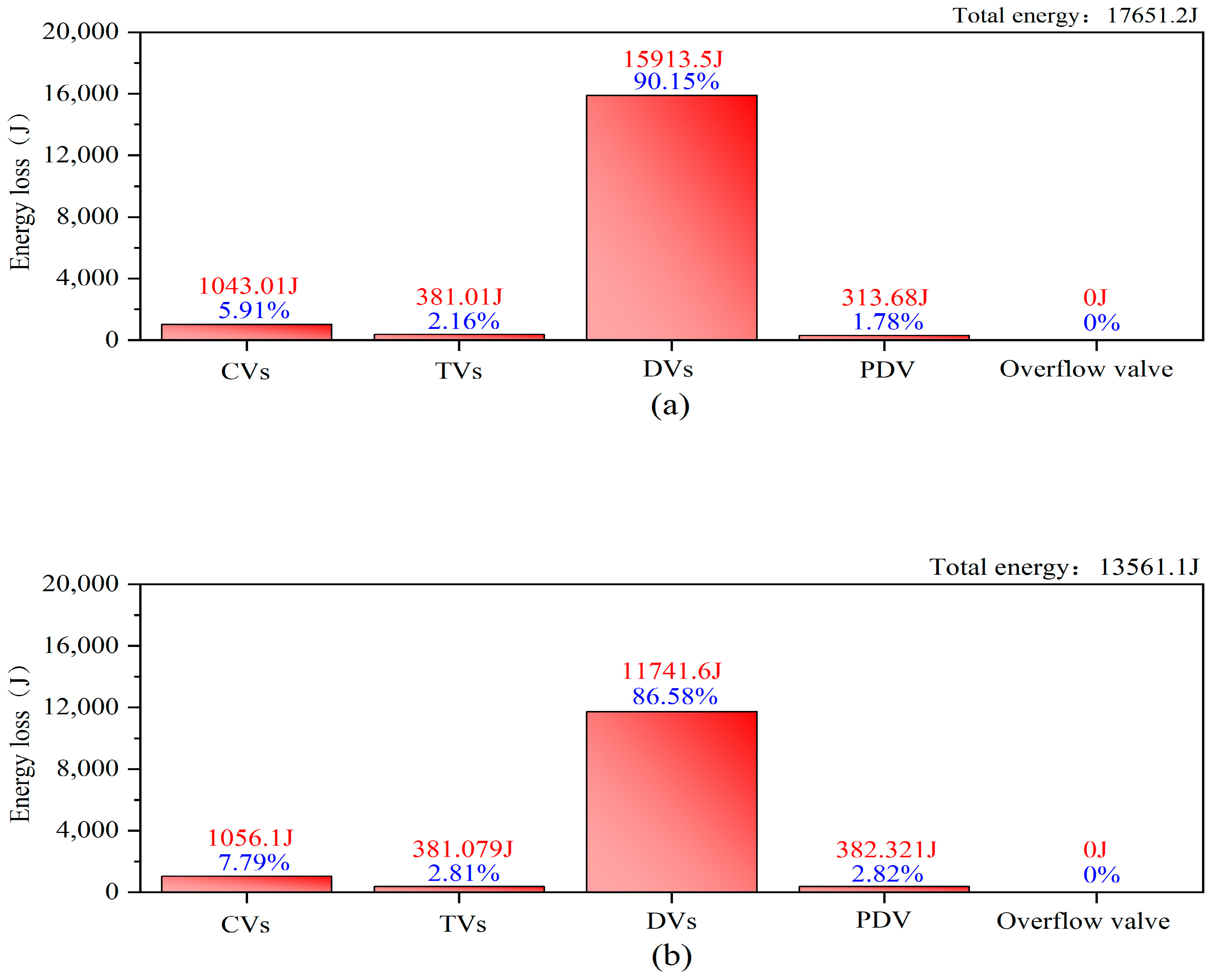
The preceding content analyzed power, energy, and efficiency, but the unrecovered energy loss during boom falling remains unclear. To assess NHESC and accumulator energy losses, this section examines hydraulic component losses, categorizing them into check valves (CVs), throttle valves (TVs), directional valves (DVs), proportional directional valves (PDVs), and overflow valves (OVs). Sensors were installed in NHESC mode B-E and accumulator mode simulations to measure each component’s energy consumption, as shown in Figure 18a,b.
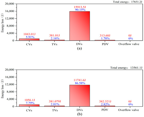
Figure 18.
Energy loss of boom fall: (a) accumulator mode energy loss; (b) NHESC mode B-E energy loss.
Based on Figure 18a,b sensor data on individual component energy consumption, and system efficiency comparisons, the following analysis is derived. During the boom fall phase of the entire working cycle, the accumulator mode lost a total of 17,651.2 J of energy, and the NHESC mode B-E lost a total of 13,561.1 In accumulator mode, the hydraulic component that consumes the most energy are the DVs, which consume 15,913.5 J of energy, followed by the CVs, which consume 1043.01 J; TVs, which consume 381.01 J; and the PDVs, which consume 313.68 J. In the NHESC mode B-E, the hydraulic component that consumes the most energy is also the directional valve, which consumes 11,741.6 J of energy in total, followed by the CVs, which consume 1056.1 J of energy; the PDVs, which consume 382.321 J of energy; and the TVs, which consume 381.079 J of energy. The OVs consume no energy in either mode. The energy loss of the accumulator is higher than that of the NHESC.
6. Conclusions and Prospects
To improve the energy efficiency of a hydraulic system, an NHESC was developed, accompanied by a state transition strategy, and subsequently verified through simulation and experimentation. The main research focus of this paper includes the following:
- (1)
- The structure of the NHESC was described, models of its main components were established, and six possible working states of the NHESC during the energy absorption and release processes were identified.
- (2)
- Strategies for determining entry into the six working states of the NHESC were provided.
- (3)
- The NHESC’s effectiveness was confirmed through a boom PER system simulation on a 1.7-ton mini-excavator. Experimental data identified B-E as the optimal working state pair.
- (4)
- The analysis of the boom PER system compared state pair B-E in both NHESC and accumulator modes, evaluating recovery, reuse, and regeneration efficiencies. The NHESC achieved a regeneration efficiency of 55.1%, exceeding the accumulator’s 41.1%.
The NHESC integrates compressed gas and electric energy storage, overcoming the limitations of passive operation and control in traditional hydraulic accumulators while enhancing energy regeneration efficiency. Further research is needed on the following aspects:
- (1)
- We intend to validate and optimize the threshold settings of the NHESC’s strategy for determining its working state under complex real-world conditions to ensure reliability and adaptability.
- (2)
- Developing comprehensive experimental platforms that can simulate complex operating conditions will enable a thorough evaluation of the NHESC’s performance across various scenarios.
- (3)
- Investigating advanced control strategies will facilitate precise regulation and optimization of the NHESC’s operating states, thereby improving the system’s dynamic response capabilities.
Future research will focus on these aspects, aiming further to enhance the NHESC’s performance and application value, contributing to improved energy efficiency and sustainable development in hydraulic systems.
Author Contributions
Conceptualization, X.H. and J.Y.; methodology, J.Y.; software, Y.Y. and J.Y.; validation, J.Y., X.H., Y.Z. and G.X.; formal analysis, J.Y.; investigation, X.H. and J.Y.; resources, X.H.; data curation, J.Y.; writing—original draft preparation, J.Y. and Y.H.; writing—review and editing, J.Y.; visualization, J.Y. and X.H.; supervision, X.H.; project administration, X.H.; funding acquisition, X.H. All authors have read and agreed to the published version of the manuscript.
Funding
This work was supported by the Innovative Training Program for College Students of Changsha University of Science and Technology (Grant number 202410536027) and the Hunan Provincial Natural Science Foundation of China (Grant number 2022JJ30595).
Data Availability Statement
Data are contained within the article.
Acknowledgments
The authors would like to thank the useful comments and constructive suggestions from the handling editor and anonymous reviewers.
Conflicts of Interest
The authors declare that they have no conflicts of interest.
Abbreviations
The following abbreviations are used in this manuscript:
| CV | check valve |
| DVn | directional valve n |
| HER | hydraulic energy regeneration |
| HESC | hydraulic energy storage component |
| HHEs | hybrid hydraulic excavators |
| HHV | hydraulic hybrid vehicle |
| HRB | hydraulic regenerated hydrostatic |
| HTSs | hydraulic transmission systems |
| ICE | internal combustion engine |
| MG | motor/generator |
| NHESC | novel hydraulic energy storage component |
| PDV | proportional directional valve |
| PER | potential energy regeneration |
| RESs | regenerative energy suspensions |
| TV | throttle valve |
References
- Dindorf, R.; Takosoglu, J.; Wos, P. Review of hydro-pneumatic accumulator models for the study of the energy efficiency of hydraulic systems. Energies 2023, 16, 6472. [Google Scholar] [CrossRef]
- Zhang, W.; Wang, J.; Liu, Y.; Gao, G.; Liang, S.; Ma, H. Reinforcement learning-based intelligent energy management architecture for hybrid construction machinery. Appl. Energy 2020, 275, 115401. [Google Scholar] [CrossRef]
- Li, Y.; Khajepour, A.; Devaud, C.; Liu, K. Power and fuel economy optimizations of gasoline engines using hydraulic variable valve actuation system. Appl. Energy 2017, 206, 577–593. [Google Scholar] [CrossRef]
- Jiang, Y.; He, X. Overview of Applications of the Sensor Technologies for Construction Machinery. IEEE Access 2020, 8, 110324–110335. [Google Scholar] [CrossRef]
- Tan, L.; He, X.; Xiao, G.; Jiang, M.; Yuan, Y. Design and energy analysis of novel hydraulic regenerative potential energy systems. Energy 2022, 249, 123780. [Google Scholar] [CrossRef]
- He, X.; Xiao, G.; Hu, B.; Tan, L.; Tang, H.; He, S.; He, Z. The applications of energy regeneration and conversion technologies based on hydraulic transmission systems: A review. Energy Convers. Manag. 2020, 205, 112544. [Google Scholar] [CrossRef]
- Vu, T.-V.; Vu, T.-H. An Improvement of Rule-Based Control Strategy for a Series Hydraulic Hybrid Vehicle. In AETA 2016: Recent Advances in Electrical Engineering and Related Sciences; Lecture Notes in Electrical Engineering; Springer Nature: Berlin, Germany, 2017; pp. 902–912. [Google Scholar]
- Radu, M. How Peugeot-Citroen’s Hybrid Air System Works: The Car That Runs on Air. Available online: https://www.autoevolution.com/news/how-peugeot-citroen-s-hybrid-air-system-explained-the-car-that-runs-on-air-57554.html# (accessed on 12 July 2024).
- HAMM AG. HAMM HD+ 90i PH Tandem Roller: Environment-Friendly Hybrid Technology Comes as Standard. Available online: https://www.hamm.eu/en/news-media/news-jobreports/2017/02-hamm-power-hybrid.php (accessed on 1 August 2024).
- Lin, T.; Chen, Q.; Ren, H.; Huang, W.; Chen, Q.; Fu, S. Review of boom potential energy regeneration technology for hydraulic construction machinery. Renew. Sustain. Energy Rev. 2017, 79, 358–371. [Google Scholar] [CrossRef]
- Minav, T.A.; Heikkinen, J.E.; Pietola, M. Direct driven hydraulic drive for new powertrain topologies for non-road mobile machinery. Electr. Power Syst. Res. 2017, 152, 390–400. [Google Scholar] [CrossRef]
- Qiao, S.; Hao, Y.; Quan, L.; Ge, L.; Xia, L. A novel electro-hydraulic compound driving system with potential energy regeneration capability for lifting device. IEEE Access 2022, 10, 18248–18256. [Google Scholar] [CrossRef]
- Abdelkareem, M.A.A.; Xu, L.; Ali, M.K.A.; Elagouz, A.; Mi, J.; Guo, S.; Liu, Y.; Zuo, L. Vibration energy harvesting in automotive suspension system: A detailed review. Appl. Energy 2018, 229, 672–699. [Google Scholar] [CrossRef]
- Chandler, D. More power from bumps in the road. MIT Tech Talk 2009, 53, 4. [Google Scholar]
- Zhou, H.; Xu, Z.; Liu, L.; Liu, D.; Zhang, L. Modelling and Control of a Novel Hydraulic Hybrid Vehicle with Wheel Motors. In Proceedings of the 2018 IEEE International Conference on Mechatronics and Automation (ICMA), Changchun, China, 5–8 August 2018; pp. 1985–1990. [Google Scholar]
- Yang, J.; Liu, B.; Zhang, T.; Hong, J.; Zhang, H. Application of energy conversion and integration technologies based on electro-hydraulic hybrid power systems: A review. Energy Convers. Manag. 2022, 272, 116372. [Google Scholar] [CrossRef]
- Wang, Q. Research on Key Technology of Oil-electric Hybrid Excavator. J. Mech. Eng. 2013, 49, 123–129. [Google Scholar] [CrossRef]
- Ng, F.; Harding, J.A.; Glass, J. An eco-approach to optimise efficiency and productivity of a hydraulic excavator. J. Clean. Prod. 2016, 112, 3966–3976. [Google Scholar] [CrossRef]
- Bedotti, A.; Campanini, F.; Pastori, M.; Riccò, L.; Casoli, P. Energy saving solutions for a hydraulic excavator. Energy Procedia 2017, 126, 1099–1106. [Google Scholar] [CrossRef]
- Ranjan, P.; Wrat, G.; Bhola, M.; Mishra, S.K.; Das, J. A novel approach for the energy recovery and position control of a hybrid hydraulic excavator. ISA Trans. 2020, 99, 387–402. [Google Scholar] [CrossRef] [PubMed]
- Kwak, K.S.; Ahn, K.K. Innovative Powertrain for Hybrid Hydraulic Excavators. In Proceedings of the 24th International Conference on Control, Automation and Systems (ICCAS), Jeju, Republic of Korea, 29 October–1 November 2024; pp. 391–396. [Google Scholar]
- Zhang, Y.; Chen, H.; Guo, K.; Zhang, X.; Eben Li, S. Electro-hydraulic damper for energy harvesting suspension: Modeling, prototyping and experimental validation. Appl. Energy 2017, 199, 1–12. [Google Scholar] [CrossRef]
- Wang, R.; Gu, F.; Cattley, R.; Ball, A. Modelling, Testing and Analysis of a Regenerative Hydraulic Shock Absorber System. Energies 2016, 9, 386. [Google Scholar] [CrossRef]
- Zhao, W.; Zhou, X.; Wang, C.; Luan, Z. Energy analysis and optimization design of vehicle electro-hydraulic compound steering system. Appl. Energy 2019, 255, 113713. [Google Scholar] [CrossRef]
- Li, L.; Huang, H.; Zhao, F.; Sutherland, J.W.; Liu, Z. An energy-saving method by balancing the load of operations for hydraulic press. IEEE/ASME Trans. Mechatron. 2017, 22, 2673–2683. [Google Scholar] [CrossRef]
- Wang, F.; Zhang, Q.; Wen, Q.; Xu, B. Improving productivity of a battery powered electric wheel loader with electric-hydraulic hybrid drive solution. J. Clean. Prod. 2024, 440, 140776. [Google Scholar] [CrossRef]
- Li, Z. Research on Characteristics and Energy Efficiency of Hydraulic-electric Combined Driving Hydraulic Excavator Boom. J. Mech. Eng. 2018, 54, 213–219. [Google Scholar] [CrossRef]
- Fu, X.-H.; Cai, M.-L.; Wang, Y.-X.; Shi, Y. Optimization Study on Expansion Energy Used Air-Powered Vehicle with Pneumatic-Hydraulic Transmission. Chin. J. Mech. Eng. 2018, 31, 3. [Google Scholar] [CrossRef]
- Ren, T.; Xu, W.; Jia, G.-W.; Cai, M. A Novel Isothermal Compression Method for Energy Conservation in Fluid Power Systems. Entropy 2020, 22, 1015. [Google Scholar] [CrossRef]
- Xia, L. Operating Characteristics and Energy Efficiency of Hydraulic-gas Combined Driving Hydraulic Excavator Boom. J. Mech. Eng. 2017, 53, 176–183. [Google Scholar] [CrossRef]
- Wang, J.; Yang, Z.; Liu, S.; Zhang, Q.; Han, Y. A comprehensive overview of hybrid construction machinery. Adv. Mech. Eng. 2016, 8, 1687814016636809. [Google Scholar] [CrossRef]
- Ge, L.; Dong, Z.; Quan, L.; Li, Y. Potential energy regeneration method and its engineering applications in large-scale excavators. Energy Convers. Manag. 2019, 195, 1309–1318. [Google Scholar] [CrossRef]
- Lin, T.; Lin, Y.; Ren, H.; Chen, H.; Chen, Q.; Li, Z. Development and key technologies of pure electric construction machinery. Renew. Sustain. Energy Rev. 2020, 132, 110080. [Google Scholar] [CrossRef]
- Minav, T.A.; Murashko, K.; Laurila, L.; Pyrhönen, J. Forklift with a lithium-titanate battery during a lifting/lowering cycle: Analysis of the recuperation capability. Autom. Constr. 2013, 35, 275–284. [Google Scholar] [CrossRef]
- He, X.; Liu, H.; He, S.; Hu, B.; Xiao, G. Research on the energy efficiency of energy regeneration systems for a battery-powered hydrostatic vehicle. Energy 2019, 178, 400–418. [Google Scholar] [CrossRef]
- Gong, J.; Zhang, D.; Guo, y.; Liu, C.; Zhao, Y.; Hu, P.; Quan, w. Power control strategy and performance evaluation of a novel electro-hydraulic energy-saving system. Appl. Energy 2019, 233–234, 724–734. [Google Scholar] [CrossRef]
- Zhang, W.; Wang, G.; Guo, Y. Research on damping and energy recovery characteristics of a novel mechanical-electrical-hydraulic regenerative suspension system. Energy 2023, 271, 127022. [Google Scholar] [CrossRef]
- Lin, T.; Wang, Q.; Hu, B.; Gong, W. Research on the energy regeneration systems for hybrid hydraulic excavators. Autom. Constr. 2010, 19, 1016–1026. [Google Scholar] [CrossRef]
- Hui, S.; Lifu, Y.; Junqing, J. Hydraulic/electric synergy system (HESS) design for heavy hybrid vehicles. Energy 2010, 35, 5328–5335. [Google Scholar] [CrossRef]
- Cytrynski, S.; Neerpasch, U.; Bellmann, R.; Danner, B. The Active Suspension of the New Mercedes-Benz GLE. ATZ Worldw. 2018, 120, 42–45. [Google Scholar] [CrossRef]
- Ven, V.D.; James, D. Increasing Hydraulic Energy Storage Capacity: Flywheel-Accumulator. Int. J. Fluid Power 2009, 10, 41–50. [Google Scholar]
- Zhao, D.; Ge, W.; Mo, X.; Liu, B.; Dong, D. Design of A New Hydraulic Accumulator for Transient Large Flow Compensation. Energies 2019, 12, 3104. [Google Scholar] [CrossRef]
- Strohmaier, K.G. Modeling, Optimization, and Detailed Design of a Hydraulic Flywheel-Accumulator. Ph.D. Thesis, University of Minnesota, Minneapolis, MN, USA, 2014. [Google Scholar]


Disclaimer/Publisher’s Note: The statements, opinions and data contained in all publications are solely those of the individual author(s) and contributor(s) and not of MDPI and/or the editor(s). MDPI and/or the editor(s) disclaim responsibility for any injury to people or property resulting from any ideas, methods, instructions or products referred to in the content. |
© 2025 by the authors. Licensee MDPI, Basel, Switzerland. This article is an open access article distributed under the terms and conditions of the Creative Commons Attribution (CC BY) license (https://creativecommons.org/licenses/by/4.0/).