1. Introduction
Gear systems are widely employed in mechanical applications because of their remarkable efficiency, often surpassing 90%, as well as their capacity to endure substantial loads and shocks [
1,
2]. In railway vehicles, the gear-transmission mechanism plays a pivotal role in transmitting torque from the traction motor to the wheelsets, thereby maintaining a stable and reliable traction force [
3]. However, wheel out-of-roundness, including polygonization, causes vibrations, wheel–rail contact loss, and impact loading during operation [
4]. These impacts can result in abnormal vibrations, increased gear-meshing forces, degraded system performance, and potentially gear failure, ultimately compromising vehicle safety and operational stability [
5,
6].
The phenomenon of wheel polygonization has been widely investigated due to its significant dynamic impact on railway systems. Early studies provided critical insights into its formation and effects. Kaper [
7] first identified wheel polygonization on Dutch railways, while Zhai [
8] analyzed its impact on high-speed train dynamics. Meywerk [
9], considering the wheelset and track as flexible bodies, introduced a rigid-flexible coupled model to simulate polygonization development, and Johansson and Andersson [
10] advanced the understanding using 3D wheel–rail interaction simulations. Luo and Zeng [
11] further explored vehicle-track interactions, considering circumferential wear.
Given the severity of polygonization effects at high speeds, research on high-speed trains has gained great attention. Song et al. [
12] investigated the influencing factors during the development of wheel polygons for high-speed trains. Ma et al. [
13] focused on initiation mechanisms and distribution patterns of high-order polygonal wear. Zhao et al. [
14] analyzed how variable-speed conditions affect polygonal wear, and Tang et al. [
15] explored the influence of train traction on polygonization using a finite element model. Liu et al. [
16] examined the effects of polygonization on both high-speed and urban railway vehicles, analyzing the dynamic performance of CRH3 rolling stock (China Railway High-speed 3rd generation, which is a model of high-speed trains in China) and offering insights for vehicle optimization and maintenance strategies. Zhu et al. [
17] studied how wheel structure influences friction-induced polygonal wear by developing a finite element model.
In addition to high-speed rail, metro, and urban transit systems have also experienced notable effects from wheel polygonization. Li et al. [
18] explored the influence of wheel polygonization on the dynamic performance of the wheelset system in metro vehicles. Jin et al. [
19] traced the source of the resonant frequency that contributes to polygonal wear in metro train wheels. Wang et al. [
20] proposed an innovative dynamic detection approach for wheel polygonization using parametric power spectral estimation techniques.
The phenomenon of wheel polygonization has also been extensively researched in heavy-haul locomotives and freight trains. Yang et al. [
21] analyzed the effects of polygonal wear on locomotive wheels, focusing on dynamic performance and wheel–rail interactions. Liang et al. [
22] studied the impact of wheel polygonal wear on the dynamic contact between the wheel and rail in locomotives under traction conditions. Shi et al. [
23] conducted a thorough examination of its influence on heavy-haul freight trains. Meanwhile, Chen et al. [
24] proposed a rigid-flexible dynamic model to explore the interactions between the drive transmission system, wheel–rail responses, and polygonal wear in HX locomotives (a high-speed locomotive used in specific high-speed train systems). Additionally, Lu et al. [
25] developed a detailed model to simulate the evolution of wheel polygon wear.
The dynamic behavior of railway vehicles in response to wheel polygonization has been a central topic of research. Nielsen and Johansson [
26] provided an extensive review of how polygonization affects vehicle stability. Popp et al. [
27] created a coupled dynamic model to examine vibrations caused by polygonization, advancing the development of more sophisticated railway system models. Ma [
28] explored how variations in phase differences influence the wheel–rail dynamic response across different operating speeds. Dou et al. [
29] examined the dynamic contact mechanics of transmission gears in high-speed trains, focusing on the effects of wheel defects.
In recent years, there has been growing interest in the effects of wheel polygonal wear on critical vehicle components. Wu et al. [
30] examined the damage to gearboxes caused by wheel flats and polygonal wear, enhancing the understanding of how polygonization affects drivetrain reliability. Liao et al. [
31] developed a coupled dynamic model for bearings, vehicles, and tracks, revealing that the impact of high-order polygonal wear on the axle-box system is significantly greater than that of low-order wear. Zhao et al. [
32] explored how wheel polygonal defects influence the gear-transmission system under traction conditions. Niu et al. [
33] created a vehicle-track coupling dynamic model to assess the effects of wheel polygonization on the vibration characteristics of the bogie system through simulation studies. Liu et al. [
34]. analyzed the combined effects of wheel polygonal wear and track irregularities on wheelset-gearbox vibrations. Gan et al. [
35] focused on how the order and amplitude of wheel polygons affect the axle-box acceleration in locomotives. Lastly, Jiang et al. [
36] investigated the dynamic response of high-speed trains influenced by wheel polygonization using a vehicle-track dynamics model.
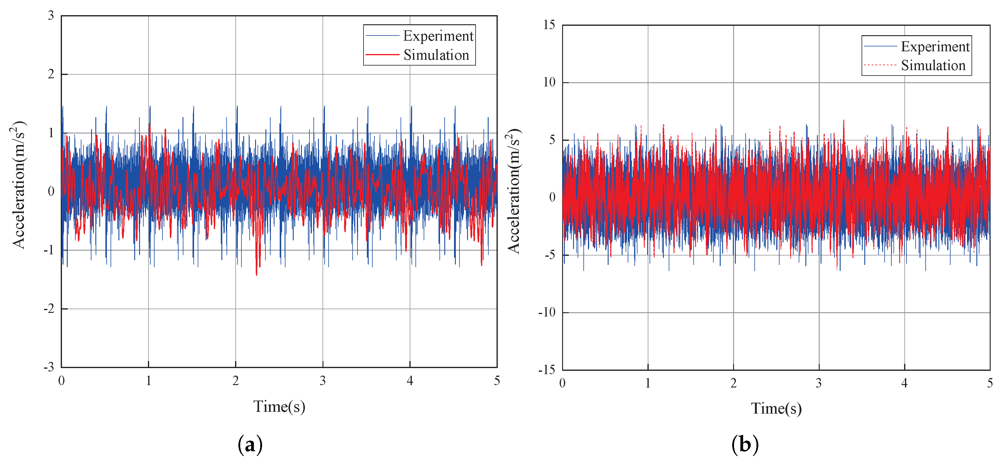
Existing studies have thoroughly examined the effects of wheel polygonization on wheel–rail contact, vehicle dynamics, and the vibrations of essential vehicle components. However, there is a noticeable gap in research regarding the influence of wheel polygonization on gear-meshing characteristics, especially within the context of urban railway vehicles. To address this, the present study utilizes a vehicle dynamics model that incorporates the gear-transmission system. It systematically investigates the impact of wheel polygon amplitude, order, and speed on gear-meshing forces, dynamic transmission error (DTE, defined as the deviation between ideal and actual gear-meshing caused by variations in load and alignment), and gear-meshing frequency, while specifically examining the effect of phase difference on gear-meshing forces, thereby contributing valuable insights to this underexplored area of research. Furthermore, this study combines experimental data with simulation results by installing sensors on the experimental vehicle to capture acceleration signals, which are subsequently compared with simulation outputs to validate the actual impact of wheel polygonization on the gear-transmission system. This integrated approach, combining experimental data and simulation analysis, significantly enhances the reliability of the findings and offers robust theoretical support for practical engineering applications.
This research focuses on examining how wheel polygonal wear influences the meshing behavior and dynamic performance of gear-transmission systems. The goal is to offer a solid scientific foundation for railway track maintenance while ensuring that the gear system effectively and accurately transmits power during vehicle operation, thereby supporting the smooth and stable functioning of trains. The findings are anticipated to contribute valuable insights into the safety and long-term reliability of railway transportation systems. Furthermore, the research will assist railway authorities in the development of fault prediction models, maintenance strategies, and repair protocols while identifying potential risks associated with polygonal wear, optimizing gear design, and mitigating the likelihood of system failures.
5. Discussion
5.1. Effect of Wheel Polygon Amplitude
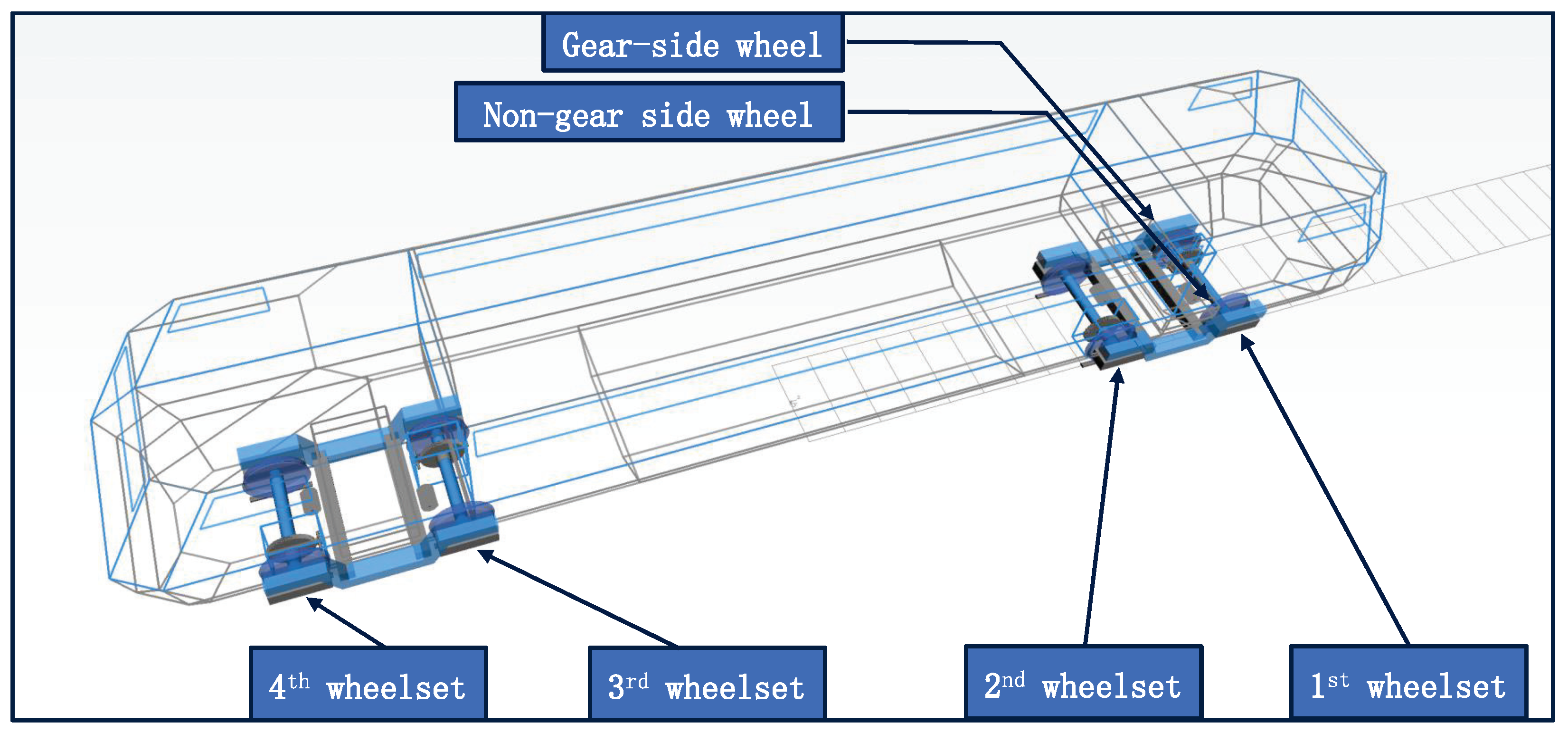
In this section, the wheel polygon is applied to the gear-side wheel of the first wheelset in the vehicle, with the fifth-order wheel polygon used as a case study and amplitudes of 0.02 mm, 0.06 mm, 0.1 mm, 0.14 mm, and 0.18 mm.
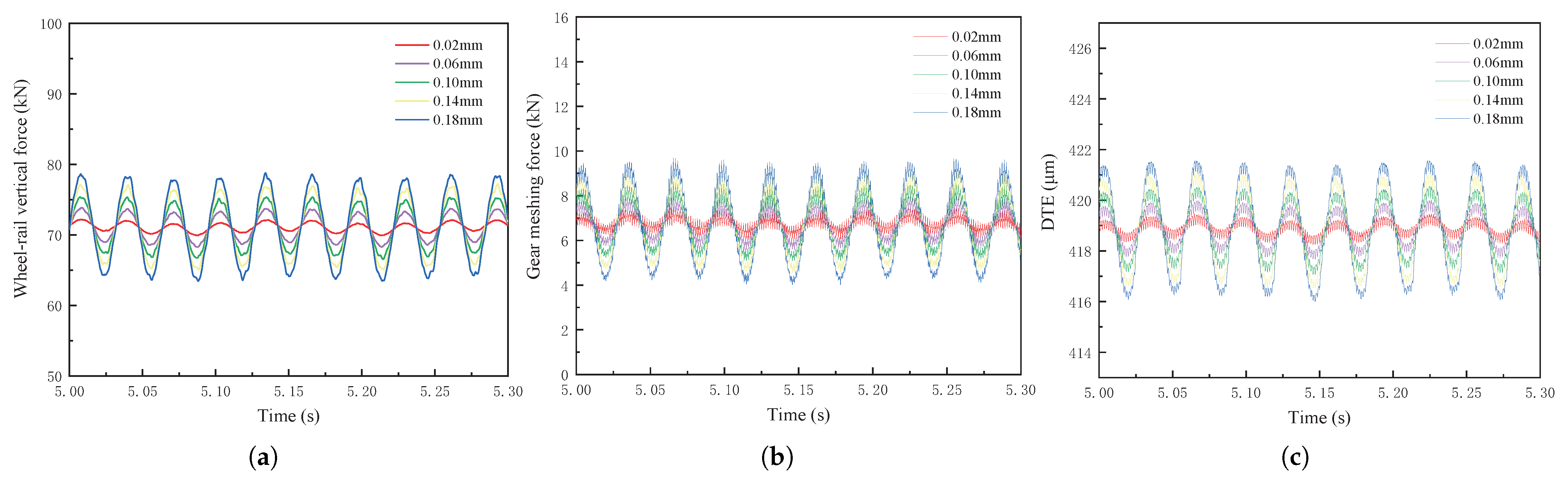
Figure 6 illustrates the time histories of the wheel–rail vertical force, gear-meshing force, and DTE for a vehicle traveling at a constant speed of 60 km/h. As the amplitude of the polygon increases, the amplitudes of the wheel–rail vertical force, gear-meshing force, and DTE increase significantly, accompanied by noticeable fluctuations. The overall vibration pattern displays a clear periodic variation.
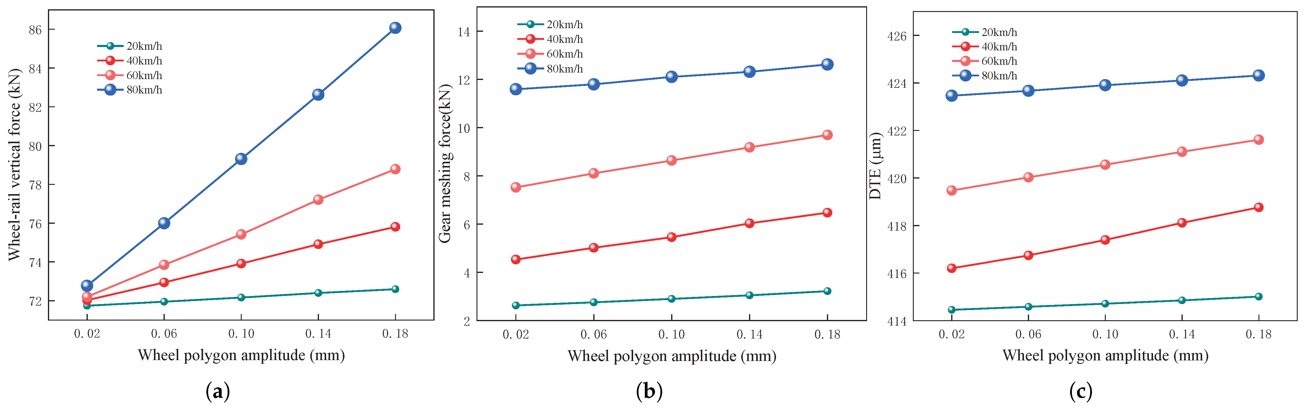
To further explore the interaction between vehicle speed and wheel polygon amplitude, as well as to assess the variations in wheel–rail vertical force, gear-meshing force, and DTE, simulations were conducted at different vehicle speeds. The peak values of these forces were analyzed to understand how they change with respect to both wheel polygon amplitude and vehicle speed. As depicted in
Figure 7, the impact of wheel polygon amplitude on wheel–rail vertical force becomes more noticeable with increasing vehicle speed. At a relatively low speed of 20 km/h, the variation in wheel–rail vertical force due to changes in polygon amplitude is minimal, increasing by only 1.19%, reaching a maximum of 72.59 kN. However, at higher speeds, the influence of wheel polygon amplitude on the wheel–rail vertical force becomes significantly greater. At 40 km/h, the force increases by 5.25%, reaching a peak of 75.80 kN; at 60 km/h, the force rises by 9.11%, reaching a maximum of 78.78 kN, and at 80 km/h, it increases by 18.27%, reaching a maximum of 86.07 kN. As vehicle speed increases, the effect of wheel polygon amplitude on the wheel–rail vertical force becomes more prominent. For a fixed wheel polygon amplitude, the vertical force rises by 1.43%, 5.62%, 9.90%, 14.12%, and 18.56% with increasing speed. This shows that the larger the wheel polygon amplitude, the more significant the effect of speed on the wheel–rail vertical force.
When the wheel polygon amplitude remains constant, the gear-meshing force increases with the vehicle’s speed. Notably, when the wheel polygon amplitude is 0.02 mm, the increase in gear-meshing force with speed is most pronounced, with the force at 80 km/h approximately 4.4 times that at 20 km/h, ranging from a minimum of 2.62 kN to a maximum of 11.59 kN. At the same speed, the gear-meshing force increases with the wheel polygon amplitude, though the rate of increase is smaller than that induced by the vehicle’s speed. At 20 km/h, the gear-meshing force increases by 22.64%, reaching a maximum of 3.22 kN. At 40 km/h, the gear-meshing force increases by 42.81%, reaching a maximum of 6.47 kN. At 60 km/h, the gear-meshing force increases by 28.86%, reaching a maximum of 9.69 kN. At 80 km/h, the gear-meshing force increases by 8.85%, reaching a maximum of 12.62 kN.
The trend in DTE variation follows a pattern similar to that of gear-meshing force, with both variables increasing as speed and wheel polygon amplitude rise. However, both variables show a gradual increase. The effect of vehicle speed on the DTE is significantly less pronounced compared to its effect on gear-meshing force. The wheel polygon amplitude of 0.18 mm shows the most pronounced increase in DTE with vehicle speed, rising by 2.24% at 80 km/h compared to 20 km/h. The minimum value is 415.01 m, and the maximum value is 424.31 m. At the same speed, the DTE increases marginally with the wheel polygon amplitude, rising by 0.13% at 20 km/h, with a maximum value of 415.01 m. At 40 km/h, the DTE increases by 0.61%, reaching a maximum value of 418.76 m. At 60 km/h, the DTE increases by 0.51%, reaching a maximum value of 421.61 m. At 80 km/h, the DTE increases by 0.20%, reaching a maximum value of 424.31 m.
5.2. Effect of Wheel Polygon Order
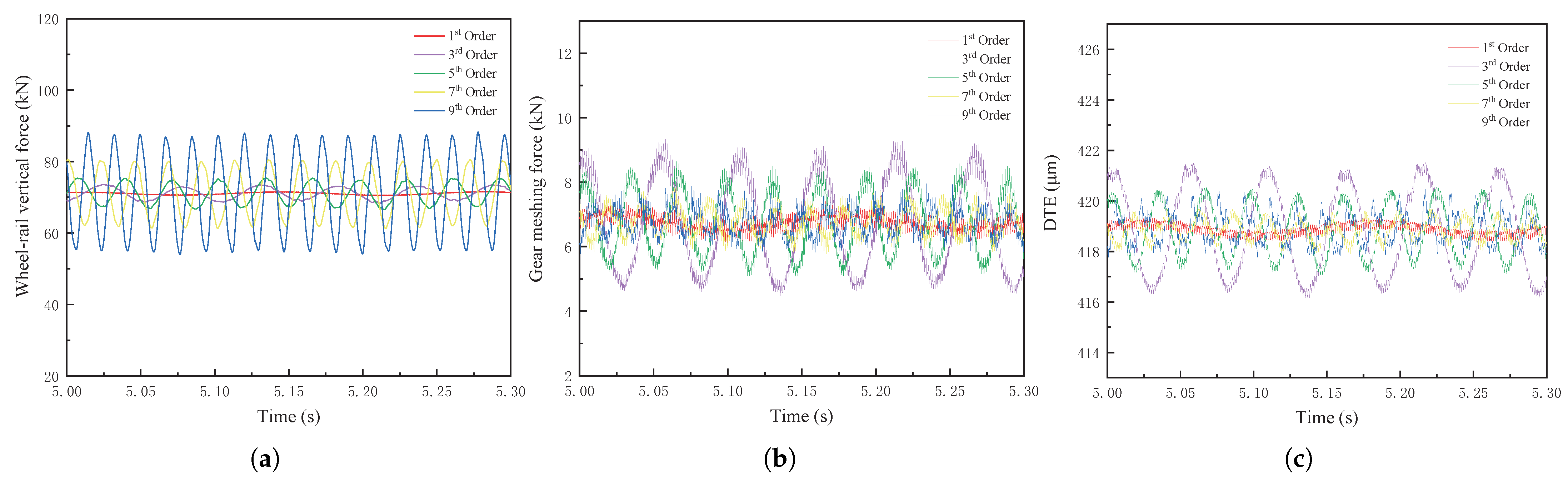
This section also applies the wheel polygon to the gear-side wheel, using a wheel polygon amplitude of 0.1 mm as an example and considering wheel polygon orders of 1, 3, 5, 7, and 9. It is illustrated in
Figure 8 that the temporal evolution of the wheel–rail vertical force, gear-meshing force, and DTE is shown at a constant speed of 60 km/h. As the wheel polygon order increases, the wheel–rail vertical force gradually increases, exhibiting pronounced fluctuations, with a maximum value of 88.32 kN at the ninth-order polygon. The meshing force and DTE initially increase, then decline, before gradually rising with the increase in wheel polygon order. The minimum values of the gear-meshing force and DTE are 7.44 kN and 419.34
m, respectively, at the first-order polygon, while the maximum values are 9.32 kN and 421.52
m, respectively, at the third-order polygon. Overall, the vibrations of the wheel–rail vertical force, gear-meshing force, and DTE intensify, exhibiting distinct cyclic fluctuations.
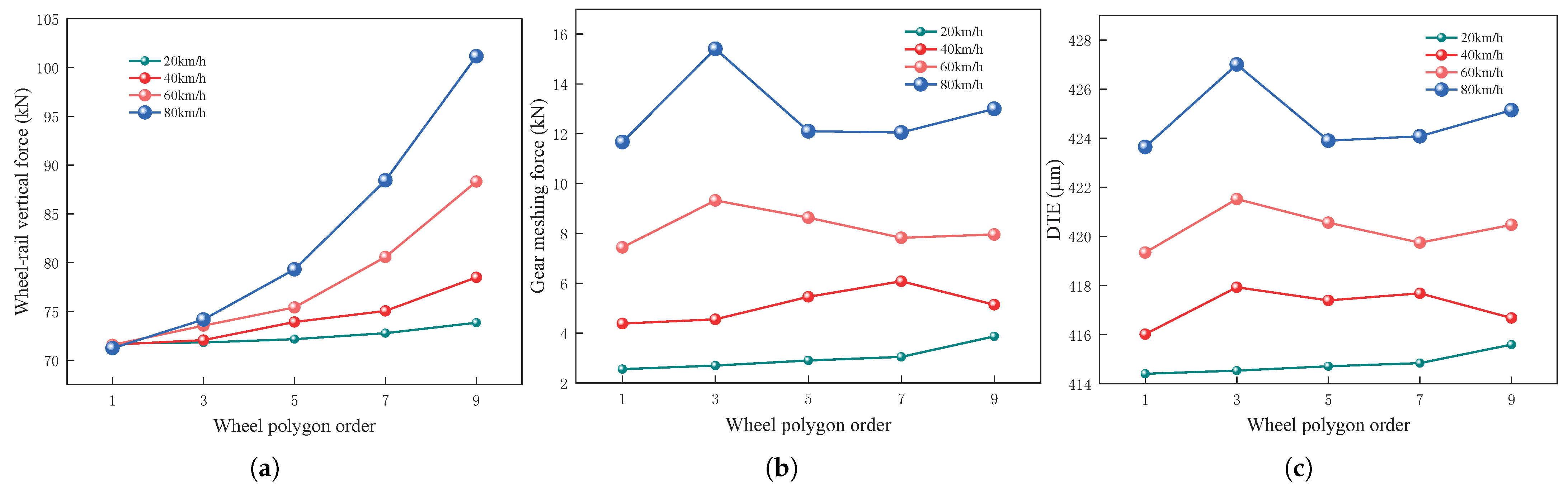
To further investigate the coupled influence of vehicle speed and wheel polygon order and to determine the trends in wheel–rail vertical force, gear-meshing force, and DTE, simulations were conducted at varying vehicle speeds. The peak values of these forces were observed at different vehicle speeds to analyze their trend variations in relation to wheel polygon order and vehicle speed. As shown in
Figure 9, an increase in vehicle speed leads to a more pronounced change in wheel–rail vertical force with respect to polygonal order. At a low speed of 20 km/h, the change in wheel–rail vertical force with polygonal order is minimal, increasing by only 2.94%, with a maximum value of 73.85 kN. At higher speeds, the wheel–rail vertical force shows a pronounced growth trend with increasing polygonal order. At 40 km/h, the wheel–rail vertical force increases by 9.63%, reaching a maximum value of 78.49 kN. At 60 km/h, the force increases by 23.40%, reaching a maximum value of 88.32 kN. At 80 km/h, the force increases by 42.01%, reaching a maximum value of 101.16 kN. As vehicle speed increases, the change in wheel–rail vertical force due to polygonal order becomes more pronounced. When the polygonal order is fixed, the wheel–rail vertical force increases with vehicle speed, reaching by −0.69%, 3.27%, 9.90%, 21.53%, and 36.99%, respectively. As polygon order increases, the change in wheel–rail vertical force due to vehicle speed becomes more pronounced.
The trends of gear-meshing force and DTE exhibited significant differences compared to those of wheel–rail vertical force. At 20 km/h, the gear-meshing force shows a gradual increase with the rise in wheel polygon order, reaching a minimum value of 2.56 kN and a maximum of 3.87 kN at the 9th-order polygon, reflecting a 51.34% increase. At 40 km/h, the gear-meshing force increases initially and then decreases with the rise in wheel polygon order, reaching a minimum value of 4.39 kN and a maximum of 6.08 kN at the 7th-order polygon, reflecting a 38.64% increase. At 60 km/h, the gear-meshing force increases initially and then decreases before the increase as the wheel polygon order rises, reaching a minimum value of 7.44 kN and a maximum of 9.32 kN at the 3rd-order polygon, reflecting a 25.33% increase. At 80 km/h, the gear-meshing force increases initially and then decreases before the increase as the wheel polygon order rises, reaching a minimum value of 11.67 kN and a maximum of 15.41 kN at the 3rd-order polygon, reflecting a 32.04% increase. When the wheel polygon order is fixed, the gear-meshing force increases with the growth of speed. Among these, the gear-meshing force shows the most pronounced variation with vehicle speed when the wheel polygon is of the 3rd order. At 80 km/h, the gear-meshing force is approximately 5.7 times that observed at 20 km/h, with a minimum value of 2.70 kN and a maximum of 15.41 kN.
The trend in DTE changes follows a similar pattern to that of the gear-meshing force; however, the overall increase is considerably less pronounced. At 20 km/h, the minimum recorded value of DTE is 414.41 m, while the maximum is 415.60 m, reflecting a 0.29% increase. At 40 km/h, the DTE exhibited notable values at the 3rd- and 7th-order polygons, which were 417.93 m and 417.68 m, respectively. The minimum value was 416.02 m, reflecting an increase of 0.46%. At 60 km/h, the DTE reaches a maximum value of 421.52 m at the 3rd-order polygon and a minimum value of 419.34 m, reflecting an increase of 0.52%. At 80 km/h, the DTE reaches a maximum value of 427.01 m at the 3rd-order polygon and a minimum value of 423.64 m, reflecting an increase of 0.79%. Similarly, when the wheel polygon order is fixed, the DTE tends to increase with the growth of vehicle speed, but the increase is much smaller than that of the gear-meshing force. Among these, the DTE exhibits the most significant variation with vehicle speed when the wheel polygon is of the 3rd order. Compared to the 20 km/h condition, the DTE increases by 3.00% at 80 km/h, with a minimum value of 414.53 m and a maximum value of 427.01 m.
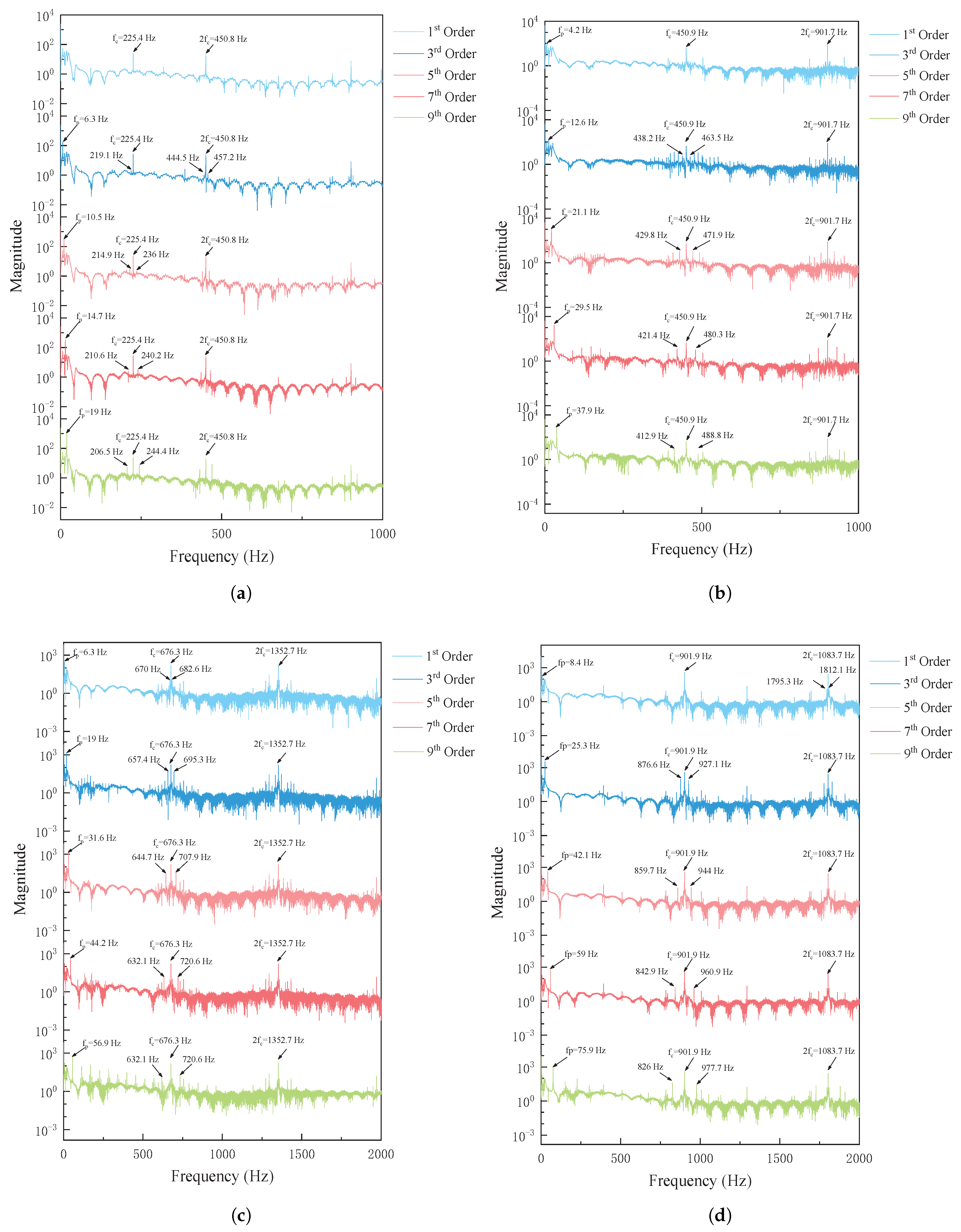
5.3. Wheel Polygon Excitation Frequency and Gear-Meshing Frequency
The gear-meshing frequency represents the rate at which the gear’s rigidity fluctuates during the meshing process, as defined by Equation (
7). Under the excitation of the gear-side wheel polygonization, distinct wave peaks appear in the gear-meshing force at frequencies of 225.4 Hz, 450.9 Hz, 676.3 Hz, and 901.8 Hz, corresponding to vehicle speeds of 20 km/h, 40 km/h, 60 km/h, and 80 km/h, respectively, as shown in
Figure 10. These peaks are directly associated with the gear-meshing frequency.
where
is the gear-meshing frequency,
is the rotational frequency of the pinion,
is the tooth number of the pinion,
is the rotational frequency of the gear,
is the tooth number of the gear.
In railway vehicle dynamics, wheel out-of-roundness refers to geometric deviations from a perfectly circular shape on the wheel tread [
4]. Polygonal out-of-roundness caused by polygonalization, a typical wheel out-of-roundness, is a predominant wheel tread defect in rail vehicles [
43]. This study investigates the polygonal wheel characterized by periodic radial tread deviations from the health wheel radius. The corresponding excitation frequency is expressed in Equation (
8).
where
is the wheel polygon excitation frequency,
N is the wheel polygon order,
is the vehicle operating speed,
R is the wheel radius.
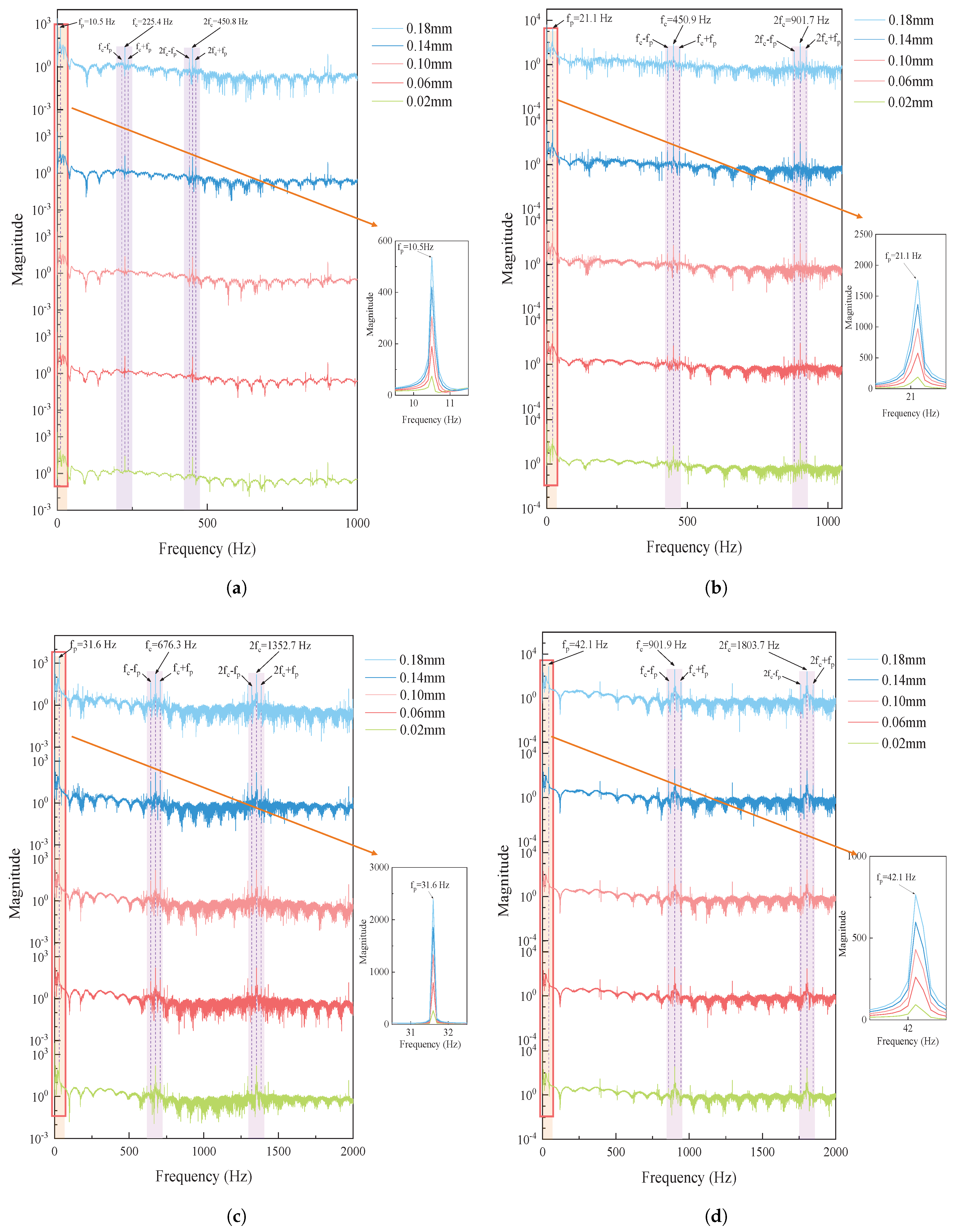
The gear-meshing frequency is influenced by the system’s structural parameters, whereas the wheel polygon excitation frequency is dictated by the polygon order and vehicle speed, remaining independent of the polygon amplitude. As illustrated in
Figure 11, both the wheel polygon excitation frequency and gear-meshing frequency increase linearly with vehicle speed. The gear-meshing frequency remains significantly higher than the wheel polygon excitation frequency, indicating that the wheel polygon primarily acts as a low-frequency modulation source, introducing periodic perturbations to the gear system. For instance, considering a 5th-order wheel polygon, when the vehicle speed rises from 20 km/h to 80 km/h, the excitation frequency increases from 10.5 Hz to 42.1 Hz, while the gear-meshing frequency grows proportionally from 225.4 Hz to 901.9 Hz. Furthermore, at a constant speed, the wheel polygon excitation amplitude increases with polygon amplitude, peaking at 60 km/h before slightly decreasing at higher speeds, potentially due to the damping and dynamic characteristics of the system.
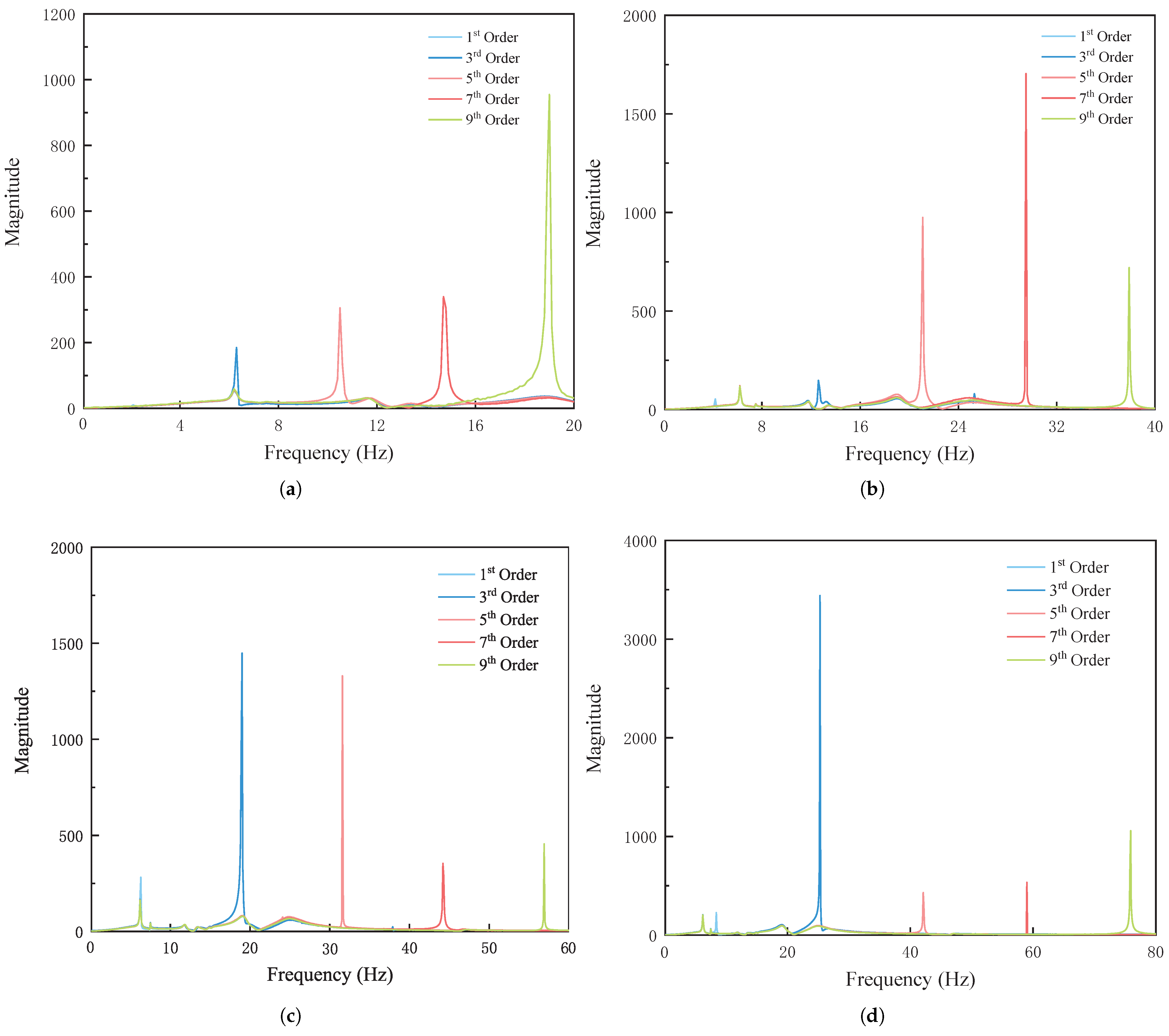
As shown in
Figure 12 and
Figure 13, the excitation frequency of the wheel polygon is determined by its order and vehicle speed, increasing linearly with speed. Meanwhile, the excitation amplitude is modulated by the polygon order, exhibiting distinct dominant order characteristics at different speeds. At 20 km/h, the excitation amplitude increases with polygon order, indicating that higher-order polygons have a more pronounced effect at low speeds. At 40 km/h, the excitation amplitude of the 7th-order polygon is the highest, suggesting that this order exerts the strongest perturbation effect on the system. At 60 km/h and 80 km/h, the 3rd-order polygon exhibits the highest excitation amplitude, demonstrating that lower-order polygons play a more dominant role in the gear system at medium and high speeds.
5.4. Effect of Wheel Polygonization Phase Differences
The development of wheel polygon wear is often complex. Typically, a phase difference exists between the waveforms of the same pair of wheel polygon wear, making the excitation with a phase difference more representative of real-world conditions. Consequently, the wheel polygon excitation with a phase difference more accurately reflects actual operational scenarios. Compared to in-phase wheel polygon excitation, excitation with a phase difference is superimposed on other forms of excitation, in addition to vertical excitation, leading to a more comprehensive representation of dynamic effects.
Through previous analyses, we have determined that vehicle speed and wheel polygon order have a significant impact on the gear-meshing force. Therefore, in this section, we select a wheel polygon amplitude of 0.1 mm and impose the same polygon order and amplitude on both sides of the wheel to ensure consistent testing conditions. Specifically, we vary the initial phase of the gear-side wheel polygon in the mathematical model from 0° to 180° while maintaining the initial phase of the non-gear-side wheel polygon at 0° across different speeds and wheel polygon orders. The specific wheel polygon phase conditions are presented in
Table 4.
Figure 14,
Figure 15,
Figure 16 and
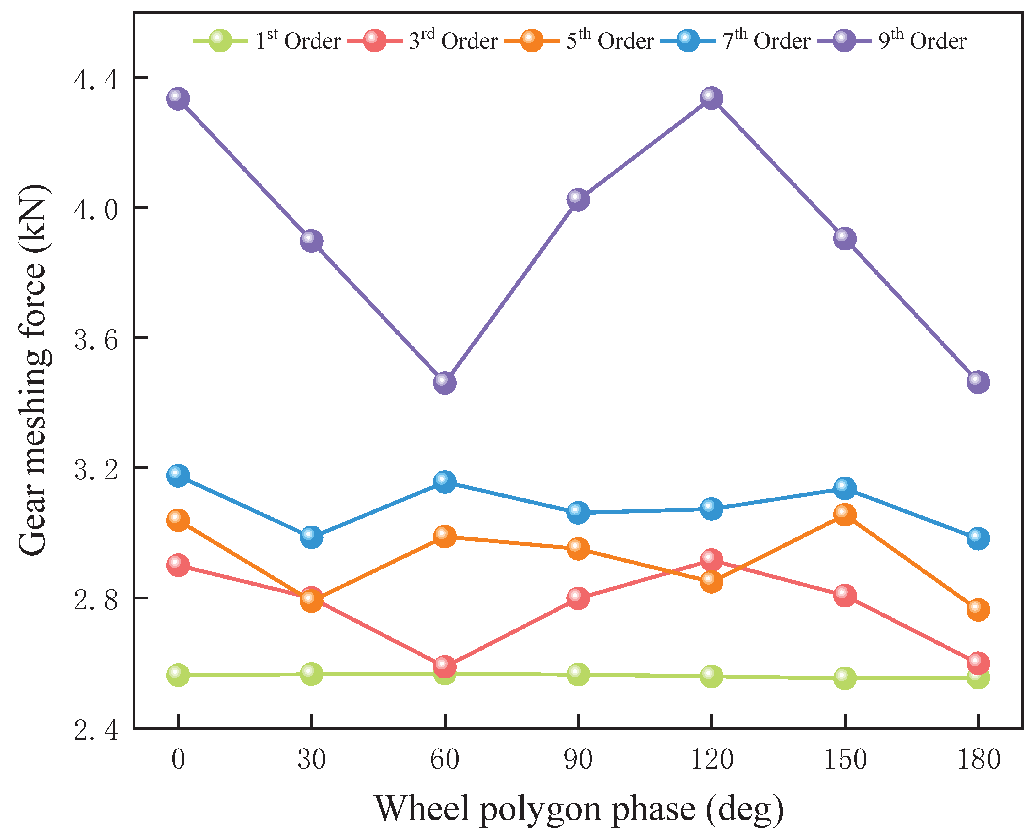
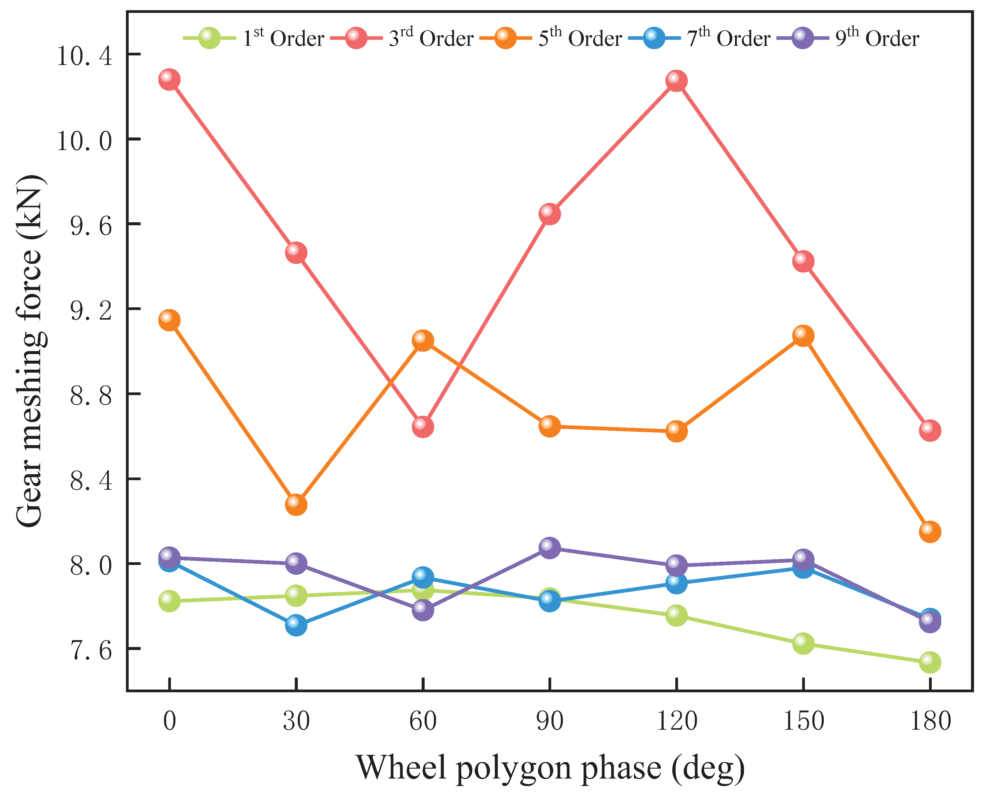
Figure 17 illustrate the maximum dynamic response of the gear-meshing force under varying speeds, wheel polygon orders, and different wheel polygon phase differences. The gear-meshing force exhibits distinct trends as the wheel polygon phase difference changes across different speeds and polygon orders. Under different speed conditions, the maximum gear-meshing force induced by the first-order wheel polygon remains relatively stable with respect to phase differences. It exhibits minimal variations at 20 km/h and 40 km/h and a slight decreasing trend at 60 km/h and 80 km/h.
As shown in
Figure 14, under the operating condition of 20 km/h, the wheel polygon exhibits similar behavior at the 5th and 7th orders, with local minima at phase differences of 30° and 120° and local maxima at 60° and 150°. The fluctuation amplitudes are 10.58% and 6.49%, respectively, indicating that the phase difference has a relatively minor effect. Similarly, for the 3rd and 9th orders, the wheel polygon follows a comparable trend, with local minima and maxima appearing at 60° and 120° phase differences, respectively. The corresponding fluctuation amplitudes are approximately 12.66% and 25.32%, exhibiting greater variations.
As shown in
Figure 15, at 40 km/h, the gear-meshing force of the 3rd-order wheel polygon reaches a minimum at a phase difference of 90°, with local peaks at 30° and 150°, and an overall fluctuation amplitude of 8.95%, which is significantly lower than that at 20 km/h. In the 5th-order wheel polygon, the meshing force exhibits a local peak at a 60° phase difference, with an overall fluctuation amplitude of 6.29%, similar to that at 20 km/h. For the 7th-order wheel polygon, the meshing force has local minima at 30° and 120° phase differences and local peaks at 60° and 150°, with a fluctuation amplitude of 16.95%, representing a substantial increase from 6.5% at 20 km/h. This suggests that the influence of the 7th-order engagement force is amplified as vehicle speed increases. In contrast, for the 9th-order wheel polygon, local minima and maxima occur at 60° and 120° phase differences, respectively, with fluctuation amplitudes of 9.00%, significantly lower than the 25.32% observed at 20 km/h. This reduction indicates that the influence of higher-order components diminishes at higher speeds.
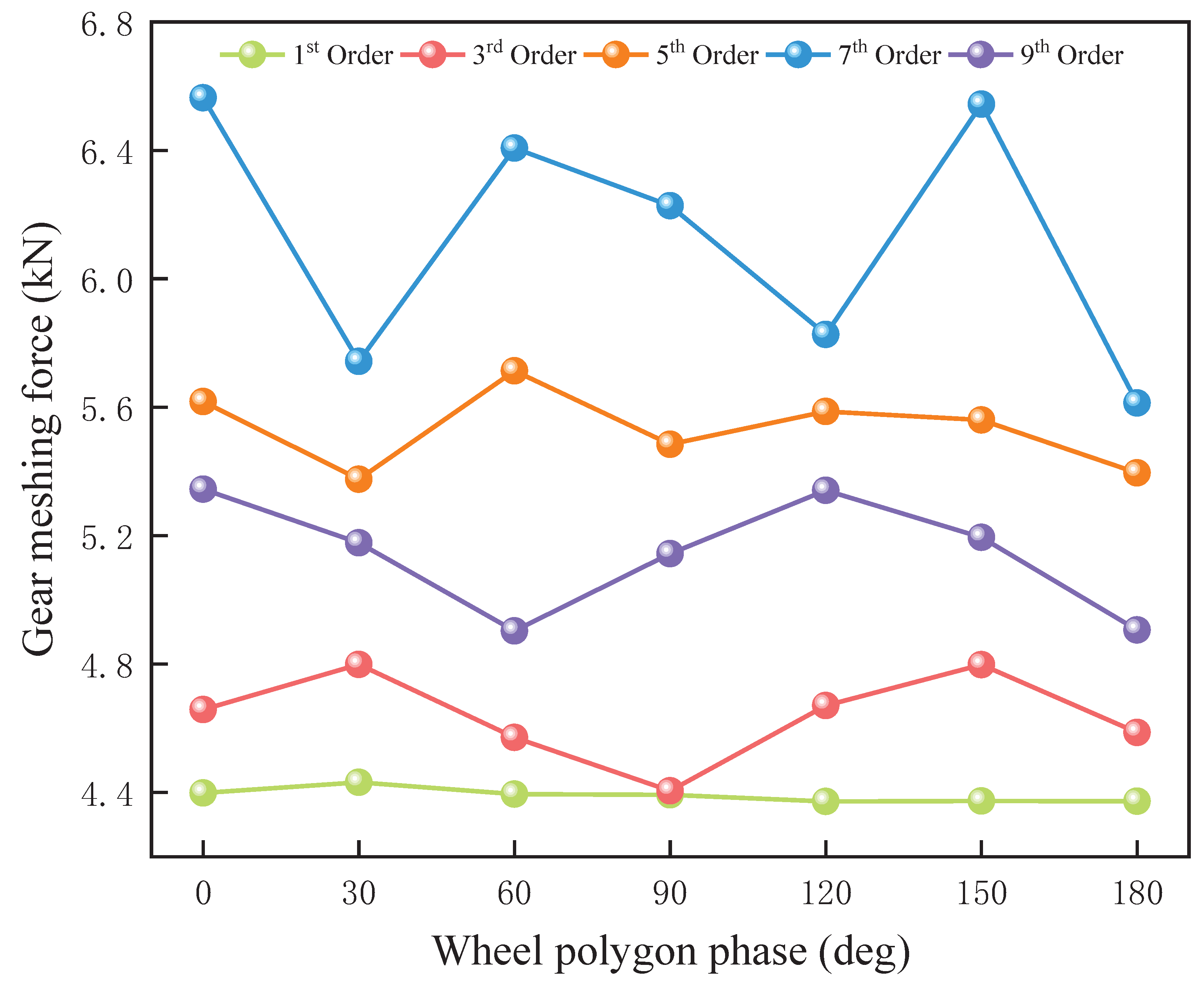
As shown in
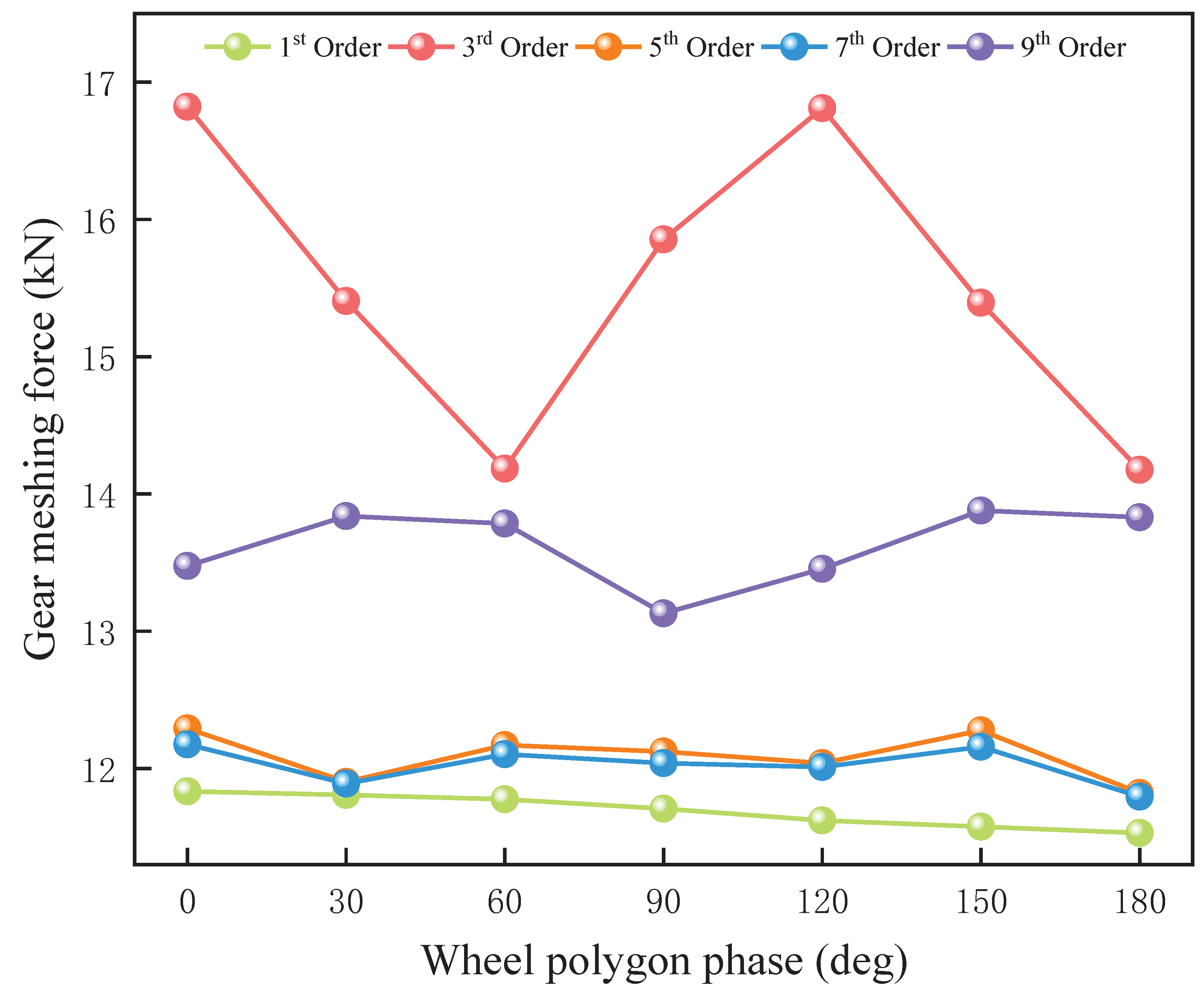
Figure 16, at 60 km/h, the fluctuation amplitudes of the 7th- and 9th-order wheel polygons are 3.92% and 4.51%, respectively, both relatively small. The 5th-order polygon exhibits local peaks at 60° and 150° phase differences and a local minimum at 30°, with an overall fluctuation amplitude of 12.24%. This value is higher than those observed at 20 km/h and 40 km/h, indicating that the influence of the 5th-order component increases with speed. Additionally, the third-order gear-meshing force reaches a local minimum at a 60° phase difference and a local maximum at 120°, with a fluctuation amplitude of 19.17%, marking a significant increase compared to 8.95% at 40 km/h. This suggests that the third-order component’s impact on the gear-meshing force intensifies as vehicle speed rises. Furthermore, while the fluctuation of higher-order components tends to diminish as speed increases, the fluctuation amplitudes of lower-order components, particularly the third- and fifth-order polygons, become more pronounced. This indicates that at higher speeds, lower-order wheel polygons exert a more significant influence on the meshing force.
As shown in
Figure 17, under the 80 km/h condition, the trends of the fifth- and seventh-order wheel polygons are highly similar, with fluctuation amplitudes of 3.97% and 3.23%, respectively. These values are lower than those observed at 60 km/h, indicating that the effects of the fifth- and seventh-order components tend to stabilize at higher speeds. The fluctuation of the ninth-order meshing force is noticeable, though its amplitude remains small. A local minimum occurs at a phase difference of 90°, with a fluctuation amplitude of 5.70%, slightly higher than the 4.51% observed at 60 km/h, suggesting that higher-order components still exhibit some fluctuation at high speeds. Additionally, the third-order polygon exhibits local minimum and maximum values at phase differences of 60° and 120°, respectively, with a fluctuation amplitude of 18.65%. This is comparable to the 19.17% fluctuation of the third-order polygon at 60 km/h but significantly higher than the 8.95% recorded at 40 km/h. These findings indicate that the influence of the third-order component on the meshing force remains substantial at high speeds.
Based on the previous analyses, the maximum gear-meshing force under the operating conditions of 20 km/h, 40 km/h, 60 km/h, and 80 km/h appears in the 9th-order, 7th-order, and 3rd-order wheel polygons, respectively. This observation suggests that as the meshing force increases, the influence of the wheel polygon’s phase difference becomes more pronounced. Additionally, under these conditions, the forces exhibit local maxima and minima at phase differences of 60° and 120°, corresponding to in-phase and complete phase reversal, respectively.
The phase difference of the wheel polygon determines whether the polygonal excitations of the left and right wheels are superimposed and amplified or partially canceled, thereby influencing the magnitude of the gear-meshing force. When the left and right wheel polygon phases are in-phase or completely out-of-phase, the synthesized wheel–rail excitation reaches its extremes. In the in-phase condition, the wheel–rail excitations are fully synchronized, leading to an increase in the peak meshing force. Conversely, when completely out of phase, the excitation waveforms of the left and right wheels cancel each other out, resulting in a reduction in the meshing force. At phase differences of 60° and 120°, the excitations of the left and right wheels are either partially superimposed or staggered, influencing the resonance characteristics of the gear system and leading to the occurrence of local maxima and minima.
6. Conclusions
This study establishes a theoretical foundation for wheel re-profiling practices, aiming to provide practical guidance for enhancing the reliability and performance of railway transportation systems. The findings demonstrate that wheel polygonization effects—encompassing order, amplitude, and phase difference—significantly influence the dynamic behavior of gear systems, particularly in urban rail vehicles.
Low-order wheel polygonization, especially at medium to high speeds, exerts a more substantial impact on the gear-meshing force. Conversely, high-order wheel polygonization has a more pronounced effect under low-speed conditions. This observation suggests that wheel re-profiling strategies should prioritize the influence of low-order wheel polygonization, particularly at higher operational speeds, by optimizing wheel shape to mitigate its adverse effects on the gear system. This adjustment would enhance gear-meshing characteristics and reduce system vibrations. Furthermore, the amplitude of wheel polygonization plays a crucial role in system dynamics, particularly at higher speeds, where increased amplitudes significantly exacerbate the system’s dynamic response.
The excitation frequency of wheel polygonization is influenced by both vehicle speed and order. As vehicle speed and wheel polygonization amplitude increase, excitation amplitude gradually rises, peaking at 60 km/h, and subsequently decreases at higher speeds. At lower speeds, the impact of high-order polygonization is more significant, whereas at medium to high speeds, the modulation effect of low-order polygonization becomes more prominent, and the gear system’s sensitivity to wheel polygonization excitation increases. Consequently, when designing gear-transmission systems and rail vehicles, it is critical to comprehensively consider the effects of vehicle speed, wheel polygonization amplitude, and order in order to minimize the vibrational impact on system stability and operational reliability.
The influence of phase difference in wheel polygonization on gear-meshing force should not be underestimated, particularly when the phase difference is 0° (in-phase) or 180° (completely out-of-phase), or when the phase difference is 60° and 120°, as these conditions lead to excessive excitation, adversely affecting gear-meshing force and overall system performance. Therefore, special attention should be given to these phase differences during wheel re-profiling to prevent excessive excitation and enhance the stability and reliability of the gear system.
This study provides valuable guidance for wheel re-profiling and gear system design. Railway operators and maintenance departments can apply these findings to monitor and adjust low-order wheel polygonization in practical operations, especially under high-speed conditions, and promptly modify wheel profiles to improve gear system reliability and stability. Future research will integrate wheel re-profiling strategies, gear design, and maintenance optimization, exploring the impact of low-order wheel polygonization, high-amplitude wheel polygonization, and phase difference on gear system performance. Particularly under medium to high-speed conditions, enhancing wheel re-profiling strategies, optimizing gear design, and developing effective maintenance strategies will help achieve improved stability and reliability of the gear system.
Furthermore, future research will expand to include a broader range of rail vehicles, track, wheel system flexibility, and other critical vehicle components, aiming to enhance the overall operational efficiency and safety of the system. This body of research will provide a robust theoretical framework for the technological advancement of railway transportation systems and offer valuable practical insights for improving the operational reliability and safety of urban rail transportation.


