Abstract
Mobile welding robots have attracted considerable attention due to their flexible movement and robust adaptability, offering substantial market potential. However, the complexity of their operational conditions poses specific demands on robot configurations, with no established design methodology available at the time. To address this challenge, we constructed Lagrange’s equations for wheeled mobile welding robots. Through simplification and deduction analysis, we concluded that larger wheeled mobile welding robots are suited for paths with larger curvature radii, whereas smaller ones are more appropriate for paths with smaller curvature radii. Based on the above analysis and considering the load-bearing capacity of the robot, we proposed a configuration design method for wheeled mobile welding robots, evolving from large to small and micro wheels, including track constraints and wheel number adjustments. Subsequently, prototype robots, including magnetic wheel, tracked, and flexible contour tracing mobile welding robots, have been developed to accommodate various operational conditions. Welding experiments demonstrate that these three configurations, distinguished by their travel path curvature radii, can effectively meet the mobile welding requirements of their respective environments. The effectiveness of the configuration design of wheeled mobile welding robots under different working conditions has been verified.
1. Introduction
Mobile welding robots incorporate advanced technologies, including robot configuration design, robotic arm technology, sensor technology, and intelligent control technology. They offer advantages such as flexible mobility, strong adaptability, and a wide range of applications, enabling them to perform adaptive welding tasks under complex working conditions [1,2,3,4]. In comparison with industrial welding robots, mobile welding robots exhibit flexible and variable configurations, are easy to transport, and possess significant application potential in field construction [5,6,7,8]. In recent years, related research on mobile welding robots has been carried out both domestically and internationally, yielding certain outcomes [9,10,11,12].
Suga et al. developed a three-wheeled mobile welding robot, which is applicable to the automated welding operations of thin plates with a large curvature radius [13]. Ngo et al. developed a relatively small two-wheeled drive mobile welding robot, which can be utilized for the automated welding construction of right-angle welds on the rib plates in narrow ship cabins [14]. Lyu et al. developed a four-wheeled mobile welding robot, enabling the realization of automatic welding on the surfaces of large-scale steel structures such as ship decks [15]. Shang et al. conducted research and development on a multi-body cooperative mobile welding robot, where multiple robots collaborate to complete the automated welding tasks of large-scale steel components [16]. All the aforementioned robots are capable of moving on the surfaces of workpieces with a relatively large curvature radius. However, due to the constraints of their configurations and working conditions, they encounter difficulties in completing all-position welding operations on the surfaces of workpieces with a small curvature radius [17,18,19]. To expand the application scope of mobile welding robots, therefore, rail-based mobile welding robots have emerged. Suga et al. developed a rail-based mobile welding robot for pipe butt-weld welding [20]. Ang et al. developed a large-scale teaching-type welding robot system (SWERS) based on a portal-frame rail, which is applied to the welding of open-air ship steel structures [21]. Liang et al. developed an all-position mobile welding robot based on a flexible rail, which is capable of performing all-position welding operations on the weld seams of the surfaces of irregular workpieces [22].
The research and development of the aforementioned mobile welding robots have significantly promoted the progress in the field of welding automation. Nevertheless, due to volume and load constraints, conventional mobile welding robots encounter difficulties in completing automatic welding operations within narrow spaces [23,24]. Moreover, in the face of the complex and variable welding working conditions in the practical field, there still lacks a systematic configuration design methodology for mobile welding robots that can be referred to both at home and abroad. Therefore, it is of great urgency to explore the potential inherent relationships between welding robot configurations and welding working conditions, with the aim of providing valuable references for the configuration design of mobile welding robots under complex working conditions [25,26,27,28].
Based on the aforementioned background, we propose to characterize the operational environment of a mobile welding robot by the curvature radius of its travel path. Firstly, the Lagrange’s equation is formulated to model the motion of the wheeled mobile welding robot. Through numerical simulation analysis, it is concluded that welding conditions with larger curvature radii are suitable for wheeled mobile welding robots with larger wheels, while those with smaller curvature radii are better suited for robots with smaller wheels. Considering the robot’s load-bearing capacity, a configuration design concept for the wheeled mobile welding robot is developed, which evolves from large wheels to small wheels and then to micro wheels, complemented by track constraints and an increase in the number of wheels. Subsequently, a configuration design function for the wheeled mobile welding robot under multiple conditions is constructed, and a design process for multi-condition wheeled mobile welding robots is proposed. Finally, prototypes of wheeled mobile welding robots for three typical operational environments are manufactured and subjected to welding experiments. The experimental results validate the effectiveness of the proposed configuration design methodology for wheeled mobile welding robots under various conditions, providing a reference for the configuration design of wheeled mobile welding robots in complex and unknown working environments.
2. Design Philosophy
Mobile welding robots are classified into wheeled, tracked, legged, and hybrid structures based on their differing travel modes. Among these, wheeled and tracked mobile welding robots are the most widely used due to their uncomplicated structures and high-speed movement efficiency. A wheeled welding cart is characterized by its simple structure, high-speed movement, agile turning capabilities, and straightforward control. Therefore, this paper focuses on research related to wheeled mobile welding robots [29,30]. In fact, the tracked mobile welding robot can be considered a special type of wheeled mobile welding robot, where the moving track consists of multiple small wheels forming a track wheel that offers a certain degree of flexibility, thus granting it enhanced obstacle-crossing capabilities and superior adaptability in unstructured environments.
The operation of wheeled mobile welding robots is significantly influenced by the road conditions within the working environment. To adapt to specific working conditions, an appropriate robot configuration must be selected. Therefore, this paper proposes representing the welding working conditions by using the curvature radius of the welding robot’s traveling path. Figure 1 illustrates the schematic diagram of the configuration design of the wheeled welding cart under working conditions with different curvature radii.
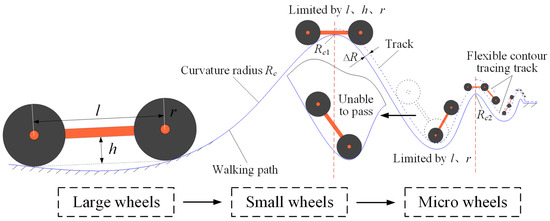
Figure 1.
Configuration design philosophy for wheeled mobile welding carts under different paths.
As can be seen from Figure 1, the passability of wheeled mobile welding robots across curved surfaces of workpieces to be welded is influenced by factors such as the structural parameters of the robot body and the curvature radius of the travel path. Based on practical engineering experience, the size of the robot should be matched to the geometric conditions of the travel path. For relatively flat travel paths with larger curvature radii throughout, it is suitable to deploy larger wheeled mobile welding robots for operations, as they offer good stability and strong load-bearing capacity. Conversely, for travel path conditions with smaller curvature radii, smaller wheeled mobile welding robots are preferable, as their motion states are easier to control and they respond more quickly. To ensure the accuracy of the above design concept for wheeled mobile welding robots, the Lagrange’s equations for these robots are formulated for analysis and verification.
Assuming the mass of the wheeled mobile welding robot as m, it moves along a path with varying curvature radius, represented by the curve equation r(s), where s is the arc length parameter. Given that the welding path exhibits certain variations in height within the space, its height function is denoted as h(s). The external forces acting on the robot include driving force Fd, friction force Ff, and gravitational force mg. For a complete system with multiple degrees of freedom, the general form of the Lagrange’s equation [31,32] is given by:
where qi denotes the generalized coordinates, denotes the generalized velocities, and Qi represents the generalized forces corresponding to the coordinates, wherein Lagrange’s function L is defined as:
where T represents the kinetic energy of the system, and V represents the potential energy of the system. Assuming that the turning angle of the robot during its movement is θ, and this angle can be regarded as a function of arc length, that is, θ = θ(s). Let u = ds/dt; then, we can obtain:
Ignoring the rotational kinetic energy, kinetic energy T and potential energy V can be expressed as:
Substituting Equations (3) and (4) into Equation (2) yields:
Combining Equation (1), Lagrange’s equation for the motion of the wheeled mobile welding robot can be expressed as:
where represents the generalized velocity, and Q represents the generalized force, with the following relationships:
According to the derivative formula for composite functions, we can obtain:
Substituting Equations (7) and (8) into Equation (6), we can then perform differentiation and expansion to obtain:
We can then organize the relevant terms in Equation (9) and represent them using fixed parameters as follows:
In Equation (10), A represents a constant related to the path, C denotes the curvature-related term, D represents a rotation-related term (assumed to be constant), E denotes a rotation-related constant, and H represents the reciprocal constant of the height function. By combining the relevant terms based on the actual physical meanings of the expressions in the Lagrange’s function equation, Equation (9) can be organized as follows:
Equation (11) is a nonlinear equation concerning the generalized velocity u and its rate of change du/dt. It is difficult to quantitatively analyze the exact relationship through analytical methods. Instead, the equation can be approximately solved using Newton’s iteration method, which constructs a linear equation using the first and second derivatives (or Taylor expansion) of the function at a given point. The solution to this linear equation serves as an approximate solution to the original equation, and by repeatedly iterating this process, one can gradually approximate the exact solution of the original equation. Assuming that the mass m of the welding robot is proportional to its volume V, that is, m = C1V (where C1 is a constant), we assign values to the parameters in the equation. The numerical relationship contour plots in Figure 2 and Figure 3 show the relationships between the generalized velocity u (and its rate of change du/dt) and the factors of curvature κ and mass m, respectively.
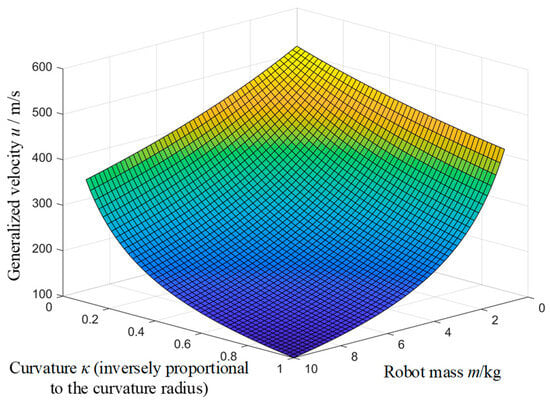
Figure 2.
The numerical simulation plot among curvature κ, mass m, and generalized velocity u.
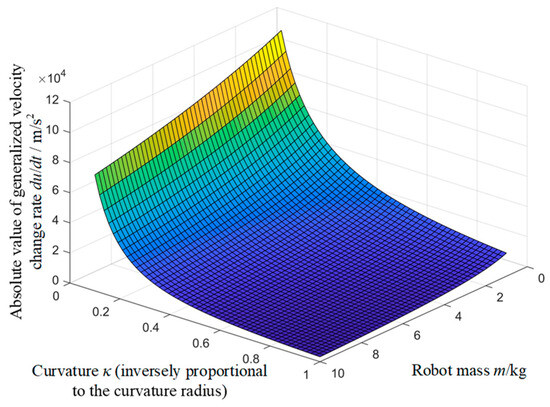
Figure 3.
The numerical simulation plot among curvature κ, mass m, and the rate of change of generalized velocity du/dt.
Based on the numerical simulation results, it can be concluded that when the path curvature radius is large (that is, the curvature κ is small), the generalized velocity u exhibits a relatively flat variation with respect to the mass m, and the rate of change of generalized velocity du/dt remains relatively stable within a certain range. At this point, the motion state of the mobile welding robot is less sensitive to changes in mass. Robots with larger masses demonstrate stronger anti-interference capabilities during motion, with their velocity and motion state being easier to maintain constant, resulting in better stability. Similarly, when the curvature radius is small (that is, the curvature κ is large), the generalized velocity u and the rate of change of generalized velocity du/dt exhibit more significant variations with respect to the mass m. In such cases, mobile welding robots with smaller masses can more flexibly respond to rapid changes in curvature, thereby enabling better maneuverability along complex paths. Based on the above analysis, it can be inferred that paths with larger curvature radii are suitable for wheeled mobile welding robots with larger volumes, while paths with smaller curvature radii are suitable for wheeled mobile welding robots with smaller volumes.
As the curvature radius of the travel path decreases, the size of the wheeled mobile welding robot, which is matched to this path, decreases accordingly. Let us define the following terms: Ml represents the total mass of the robot body, welding torch, and other associated loads; g denotes gravitational acceleration; Cw represents the deformation coefficient of the wheel material; and S denotes the equivalent contact area between the wheel and the path. Based on the elastic deformation theory, derived from Hooke’s Law, the deformation amount of the robot’s wheel on the horizontal plane of the path can be formulated as follows:
As the overall volume of the robot decreases, the volume of the wheels diminishes accordingly, leading to a reduction in the contact area S. Under the premise that other conditions remain unchanged, the deformation δ increases, which can easily cause the wheels to deviate from the path or impair the robot’s stable movement. Therefore, an increase in the number of wheels is necessary to enhance its load-bearing capacity. Based on the above analysis, the following design approach for the configuration of wheeled mobile welding robots under multiple conditions is formulated: in welding scenarios where the curvature radius of the travel path continuously decreases, the volume of the compatible wheeled mobile welding robot also evolves from large to small. When the robot’s volume reaches a certain small size, it can lead to issues of poor stability and inadequate load-bearing capacity for the wheeled mobile welding robot. At this point, the addition of track constraints is required to improve its stability, while simultaneously increasing the number of wheels to enhance its load-bearing capacity.
3. Configuration Design of Robots
Based on the configuration design philosophy of wheeled mobile welding robots, the configuration of these robots is characterized by track constraints, varies specifically with curvature radius under different working conditions for wheeled mobile welding units, and is influenced by load conditions. A multi-condition configuration design function G(k) for wheeled mobile welding robots, incorporating considerations for large wheels, small wheels, and micro wheels, is constructed, as illustrated in Equation (13).
where f denotes the configuration design function of the wheeled mobile welding robot under specific working conditions, while g represents the configuration design function of the wheeled welding cart. ΔRs indicates the configuration design with additional track constraints, and ΔRm indicates the configuration design with additional flexible contour track constraints. r refers to the radius of the wheels of the welding cart, h represents the distance between the bottom plate of the cart body and the ground, l denotes the wheelbase between the front and rear wheels, and w represents the total width of the cart body. N signifies the number of micro wheeled mobile welding carts, and K represents the load borne by the robot. λ1, λ2, and λ3 are all load coefficients. Rc represents the curvature radius values at various positions along the welding travel path of the robot. Rc1 and Rc2, respectively, denote the boundary values between the larger and smaller curvature radii, and between the smaller and extremely small curvature radii of the mobile welding robot’s travel path curvature radius. Their values can be flexibly determined according to the actual working conditions. Typically, Rc1 is set within the range of 800 mm to 1000 mm, and Rc2 is usually set within the range of 150 mm to 250 mm.
In Equation (13), k = 1 denotes the configuration of the wheeled mobile welding robot based on large wheels. When the curvature radii of the traveling path are all greater than or equal to Rc1, this configuration mainly depends on key influencing factors such as the configuration of the welding cart and the load of the welding torch. The schematic diagram of this robot configuration design is shown in Figure 4a. k = 2 represents the configuration of the rail-mounted wheeled mobile welding robot based on small wheels. The operating condition for this configuration is when there exists a curvature radius of the traveling path that is less than Rc1, while ensuring all curvature radii are no less than Rc2. This robot configuration mainly hinges on key influencing factors such as the constraint track, the configuration of the welding cart, and the load of the welding torch. The schematic diagram of this robot configuration design is shown in Figure 4b. k = 3 represents the configuration of the flexible contour tracing wheeled mobile welding robot based on micro wheels. The operating condition for this configuration is when there exists a curvature radius of the traveling path that is less than Rc2. This robot configuration mainly relies on key influencing factors such as the flexible contour constraint track, the configuration and quantity of the micro wheeled welding cart, and the load of the welding torch. The schematic diagram of this robot configuration design is shown in Figure 4c.
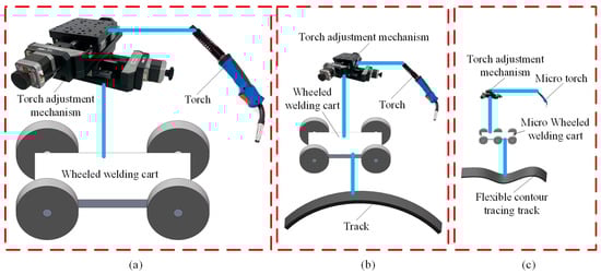
Figure 4.
Wheeled mobile welding robot configuration under multiple working conditions. (a) Robot configuration based on large wheels when k = 1; (b) Robot configuration based on small wheels when k = 2; (c) Robot configuration based on micro wheels when k = 3.
Based on the above analysis and in combination with the actual engineering design requirements, a configuration design process for wheeled mobile welding robots that operate under multiple conditions is proposed. Subsequently, the specific process is illustrated in Figure 5.
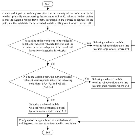
Figure 5.
Configuration design process for wheeled mobile welding robot under multiple working conditions.
4. Prototypes Development and Welding Experiments
To verify the effectiveness and practicality of the proposed configuration design for wheeled mobile welding robots under multiple conditions, based on actual engineering requirements, we developed prototype machines of three types: a wheeled mobile welding robot with large magnetic wheels, a rail-mounted wheeled mobile welding robot with small wheels, and a flexible contour tracing mobile welding robot with micro wheels. Subsequently, welding experiments were conducted to validate the designs.
- Mobile welding robot with magnetic wheels
Aiming to meet the automatic welding needs on the exterior of large-diameter carbon steel water supply pipelines characterized by a relatively large surface curvature radius (Rc = 1200 mm), we adopted the configuration design process tailored for wheeled mobile welding robots under multiple working conditions. Specifically, when k = 1, a configuration featuring large wheels was selected. Based on this configuration, a physical prototype machine was designed and subsequently manufactured, as depicted in Figure 6. The parameters of welding robot with magnetic wheels are shown in Table 1. This wheeled mobile welding robot employs two sets of magnetic wheels on each side to securely attach to the surface of the pipeline intended for welding. The integrated vision system automatically detects the weld seam, while the mounted welding torch proceeds to weld along the pipeline bevel. The welding experiment parameters are outlined in Table 2, and the post-welding test weld seam is illustrated in Figure 7. The experimental results demonstrate that this wheeled mobile welding robot can maintain stable adherence to the pipeline and progress steadily along the weld seam. The quality of the weld seam formation is satisfactory, thereby verifying the efficacy of the configuration design for the mobile welding robot with magnetic wheels.
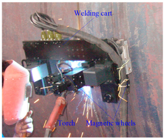
Figure 6.
Mobile welding robot prototype with magnetic wheels.

Table 1.
Parameters of mobile welding robot with magnetic wheels.
Table 2.
Welding experiment parameters for mobile welding robot with magnetic wheels.
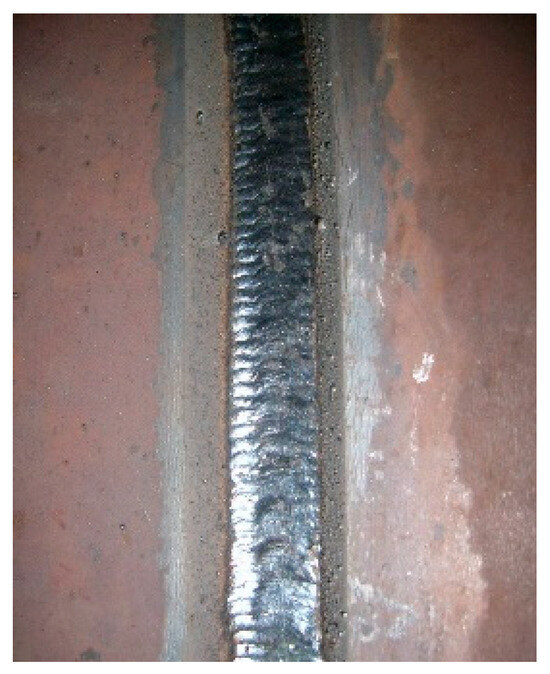
Figure 7.
The post-welding test weld seam.
- 2.
- Rail-mounted mobile welding robot
For the requirement for all-position automatic welding of carbon steel air-conditioning pipelines with relatively small-surface curvature radii (Rc = 305 mm), according to the configuration design process for wheeled mobile welding robots under multiple working conditions, when k = 2, the configuration of the rail-mounted mobile welding robot based on small wheels should be selected. The physical prototype was designed and manufactured, as shown in Figure 8. The parameters of rail-mounted wheeled mobile welding robot are shown in Table 3. A guiding track is installed on the pipeline to be welded. The wheeled mobile welding cart carrying the welding torch component moves on the track. Moving along the pipeline for one circle can complete the all-position automatic welding operation of the entire pipeline. The welding experiment parameters are shown in Table 4, and the process test weld seam after welding is shown in Figure 9. The welding test shows that the robot runs stably, the weld seam formation is uniform, and the welding quality is high, thus verifying the effectiveness of the configuration design scheme of the rail-mounted mobile welding robot based on small wheels.
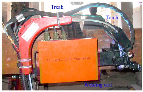
Figure 8.
Rail-mounted wheeled mobile welding robot.
Table 3.
Parameters of rail-mounted mobile welding robot.
Table 4.
Welding experiment parameters of rail-mounted mobile welding robot.
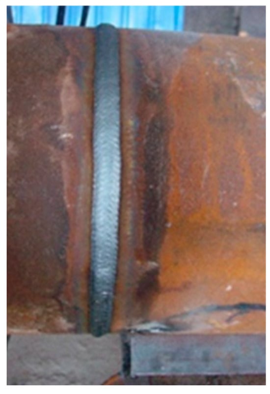
Figure 9.
Process test weld seam after welding.
- 3.
- Flexible contour tracing mobile welding robot
During the manufacturing process of the turbine guide ring, a layer of stainless steel needs to be surface-welded on its surface to delay corrosion and prolong its service life. As shown in Figure 10, the cross-section of the surface to be welded on the guide vane ring is α-shaped, with the narrowest opening being less than 160 mm and the minimum curvature radius being approximately 50 mm. Conventional wheeled mobile welding robots and rail-mounted mobile welding robots are unable to enter the inner α-shaped surface of the guide vane ring for welding operations. According to the configuration design process of wheeled mobile welding robots under multiple working conditions, the configuration of the flexible contour tracing mobile welding robot based on micro wheels, when k = 3, should be selected. The physical prototype was designed and manufactured according to this configuration, as shown in Figure 11.
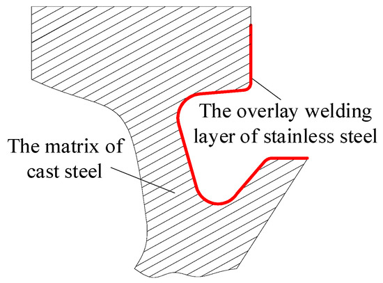
Figure 10.
Cross-section of the guide ring.
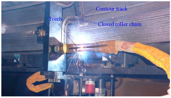
Figure 11.
Flexible contour tracing mobile welding robot.
The parameters of flexible contour tracing mobile welding robot are shown in Table 5. Considering economic applicability and practical engineering applications, a closed roller chain is used instead of the micro wheeled welding carts connected head-to-tail. A contour track matching the surface profile of the workpiece to be welded is used to constrain it, and the transmission chain carries a specially made micro welding torch to perform surfacing welding on the surface of the guide ring. The surfacing welding test parameters are shown in Table 6. The welding experiment demonstrates that the application of this mobile welding robot has increased welding efficiency by three times. The weld seam formation effect is shown in Figure 12. The weld seam is uniform and well-formed, verifying the effectiveness of the configuration design scheme for the flexible contour-type mobile welding robot based on micro wheels.
Table 5.
Parameters of flexible contour tracing mobile welding robot.
Table 6.
Welding experiment parameters of flexible contour tracing mobile welding robot.
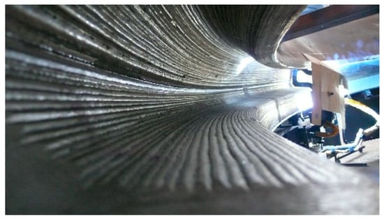
Figure 12.
Surfacing weld seams for turbine guide ring.
In conclusion, based on the practical engineering requirements associated with three typical working conditions, which are distinguished by the curvature radius values of the welding robot’s traveling path, three corresponding prototypes of wheeled mobile welding robots were designed and manufactured according to a configuration design process tailored for multiple working conditions. Welding experiments were then conducted to assess their performance. The experimental results demonstrate that all three types of wheeled mobile welding robots can stably perform automatic welding operations, producing well-formed weld seams and achieving high welding quality. This verifies the effectiveness of the configuration design schemes for wheeled mobile welding robots under these three typical working conditions.
5. Discussion
This paper, taking the curvature radius of the travel path of a mobile welding robot as a clue, constructs the Lagrange’s equations of the mobile welding robot on arbitrary paths. Through numerical simulation analysis based on simplifying and deriving these equations with practical engineering experience, it is concluded that for relatively flat paths with larger curvature radii, a wheeled mobile welding robot structure with a relatively larger volume is suitable, while for complex road conditions that are not flat, i.e., paths with smaller curvature radii, a wheeled mobile welding robot structure with a relatively small volume is more appropriate. Combining the above analysis and considering the robot’s own load-bearing characteristics, a configuration design concept for wheeled mobile welding robots is ultimately formed. This concept evolves from large wheels to small wheels and then to micro wheels, incorporating track constraints and increasing the number of wheels. Subsequently, based on three typical welding conditions, we construct an implicit configuration design function for wheeled mobile welding robots. This is a piecewise function comprising three parts, each representing a robot configuration distinct from the others. We also present the different welding condition environments suitable for each wheeled mobile welding robot configuration. Finally, based on the engineering application requirements of the three typical condition environments, corresponding robot prototypes are manufactured and welding experiments are conducted. The experimental results are satisfactory, thus verifying the effectiveness of the configuration design method proposed in this paper.
Previously, all research on mobile welding robots was conducted for specific welding scenarios and was only applicable to current conventional working conditions, mainly consisting of conventional wheeled mobile welding robots and wheeled mobile welding robots with track constraints. This paper not only proposes a flexible contour tracing mobile welding robot based on micro wheels for automatic welding operations in confined spaces but also presents a configuration design methodology for wheeled mobile welding robots that is more versatile and applicable under various welding conditions. This method can provide a valuable reference for the structural design of wheeled mobile welding robots in complex, unknown, and unstructured conditions. Such a design concept and robot configuration design methodology were previously non-existent.
Although the wheeled mobile welding robot proposed in this paper for use in confined spaces can be applied in practical engineering, its torch adjustment mechanism requires manual adjustment, and thus the level of automation still needs to be further improved. Conventional automatic torch adjustment mechanisms are too large to be installed in corresponding limited spaces. Enhancing the automation level of the flexible contour tracing mobile welding robot based on micro wheels will be a research focus in the near future. Research on micro torch automatic adjustment mechanisms suitable for confined spaces has been included in our research plan. It is believed that in the near future, the automation and intelligence level of the flexible contour tracing mobile welding robot based on micro wheels will be further improved.
6. Conclusions
This paper proposes to characterize the welding operational conditions of a mobile welding robot by the curvature radius of its travel path. Lagrange’s equation is formulated to model the motion of a wheeled mobile welding robot on an arbitrary path, which is then simplified and analyzed based on practical engineering experience. Numerical simulation analysis reveals that welding paths with larger curvature radii are suitable for wheeled mobile welding robots with larger wheels, while those with smaller curvature radii are better suited for robots with smaller wheels. Combining these with the robot’s load-bearing capacity, a design concept for the wheeled mobile welding robot configuration is developed, with the design concept evolving from large wheels to small wheels to micro wheels, complemented by track constraints and an increase in the number of wheels. An implicit configuration design function for wheeled mobile welding robots under multiple conditions is constructed, and a configuration design process is proposed, providing a reference for the configuration design of wheeled mobile welding robots in complex and unknown working environments. Based on the engineering requirements for automatic welding in three typical operational environments, physical prototypes are manufactured and subjected to welding experiments. The experimental results validate the effectiveness and practicality of each wheeled mobile welding robot, further confirming the efficacy of the proposed configuration design methodology of wheeled mobile welding robots.
Author Contributions
Conceptualization, methodology, S.Y., L.X., J.H. and Y.Z.; software, S.Y. and R.Z.; funding acquisition, L.X. and J.H.; validation, formal analysis, investigation, resources, data curation, S.Y., L.X. and J.H.; writing—original draft preparation, S.Y. and J.H.; writing—review and editing, S.Y., Y.Z. and R.Z. All authors have read and agreed to the published version of the manuscript.
Funding
This work was supported by the National Key Research and Development Program of China (2023YFB3407700).
Data Availability Statement
Data are contained within the article.
Conflicts of Interest
The authors declare no conflicts of interest.
References
- Kam, B.O.; Jeon, Y.B.; Kim, S.B. Motion Control of Two-Wheeled Welding Mobile Robot with Seam Tracking Sensor. In Proceedings of the IEEE International Symposium on Industrial Electronics, Pusan, Republic of Korea, 12–16 June 2001; Volume 2, pp. 851–856. [Google Scholar] [CrossRef]
- Chen, S.F.; Liu, J.; Chen, B.; Suo, X.Y. Universal Fillet Weld Joint Recognition and Positioning for Robot Welding Using Structured Light. Robot. Comput. Integr. Manuf. 2022, 74, 102279. [Google Scholar] [CrossRef]
- Tang, Q. Localization and Tracking Control for Mobile Welding Robot. Ind. Robot. 2014, 41, 259–265. [Google Scholar] [CrossRef]
- Warnecke, H.-J.; Gzik, H.; Utner, W. From the Industrial Robot Welding Cell to the Industrial Robot Welding System. Int. J. Adv. Manuf. Technol. 1986, 1, 25–38. [Google Scholar] [CrossRef]
- Yuan, J.Z.; Han, H.A.; Liu, Y.G.; Wang, Z.X.; Zheng, C. Mobile collaborative welding system for complex welding seams. Procedia CIRP 2022, 107, 1520–1525. [Google Scholar] [CrossRef]
- Ogbemhe, J.; Mpofu, K. Towards Achieving a Fully Intelligent Robotic Arc Welding: A Review. Ind. Robot. 2015, 42, 475–484. [Google Scholar] [CrossRef]
- Dung, N.M.; Duy, V.H.; Phuong, N.T.; Kim, S.B.; Oh, M.S. Two-Wheeled Welding Mobile Robot for Tracking a Smooth Curved Welding Path Using Adaptive Sliding-Mode Control Technique. Int. J. Control Autom. 2007, 5, 283–294. [Google Scholar] [CrossRef]
- Tom, N.; Badam, D.K.; Kumar, V.R.; Lakshmi, V. Design and Implementation of Mobile Robotic Manipulator for Welding Using PLC. Sens. Transducers 2015, 188, 96–101. Available online: https://api.semanticscholar.org/CorpusID:52101890 (accessed on 10 February 2025).
- Cui, S.; Song, H.; Zheng, T.; Dai, P. Trajectory Tracking Control of Mobile Manipulator Based on Improved Sliding Mode Control Algorithm. Processes 2024, 12, 881. [Google Scholar] [CrossRef]
- Dharmawan, A.G.; Vibhute, A.A.; Foong, S.; Soh, G.S.; Otto, K. A Survey of Platform Designs for Portable Robotic Welding in Large Scale Structures. In Proceedings of the 2014 13th International Conference on Control, Automation, Robotics & Vision (ICARCV), Singapore,, 10–12 December 2014; pp. 1683–1688. [Google Scholar] [CrossRef]
- Yao, S.; Xue, L.; Huang, J.; Chen, B.; Zhang, R.; Han, F. Research and Experiment on a Mobile Welding Robot for Expandable Convoluted Pipe. Sci. Rep. 2025, 15, 8219. [Google Scholar] [CrossRef]
- Choi, T.; Park, J.; Bak, J.; Park, D.; Seo, H.; Kim, S. The Developmentof Software to Automate the Laser Welding of a Liquefied Natural Gas Cargo Tank Using a Mobile Manipulator. Appl. Sci. 2024, 14, 134. [Google Scholar] [CrossRef]
- Suga, Y.; Muto, A.; Kumagai, M. Automatic Tracking of Welding Line by Autonomous Mobile Robot for Welding of Plates. Tracking of Linear and Angled Welding Lines. Trans. Jpn. Soc. Mech. Eng. Ser. C 1997, 63, 2918–2924. [Google Scholar] [CrossRef][Green Version]
- Ngo, M.D.; Phuong, N.T.; Duy, V.H.; Kim, H.K.; Kim, S.B. Control of Two Wheeled Welding Mobile Manipulator. Int. J. Adv. Robot. Syst. 2007, 4, 293–302. [Google Scholar] [CrossRef]
- Lyu, X.Q.; Zhang, K.; Wu, M. The Seam Position Detection and Tracking for the Mobile Welding Robot. Int. J. Adv. Manuf. Technol. 2016, 88, 2201–2210. [Google Scholar] [CrossRef]
- Shang, J.; Bridge, B.; Sattar, T.; Mondal, S.; Brenner, A. Development of a Climbing Robot for Inspection of Long Weld Lines. Ind. Robot. 2008, 35, 217–223. [Google Scholar] [CrossRef]
- Liu, W.; Li, Q.; Yue, J.; Zhu, P.; Li, B. Research Status and Progress of All-Position Narrow-Gap GMAW for Pipelines. Appl. Sci. 2025, 15, 2270. [Google Scholar] [CrossRef]
- Zhang, T.; Chen, S.B.; Wu, M.H.; Zhao, Y.Z.; Chen, X.Q. Optimal Motion Planning of All Position Autonomous Mobile Welding Robot System for Fillet Seams. IEEE Trans. Autom. Sci. Eng. 2013, 4, 1147–1151. [Google Scholar] [CrossRef]
- Liao, B.; Shi, Y.; Cui, Y.; Cui, S.; Jiang, Z.; Yi, Y. Mathematical Model for Prediction and Optimization of Weld Bead Geometry in All-Position Automatic Welding of Pipes. Metals 2018, 8, 756. [Google Scholar] [CrossRef]
- Suga, Y.; Saito, K.; Sano, T. Recognition and Automatic Tracking of Weld Line in Welding of T-Joint of Pipes by an Autonomous Mobile Robot with Vision Sensor. Trans. Jpn. Soc. Mech. Eng. 1996, 62, 1191–1196. [Google Scholar] [CrossRef]
- Ang, M.H.; Lin, W.; Lim, S. A Walk-Through Programmed Robot for Welding in Shipyards. Ind. Robot. An. Int. J. 1999, 26, 377–388. [Google Scholar] [CrossRef]
- Yao, S.Y.; Xue, L.; Huang, J.Q.; Zhang, R.Y. Design Methodology of a Flexible Contour Tracing Mobile Welding Robot for Complex Surface Welds. In Proceedings of the 5th International Conference on Mechatronics Technology and Intelligent Manufacturing, Nanjing, China, 26–28 April 2024; pp. 569–574. [Google Scholar] [CrossRef]
- Sun, E.; Camacho-Arreguin, J.; Zhou, J.F.; Liebenschutz-Jones, M.; Zeng, T.; Keedwell, M.; Axinte, D.; Norton, A.; Mohammad, A. Macro-mini Collaborative Manipulator System for Welding in Confined Environments. Robotics Comput.-Integr. Manuf. 2025, 94, 102975. [Google Scholar] [CrossRef]
- Zheng, L.; Ji, A.H.; Cheng, Y.; Qin, G.D.; Zhang, W.J.; Zhang, Y.; Wang, C.; Han, H. Design and Development of Automatic Pipe Cutting and Welding Robot for Fusion Reactor. Fusion. Eng. Des. 2024, 205, 114555. [Google Scholar] [CrossRef]
- Jiang, Y.; Han, Q.Q.; Dai, Z.E.; Zhou, C.; Yu, J.F.; Hua, C.J. Structural Design and Kinematic Analysis of a Welding Robot for Liquefied Natural Gas Membrane Tank Automatic Welding. Int. J. Adv. Manuf. Technol. 2022, 122, 461–474. [Google Scholar] [CrossRef]
- Bu, H.; Cui, X.; Huang, B.; Peng, S.; Wan, J. Research Review and Future Directions of Key Technologies for Welding Robots in the Construction Industry. Buildings 2024, 14, 2261. [Google Scholar] [CrossRef]
- Xue, L.; Zou, Y.; Huang, J.Q.; Huang, J.F.; Tao, X.H.; Hu, Y.F. Constant Speed Control for Complex Cross-section Welding Using Robot Based on Angle Self-Test. Chin. J. Mech. Eng. 2014, 27, 260–268. [Google Scholar] [CrossRef]
- Yu, S.F.; Guan, Y.S.; Yang, Z.; Liu, C.T.; Hu, J.C.; Hong, J.; Zhu, H. Multiseam Tracking with a Portable Robotic Welding System in Unstructured Environments. Int. J. Adv. Manuf. Technol. 2022, 122, 2077–2094. [Google Scholar] [CrossRef]
- Bu, Y.; Dun, L.; Deng, Y.; Jiang, B.; Jiang, A.; Zhu, H. Development of a Bicycle-like Magnetic-Wheeled Climbing Robot with Adaptive Plane-Transition Capabilities. Machines 2025, 13, 167. [Google Scholar] [CrossRef]
- Pérez-Juárez, J.G.; García-Martínez, J.R.; Medina Santiago, A.; Cruz-Miguel, E.E.; Olmedo-García, L.F.; Barra-Vázquez, O.A.; Rojas-Hernández, M.A. Kinematic Fuzzy Logic-Based Controller for Trajectory Tracking of Wheeled Mobile Robots in Virtual Environments. Symmetry 2025, 17, 301. [Google Scholar] [CrossRef]
- Cossette, C.C.; Forbes, J.R.; Saussié, D. Lagrangian Derivation of Variable-Mass Equations of Motion using an Arbitrary Attitude Parameterization. J. Astronaut. Sci. 2020, 67, 1206–1219. [Google Scholar] [CrossRef]
- Erik, C. Classical Mechanics Is Lagrangian; It Is Not Hamiltonian. Brit. J. Philos. Sci. 2013, 65, 269–321. [Google Scholar] [CrossRef]


Disclaimer/Publisher’s Note: The statements, opinions and data contained in all publications are solely those of the individual author(s) and contributor(s) and not of MDPI and/or the editor(s). MDPI and/or the editor(s) disclaim responsibility for any injury to people or property resulting from any ideas, methods, instructions or products referred to in the content. |
© 2025 by the authors. Licensee MDPI, Basel, Switzerland. This article is an open access article distributed under the terms and conditions of the Creative Commons Attribution (CC BY) license (https://creativecommons.org/licenses/by/4.0/).