Article

Friction Monitoring in Kaplan Turbines

1
Machine Elements, Department of Engineering Sciences and Mathematics, Luleå University of Technology, 971 87 Luleå, Sweden
2
Fortum Sverige AB, 115 77 Stockholm, Sweden
*
Author to whom correspondence should be addressed.
Machines 2025, 13(4), 313; https://doi.org/10.3390/machines13040313
Submission received: 17 March 2025 / Revised: 4 April 2025 / Accepted: 7 April 2025 / Published: 11 April 2025
(This article belongs to the Special Issue Vibration-Based Machines Wear Monitoring and Prediction)

Abstract

Hydropower is important in the modern power system due to its ability to quickly adjust production. More frequent use of this ability may lead to increased maintenance needs, highlighting the importance of research in condition monitoring for hydropower. This study suggests a model approach for friction monitoring of the bearings inside the Kaplan turbine’s hub. The approach is developed for when normal and anomalous data exist. The study compares isolation forest (iForest), local outlier factor (LOF), one-class support vector machine (OC-SVM), and Mahalanobis distance (MD) for anomaly detection, where iForest and OC-SVM appear to be good choices due to their robust performance. A moving decision filter (MDF) is fed with the output from the anomaly detection models to classify the data as normal or anomalous. The parameters in the MDF are optimized with Bayesian optimization to increase the performance of the models. The approach is tested using data from two actual hydropower turbines. The study shows that the model approach works for both turbines. However, the parameter optimization must be performed separately for each turbine.
Key Contribution: Method for friction monitoring in Kaplan turbines.

1. Introduction

Hydropower is the largest renewable electricity source in the world today. The hydropower fleet is considered quite old, where about 40% of the global fleet is 40 years old or older [1]. The increasing installation of solar power and wind power capacity is creating new challenges for the hydropower fleet. One is intermittency, which makes the produced power output dependent on meteorological conditions [2]. Some of this intermittency can be taken up by hydropower production [3]. Therefore, balancing electricity sources such as hydropower will become more critical in the future [4]. Consequently, hydropower’s ability to ramp production up and down will likely be utilized more frequently. The impact on the plant’s service life is currently unknown, but it may lead to increased maintenance efforts.
Kaplan turbines are often used in low-head hydropower applications and have adjustable runner blades, which allow for high efficiency across a wide operating range. According to the industry, some Kaplan turbines have suffered from increasing friction in their runner blade bearings located in the Kaplan hub. Some increase in friction may occur during the turbine’s lifespan without being considered to be a problem. However, there are more worrying scenarios in which the industry has installed new bearings in the turbines and the friction has increased severely over only a few years. These faults have been connected to water-lubricated bearings and are most likely connected to the design of the bearing. Eventually, this can lead to such high friction forces that the hydraulic regulation system cannot move the runner blades. This can lead to problems such that the producers can only run the turbines at fixed power outputs, which affects the flexibility and may cause a loss in revenue. To change or fix issues with the bearings, the whole runner must be lifted out of the plant, which is an expensive and time-consuming task that requires extensive planning. The industry, therefore, wants early detection of changes in friction behavior to enable better operation of the turbine to extend runner blade bearings’ service life and better planning of maintenance so it can be performed when the electricity demands are low. Today, it is rare to have sensors close to these bearings that could be used to monitor changing friction levels. Methods that could detect anomalous friction levels in these bearings from other already monitored features are, therefore, of great interest to the industry, which is why research on condition monitoring (CM) models aiming to detect anomalous friction levels in these bearings is essential.
CM and condition-based maintenance (CBM) are used to assess and predict the health of a machine. The associated costs are often justified by decreased downtime and maintenance [5]. However, it is usually impossible to monitor everything due to high costs. Condition-based maintenance can be preferable when replacement costs are high [6], there are no clear time intervals for failures, and failures are correlated to measurable features [7]. Hydropower fits quite well into these criteria.
Currently, data from hydropower are often collected by a supervisory control and data acquisition (SCADA) system. Obtaining datasets with labeled faults is challenging, which is why much of the research on CM in hydropower focuses on anomaly detection, which more or less attempts to compare similar new instances to the model’s training data.
Zhu et al. developed a kernel independent component analysis and principal component analysis (KICA-PCA) model incorporating process parameters and vibration signals. The kernel independent component analysis (KICA) transforms the signals into a higher linearly separable space, and principal component analysis (PCA) is used to pick out the most essential individual components. Hotelling T2 statistics and squared prediction error (SPE) are utilized to set a threshold based on normal or healthy training data. By comparing the statistics from new instances and examining if they are above the established threshold, anomalies can be detected [8].
Betti et al. used a self-organizing map (SOM) to develop a key performance indicator (KPI) that compares new instances to historical data to detect anomalies. Anomalies are identified by setting a threshold value on the KPI [9].
Furthermore, de Andrade Melani et al. suggested a hybrid system using moving window PCA for fault detection and a Bayesian network to identify specific faults. They first cluster the sensors into different fault groups, and moving window PCA is conducted on each cluster of signals. Logical values are obtained from the PCA signals from each cluster that indicate if any changes are occurring. Then, the Bayesian network indicates which cluster of signals the fault will most likely come from [10].
Remaining useful life (RUL) models can often be complex to implement in hydropower since RUL models are typically based on data covering the entire life of a machine. Each turbine is often built for a specific location in hydropower, making them more or less unique. Moreover, large parts of the fleet were built between the 1960s and the 1980s [1] before the SCADA systems were implemented. Because significant failures are rare, data to build ordinary RUL models are hard to obtain. A health index can be another approach to predict the machine’s behavior in the future. Jiang et al. built a composite health index using an autoencoder and an SOM network, which estimates how similar new instances are compared to the training data for the model. Long short-term memory (LSTM) was then used to predict the trend of the health index regarding future instances [11]. This type of model can be one way to plan for maintenance without having the same amount of data that an RUL model would require.
Ahmed et al. developed a model that contains two minimum spanning trees. One global tree divides the data into clusters, which can indicate if any clusters deviate from the rest of the data. A local minimum spanning tree is also held inside each cluster to look for outliers. They can later train a classification tree from the detected outliers to detect similar faults in the data. When trained on data from a hydropower plant, a detected fault can be connected to a bearing [12].
Pino et al. used vibration data from the startup of a turbine to develop a hidden Markov model to detect guide bearing degradation [13].
Bütüner et al. used machine learning to predict the pressure to move the guide bearing from other process and hydraulic parameters in the SCADA system. Here, random forest provided the best results [14].
Wang et al. used the reconstruction loss from an autoencoder that is fed with water flow and oil levels to detect inadequate lubrication of the generator guide bearing [15].
Åsnes et al. used a one-class support vector machine model to detect high friction in the guide vane bearings by feeding the model the differential pressure and the guide vane position [16]. This will yield only a yes or no value, which is easy for the operator to interpret. Detecting changing friction is a problem that the industry is currently looking into. However, to really evaluate the performance of friction monitoring models, a degraded system would need to be tested. This would provide insight into how sensitive the models are and need to be.
This study uses anomaly detection to develop a method for detecting anomalous friction levels in the bearings inside the hubs of Kaplan turbines. It uses operational data from two actual Kaplan turbines, each containing periods of both normal and anomalous friction conditions. Different machine-learning models and other modeling decisions have been evaluated to see how they impact the detection of anomalous friction levels inside the Kaplan runner. In more detail, the study investigates the impact of feature selection, pre-filtering of data, model selection, and the moving decision filter (MDF) impact on the final models. Metrics for model selection are also investigated as they are crucial, especially when working with a limited amount of data. Hopefully, this can help the industry to detect changed friction behaviors earlier and, therefore, be used for operation and maintenance planning.

2. Methods

The Kaplan turbine is a standard low-head turbine that can move its runner blades to achieve better efficiency for varying flows and heads. An illustration of an installed Kaplan turbine is shown in Figure 1a. Bearings inside the turbine’s hub enable the runner blades to move and absorb the loads created by the water flow; see Figure 1b. Here, the force from the water flow, F WL , is taken up by the bearings in N B 1 and N B 2 . The normal forces on the bearings are connected to the friction force F B in Figure 1c as
F B = μ B N B = μ B 1 N B 1 + μ B 2 N B 2
where μ B is the coefficient of friction. To regulate the runner blades, the hydraulic system needs to overcome the friction force F B and the torque T WL from the water load. The torque T WL can also work in favor of the hydraulic system, depending on the point of operation and regulation direction. Changing friction coefficients will, however, affect the torque needed to regulate the system.
An increased coefficient of friction would result in a larger torque needed to move the runner blades. The torque is transferred to the runner blades by a hydraulic cylinder that is connected to all the runner blades by an internal linkage. A common way to monitor changing friction levels is the differential pressure p diff , which is defined as
p diff = p close p open
where p close and p open correspond to the pressures on the hydraulic cylinder’s different sides. Natural variations in the differential pressure are connected to the power output, head, water temperature, design, power regulation, and more. The unwanted changes in the differential pressure would instead come from slow changes over time that more or less increase the overall pressure and forces required to move the runner blades.
In some cases, the industry has observed increasing differential pressures over time. To address this, glycerol is injected into the hub as a lubricant for all exposed bearings, which are otherwise water-lubricated or dry. This reduces the friction coefficient in the system and lowers the overall differential pressure. In addition to the bearings shown in Figure 1b, there are bearings that support the axial loads on the runner blades and bearings connected to the linkage inside the hub, which enables the movement of the runner blades. The injection of glycerol will also lubricate these bearings, thereby contributing to the decrease in differential pressure. Monitoring will be important to see how long this reduction in friction will last.
From a model perspective, injecting glycerol into the system instantly impacts the friction coefficient, allowing the data to be labeled anomalous or normal before and after the injection.

2.1. Data Acquisition

The data acquisition in this work comes from two different Kaplan turbines. The sample frequency is one sample per minute, and each feature has an average, minimum, and maximum value during each minute. The datasets are labeled according to glycerol’s presence in the Kaplan turbine’s hub during operation. In the datasets, p close and p open represent the pressures on the different sides of the hydraulic cylinder, t oil is the temperature of the hydraulic oil, and p sys is the system pressure in the hydraulic system. The subscripts Avg, Min, and Max denote if the value is an average, minimum, or maximum value during one minute of sampling as the original sample frequency from the SCADA system is higher than 1 sample per minute. Table 1 summarizes the information on the different datasets.

2.2. Training, Validation, and Test Sets

The data are divided into training, validation, and test sets. The division occurs by splitting the data into specific time intervals. The first 50% of the data points is the training set, the validation set consists of the next 20%, and the test set comprises the last 30% of the points. In this way, the original order of the data points is kept, making the validation and test sets come later in time than the training sets, which hopefully will better resemble the use in the actual application. The data are divided into two parts: one without glycerol in the system, labeled as anomalous, and one where glycerol is present, labeled as normal. The anomalous and normal classes were handled separately when dividing the data, as stated above. To exemplify, this means that 50% of the anomalous and 50% of the normal data are put in the training set.
The data from both turbines are skewed as they contain more anomalous than normal data. To resolve this, all numeric results and optimizations are performed without the last points in the time series of each set of anomalous data. If nothing else is stated, the number of data points for the anomalous and normal data will be the same in evaluations regarding the performance of the models.

2.3. Features

To identify which features are the most important for anomaly detection, the features are divided into six feature sets, as seen in Table 2. The idea of feature sets E and F is to take all available features from the data; therefore, the differential p diff is not included in these feature sets. Training all the models with all the feature sets provides insight into how the choice in features affects the anomaly detection performance.

2.4. Pre-Filtering

When the runner blades on the Kaplan turbine are regulated to fully closed, a mechanical stop will be reached, and the hydraulic pressures will then reach the maximum for which the system is designed. Therefore, these pressures occur during normal conditions, and the data are filtered to remove them as they may look like anomalous instances. The filtering is conducted by considering the average signals for the closing and opening pressures, and outliers are detected by considering the scaled median absolute deviation (MAD) defined as
scaled MAD = c × median | X i median ( X ) | , for i = 1 , 2 , , N
where X is a feature vector with N number of samples and c = 1.4826 . The scaled MAD is calculated for both the closing and opening pressure, and outliers are defined as values that are more than three times the scaled MAD from the median. If an outlier is detected in one of the pressures, all features from that timestamp will be replaced by the previous non-outlier value from the data.

2.5. Normalization

Normalization is conducted using the z-score. For the data X with a mean μ and standard deviation σ , the z-score is
z = x μ σ
for single values of x. The training and validation sets are normalized together, and the test set is normalized separately using the same mean and standard deviation from the training and validation sets.

2.6. Models

In the actual application, the models aim to detect anomalies connected to the required forces to move the runner blades. They are trained on “healthy” or normal data, considered when glycerol is present in the system. This applies to all models tested. Below is a brief explanation of the models tested in this study. The choice in models is based on their simplicity in implementation, which facilitates the implementation in real hydropower plants.
For clarity, positive predictions refer to instances predicted as anomalous, and negative predictions refer to instances predicted as normal.

2.6.1. Isolation Forest (iForest)

The isolation forest (iForest) algorithm is an ensemble of many isolation trees (iTrees), a tree model that isolates anomalies rather than profiles normal instances. Each tree has a split variable and a split position chosen at random. The tree grows until each sample has a separate leaf node. The anomaly score is then calculated by the path length where anomalies are detected near the tree’s root as they are easier to separate from the rest of the data. More information about iForest can be found in [17]. The number of trees was set to 100, and the number of observations per tree was set to min ( N , 256 ) , where N is the number of observations.

2.6.2. Local Outlier Factor (LOF)

Local outlier factor (LOF) examines the density of points relative to surrounding neighbors. Anomalies are detected by low density, indicating greater distance to surrounding points. More information about LOF can be found in [18]. The number of neighbors is set to min ( 20 , n 1 ) , where n is the number of unique rows in the predictor data.

2.6.3. One-Class Support Vector Machine (OC-SVM)

One-class support vector machine is a form of unsupervised SVM, which is a kernel-based method that separates anomalies by constructing a hyperplane in a high-dimensional feature space. Points far away from the hyperplane are then considered anomalies. More about one-class support vector machine can be found in [19]. The model uses the Gaussian kernel with a kernel scale of 1.

2.6.4. Mahalanobis Distance (MD)

Mahalanobis distance examines the distance between a sample point and a sample distribution by considering the mean and covariance of the distribution. The models tested here use the robust Mahalanobis distance.

2.7. Moving Decision Filter (MDF)

A moving decision filter is applied to the models’ anomaly scores to avoid alarms for singular anomalies in the data. The MDF is defined by two parameters: the window size and a threshold. The window size indicates how many data points should be considered in each decision. If all points in a window are greater than the predefined threshold, all points are deemed anomalous in that window. The window moves one step at a time.
Due to the many combinations of window sizes and thresholds that exist, Bayesian optimization is performed for each model and dataset to find the best combination. Bayesian optimization was chosen to reduce the number of iterations. Another benefit compared to other strategies, such as grid search, is that only the examination range for the variables needs to be defined, not the grid size. The models aim to classify the points with glycerol in the system as normal and points without glycerol as anomalous. The optimization is achieved by obtaining the highest F 1 
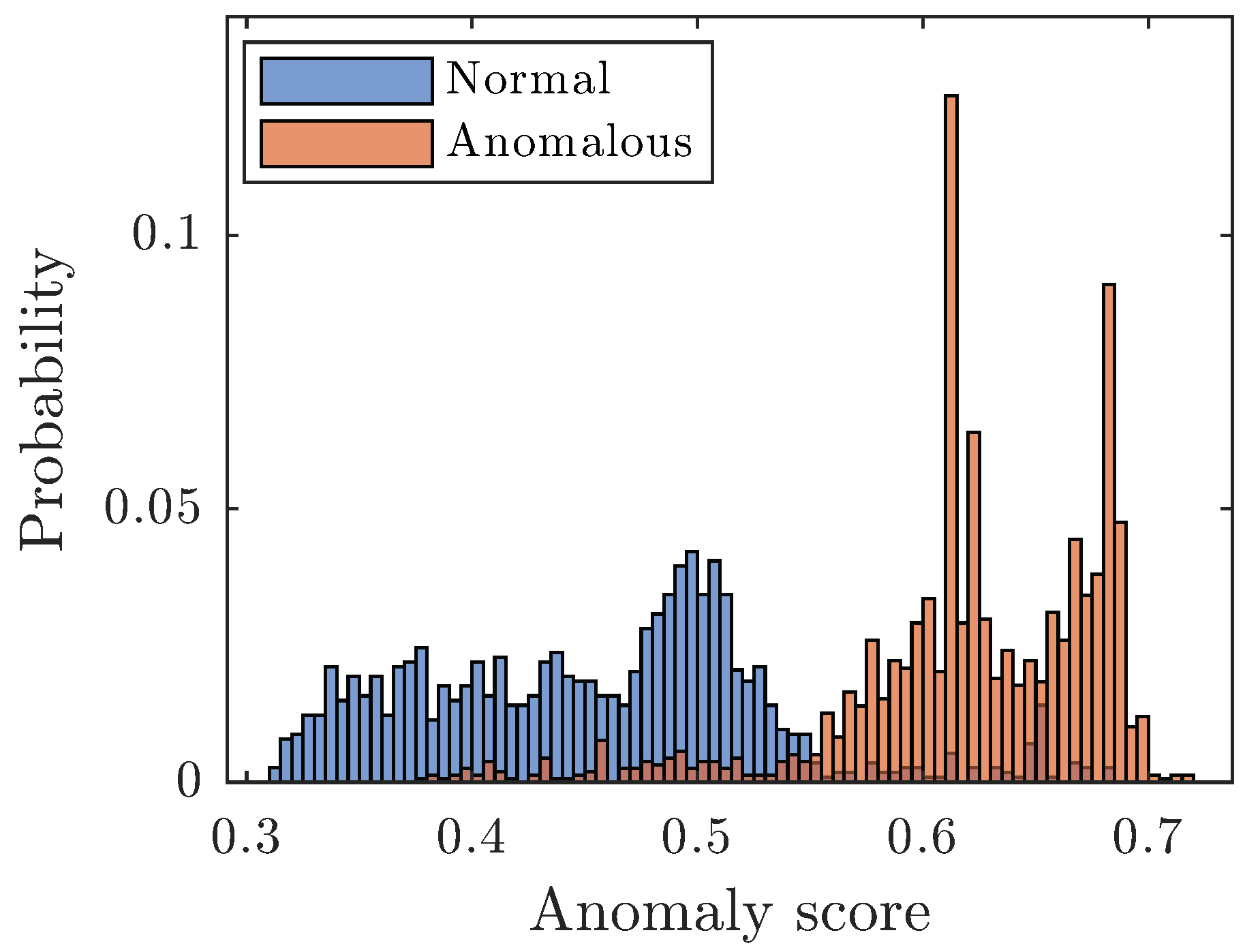
score on the validation set. The window size range is set to 1–4320, which corresponds to a time range of 1 min up to 3 days. The range of the thresholds is set individually for each model by inspecting the histograms for anomaly scores on the training and validation sets. The threshold range is then set to ensure that the best threshold will be included. As an example, Figure 2 shows the anomaly scores for the normal and anomalous data for iForest, and here the range for the thresholds was set to 0.3–0.7. The maximum number of iterations is set to 200, but some models have overridden that with a few iterations due to parallel computing.

3. Results and Discussion

This section shows the effects of the different modeling decisions and their impact on the models. The best-performing models have been used as a reference to see how individual choices affect the overall performance.

3.1. Optimizing Moving Decision Filter (MDF)

The optimal window size and threshold, according to Bayesian optimization, are presented in Table 3, and the corresponding performance of each model is presented in Table 4. The F 1 scores for all the models are also visually presented in Figure 3.

Influence of Threshold and Window Size on MDF

The best-performing models on the test set are further analyzed to see how the various thresholds and window sizes influence performance during Bayesian optimization. Figure 4 shows how the range of thresholds used in Bayesian optimization influences the F 1 score on the validation set. At the same time, the window size is held constant at the best window size for that model according to Table 3. Because the threshold range varies between models, no units are on the x-axis. The same procedure is performed for the range of window sizes while the thresholds are held constant; see Figure 5. The range is divided into 100 steps to calculate the F 1 score.
The threshold influences the F 1 score here more than the window size on the investigated range. For the threshold on Turbine 2 for one-class support vector machines, there is more of a plateau for the best score, and the choice is not as critical. These plateaus are more common for the iteration over the window sizes, showing that a range of window sizes will provide the same result. The range for the window sizes was set to a maximum of three days, which seems beneficial for one-class support vector machines and Mahalanobis distance regarding Turbine 2.
Figure 4 and Figure 5 show that the Bayesian optimization effectively finds the best threshold and window size for the MDF. As these iterations were conducted with a resolution of 100 elements for the threshold and the window size, slightly better optimal points could be found; on average, the difference is less than 1%. A grid search with this resolution would yield 100 × 100 calculations compared to Bayesian optimization, which was set to 200 calculations. There is no need to define a grid for the Bayesian optimization either, which speaks to its favor.
This optimization was conducted using normal and anomalous data. Access to anomalous data is, in many cases, not possible. The threshold could be set from guidance by the anomaly score histograms as in Figure 2, but there is no clear way to establish the window size. As seen from Figure 4 and Figure 5, the optimum depends on both the model and turbine.

3.2. Impact of Feature Set

In Figure 3, the F 1 scores on the test set for all the MDF models can be studied. The best-performing feature sets across all the models are F for Turbine 1 and B for Turbine 2. The only difference in feature sets between the turbines is that Turbine 1 has the oil temperature, whereas Turbine 2 has the system pressure. As for Turbine 1, the best-performing models are found in feature sets E and F, where the oil temperature is present. Whereas, for Turbine 2, the best-performing models were found in feature sets A, B, and E. Here, one-class support vector machine was the only model that gained performance from feature set E, which also included the system pressure. None of the best-performing models were found in feature sets C and D; the models, therefore, seem to prefer the individual pressure signals over the differential pressure.

3.3. Impact of Pre-Filter

The results presented so far were with the pre-filter. On average, the F 1 scores on the test set for all the models in Table 4 are improved by 12% for Turbine 1 and 11% for Turbine 2. Figure 6 shows the impact of the pre-filter on the F 1 scores for the best-performing models on the test set. No clear pattern of which model benefits the most from the pre-filter is shown here. But, the negative effect is more significant for iForest, so pre-filtering may be excluded from these models.

3.4. Impact of Models

The best-performing models of each type are shown in Figure 7 and Figure 8 for Turbine 1 and Turbine 2, respectively. The data are plotted against the average differential pressure, p diffAvg , since applying a threshold on this feature is one simple way to monitor increasing friction. The red line (A/N), which separates the anomalous and normal data, is located at the timestamp where glycerol was added to the system.
For Turbine 1, one-class support vector machine and Mahalanobis distance had the best F 1 scores on the test set, with less than a 1% difference between them. However, the high F 1 scores come from higher precision for one-class support vector machine, while the Mahalanobis distance achieves it from higher recall; see Table 4. When comparing the models in Figure 7c,d for the whole time range, one-class support vector machine seems to perform better as Mahalanobis distance appears to suffer from more false positives in the training and validation sets. Figure 9a shows that the good performance of the Mahalanobis distance model is only observed regarding the test set.
When examining how the average differential pressure varies between the training, validation, and test sets in Figure 7, the behavior changes somewhat for the test set, which seems beneficial for the Mahalanobis distance model. However, the other models handle this variation between the datasets better as none of the other models show F 1 scores under 0.8 for any of the datasets. One-class support vector machine demonstrates the most consistent performance across the datasets. When looking at the precision and recall for the same models in Figure 10a and Figure 11a, they stand out as well, showing minor variations between the datasets.
A model that generates many false alarms can affect how much the operators utilize the models. In this case, the models attempt to capture slowly changing behaviors, so precision may be ranked slightly higher than recall to reduce false alarms. For Turbine 1, one-class support vector machine is the only model that achieves this across all the datasets.
The best-performing model on the test set for Turbine 2 is Mahalanobis distance, closely followed by iForest. From a visual inspection, it can be seen that LOF and one-class support vector machine suffer from more false negatives than the other models. When comparing the F 1 scores between the datasets in Figure 9b, both iForest and Mahalanobis distance have small differences between the datasets. LOF overfits somewhat on the training set as the F 1 scores decrease regarding the validation and test sets.
For Turbine 2, the one-class support vector machine tends to overfit somewhat to the validation set, which may be related to the Bayesian optimization. This can be seen in Figure 8c on the samples with a green background before 400 days regarding that the model classifies the samples at the beginning of the green correctly. Elsewhere, on the anomalous data, there are more false negatives. As stated earlier, the Bayesian optimization and all the results are addressed using as many normal as anomalous instances, meaning the last points of the validation set with a green background were not included in the optimization. More false negatives are seen there, confirming that the overfitting on the validation set may come from Bayesian optimization.
The precision and recall in Figure 10b and Figure 11b show high values for all the datasets for the Mahalanobis distance. There is a drop in precision on the training set, which explains the false positives present in the training set in Figure 8d after 600 days. For the LOF, there is a drop in precision for the test set and both the validation and test sets for recall. One-class support vector machines have good precision for all the datasets, but, for recall, it is clear that the model performs best on the validation set.

3.5. Impact of Moving Decision Filter (MDF)

To see the impact of the MDF, the threshold for anomaly detection is set to the same for the models with and without the MDF. No MDF is the same as having a window size equal to 1. By considering all the feature sets and models in Table 4 with and without an MDF, there is an average increase in the F 1 score when using the MDF of 3.5% for Turbine 1 and 6.0% for Turbine 2 on the test set. Both the choice in feature set and model affect the impact of the MDF, and, in some cases, it also reduces performance, mainly seen on Turbine 2. The average benefit for the models independent of the feature set is between 3 and 4% for Turbine 1 and −2.4 and 13.3% for Turbine 2. The average benefit gained for the various feature sets independent of the model varies between 0 and 10.5% on Turbine 1 and −3.7 and 16.7% on Turbine 2. The outcome of the MDF is, in that sense, a bit more unstable on Turbine 2.
As the range of window sizes starts from 1 in the optimization, which would be the same as having no MDF, the optimization shows that the model benefits from the MDF on the validation set. However, the reduced performance of some models means that they do not adapt well to the new conditions on the test set. Figure 12 shows the change in performance for the MDF for the models with the highest F 1 scores on the test set. All these models benefit from the MDF, some more than others. For both LOF and one-class support vector machine, the benefits are small for one of the turbines. As there is no apparent connection between a feature set, model, or turbine, and when the MDF is nonbeneficial, the use of an MDF is believed to be the better choice.
The impact of the MDF is studied here by considering the same threshold with and without an MDF. This will, in some sense, show the effect of the MDF as nothing else has changed; some could, on the other hand, argue that it would be reasonable to also optimize the threshold for use without an MDF as it may improve those results. However, this was not conducted in this comparison.

3.6. Model Selection

The different types of models all perform well when built correctly. This section aims to analyze the results further by setting single metrics that include both turbines to obtain more insight regarding their differences. Three metrics are considered as follows:
  • F 1 ( Test ) : Average F 1 scores on the test set for Turbine 1 and Turbine 2. It aims to show how well the models generalize to new instances.
  • F 1 ( Avg ) : Average F 1 scores for the training, validation, and test sets for Turbine 1 and Turbine 2. It aims to show the performance over the different datasets, ensuring that the model is not only performing well on one of the datasets.
  • F 1 ( Std ) : Average standard deviation for the F 1 scores on Turbine 1 and Turbine 2. Each turbine’s standard deviation is calculated individually by including the F 1 scores for the training, validation, and test sets. It aims to show how stable the model is between the datasets. A model with a low standard deviation performs similarly on all datasets.
The metrics are presented in Table 5. The models selected for computing the metrics are those that achieved the highest F 1 scores on the test set for Turbine 1 and Turbine 2, respectively. These models were chosen because a high test set score indicates the ability to generalize well to new instances. Here, the Mahalanobis distance is the winner; it has the best average performance on the test sets. However, the average performance over all the datasets shows that Mahalanobis distance can produce uneven performance over the different datasets, and here iForest and one-class support vector machine show more even performance over the datasets. Lastly, the standard deviation is also higher for Mahalanobis distance compared to the other models. The iForest and one-class support vector machine do not offer the same performance on the test set as the Mahalanobis distance. Still, the iForest and one-class support vector machine models may be more stable and robust. This could be beneficial in actual applications where there may be less possibility of testing the models on anomalous data.

4. Conclusions

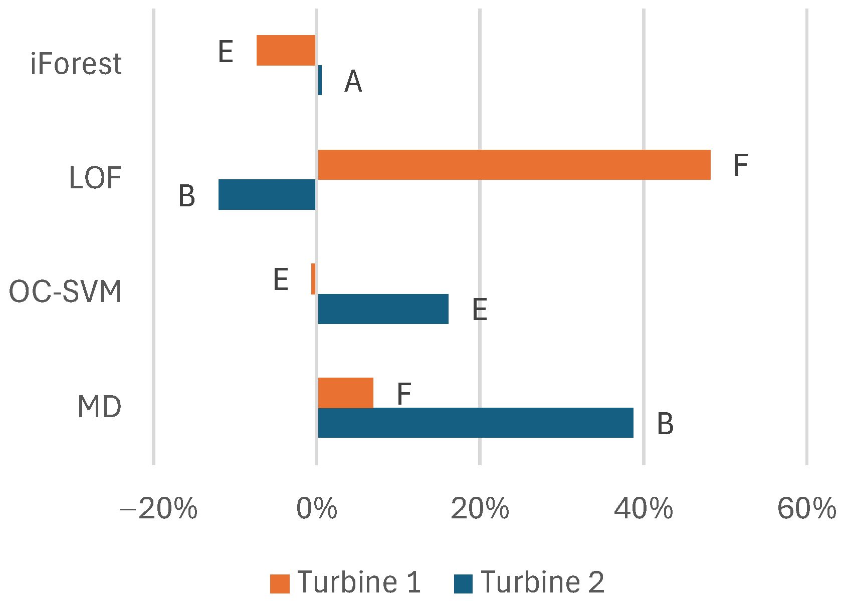
To summarize the results, we can draw conclusions about the feature set, filtering, model selection, and variations among the turbines. Regarding the features, the model benefits overall from the pressures of the raw signals instead of precalculating the differential pressure. Adding information like the minimum and maximum values during the sampling besides the average values benefits most models. Additionally, information about oil temperature adds information about this problem that benefits the models. The system pressure only adds valuable information for some models.
The pre-filtering of data using MAD benefited the models on average. However, for iForest, the drawbacks may, on the other hand, exceed the benefits, and pre-filtering could be excluded. For the other models, it is suggested that the pre-filtering of the data should be kept. However, the possible negative effects can be considered if the models lack performance.
The MDF also provides, on average, positive effects for the models. The choice in feature set also seems important to benefit from the MDF. Bayesian optimization effectively finds the best parameters for the MDF. As the net effect is positive for the best-performing models, it is suggested that the MDF should be included in the model approach for all models. As the performance of the MDF heavily depends on its parameters, the lack of optimization would probably affect the performance of the MDF negatively.
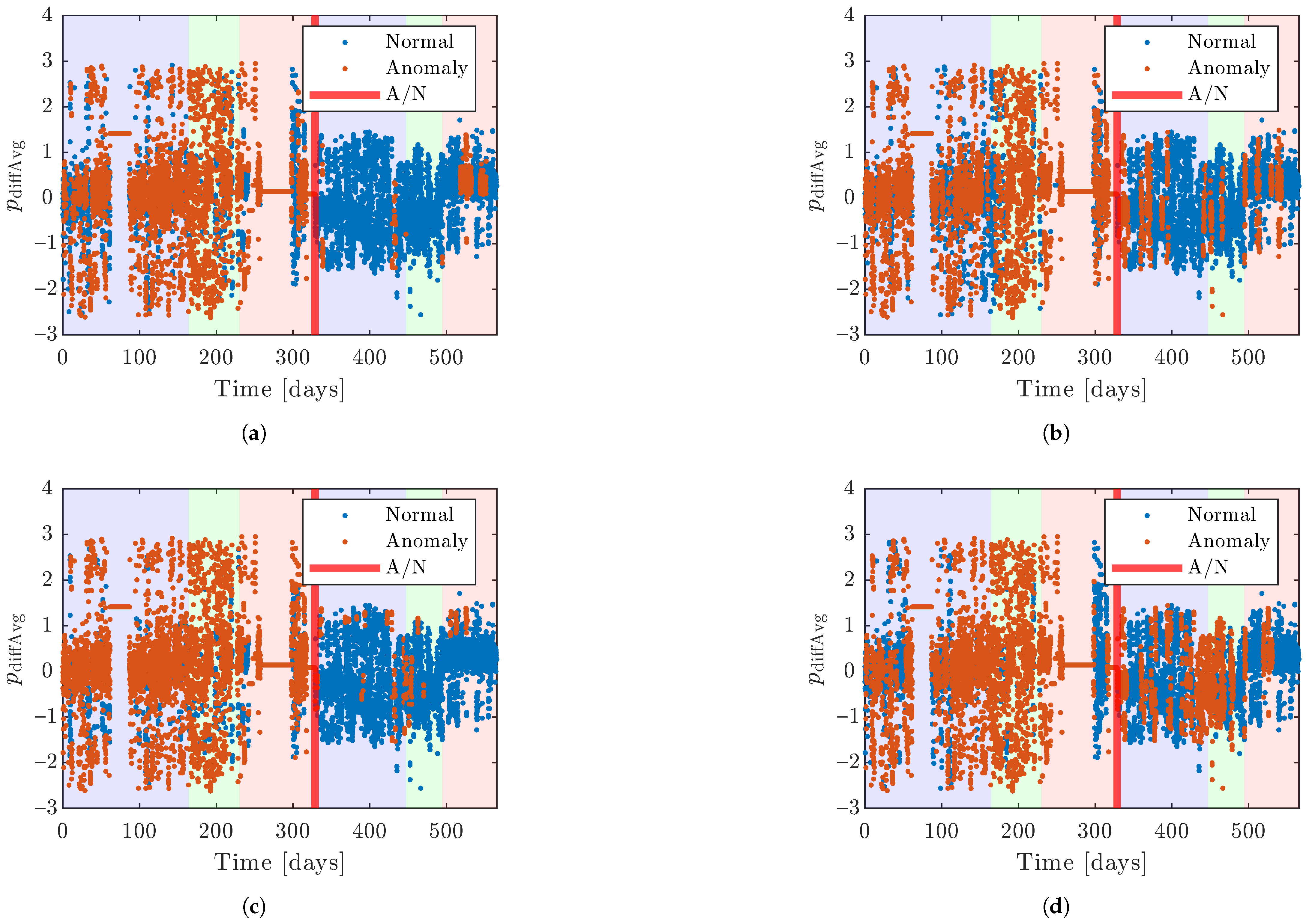
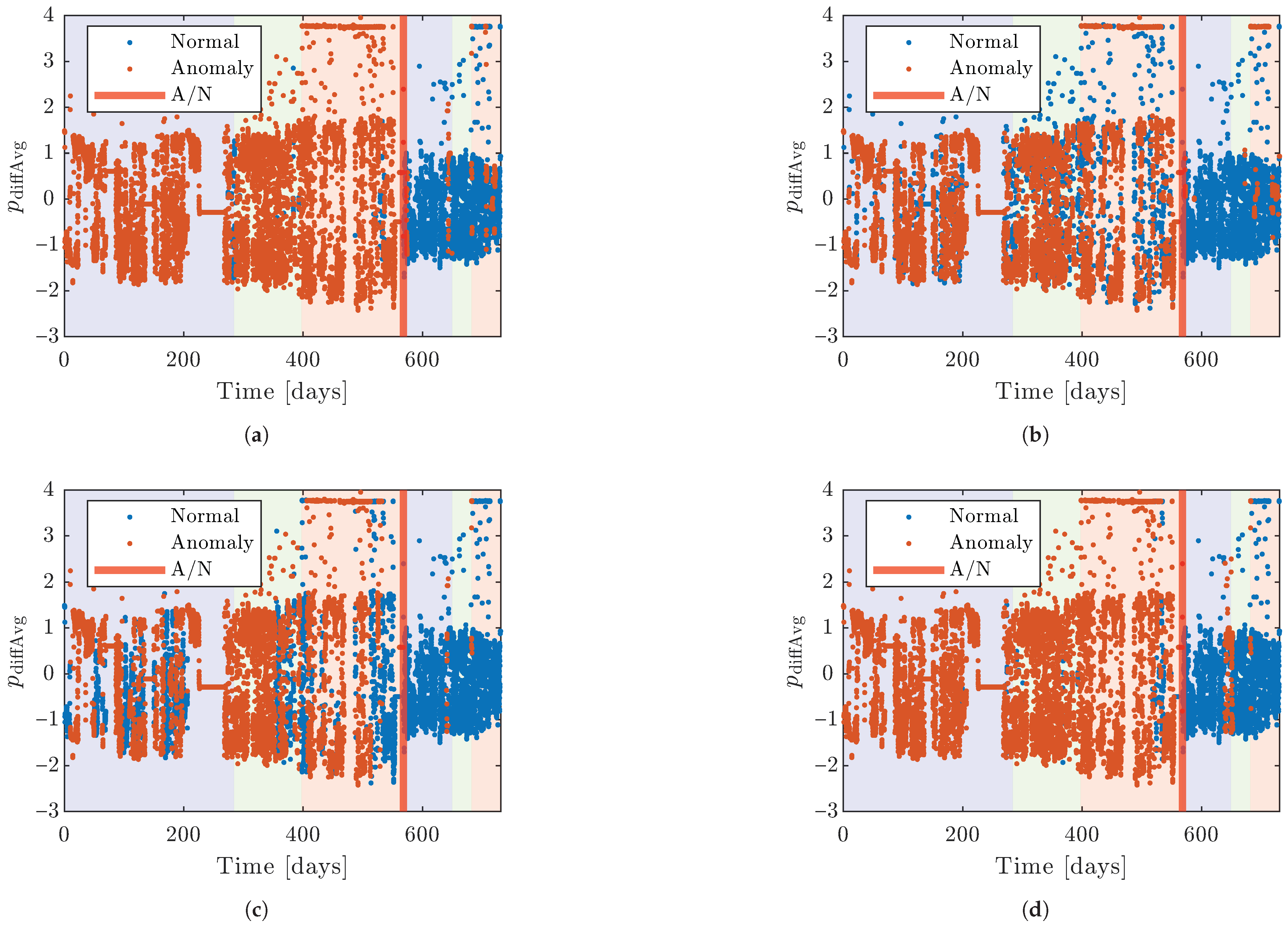
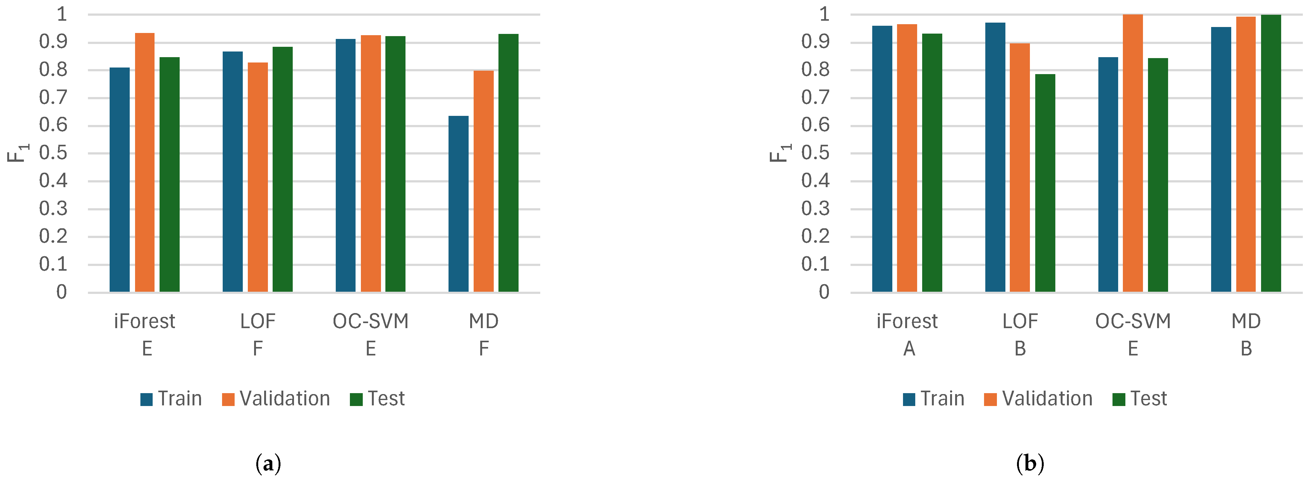
Mahalanobis distance performs best on the test set in this study. However, iForest and one-class support vector machine also perform well here and offer more stable performance over the training, validation, and test sets. The stability could be considered good as there may be few opportunities to test the models on anomalous data in many applications. This is why iForest and one-class support vector machine are suggested as good models to start with.
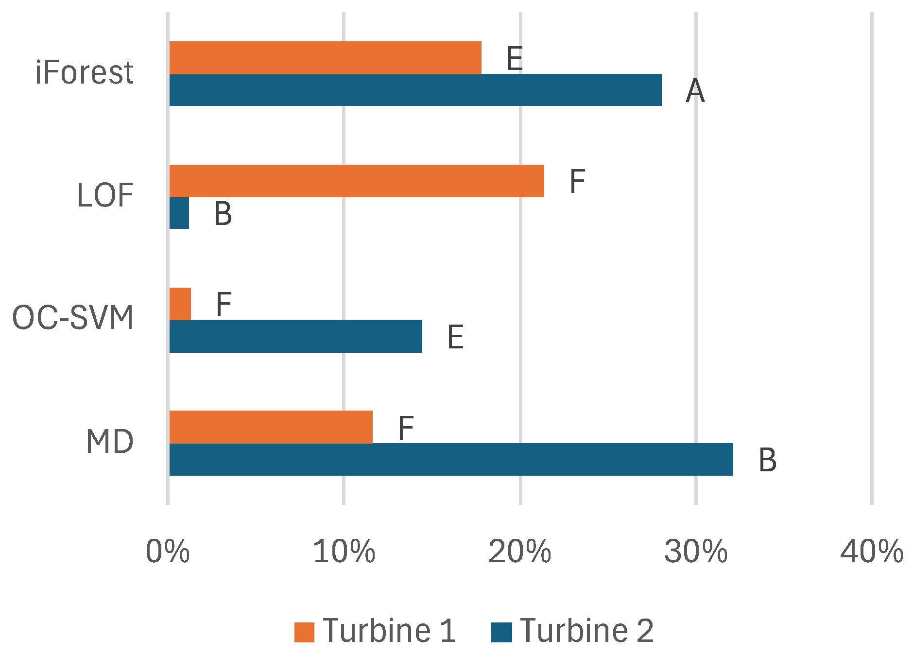
The data are from two Kaplan turbines; the only features separating them are the oil temperature and system pressure. Otherwise, the turbines’ issues are similar. The differences in model performance between the turbines show that we can only have an idea of which models and features to use. This modeling approach can be transferred between turbines, but it is still important to set the hyperparameters using an optimization process specific to each turbine to achieve optimal performance.
This work shows how anomaly detection can be used for friction monitoring in Kaplan turbines. It also suggests a modeling approach for friction monitoring when anomalous data exist, which can help the industry to improve the monitoring of Kaplan turbines.

Author Contributions

Conceptualization, L.-J.S., K.B., P.M. and G.F.S.; methodology, L.-J.S.; software, L.-J.S.; validation, L.-J.S.; formal analysis, L.-J.S.; investigation, L.-J.S. and G.F.S.; resources, G.F.S.; data curation, L.-J.S. and G.F.S.; writing—original draft preparation, L.-J.S.; writing—review and editing, L.-J.S., K.B., P.M. and G.F.S.; visualization, L.-J.S.; supervision, K.B. and P.M.; project administration, K.B.; funding acquisition, K.B. All authors have read and agreed to the published version of the manuscript.

Funding

This research was funded by the Swedish Centre for Sustainable Hydropower—SVC, grant number LTU-3726-2023.

Data Availability Statement

The data used in this study are available at https://doi.org/10.5878/4q73-hp36 (accessed on 12 March 2025).

Acknowledgments

The research presented in this paper was carried out as a part of “Swedish Centre for Sustainable Hydropower”—SVC https://svc.energiforsk.se (accessed on 6 April 2025). SVC has been established by the Swedish Energy Agency, Energiforsk, and Svenska kraftnät together with Luleå University of Technology, Uppsala University, KTH Royal Institute of Technology, Chalmers University of Technology, Karlstad University, Swedish University of Agricultural Sciences, Umeå University, and Lund University. Participating companies and industry associations include AFRY, Andritz Hydro, Boliden, Fortum Sverige, Holmen Energi, Jämtkraft, Karlstads Energi, LKAB, Mälarenergi, Norconsult, Aker Solutions, Skellefteå Kraft, Statkraft Sverige, Sweco Sverige, Tekniska verken i Linköping, Uniper, Umeå Energi, Vattenfall R&D, Vattenfall Vattenkraft, Vattenkraftens miljöfond, Voith Hydro, WSP Sverige, and Zinkgruvan. Fortum Sverige AB is also acknowledged for providing the data used in this study. During the preparation of this manuscript, ChatGPT-4o (by OpenAI) and Grammarly (1.112.1.0) were used for spell-checking, grammar corrections, readability improvements, and structural feedback. ChatGPT-4o was also used as a conversational and brainstorming partner to discuss content, structure, and analyses. The authors have reviewed and edited the output and take full responsibility for the content of this publication.

Conflicts of Interest

Author Gregory F. Simmons is employed by the company Fortum Sverige AB. The remaining authors declare that the research was conducted in the absence of any commercial or financial relationships that could be construed as a potential conflict of interest. The funders had no role in the design of the study; in the collection, analyses, or interpretation of data; in the writing of the manuscript; or in the decision to publish the results.

Abbreviations

CMcondition monitoring
CBMcondition-based maintenance
iForestisolation forest
iTreeisolation tree
KICAkernel independent component analysis
KICA-PCAkernel independent component analysis and principal component analysis
KPIkey performance indicator
LSTMlong short-term memory
MADmedian absolute deviation
MDMahalanobis distance
MDFmoving decision filter
LOFlocal outlier factor
OC-SVMone-class support vector machine
PCAprincipal component analysis
RULremaining useful life
SCADAsupervisory control and data acquisition
SOMself-organizing map
SPEsquared prediction error
SVMsupport vector machine

References

  1. IEA. Hydroelectricity. Available online: https://www.iea.org/energy-system/renewables/hydroelectricity#tracking (accessed on 29 January 2025).
  2. Schaber, K. Integration of Variable Renewable Energies in the European Power System: A Model-Based Analysis of Transmission Grid Extensions and Energy Sector Coupling. Ph.D. Thesis, Technische Universität München, München, Germany, 2014. [Google Scholar]
  3. Delucchi, M.A.; Jacobson, M.Z. Providing all global energy with wind, water, and solar power, Part II: Reliability, system and transmission costs, and policies. Energy Policy 2011, 39, 1170–1190. [Google Scholar] [CrossRef]
  4. Siemonsmeier, M.; Baumanns, P.; van Bracht, N.; Schönefeld, M.; Schönbauer, A.; Moser, A.; Dahlhaug, O.; Heidenreich, S. Hydropower Providing Flexibility for a Renewable Energy System: Three European Energy Scenarios; Technical Report, A HydroFlex Report; HydroFlex: Trondheim, Norway, 2018. [Google Scholar]
  5. Kande, M.; Isaksson, A.; Thottappillil, R.; Taylor, N. Rotating Electrical Machine Condition Monitoring Automation—A Review. Machines 2017, 5, 24. [Google Scholar] [CrossRef]
  6. Tavner, P. Condition Monitoring of Rotating Electrical Machines; The Institution of Engineering and Technology: London, UK, 2020. [Google Scholar]
  7. Tsang, A.H.; Yeung, W.; Jardine, A.K.; Leung, B.P. Data management for CBM optimization. J. Qual. Maint. Eng. 2006, 12, 37–51. [Google Scholar] [CrossRef]
  8. Zhu, W.; Zhou, J.; Xia, X.; Li, C.; Xiao, J.; Xiao, H.; Zhang, X. A novel KICA–PCA fault detection model for condition process of hydroelectric generating unit. Measurement 2014, 58, 197–206. [Google Scholar] [CrossRef]
  9. Betti, A.; Crisostomi, E.; Paolinelli, G.; Piazzi, A.; Ruffini, F.; Tucci, M. Condition monitoring and predictive maintenance methodologies for hydropower plants equipment. Renew. Energy 2021, 171, 246–253. [Google Scholar] [CrossRef]
  10. de Andrade Melani, A.H.; de Carvalho Michalski, M.A.; da Silva, R.F.; de Souza, G.F.M. A framework to automate fault detection and diagnosis based on moving window principal component analysis and Bayesian network. Reliab. Eng. Syst. Saf. 2021, 215, 107837. [Google Scholar] [CrossRef]
  11. Jiang, W.; Xu, Y.; Chen, Z.; Zhang, N.; Xue, X.; Liu, J.; Zhou, J. A feature-level degradation measurement method for composite health index construction and trend prediction modeling. Measurement 2022, 206, 112324. [Google Scholar] [CrossRef]
  12. Ahmed, I.; Dagnino, A.; Ding, Y. Unsupervised Anomaly Detection Based on Minimum Spanning Tree Approximated Distance Measures and its Application to Hydropower Turbines. IEEE Trans. Autom. Sci. Eng. 2018, 16, 654–667. [Google Scholar] [CrossRef]
  13. Pino, G.; Ribas, J.R.; Guimarães, L.F. Bearing Diagnostics of Hydro Power Plants Using Wavelet Packet Transform and a Hidden Markov Model with Orbit Curves. Shock Vib. 2018, 2018, 5981089. [Google Scholar] [CrossRef]
  14. Bütüner, M.A.; Koşalay, İ.; Gezer, D. Machine-Learning-Based Modeling of a Hydraulic Speed Governor for Anomaly Detection in Hydropower Plants. Energies 2022, 15, 7974. [Google Scholar] [CrossRef]
  15. Wang, H.; Liu, X.; Ma, L.; Zhang, Y. Anomaly detection for hydropower turbine unit based on variational modal decomposition and deep autoencoder. Energy Rep. 2021, 7, 938–946. [Google Scholar] [CrossRef]
  16. Åsnes, A.; Willersrud, A.; Kretz, F.; Imsland, L. Predictive maintenance and life cycle estimation for hydro power plants with real-time analytics. In Proceedings of the 2018 HYDRO Conference, Gdansk, Poland, 15–17 October 2018. [Google Scholar]
  17. Liu, F.T.; Ting, K.M.; Zhou, Z.H. Isolation Forest. In Proceedings of the 2008 Eighth IEEE International Conference on Data Mining, Pisa, Italy, 15–19 December 2008. [Google Scholar] [CrossRef]
  18. Breunig, M.M.; Kriegel, H.P.; Ng, R.T.; Sander, J. LOF: Identifying density-based local outliers. ACM Sigmod Rec. 2000, 29, 93–104. [Google Scholar] [CrossRef]
  19. Schölkopf, B.; Platt, J.C.; Shawe-Taylor, J.; Smola, A.J.; Williamson, R.C. Estimating the Support of a High-Dimensional Distribution. Neural Comput. 2001, 13, 1443–1471. [Google Scholar] [CrossRef] [PubMed]
Figure 1. Illustrations of the Kaplan turbine: (a) hydropower plant with Kaplan turbine. Image by Voith Hydro Power Generation, licensed under CC BY-SA 3.0: https://creativecommons.org/licenses/by-sa/3.0/ (accessed on 6 April 2025), via Wikimedia Commons: https://commons.wikimedia.org/wiki/File:S_vs_kaplan_schnitt_1_zoom.jpg (accessed on 4 December 2024). (b) Free body diagram of single runner blade on a Kaplan turbine. (c) Free body diagram that shows the total forces and torques acting on the shaft on an individual runner blade. Adapted from an image by Jahobr, licensed under CC0 1.0: https://creativecommons.org/publicdomain/zero/1.0/ (accessed on 6 April 2025), via Wikimedia Commons: https://commons.wikimedia.org/wiki/File:KaplanSketch.svg (accessed on 31 March 2025).
Machines 13 00313 g001
Figure 2. Histogram of anomaly scores for iForest on the validation set for feature set B. The darker orange indicates where the normal and anomalous data overlap.
Machines 13 00313 g002
Figure 3. F1 score on test set. The letter below each bar group indicates the feature set used. (a) Turbine 1 with MDF models. (b) Turbine 2 with MDF models.
Machines 13 00313 g003
Figure 4. F 1 score on the validation set for the range of thresholds used during Bayesian optimization. The cross marks out the best threshold according to Bayesian optimization. (a) Turbine 1. (b) Turbine 2.
Machines 13 00313 g004
Figure 5. F 1 score on the validation set for the range of window sizes used during Bayesian optimization. The cross marks out the best threshold according to Bayesian optimization. (a) Turbine 1. (b) Turbine 2.
Machines 13 00313 g005
Figure 6. Benefits of pre-filtering the data for each model. The letter next to each bar indicates the feature set used.
Machines 13 00313 g006
Figure 7. The models with the highest F 1 score on the test set for Turbine 1. Blue indicates that the model classifies the data as normal, and orange indicates that the data are classified as anomalous. The vertical red line (A/N) marks the boundary before data are labeled anomalous and after data are labeled normal. The background color shades represent the division into training (blue), validation (green), and test (red) sets. (a) iForest, Turbine 1, feature set E. (b) LOF, Turbine 1, feature set F. (c) One-class support vector machine, Turbine 1, feature set E. (d) Mahalanobis distance, Turbine 1, feature set F.
Machines 13 00313 g007
Figure 8. The models with the highest F 1 score on the test set for Turbine 2. The figure should be interpreted the same way as Figure 7. (a) iForest, Turbine 2, feature set A. (b) LOF, Turbine 1, feature set B. (c) One-class support vector machine, Turbine 2, feature set E. (d) Mahalanobis distance, Turbine 2, feature set B.
Machines 13 00313 g008
Figure 9. F 1 score on training, validation, and test sets for the models with the highest F 1 score on the test set. The letter below the model name indicates the feature set used. (a) Turbine 1. (b) Turbine 2.
Machines 13 00313 g009
Figure 10. Precision on training, validation, and test sets for the models with the highest F 1 score on the test set. The letter below the model name indicates the feature set used. (a) Turbine 1. (b) Turbine 2.
Machines 13 00313 g010
Figure 11. Recall on training, validation, and test sets for the models with the highest F 1 score on the test set. The letter below the model name indicates the feature set used. (a) Turbine 1. (b) Turbine 2.
Machines 13 00313 g011
Figure 12. Benefits of MDF on F 1 score on test set for the models with the highest F 1 score on the test set. The letter next to each bar indicates the feature set used.
Machines 13 00313 g012
Table 1. Datasets used for modeling.
Total PeriodPeriod with GlycerolFeatures
Turbine 1566 days237 days (42%)Closing pressures:
p closeAvg , p closeMin , p closeMax
Opening pressures:
p openAvg , p openMin , p openMax
Oil temperatures:
t oilAvg , t oilMin , t oilMax
Turbine 2731 days163 days (22%)Closing pressures:
p closeAvg , p closeMin , p closeMax
Opening pressures:
p openAvg , p openMin , p openMax
System pressures:
p sysAvg , p sysMin , p sysMax
Table 2. Investigated feature sets.
Feature SetFeatures
A p closeAvg , p openAvg
B p closeAvg , p closeMin , p closeMax , p openAvg , p openMin , p openMax
C p diffAvg
D p diffAvg , p diffMin , p diffMax
EAll features
F3 first PCA components of all features
Table 3. Bayesian optimization results for MDF, showing the optimal window size and threshold for each model, feature set, and turbine. T1 and T2 are referring to Turbine 1 and Turbine 2, respectively.
iForestLOFOC-SVMMD
Feature Set T1T2T1T2T1T2T1T2
AWin.3391939113214224141965
Thres.0.4640.4620.0150.021−0.927−0.9881.3010.980
BWin.28333012642062351211824302
Thres.0.4650.4430.0290.022−0.906−0.9742.1391.468
CWin.114810826011606215654858383
Thres.0.4360.4620.0040.006−1.030−0.9670.2290.878
DWin.410739531433683424911304319632
Thres.0.4200.4100.0210.006−1.016−1.0460.7741.103
EWin.1279342973611313392417013211
Thres.0.5080.5320.0200.031−0.792−0.9712.4453.700
FWin.25429823374051147120933804
Thres.0.5070.4510.0190.021−1.051−0.8331.2261.420
Table 4. Performance for the optimized MDF models on the test set. T1 and T2 are referring to Turbine 1 and Turbine 2, respectively.
iForestLOFOC-SVMMD
Feature Set T1T2T1T2T1T2T1T2
AF10.6660.9310.6660.6820.8550.7350.8110.958
Precission0.5060.8720.5000.8670.8370.5890.7150.919
Recall0.9771.0000.9970.5620.8750.9760.9361.000
BF10.6600.9190.6510.7860.6830.8350.6541.000
Precission0.5000.8500.5900.7550.5590.7850.5141.000
Recall0.9710.9990.7250.8190.8790.8920.8970.999
CF10.6380.7680.6420.7520.6670.7760.6380.769
Precission0.4870.6970.4920.6300.5000.7130.4880.680
Recall0.9230.8550.9230.9331.0000.8510.9220.886
DF10.6830.8050.6100.5960.6960.7280.7410.799
Precission0.5220.7240.5070.4780.5430.5830.6080.738
Recall0.9870.9050.7630.7900.9680.9700.9460.872
EF10.8470.5530.6150.5470.9220.8420.6720.977
Precission0.8141.0000.4940.9270.9581.0000.5291.000
Recall0.8820.3820.8160.3880.8880.7280.9200.954
FF10.8340.6740.8830.3710.9130.6860.9290.665
Precission0.7200.5300.8310.4050.8510.5540.8930.520
Recall0.9890.9250.9430.3430.9830.9010.9670.922
Table 5. Metrics for average performance on Turbine 1 and Turbine 2.
F1 (Test)F1 (Avg)F1 (Std)
iForest0.890.910.08
LOF0.830.870.12
OC-SVM0.880.910.10
MD0.960.880.17
Disclaimer/Publisher’s Note: The statements, opinions and data contained in all publications are solely those of the individual author(s) and contributor(s) and not of MDPI and/or the editor(s). MDPI and/or the editor(s) disclaim responsibility for any injury to people or property resulting from any ideas, methods, instructions or products referred to in the content.

