Article

Deep Transfer Learning-Based Performance Prediction Considering 3-D Flux in Outer Rotor Interior Permanent Magnet Synchronous Motors

1
Department of Automotive Engineering (Automotive-Computer Convergence), Hanyang University, Seoul 04763, Republic of Korea
2
Department of Mechanical, Robotics, and Energy Engineering, Dongguk University, Seoul 04620, Republic of Korea
3
Power Electronics Lab, H & A R & D Center, LG Electronics, Seoul 08592, Republic of Korea
*
Author to whom correspondence should be addressed.
These authors contributed equally to this work.
Machines 2025, 13(4), 302; https://doi.org/10.3390/machines13040302
Submission received: 28 February 2025 / Revised: 1 April 2025 / Accepted: 4 April 2025 / Published: 7 April 2025
(This article belongs to the Special Issue Fault Diagnostics and Fault Tolerance of Synchronous Electric Drives)

Abstract

Accurate performance prediction in the design phase of permanent magnet synchronous motors (PMSMs) is essential for optimizing efficiency and functionality. While 2-D finite element analysis (FEA) is commonly used due to its low computational cost, it overlooks important 3-D flux components such as axial leakage flux (ALF) and fringing flux (FF) that affect motor performance. Although 3-D FEA can account for these flux components, it is computationally expensive and impractical for rapid design iterations. To address this challenge, we propose a performance prediction method for interior permanent magnet synchronous motors (IPMSMs) that incorporates 3-D flux effects while reducing computational time. This method uses deep transfer learning (DTL) to transfer knowledge from a large 2-D FEA dataset to a smaller, computationally costly 3-D FEA dataset. The model is trained in 2-D FEA data and fine-tuned with 3-D FEA data to predict motor performance accurately, considering design variables such as stator diameter, axial length, and rotor design. The method is validated through 3-D FEA simulations and experimental testing, showing that it reduces computational time and accurately predicts motor characteristics compared to traditional 3-D FEA approaches.

1. Introduction

Outer rotor motors can achieve a higher output with lower torque than interior permanent magnet synchronous motors (IPMSMs), which allows for a reduction in the size of the motor. These benefits are widely applied in household appliances such as vacuum cleaners, air conditioners, and washing machines, where high-power-density performance is required. Furthermore, permanent magnet synchronous motors (PMSMs) are used in household appliances that require high efficiency [1,2,3]. Rare earth magnets are primarily used to achieve high efficiency and power density in PMSMs [4]. However, the price of rare earth magnets has been rising due to limited production regions and supply chain instability. Therefore, researchers in the home appliance industry are conducting studies on non-rare earth motors to gain a competitive edge in terms of cost. Non-rare earth magnets generally have lower remanence flux density and coercive force compared to rare earth magnets. As a result, they are more susceptible to fault characteristics such as leakage flux and permanent magnet demagnetization, leading to a more significant performance degradation than rare earth magnets [5]. These characteristics can be quickly predicted using 2-D finite element analysis (FEA), but it is difficult to accurately predict motor performance. For example, axial leakage flux (ALF) cannot be considered using 2-D FEA. Therefore, it is necessary to accurately predict the path of the leaking flux components using 3-D FEA. However, due to the high computational cost of 3-D FEA, it is not suitable for use in the initial design stage. For this reason, analysis techniques using equivalent magnetic circuits (EMCs) or mathematical methods have been proposed as alternatives to 3-D FEA [6,7,8,9]. EMCs and mathematical methods can quickly analyze the air-gap flux density of the motor [10,11,12]. However, since the motor shape and flux paths are assumed, it is difficult to predict fault tolerance occurring within the motor.
This paper proposes a method for predicting the performance of an outer rotor IPMSM based on deep transfer learning (DTL) with respect to design variables. The proposed method reduces computational costs by using small-scale 3-D FEA data [13,14,15]. In addition, it can predict motor performance considering 3-D flux components such as ALF and FF. In Section 2, the effects of ALF and FF on the motor are analyzed with respect to key design variables. The variables closely related to the air-gap flux density are identified through analytical expressions, and the individual influences of ALF and FF on motor performance are investigated. In Section 3, a motor performance prediction framework based on deep transfer learning (DTL) is proposed, considering the impact of ALF and FF. The DTL approach utilizes a deep neural network (DNN) initially trained on a large-scale 2-D FEA dataset and subsequently fine-tuned using a small-scale 3-D FEA dataset. Section 4 presents a finite element analysis (FEA)-based investigation of irreversible demagnetization faults in permanent magnets, aimed at identifying the occurrence and extent of demagnetization in the target motor. Finally, in Section 5, the effectiveness of the proposed method is validated through 3-D FEA results and the experimental testing of a prototype outer rotor IPMSM.

2. Motor Performance Investigation According to Design Variables

In this section, the effects of ALF and FF on motor performance are analyzed. First, the variation in air-gap flux density according to major design variables is discussed using mathematical formulations. Then, the effect of ALF on motor performance based on these design variables is evaluated. Finally, the influence of FF on the performance of outer rotor IPMSMs is investigated.

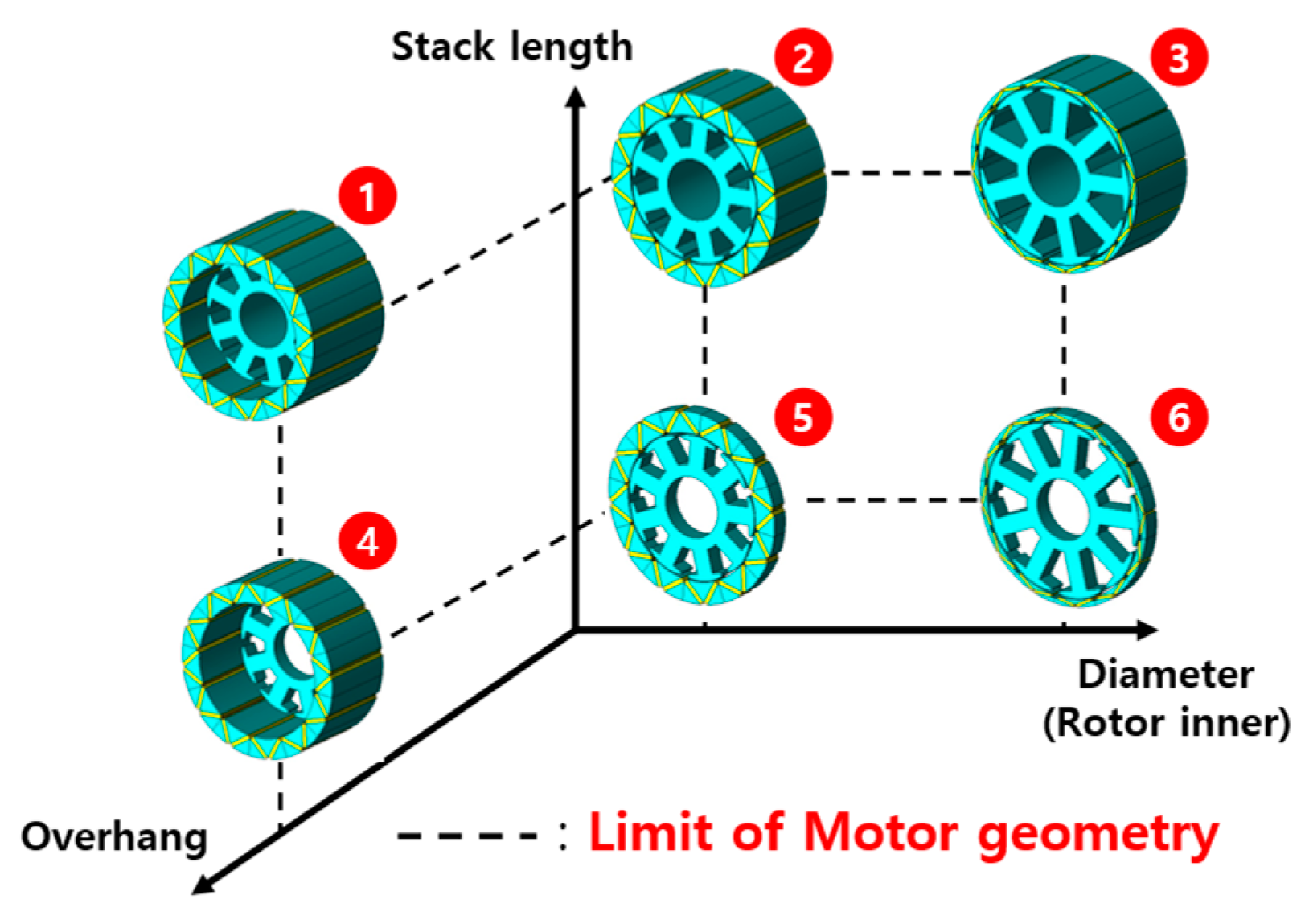
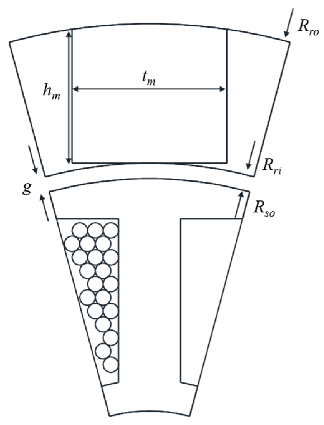
2.1. Motor Geometry According to Design Variables

The design variables of a PMSM, such as the inner and outer diameters of the rotor and the stack length of the rotor and stator, not only influence the electromagnetic characteristics of the motor but also determine its overall geometry, as shown in Figure 1. In outer rotor motors, if the outer diameter of the rotor remains constant while the inner diameter decreases, the proportion of the rotor in the overall motor size increases. This variation directly affects the air-gap flux density. The air-gap flux density, Bg, can be expressed as follows [16]:
B g = B rem π Ds 4 p h m + 2 g μ rec t m B rem   ·   4 p h m π Ds
where Brem is the remanent flux density of the permanent magnet, Ds is the stator diameter, p is the number of pole pairs, hm is the magnet width, g is the air-gap length, μrec is the relative permeability of the permanent magnet, and tm is the magnet thickness. Figure 2 shows the simplified model of the outer rotor IPMSM. By transforming Equation (1) in terms of major design variables, it can be rewritten as Equation (2):
B g     h m D s = ( R ro R ri ) 2 ( R ri g ) = ( R ro R ri ) 2 R so
where Rro is the outer radius of the rotor, Rri is the inner radius of the rotor, and Rso is the outer radius of the stator. Therefore, it can be observed that the air-gap flux density is influenced by the rotor and stator radial.

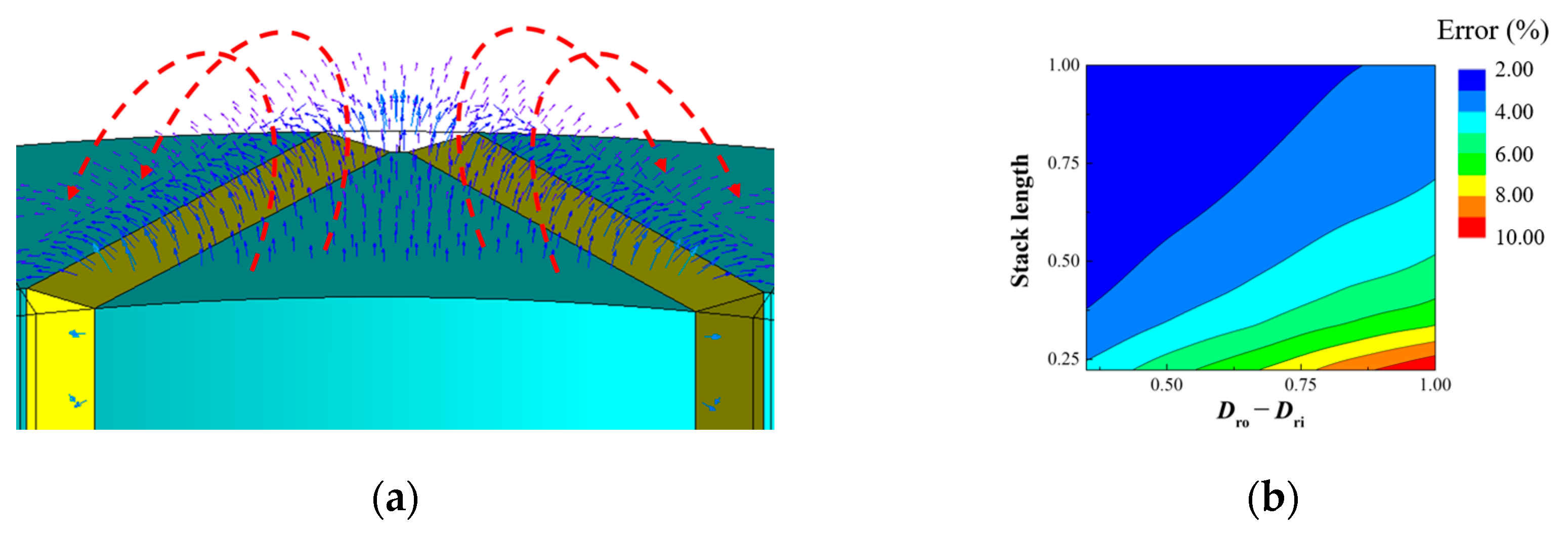
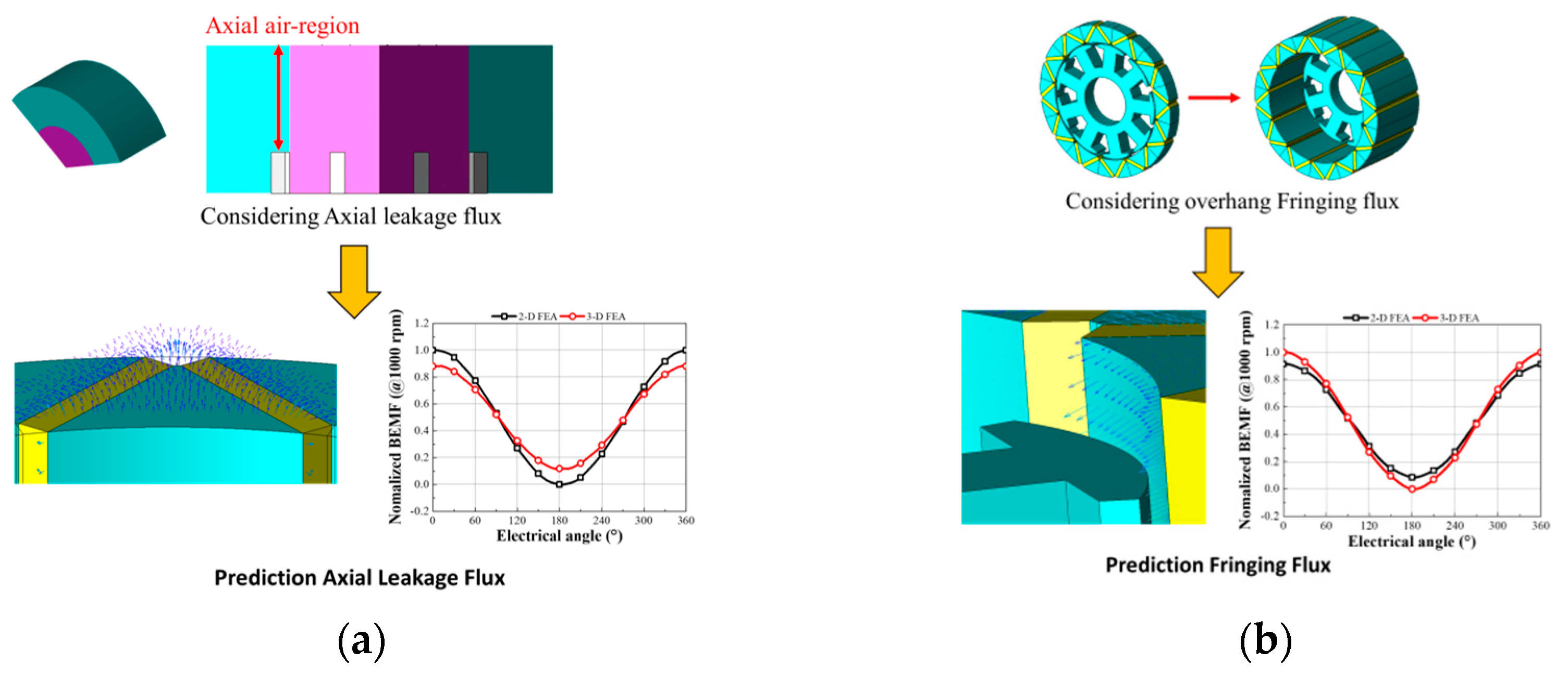
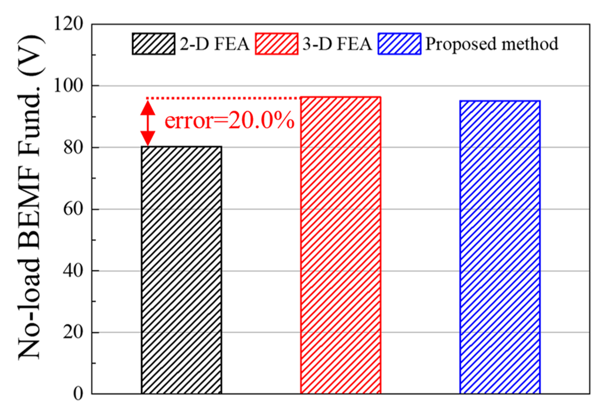
2.2. Axial Leakage Flux in Motor

In this study, the ALF refers to the flux that exists between the rotor core and the axial air region. To accurately assess the impact of ALF, 3-D FEA was conducted by incorporating an air region that sufficiently accounts for the ALF path. The height of the air region varies depending on the design variables of the motor. ALF is generated due to the difference in the magnetic vector potential between the permanent magnets and the core inside the motor. Figure 3a shows the ALF path. Since this flux does not pass through the air-gap, it reduces the back electromotive force (BEMF), leading to a decrease in output power. Figure 3b presents the BEMF error rate between the 2-D and 3-D FEA results as a function of design variable variations. In pancake-type motors, where the difference between the outer and inner rotor diameters is large and the axial length is relatively short, the impact of ALF cannot be neglected. As a result, 3-D FEA is essential for accurately analyzing such motors. However, performing a large number of 3-D FEA simulations to consider ALF variations across different design variables is highly time-consuming. Therefore, a performance prediction approach that incorporates ALF using a limited set of 3-D FEA results is required to achieve accurate and reliable analysis.

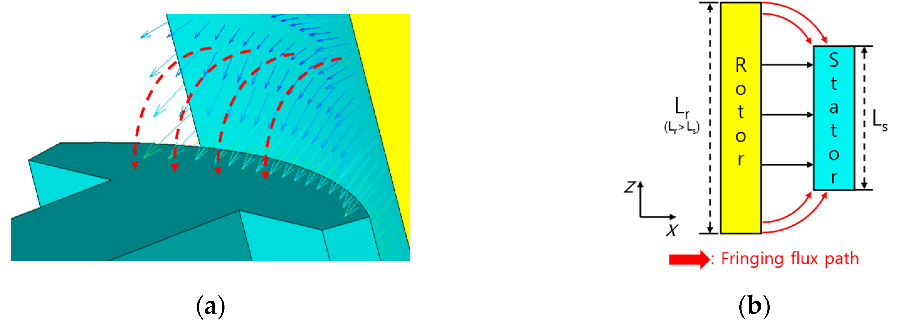
2.3. Fringing Flux Caused by Overhang

The stack length of the motor also affects its performance. In a conventional PMSM, the BEMF, a critical performance indicator, is linearly proportional to the stack length. However, due to the constraints of mold manufacturing costs and limited space, the stack length cannot be increased indefinitely. To maximize the utilization of permanent magnets, an overhang structure is implemented, where the rotor’s stack length is extended beyond that of the stator. Figure 4 shows the FF caused by the overhang structure. Figure 4a shows the path of the motor with overhang applied. A schematic representation of this is shown in Figure 4b. The FF can be seen bending towards the stator core. Under the assumption that the core does not reach saturation, the air-gap flux increases proportionally with the overhang length. Assuming that leakage flux is negligible, the additional flux generated by the overhang can be expressed as Equation (3):
Φ total = Φ g + Φ ovh
where Φtotal is the total air-gap flux, Φg is the air-gap flux when the rotor and stator have the same stack length, and Φovh is to the additional flux contributed by the rotor overhang height.

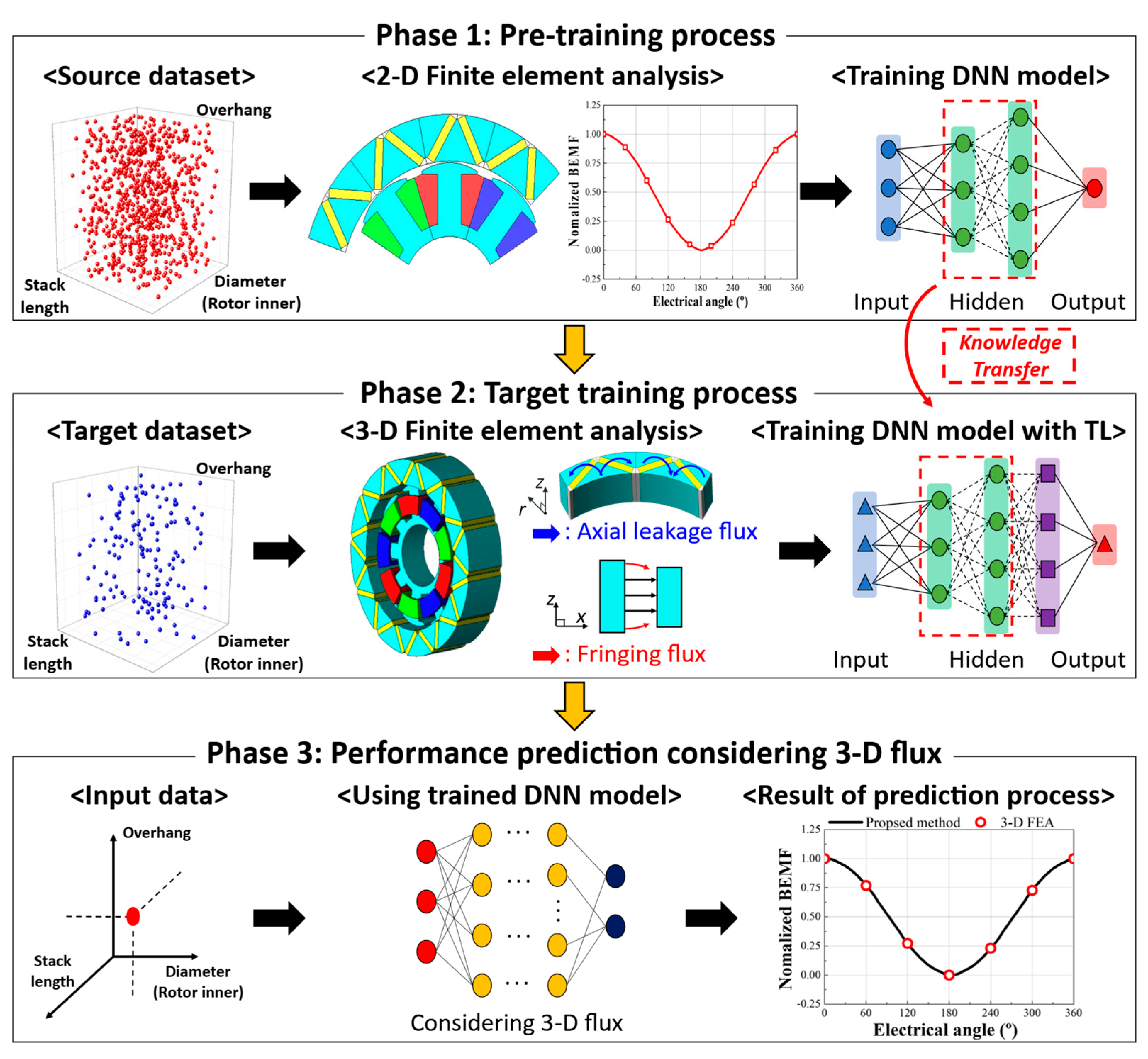
3. Deep Transfer Learning-Based Motor Performance Analysis

In this section, a motor performance prediction method based on DTL is proposed. The proposed approach utilizes DTL to achieve low computational costs while considering ALF and FF. This method uses large-scale 2-D FEA-based results as the source dataset to train a DNN model. The trained DNN model, developed from the source dataset, is then used to build a target DNN model based on 3-D FEA. Finally, the learning rate of the generated DNN model is evaluated, and the accuracy of the predictions is assessed.

3.1. Deep Transfer Learning

In machine learning, it is necessary to train a model to perform a specific task. The training dataset is used to train the DNN model, while the test dataset is used to evaluate the model’s performance. Traditional machine learning models tend to be simple but often exhibit lower accuracy. To improve model accuracy, a DNN with more layers has been adopted. However, using DNN increases the number of weights that must be optimized and requires large-scale datasets. As a result, training large-scale deep learning models can be time-consuming. To reduce the time required for training, transfer learning (TL) is utilized. The definition of TL is as follows: given a source domain Ds, its learning task Ts, a target domain Dt, and a target learning task Tt, where DsDt and TsTt, TL aims to improve learning in Dt by using the information acquired from Ds and Ts. TL is a method of reusing a model trained for one task on another task [17,18,19,20]. Since TL involves using a pre-trained model, separate data training for the target model is not necessary. Thus, the time spent during the training process for the target model can be reduced.

3.2. Proposed Motor Performance Prediction Method

The flowchart of the proposed DTL-based analysis process is shown in Figure 5. First, the DNN model is trained using the source dataset, a process referred to as pre-training. The source dataset consists of 2-D FEA-based results, and achieving high accuracy in the pre-training process requires a large-scale dataset. Therefore, 2-D FEA, which has a shorter computational time, is an appropriate choice. In this study, the fundamental magnitude of the no-load BEMF is used to predict motor performance. While the on-load significantly affects the motor’s characteristics, the air-gap flux density, which has a considerable impact on the output torque, directly influences the no-load BEMF. Therefore, motor performance can be predicted based on the no-load BEMF from open-circuit results, and as such, the fundamental values of the no-load BEMF are used as learning data. The size of the source dataset is set to be 30 times larger than that of the target dataset. The performance of DTL is influenced by the amount of target datasets. In general, accuracy tends to improve as the amount of target data increases. However, as the data volume increases, more data can be obtained, but the time required for data acquisition also increases. The approach proposed in this article aims to reduce the computational time by utilizing a minimal amount of target datasets. In this case, the minimum number of datasets required to predict the accuracy of the learning results is 100 sets of 3-D FEA data. Thus, this article uses 100 sets of 3-D FEA data. Next, the target dataset is used for further training. The target dataset consists of 3-D FEA data, which incorporates the ALF and FF, and utilizes a smaller dataset. Figure 6 presents the conditions applied in the 3-D FEA to predict the ALF and FF. To sufficiently account for the ALF path, an air region with adequate height is applied, as illustrated in Figure 6a. Figure 6b shows the rotor structure-applied overhang. The results of the no-load BEMF are calculated using various combinations of rotor and stator stack length. Since 3-D FEA has a high computational cost, generating a large-scale dataset is time-consuming. Thus, to improve efficiency, the 3-D FEA-based training dataset is trained using TL, leveraging parts of the pre-trained DNN model from the pre-training stage. Finally, the trained target DNN model can be used to predict motor performance while considering ALF and FF based on the desired design variables.

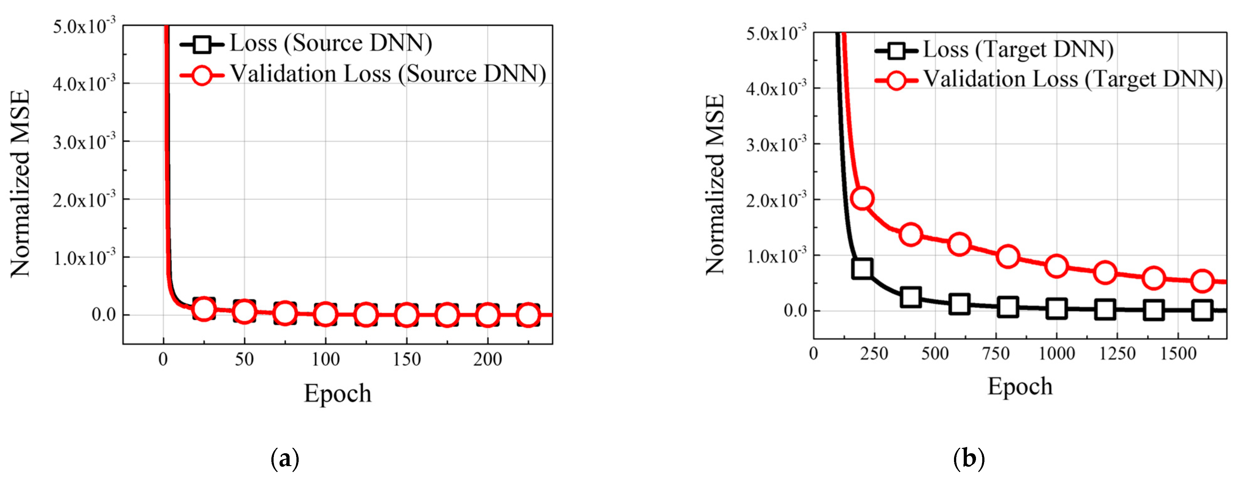
3.3. DTL Models: Validation and Performance Evaluation

The number of datasets used to construct the model and the analysis details are presented in Table 1. An adequate number of data points from the source dataset was used to train the source DNN model. The detailed configuration of the DNN and the number of source and target datasets are provided in Table 1. When training the target DNN, the process involves transferring the weights of six layers from the source model. The learning rate, number of hidden layers, and the number of units per layer are set to 1 × 10⁻⁵, 4, and 256, respectively. To evaluate the performance of the DNN model on the generated target dataset, the training and validation datasets were split in a 5:1 ratio. The learning curves of the TL process are shown in Figure 7. Figure 7a illustrates the training results of the source model. Due to the sufficiently large number of data points in the source dataset, the training and validation loss of the source DNN model converged to low mean squared error (MSE) values without overfitting. The training results of the target DNN model are shown in Figure 7b. The target DNN trained using TL leverages domain knowledge from the source dataset. As a result, the MSE of the DNN model converges to low values for both the training and validation datasets. Figure 8 shows a comparison between the predicted and actual values for the test dataset. Here, the normalized root mean squared error (NRMSE) is 0.14%, indicating that the regression performance on the test dataset is highly accurate. Consequently, utilizing DTL allows for accurate motor performance prediction using a small-scale dataset.

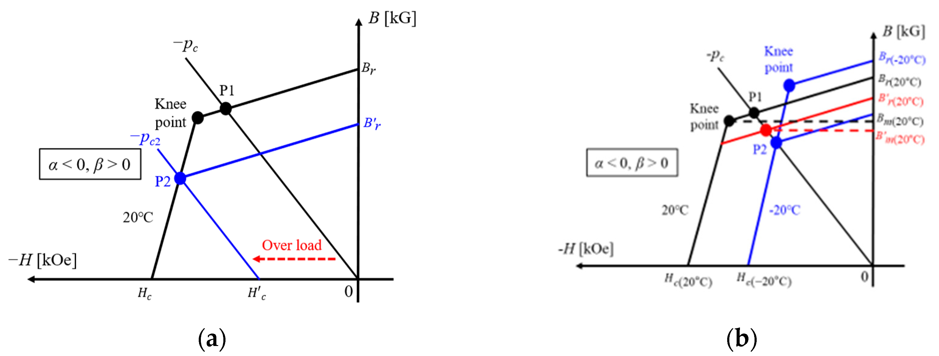
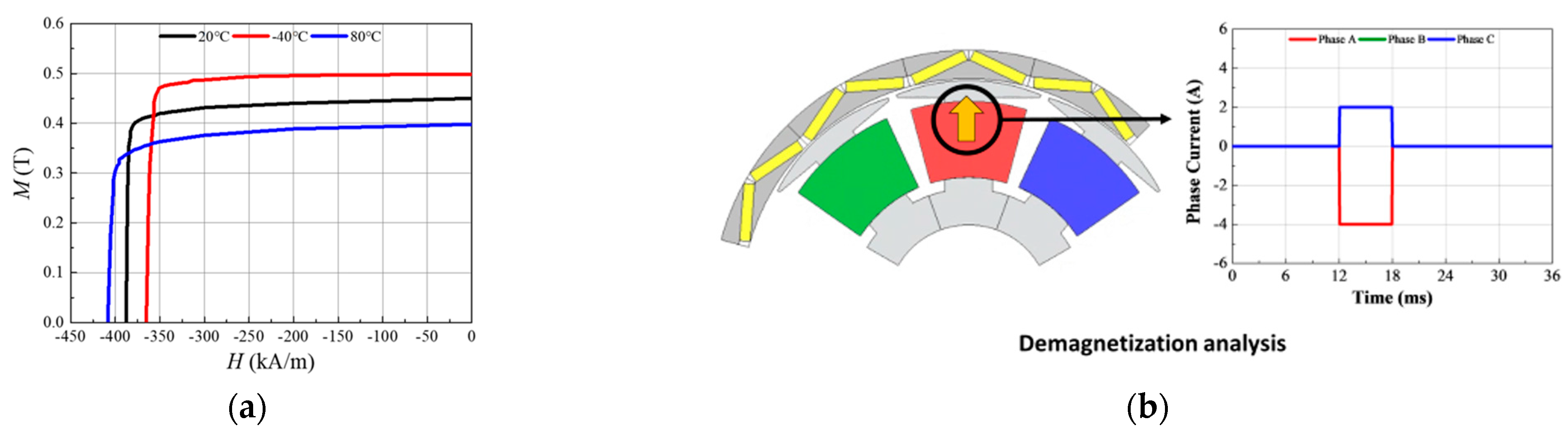
4. Analysis of Irreversible Demagnetization Fault of Motor

The irreversible demagnetization of permanent magnets is one of the critical faults that degrade motor performance [21]. The primary causes of irreversible demagnetization include overload, temperature, and permeance. This section provides a detailed explanation of irreversible demagnetization faults caused by overload and temperature, as well as the demagnetization analysis conditions used in this study.

4.1. Irreversible Demagnetization Fault

The demagnetization of permanent magnets is influenced by variations in stator current and temperature [22,23]. Figure 8 shows irreversible demagnetization in permanent magnets. In Figure 9a, when the permanent magnet operates under normal conditions, the operating point is located at P1, and the remanent flux density of the magnet follows the recoil line, returning to Br. As the load increases, the operating point shifts from P1 to P2. In this case, instead of returning to Br, the magnet follows a new recoil line and reaches a reduced remanent flux density Br′, leading to irreversible demagnetization. In this case, instead of returning to Br, the magnet follows a new recoil line and reaches a reduced remanent flux density Br′, leading to irreversible demagnetization. Figure 9b shows irreversible demagnetization caused by temperature variations. When the temperature decreases from 20 °C to −20 °C, the operating point moves from P1 to P2. As a result, the remanent flux density follows a new recoil line and settles at a lower value, Br′, indicating irreversible demagnetization. This reduction in remanent flux density ultimately leads to a decline in motor performance.

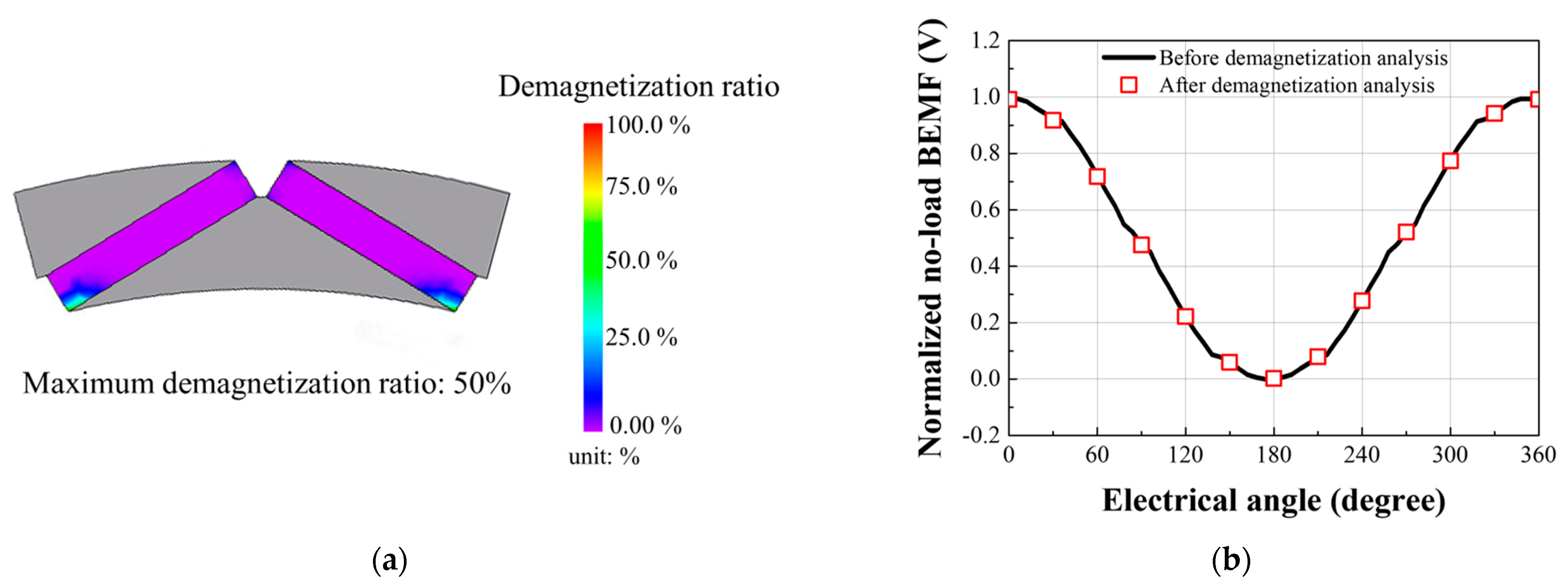
4.2. Demagnetization Analysis

The conditions of demagnetization analysis are shown in Figure 10. Figure 10a shows the B-H curves of the magnets used in this study at different temperatures. The simulations in this study incorporate these characteristics. Figure 10b shows the current direction and input current of the demagnetization analysis condition. In the simulations, the current direction was configured to generate a reversible magnetic field capable of inducing irreversible demagnetization. The current magnitude was set to twice the maximum load (3.3 A), and the ferrite magnet’s low-temperature demagnetization characteristics were considered by applying a temperature of −20 °C. The demagnetization fault level of the permanent magnet is using the demagnetization ratio, which is expressed as follows Equation (4):
Demagnetization ratio ( % ) = 100 × 1 B r B r
where Br is before the demagnetization analysis residual induction of the magnet and Br′ is after the demagnetization analysis residual induction of the magnet. If the fundamental amplitude of the no-load BEMF differs by over 2.0%, irreversible demagnetization is diagnosed in this study.

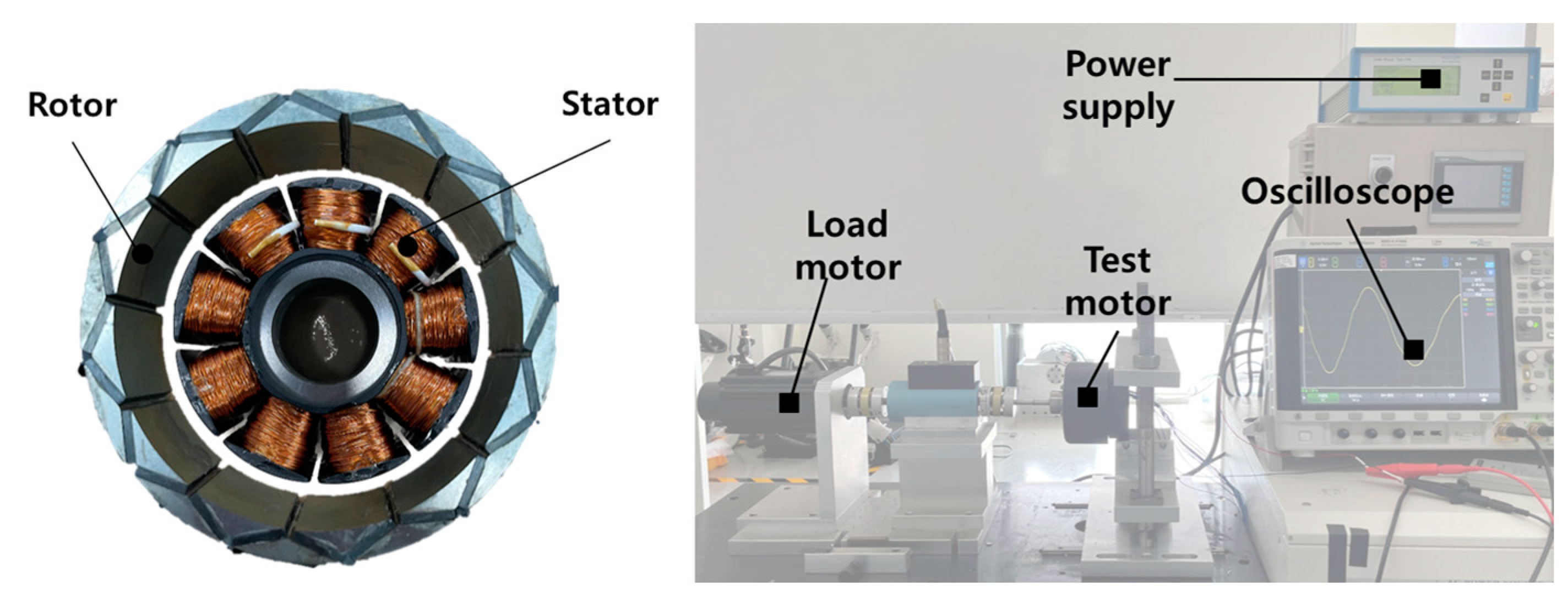
5. Simulation Result and Experimental Verification

To validate the proposed method, the magnitude of the no-load BEMF fundamental was compared for simulation purposes. Figure 11 compares the magnitude of the no-load BEMF fundamental for the proposed method and the 2-D/3-D FEA methods. Assuming that the 3-D FEA represents the true value, the results from the 2-D FEA show an error of approximately 20.0%. This is because 2-D FEA cannot account for ALF and the overhang structure. However, the error between the proposed method and the 3-D FEA is only 1.20%, indicating a close match. The time required for each analysis method is presented in Table 2. The analysis time for 3-D FEA is the longest, consuming 36 times more time than the proposed method. It is expected that the computational time will significantly increase as the number of analysis cases increases. The result of the irreversible demagnetization analysis of the permanent magnet is presented in Figure 12. The demagnetization ratio of the permanent magnets after applying the overload current is presented in Figure 12a. It can be observed that a partial demagnetization fault occurs at the edges of the magnets. Figure 12b presents the normalized no-load BEMF before and after the demagnetization analysis. As the reduction ratio of the BEMF is less than 1%, an irreversible demagnetization fault is not observed.
To experimentally validate the proposed method, a prototype was fabricated. The specifications of the prototype are shown in Table 3. The rotor inner diameter of the prototype is 85% of the rotor outer diameter, and the overhang length of the rotor is approximately 44% longer than the stator’s lamination length. The fabricated prototype and test setup are shown in Figure 13. The tests were conducted at no-load and 1000 rpm. Figure 14 compares the test and simulation results, showing that the magnitudes of the no-load BEMF fundamental for 3-D FEA, the test, and the proposed method are nearly identical. The error rates for 3-D FEA and the proposed method, compared to the test results, are both below 3%, demonstrating the reliability of the proposed method.

6. Conclusions

This article presents an efficient method for predicting the performance of an outer rotor IPMSM, considering axial leakage flux and demagnetization, using deep transfer learning. The axial leakage flux and demagnetization ratio were considered based on design variables such as the rotor inner diameter, lamination length, and overhang ratio. In the case of 3-D FEA, the motor geometry and flux path can be accurately accounted for. However, the computational time is inefficient in the initial design phase. The proposed method uses a large-scale 2-D FEA-based dataset to reduce computational cost and predict performance by leveraging deep transfer learning, overcoming the computational inefficiency of 3-D FEA. The small-scale 3-D FEA results are incorporated into the transfer learning process to explain axial leakage flux and permanent magnet demagnetization. As a result, the no-load BEMF of the motor, considering each fault characteristic, can be predicted with high accuracy by performing a small number of 3-D FEA simulations. Finally, a prototype was fabricated to experimentally validate the proposed method, and the test results confirmed the validity of the proposed method. The findings of this article will help to quickly predict the performance of an outer rotor IPMSM in the early stages of design, considering various design variables.

Author Contributions

Conceptualization, M.-H.S.; methodology, M.-H.S., K.-S.C., and S.-H.P.; software, S.-H.P.; investigation, K.-S.C.; writing—original draft, M.-H.S.; writing—review and editing, M.-H.S., K.-S.C., and M.-S.L.; supervision, M.-S.L.; project administration, M.-S.L. and J.-H.S. All authors have read and agreed to the published version of the manuscript.

Funding

This research received no external funding.

Data Availability Statement

The original contributions presented in this study are included in the article. Further inquiries can be directed to the corresponding author.

Conflicts of Interest

The author Jae-Han Sim was employed by the company LG Electronics. The remaining authors declare that the research was conducted in the absence of any commercial or financial relationships that could be construed as a potential conflict of interest.

References

  1. Jung, J.-W.; Jung, D.-H.; Lee, J. A Study on the Design Method for Improving the Efficiency of Spoke-Type PMSM. IEEE Trans. Magn. 2023, 59, 8200205. [Google Scholar] [CrossRef]
  2. Park, C.-S.; Kim, J.-H.; Park, S.-H.; Yoon, Y.-D.; Lim, M.-S. Multi-Physics Characteristics of PMSM for Compressor According to Driving Mode Considering PWM Frequency. IEEE Access 2022, 10, 114490–114500. [Google Scholar] [CrossRef]
  3. Li, L.; Zhang, J.; Zhang, C.; Yu, J. Research on Electromagnetic and Thermal Issue of High-Efficiency and High-Power-Density Outer-Rotor Motor. IEEE Trans. Appl. Supercond. 2016, 26, 5204805. [Google Scholar]
  4. Chen, H.; Demerdash, N.A.O.; El-Refaie, A.M.; Guo, Y.; Hua, W.; Lee, C.H.T. Investigation of a 3D-Magnetic Flux PMSM with High Torque Density for Electric Vehicles. IEEE Trans. Energy Convers. 2022, 37, 1442–1454. [Google Scholar]
  5. Lee, S.G.; Bae, J.; Kim, W.-H. Study on the Axial Leakage Magnetic Flux in a Spoke Type Permanent Magnet Synchronous Motor. IEEE Trans. Ind. Appl. 2019, 55, 5881–5887. [Google Scholar] [CrossRef]
  6. Jung, J.-W.; Park, H.-I.; Hong, J.-P.; Lee, B.-H. A Novel Approach for 2-D Electromagnetic Field Analysis of Surface Mounted Permanent Magnet Synchronous Motor Taking Into Account Axial End Leakage Flux. IEEE Trans. Magn. 2017, 53, 8208104. [Google Scholar]
  7. Jung, J.-W.; Jung, K.-T.; Lee, B.-H.; Hong, J.-P. Design and Analysis of Ferrite Magnet Flux Concentrated PMSM with Cross-Laminated Rotor Core Using Equivalent 2-D FEA. IEEE Trans. Energy Convers. 2019, 34, 1623–1631. [Google Scholar]
  8. Seok, C.-H.; Yoon, S.-Y.; Choi, H.-S.; Lee, H.-Y.; Seo, J. Analysis and Modeling of Axial Leakage for Spoke-Type Hybrid Permanent Magnet Machines. IEEE Access 2023, 11, 6385–6393. [Google Scholar]
  9. Lee, S.G.; Bae, J.-N.; Kim, M.; Kim, W.-H. Study on the Improvement of the Correction Coefficient Considering the 3-D Effect of Spoke-Type Permanent-Magnet Synchronous Motor. IEEE Trans. Mag. 2020, 56, 7513405. [Google Scholar]
  10. Xiao, C.; Han, A.; Xie, W.; He, M. Fast Design of Spoke-Type PM Motor with Auxiliary Notches Based on Lumped-Parameter Magnetic Equivalent Circuit Model and Hybrid Multiobjective Optimizer. IEEE Access 2022, 10, 99421–99434. [Google Scholar]
  11. Saneie, H.; Nasiri-Gheidari, Z. Performance Analysis of Outer-Rotor Single-Phase Induction Motor Based on Magnetic Equivalent Circuit. IEEE Trans. Ind. Electron. 2021, 68, 1046–1054. [Google Scholar] [CrossRef]
  12. Watthewaduge, G.; Bilgin, B. Reluctance Mesh-Based Magnetic Equivalent Circuit Modeling of Switched Reluctance Motors for Static and Dynamic Analysis. IEEE Trans. Transp. Electrif. 2022, 8, 2164–2176. [Google Scholar] [CrossRef]
  13. Won, Y.-J.; Kim, J.-H.; Park, S.-H.; Lee, J.-H.; An, S.-M.; Kim, D.-Y.; Lim, M.-S. Transfer Learning-Based Design Method for Cogging Torque Reduction in PMSM with Step-Skew Considering 3-D Leakage Flux. IEEE Trans. Magn. 2023, 59, 8204905. [Google Scholar] [CrossRef]
  14. Lee, J.H.; Park, S.H.; Kim, P.J.; Park, D.H.; Lim, M.S. Two-Dimensional FEA-Based Iron Loss Calculation Method for Linear Oscillating Actuator Considering the Circumferential Segmented Structure. IEEE Trans. Magn. 2023, 59, 1–5. [Google Scholar] [CrossRef]
  15. Bian, Y.; Wen, X.; Fan, T.; Li, H.; Liu, Z. Data-Driven-Model-Based Full-Region Optimal Mapping Method of Permanent Magnet Synchronous Motors in Wide Temperature Range. Machines 2023, 11, 324. [Google Scholar] [CrossRef]
  16. Bianchi, N.; Jahns, T.M. Design, Analysis, and Control of Interior PM Synchronous Machines. Presented at the IEEE Industry Applications Society Annual Meeting, Seatle, WA, USA, 3 October 2004; pp. 3–9. [Google Scholar]
  17. Khan, A.; Mohammadi, M.H.; Ghorbanian, V.; Lowther, D. Efficiency Map Prediction of Motor Drives Using Deep Learning. IEEE Trans. Mag. 2020, 56, 7511504. [Google Scholar] [CrossRef]
  18. Shao, S.; McAleer, S.; Yan, R.; Baldi, P. Highly Accurate Machine Fault Diagnosis Using Deep Transfer Learning. IEEE Trans. Ind. Inf. 2019, 15, 2446–2455. [Google Scholar] [CrossRef]
  19. Asanuma, J.; Doi, S.; Igarashi, H. Transfer Learning Through Deep Learning: Application to Topology Optimization of Electric Motor. IEEE Trans. Magn. 2020, 56, 7512404. [Google Scholar] [CrossRef]
  20. Park, S.-H.; Chin, J.-W.; Cha, K.-S.; Lim, M.-S. Deep Transfer Learning-Based Sizing Method of Permanent Magnet Synchronous Motors Considering Axial Leakage Flux. IEEE Trans. Mag. 2022, 58, 8206005. [Google Scholar] [CrossRef]
  21. Jeong, C.-L.; Hur, J. Optimization Design of PMSM with Hybrid-Type Permanent Magnet Considering Irreversible Demagnetization. IEEE Trans. Magn. 2017, 53, 8110904. [Google Scholar] [CrossRef]
  22. Hwang, K.-Y.; Yoon, K.-Y. Fault-Tolerant Design Process of Spoke-Type IPM Motor Considering Irreversible Demagnetization of PM in Integrated Electric Brake System. IEEE Trans. Mag. 2022, 58, 8206809. [Google Scholar] [CrossRef]
  23. Kang, Y.; Yao, L. Fault Diagnosis for Permanent Magnet Synchronous Motor with Demagnetization Fault and Sensor Fault. IEEE Trans. Instrum. Meas. 2024, 73, 3533311. [Google Scholar] [CrossRef]
Figure 1. Motor shape based on design variables.
Machines 13 00302 g001
Figure 2. Simplified model of the outer rotor IPMSM.
Machines 13 00302 g002
Figure 3. Axial leakage flux: (a) path of ALF; (b) no-load BEMF differences between 3-D and 2-D FEA according to the design variables.
Machines 13 00302 g003
Figure 4. Fringing flux caused by overhang structure: (a) path of fringing flux; (b) schematic diagram of overhang structure.
Machines 13 00302 g004
Figure 5. The flowchart of the proposed DTL-based analysis process.
Machines 13 00302 g005
Figure 6. Analysis condition of 3-D FEA: (a) prediction axial leakage flux; (b) prediction fringing flux.
Machines 13 00302 g006
Figure 7. Learning curves of DNN models: (a) source DNN model for predicting BEMF; (b) target DNN model for predicting BEMF.
Machines 13 00302 g007
Figure 8. Comparison of ground truth and predicted values for no-load BEMF.
Machines 13 00302 g008
Figure 9. Irreversible demagnetization of permanent magnet: (a) demagnetization caused by overload; (b) demagnetization caused by temperature.
Machines 13 00302 g009
Figure 10. Demagnetization analysis conditions: (a) B-H curve of permanent magnet; (b) the current direction of demagnetization analysis.
Machines 13 00302 g010
Figure 11. Comparison fundamental magnitude of no-load BEMF using 2-D/3-D FEA and proposed method results.
Machines 13 00302 g011
Figure 12. Result of demagnetization analysis: (a) demagnetization ratio of permanent magnet; (b) normalized no-load BEMF fundamental amplitude before and after demagnetization analysis.
Machines 13 00302 g012
Figure 13. Fabricated prototype model and test setup.
Machines 13 00302 g013
Figure 14. Comparison of results with experiments.
Machines 13 00302 g014
Table 1. Learning method setting.
ItemValue
Input componentsDri, stack length, rotor overhang
Output componentsNo-load BEMF
Number of datasets3000 (Source, 2-D FEA)100 (Target, 3-D FEA)
Loss functionMean squared error (MSE)
Number of hidden layers4
Activation functionReLU
OptimizerAdam
Table 2. Consuming analysis time of each method.
Analysis MethodUnitValue
2-D FEAminute0.16
3-D FEA180
Proposed method5.0
Table 3. Specifications of the prototype motor.
ItemUnitValue
Motor type-Outer rotor IPMSM
Permanent magnet-Ferrite
Stator/rotor core-35PN270
Stator/rotor diameter ratio%85.00
Stator stack lengthp.u.1.00
Rotor stack lengthp.u.1.44
Phase per turn-720
Slot fill factor%83.00
Current densityArms/mm24.90
Disclaimer/Publisher’s Note: The statements, opinions and data contained in all publications are solely those of the individual author(s) and contributor(s) and not of MDPI and/or the editor(s). MDPI and/or the editor(s) disclaim responsibility for any injury to people or property resulting from any ideas, methods, instructions or products referred to in the content.

