1. Introduction
Deployable structures have seen growing applications in aerospace, robotics, and related engineering fields, with their lightweight and efficient designs significantly improving space utilization [
1,
2,
3]. In aerospace, Kim’s team [
4] developed scissor-like foldable trusses for flat storage, while Han’s group [
5,
6,
7] enhanced satellite antenna systems through hexagonal prism mechanisms and rectangular pyramid units, demonstrating reliable kinematic control in dynamic environments.
Origami-inspired approaches have opened new design possibilities, as shown in
Figure 1. Carefully engineered crease patterns enable flat sheets to fold into compact forms and deploy into complex 3D shapes [
8]. Fundamental folding mechanisms were established through studies on multi-vertex configurations [
9,
10,
11], while subsequent engineering applications explored programmable curved surfaces [
12,
13]. Building on these principles, Vlachaki et al. [
9] integrated origami with vaulted structures, and Tang’s team [
10] created rotating space-deployable devices using spiral crease patterns. Communication technology applications include Zhang’s reconfigurable antennas [
11], supported by Fonseca’s mechanical framework [
12]. These innovations extend to modular units [
14,
15,
16,
17] and multi-scale control systems coordinating microscopic folding with macroscopic deployment [
16,
17,
18].
The design methods of origami mechanisms come from various sources [
19]. They include mathematical derivations [
20,
21] and inspirations from nature, which artists and scientists have observed and summarized. Many biological structures in nature offer valuable insights for origami design [
22,
23,
24]. For example, the wings of beetles provide unique inspiration [
24]. Their fan-shaped wings, with radially arranged venation patterns, show a natural single-vertex multi-crease origami (SVMCO) design (
Figure 1d). In this structure, several folds converge at a central point to enable compact folding and rapid deployment. By mimicking these efficient folding and unfolding mechanisms from nature, origami designs can achieve compact storage and, when unfolded, a larger functional form.
Figure 1.
Applications of deployable origami structures in aerospace: (
a) NASA’s Lucy mission, (
b) deployable antenna [
25], (
c) foldable telescopic lens [
26], and (
d) origami inspired by insect wings [
24].
Figure 1.
Applications of deployable origami structures in aerospace: (
a) NASA’s Lucy mission, (
b) deployable antenna [
25], (
c) foldable telescopic lens [
26], and (
d) origami inspired by insect wings [
24].
This form of origami creates multiple creases emanating from a single point, allowing for the construction of highly intricate and complex geometric forms [
27,
28]. In contrast to traditional origami, which distributes creases across several vertices, SVMCO focuses on concentrating creases at a single vertex [
29]. This approach offers new possibilities for creating more compact and efficient designs, especially in applications that require precise control over shape transformation. SVMCO is particularly useful in deployable structures and mechanical metamaterials [
30,
31,
32,
33], where manipulating multiple creases from a single vertex enhances control over movement and transformation.
Single-vertex multi-crease origami (SVMCO) structures use circular folding patterns that work like mechanical linkages. Researchers have found that their folding behaviours depend heavily on three key factors: the angles between creases, the length of folds, and how thick the panels are [
34,
35,
36]. For example, studies show that changing the central angle of folds—like switching from 60° to 90° designs—can drastically affect how these structures move and hold weight [
37,
38]. To ensure smooth deployment, engineers carefully plan the crease patterns. They create alternate mountain and valley folds in radiating patterns to reduce stress and use computer models to balance movement and material strain [
39,
40,
41]. Recent improvements focus on making these structures lighter yet strong. One method thins out non-essential panels without losing stiffness [
42,
43], while another uses algorithms to design folds that absorb energy better [
44].
Although progress has been made in SVMCO-based designs, research is still ongoing, with several challenges and gaps remaining. Most existing studies focus on arrays with a small number of units, and there is limited research on how the number of units affects overall folding and unfolding characteristics. Furthermore, many studies are based on idealized models without considering the real-world challenges of thickened panels, which are critical for engineering applications. Addressing these issues will help explore the unique properties of SVMCO and provide references for designing deployable structures, especially those that require precise shape control.
To address these issues in current origami models, this study develops a new mathematical model by analysing the umbrella-like structure of the frilled lizard’s frills. The model incorporates panel thickness to better simulate structural behaviour in real-life applications. Specifically, it will analyse how the number of units affects foldability and deployment efficiency and explore how adjusting the panel angle ratios and thickness can optimize the SVMCO design to improve foldability. This study aimed to deepen the understanding of the SVMCO structure’s performance in practical engineering scenarios by imitating its efficient single-vertex multi-crease folding mechanism, providing theoretical support for future applications of deployable structures based on origami principles.
The structure of this paper is as follows:
Section 2 will discuss the theoretical analysis and model development, introducing the inspiration from the frilled lizard’s biomimetic design and analysing ways to optimize the SVMCO structure by combining panel thickness and angle ratios.
Section 3 will outline experimental methods and prototype design.
Section 4 will present experimental results and provide a detailed discussion. Finally,
Section 5 will summarize the research findings and suggest future research directions.
2. Single-Vertex Multi-Crease Origami Pattern Design
2.1. Identification of Origami Unit Types
Research on single-vertex multi-crease origami (SVMCO) patterns focuses on the distribution of mountain and valley folds, as they directly affect the final folded shape. In traditional biomimicry of single-vertex multi-crease structures, researchers often simplify the creases in biological structures into Z-shaped folds. This simplification arises for two reasons. First, the biological structure under study often resembles a thin film with negligible thickness. Second, researchers tend to focus on the behaviour of these structures during transitions between flat planes, treating them as thickened panels regardless of folding or unfolding.
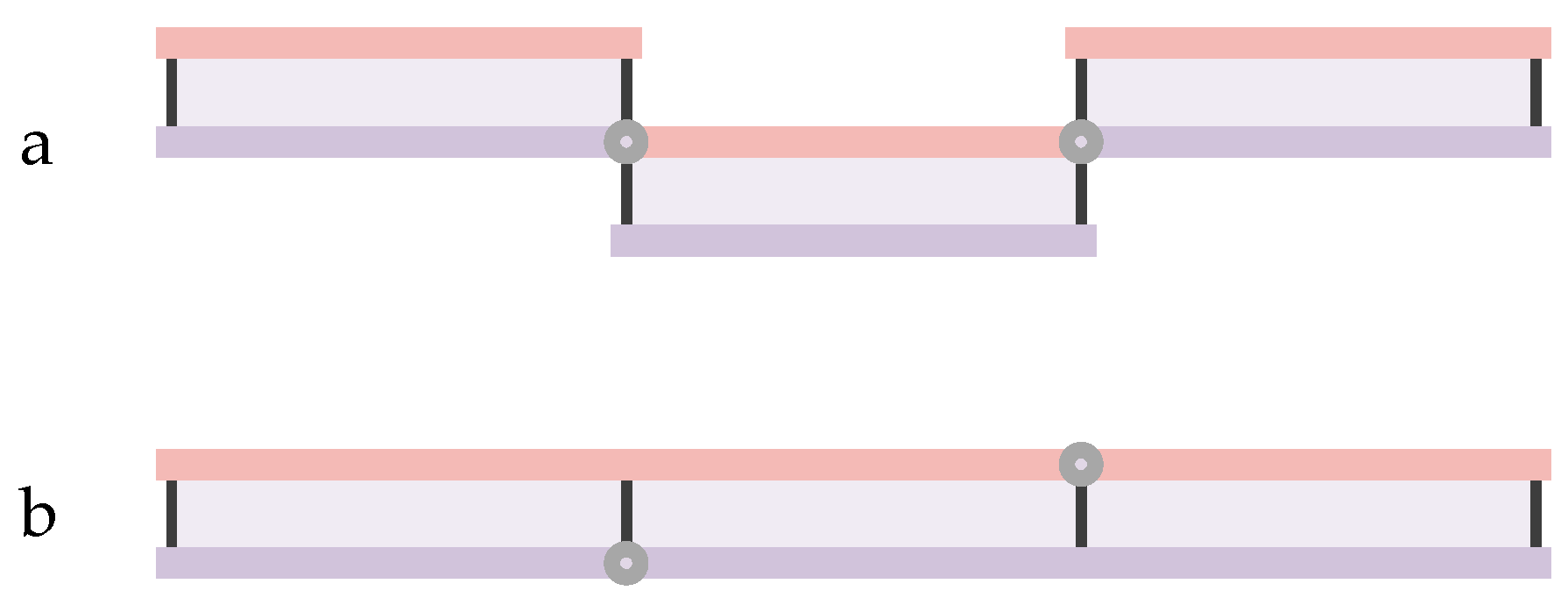
In the simple Z-shaped folding, mountain and valley folds alternate, and the folded state appears as shown in
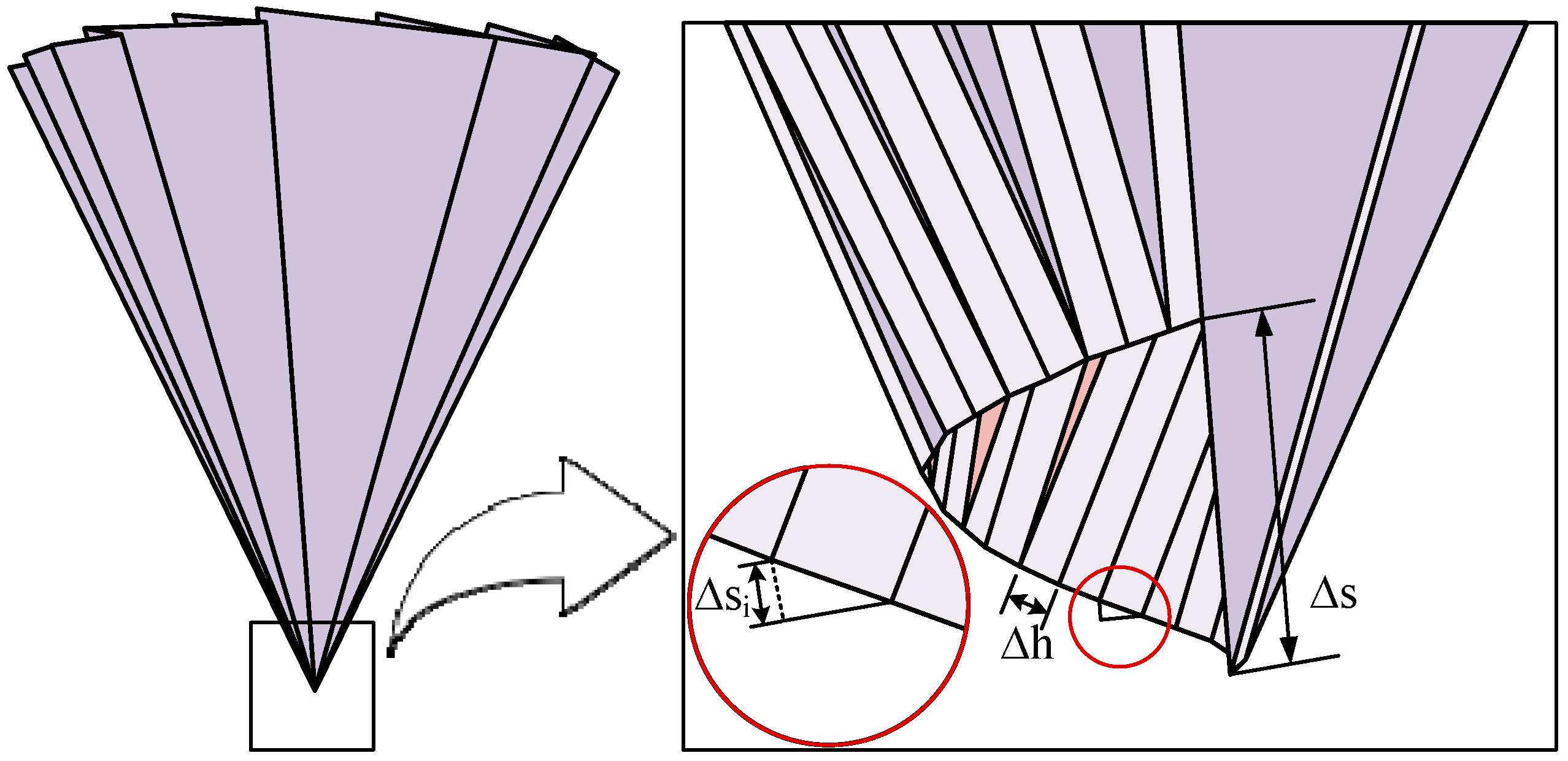
Figure 2. However, applying this folding method directly to curved surfaces introduces vertical offsets ∆h at the crease vertices, resulting in upward spiral displacements ∆S at the connections, as shown in
Figure 3. These displacements prevent the origami pattern from forming a closed loop at crease rotation angles between 0° and 180°. The total offset equals the sum of the individual offsets
from each origami unit. To achieve a closed-loop structure, axial displacements must be incorporated into the design of Z-shaped folds. This adjustment adds complexity to the structure.
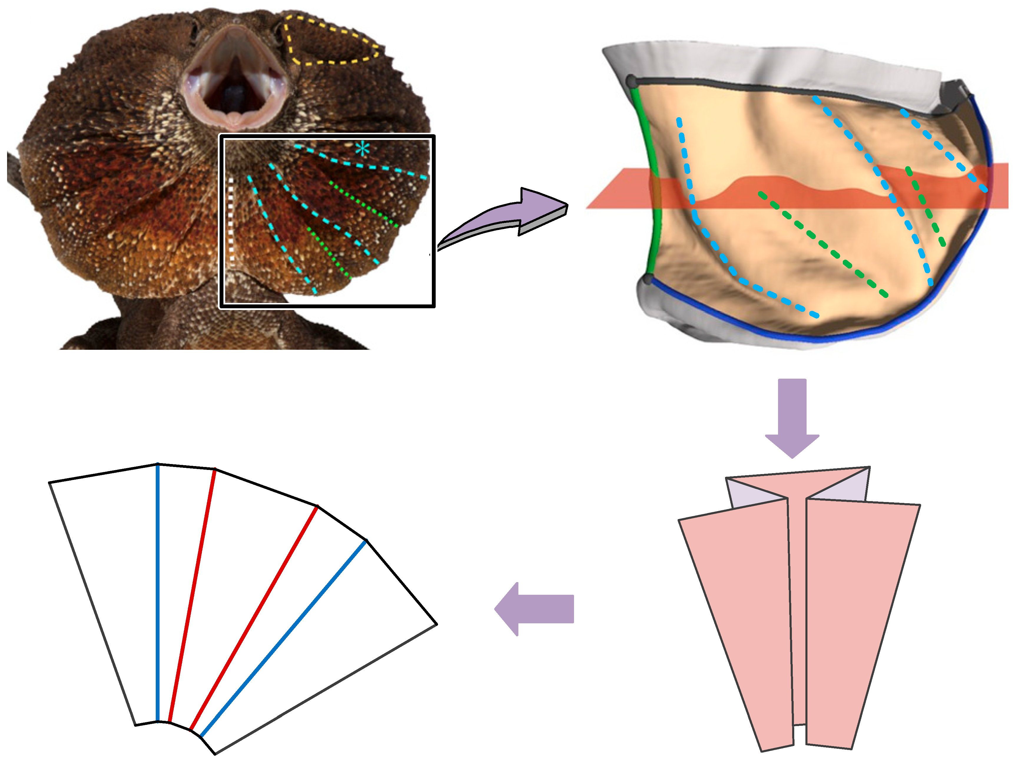
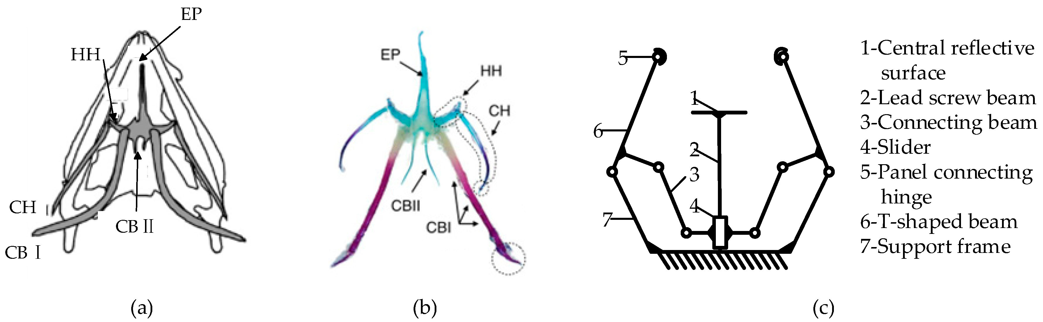
In nature, structures with significant thickness can also fold and unfold curved surfaces effectively. The frill of the frilled lizard serves as a prime example. Unlike the linear venation in insect wings, the frill’s surface features wrinkles with three ridges forming on each lobe of the fringe. Research from [
45] indicated that these ridges arise from elastic instabilities during the development of the branchial ectoderm, a result of natural selection.
When the frilled lizard folds or unfolds its thick frill, the distribution of mountain and valley folds becomes more complex than a simple Z-shaped folding, which shown in
Figure 4. The structure adds more folds, forming a mirrored arrangement of two Z-shaped folds, termed here as the Ω-shaped folding unit.
As shown in
Figure 5, this closed deployable structure consists of three types of facets, named facet1, facet-2, and facet-3, arranged according to their increasing facet angle. An Ω-shaped folding unit comprises two facet-1s, one facet-2, and one facet-3.
In the Ω-shaped folding unit, the distribution of creases in the sub-unit origami pattern changes from “mountain-valley-mountain-valley” to “mountain-mountain-valley-valley”. When the first Z-shaped unit of the Ω-shaped folding unit generates an upward offset of length , the second Z-shaped unit, which is mirror-symmetrical to the first, generates a downward axial offset of length . After the offsets of the two Z-shaped sub-units cancel each other out, the total offset of the Ω-shaped fold is zero, meeting the requirement for sub-unit connection into a ring.
2.2. Determination of the Number of Origami Units
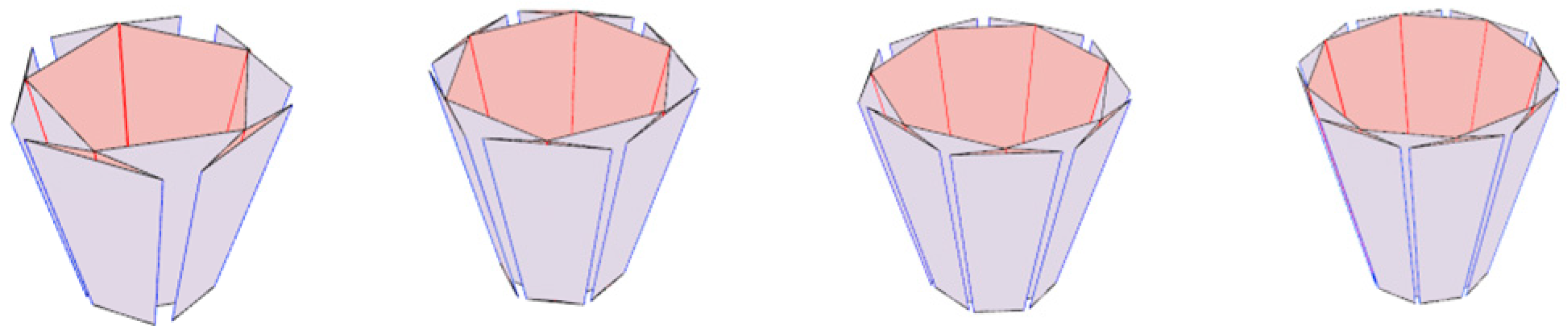
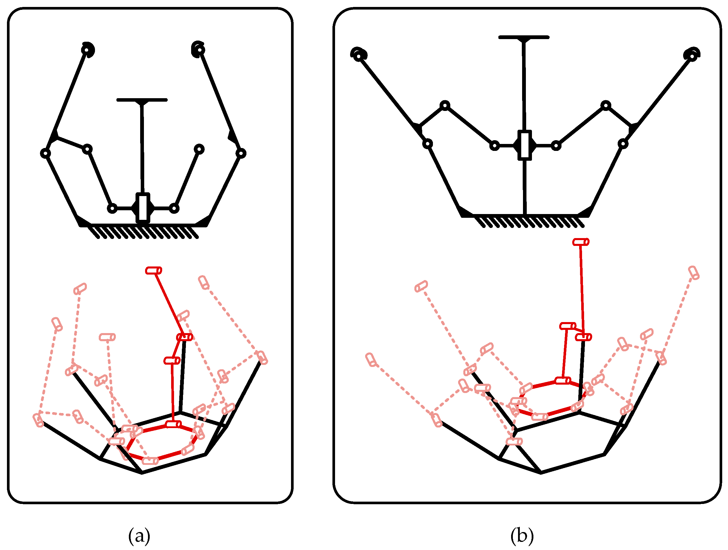
When designing a complete crease pattern starting with Ω-shaped units, several factors require consideration for mathematical analysis and optimization. The number of Ω-shaped units is a critical aspect. Evaluating this number involves assessing the folding ratio, manufacturing complexity, and structural reliability. The choice of unit count directly influences deployment performance and must take priority in the design as shown in
Figure 6.
To simplify analysis, assume each unit transforms from a plane into a truncated polyhedron during folding. At least three Ω-shaped units are needed to create a continuous closed-loop structure. In the engineering application of space antennas, besides forming a closed-loop structure, the folding ratio is also an important reference factor. Folding ratio is a key metric for measuring the antenna’s foldability and portability. It is defined as the ratio of the antenna’s radial dimensions in the folded state to those in the deployed state. A lower folding ratio means the antenna takes up less space when folded, making transportation easier and reducing the cost. Calculations show that the folding ratio increases with the number of units and approaches 0.25 as the unit count approaches infinity.
The design must also consider the impact of the smallest facet angle on manufacturing precision. Extremely small angles increase production and assembly challenges, raising costs and reducing reliability. Designs should avoid excessively small facet angles. Based on the relationships between unit count, folding ratio, and minimum facet angle, results indicate that the unit count should remain between 3 and 10. Fewer than 3 units are insufficient to form a continuous closed-loop structure, while more than 10 units greatly increase manufacturing and assembly challenges without significant gains in folding ratio performance.
Additionally, the number of facets significantly affects complexity and reliability. Adding more facets introduces additional hinges and panels, increasing structural complexity and internal gaps while reducing reliability. Assuming each crease connects through two hinges, a relationship between unit count and hinge count emerges.
Analysis of these factors leads to several conclusions. The foldability ratio decreases with increasing unit count, with the rate of change slowing around seven units. Similarly, changes in the smallest facet angle also slow at this point. Furthermore, component count increases linearly with unit count.
Table 1 illustrates these trends for different unit numbers.
The final determination of the unit number is affected by several factors. Each of these factors has a varying level of impact. To address this complexity, the Analytic Hierarchy Process (AHP) is introduced as a comprehensive evaluation system. This system will assess the influence weight of each factor on the final number of units. In the hierarchical analysis, we constructed a two-by-two comparison matrix for each of the three indicators and determined the relative weights of each item according to the importance of expert scores or design requirements. Specifically, a judgment matrix (a table comparing factors in pairs) is constructed using the 1–9 scale (e.g., 1 = equal importance, 9 = extreme dominance of one factor over another). The importance of each factor is determined according to the design requirements set by the launch vehicle’s payload constraints. Pairwise comparisons are used to create the evaluation matrix
, as follows:
where
quantifies the relative importance of criterion
over
.
Then, normalized weights matrix
are calculated through eigenvector analysis:
where
, while
quantifies the relative importance of criterion
over
.
Subsequently, the normalised weights of the criteria were derived by solving the eigenvector associated with the maximum eigenvalue
of the pairwise comparison matrix
. To validate the logical consistency of the expert judgments, the consistency ratio (CR) was calculated as:
where
,
n = 3 (number of criteria), and
RI = 0.58 (the random consistency index for a 3 × 3 matrix, obtained from standardized AHP reference tables).
The consistency ratio in this study is about 0.051, which is much lower than the common threshold of 0.1, indicating good internal consistency in weight assignment. As shown in
Table 2, foldability receives the highest normalised weight (0.6551) in the overall trade-off, indicating that it is crucial to the optimization of the folding unit. Meanwhile, the number of facets and the maximum sector angle are 0.2114 and 0.1335, respectively, reflecting the need to take into account the degree of simplification of the structure and the machining feasibility while satisfying the need for folding. This quantification process helps determine the importance of each design goal and provides a clear way to improve the folding unit. The AHP method ensures a fair and structured evaluation, allowing us to balance different factors and choose the best design based on the data.
To summarize the influence of each factor, the weighted scores were calculated and compiled into
Table 3. It combines information from
Table 1 and
Table 2 to calculate the final scores.
Table 1 lists the influence factors, such as folding ratio, minimum facet angle, and number of facets, while
Table 2 provides their importance weights. In the current evaluation system, these influence factors are adjusted to a 1–10 scale for easy comparison. For parameters where smaller values indicate better performance (such as folding ratio and number of facets), higher scores are assigned to lower values. Conversely, for the minimum facet angle, where a larger value is preferable, the scoring is reversed. This ensures that higher scores always indicate better performance.
After obtaining the normalized score for each factor, the final weighted score can be calculated by summing the weighted contributions based on the weights listed in
Table 2.
Table 3 presents the relationship between the number of units, folding ratio, and final weighted score. The folding ratio decreases as the number of units increases, but the weighted score varies due to the trade-offs between different factors. The highest score is observed at six units, suggesting an optimal balance based on the current evaluation system.
2.3. Dimensional Analysis and Optimization of Single-Vertex Multi-Crease Origami Patterns
The previous discussion covered the impact of unit quantity on SVMCO patterns. In addition, the angle proportions between facets1, facets2, and facets3 are also crucial factors to consider when designing crease patterns. By adjusting the angle proportions, the structure can be modified to find the optimal folding ratio. This process not only affects the overall shape of the origami pattern but also directly influences its functional performance and practical application.
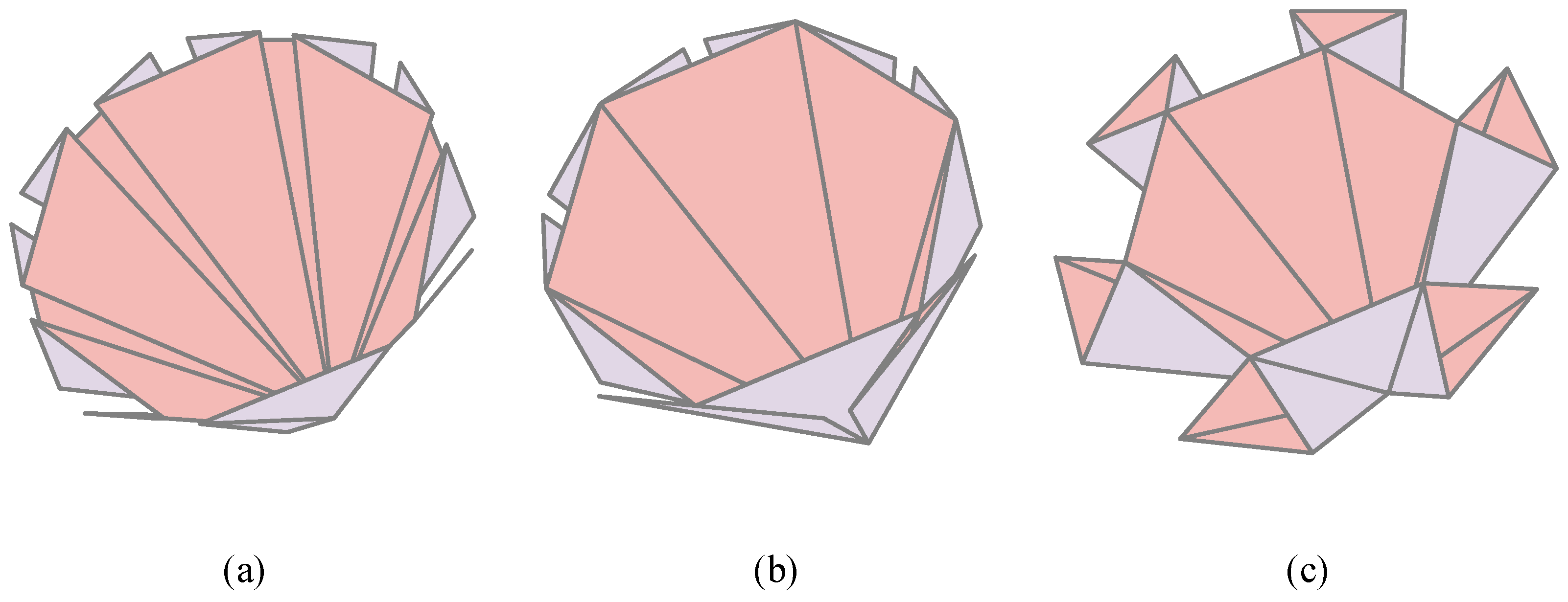
By observing the projected shapes with the maximum projection area, it can be found that adjusting the angle proportions between facets1, facets2, and facets3 results in three different states, as shown in
Figure 7. These three states not only exhibit noticeable visual differences but also demonstrate unique characteristics in practical applications. The calculation process for the folding ratio varies for each state, and these differences need to be considered and optimized in the specific design to ensure an optimal performance of the origami structure in different application scenarios. The following sections will discuss the three folding methods separately.
Let
denote the sector angle corresponding to facets1,
the sector angle corresponding to facets2, and α
3 the sector angle corresponding to facets3. Since there are 6 Ω origami units (
), each unit occupies an angle of 60°. Therefore,
When
, the folded state is shown in
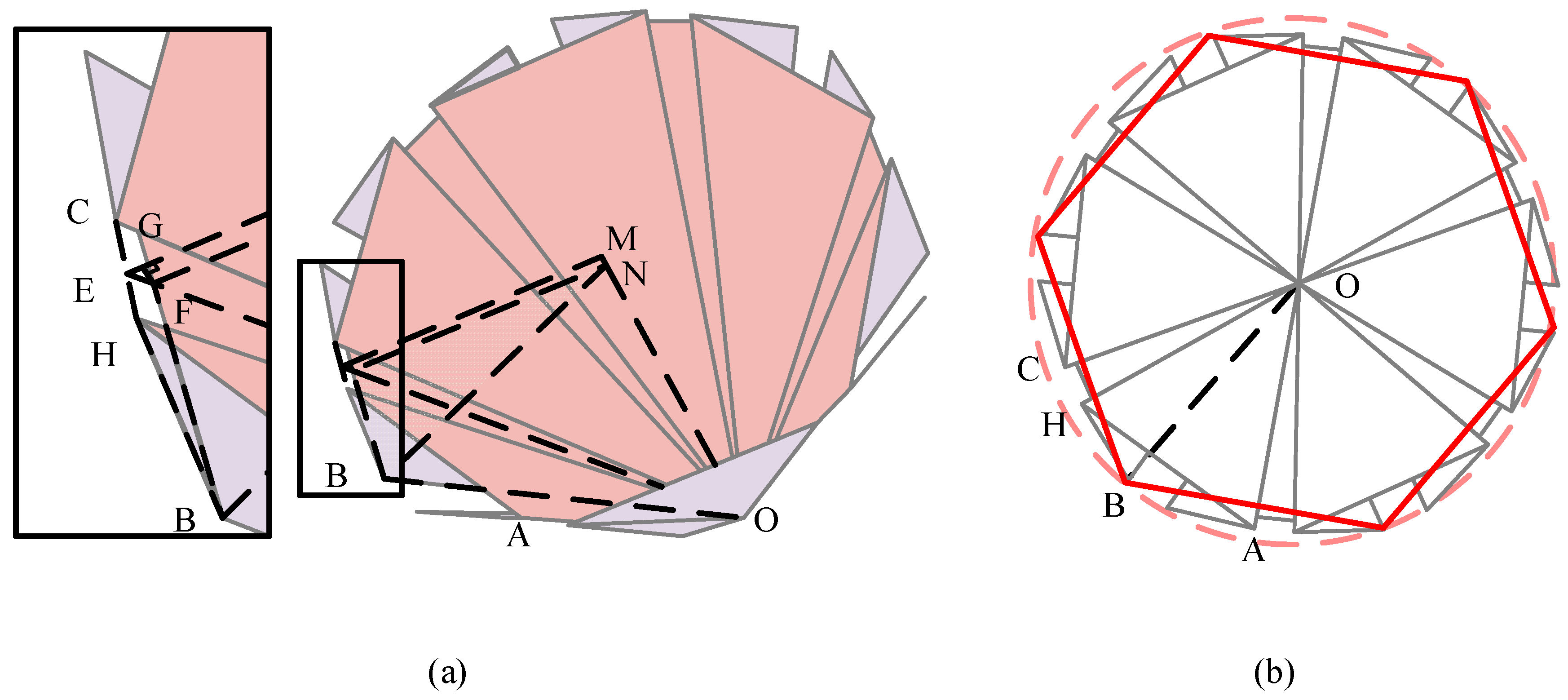
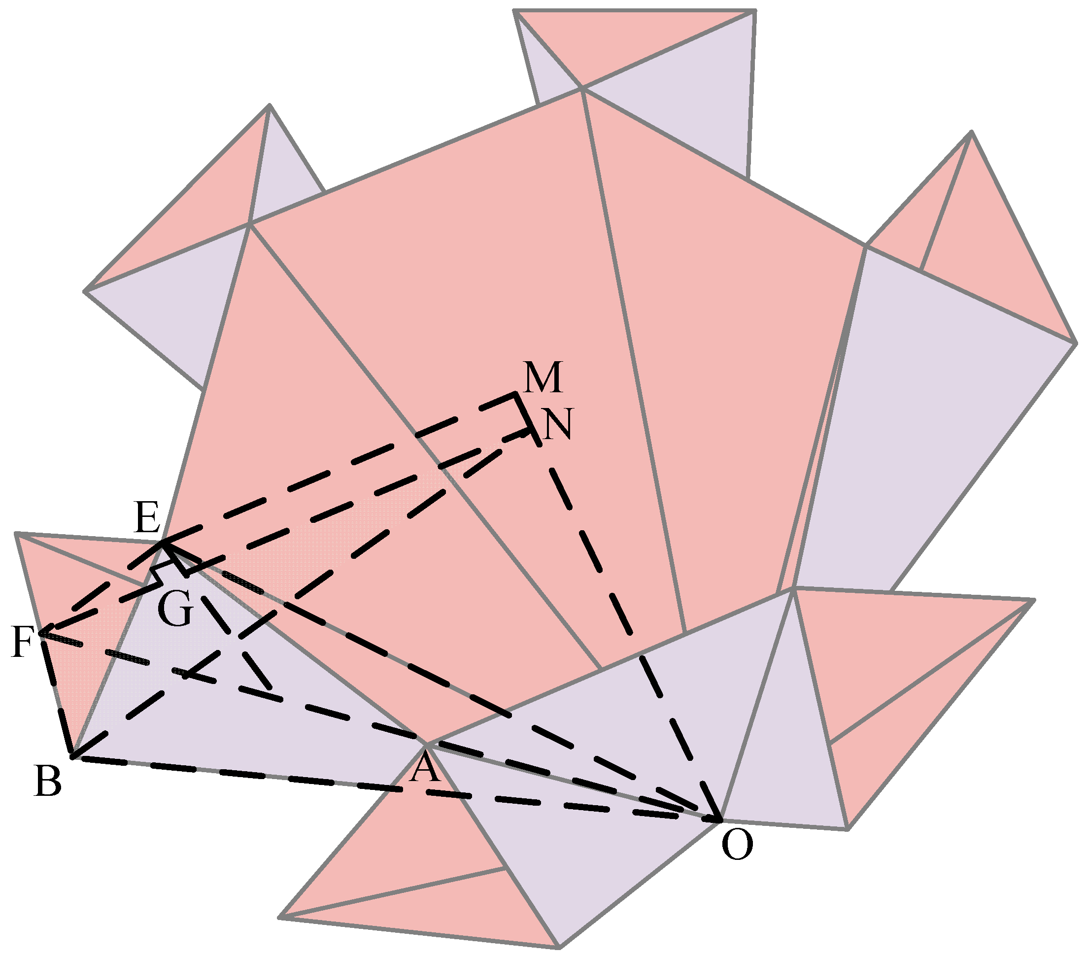
Figure 8a, and the radius of the outer circle of the origami pattern is r.
Figure 8b presents a top view of this structure, which shows that the shape’s circumscribed circle is formed by a regular hexagon. The fully compacted radius equals the distance between these vertices and the hexagon’s centre. The hexagon vertices originate from the farthest points of facet-3 in each unit. As shown in
Figure 8b, the maximum circumscribed circle of the shape has its point of displacement at point B. By measuring the displacement of point
B and its distance to the central axis, denoted as the length
NB, the folding ratio of this origami pattern can be determined.
The folding ratio,
n, is defined as the ratio of the distance from a vertex on the envelope polygon to the centre of the structure to the radius
. It is calculated as:
Among
where
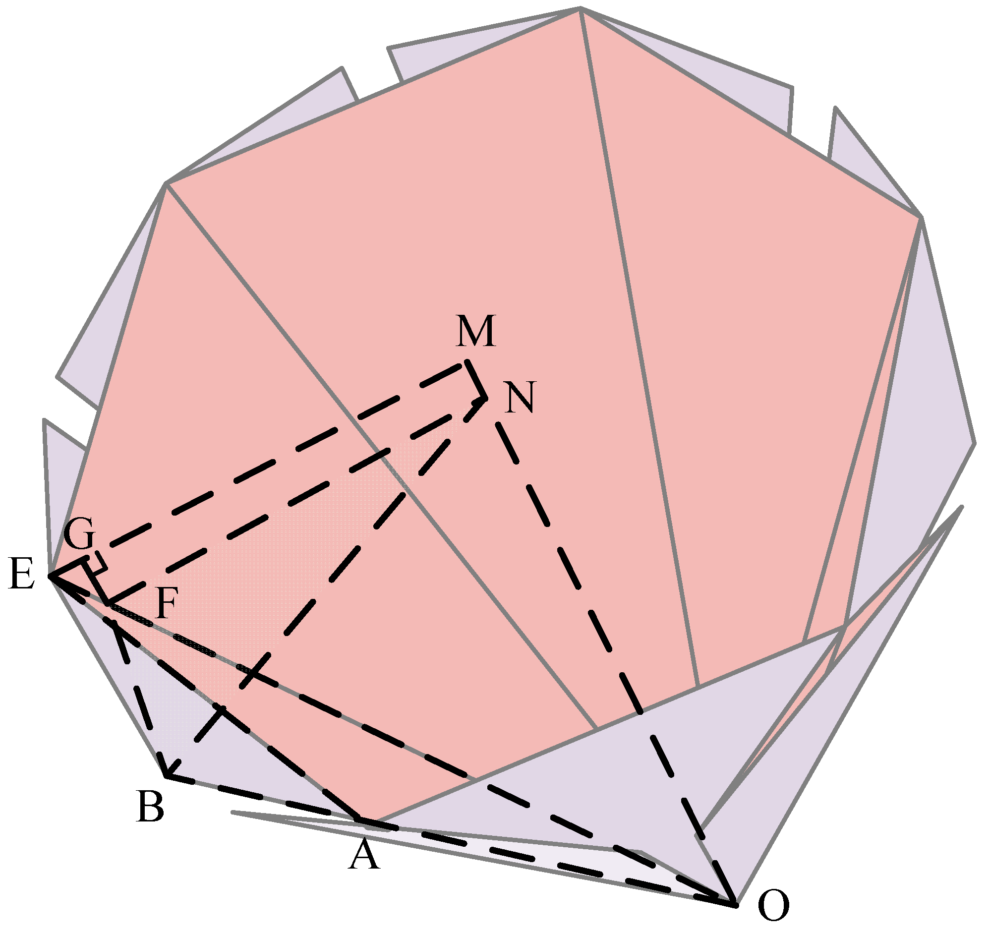
. The final folding state is shown in
Figure 9, and the outer circle radius of the origami pattern is also set to
. Because the ratio of the fan angle between the panels changes, point
C, point
H, and point
E overlap, and the overlap point is denoted by point
E.
The folding ratio,
n, is defined as the ratio of the distance from a vertex on the envelope polygon to the centre of the structure to the radius
r. It is calculated as:
When
, the final folded state is shown in
Figure 10. Let the radius of the outer circle of the origami pattern be
, in addition, the long edges of the adjacent facet-2 after folding are coincident, and the short edges points of facet-2 coincide at point E.
The distance from a vertex on the envelope polygon, formed after folding, to the centre of the structure is
To determine the impact of angle division on the folding ratio of the panels, this paper will follow the calculation and analysis process outlined in
Figure 11. First, we designed the initial conditions and input the sector angle ranges for facet-2 and facet-3. For every 0.25° increment, a set of sector angle data will be generated, and the corresponding sector angle for facet1 will be calculated. The program first verifies whether the sector angle data sets and the corresponding sector angle for facet1 are within the acceptable range to ensure that the total sector angles for one unit sum to 60°. Next, it checks for interference by determining if
exceeds 60° and if
is greater than
. The condition
signals that adjacent facets might overlap, while
confirms that the overlap is significant. These dual checks help ensure a smooth, interference-free folding process. If any of these constraints are met, the input data set for the sector angles is marked as invalid and the program moves to the next data set. Otherwise, one of the three predefined calculation methods is selected based on the proportional relationships to calculate the folding ratio. Finally, all valid results are output, and a graph is generated to represent the relationship between the input sector angle data sets and the folding ratio.
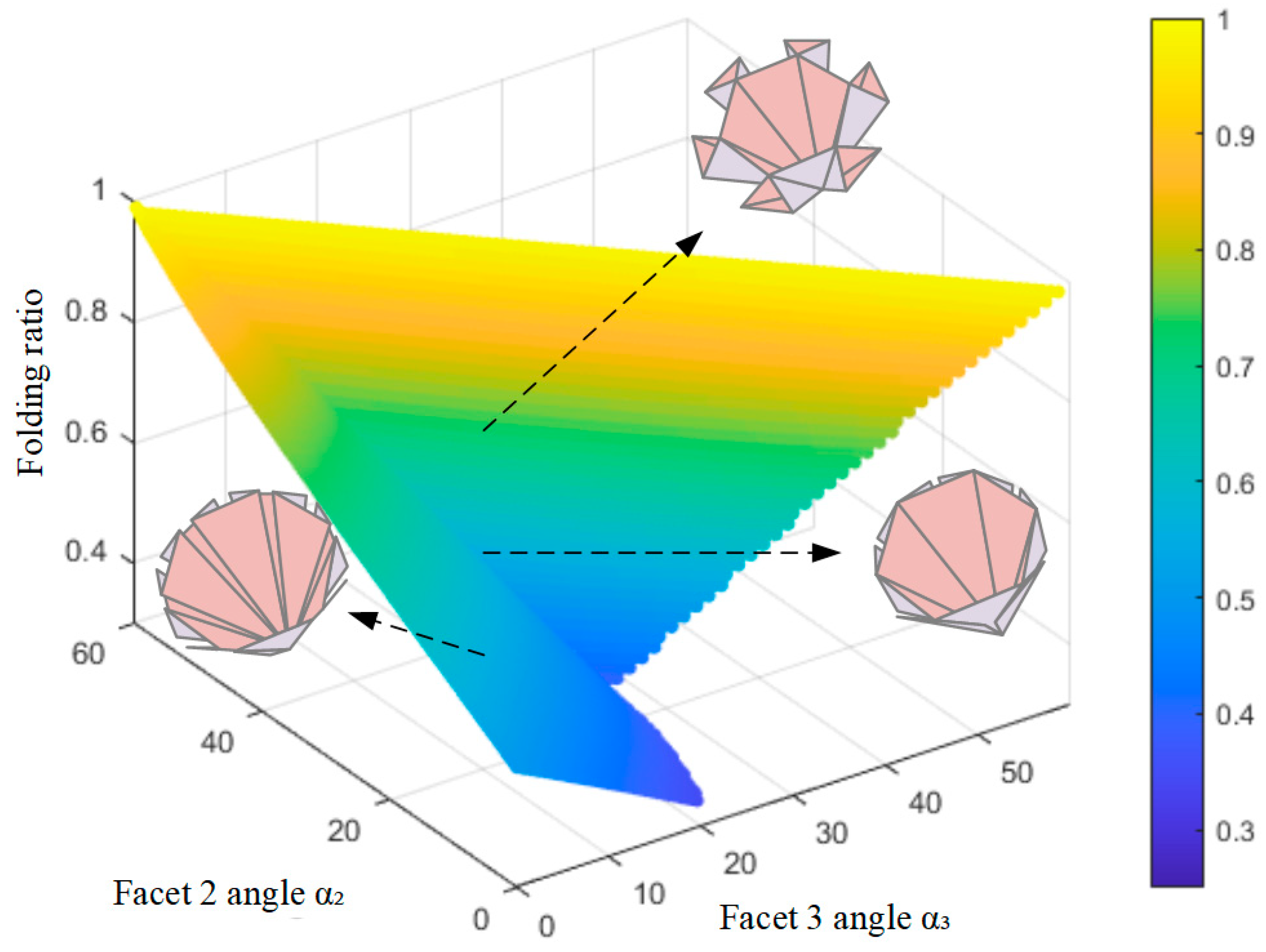
Figure 12 illustrates the relationship between facet angles (
on the x-axis, α
3 on the y-axis) and folding ratio, represented by color (blue: low, yellow: high). Under the geometric constraint
,
is determined once
and α
3 are selected. Two clear trends emerge:
Increasing consistently raises the folding ratio (the colour shifts toward yellow).
Increasing α3 initially increases the ratio but eventually lowers it, forming a low value along the line .
Figure 12.
The relationship between facet-2 angle , facet-3 angle , and folding ratio.
Figure 12.
The relationship between facet-2 angle , facet-3 angle , and folding ratio.
The darkest blue region (optimal folding ratio) aligns precisely with , where the ratio reaches its minimum. Designs left of this line () show higher ratios (blue–green transition), while those to the right () also underperform (blue–cyan transition). This confirms as the optimal configuration for the minimizing folding ratio, which we adopted in the thick-panel model to maximize storage efficiency.
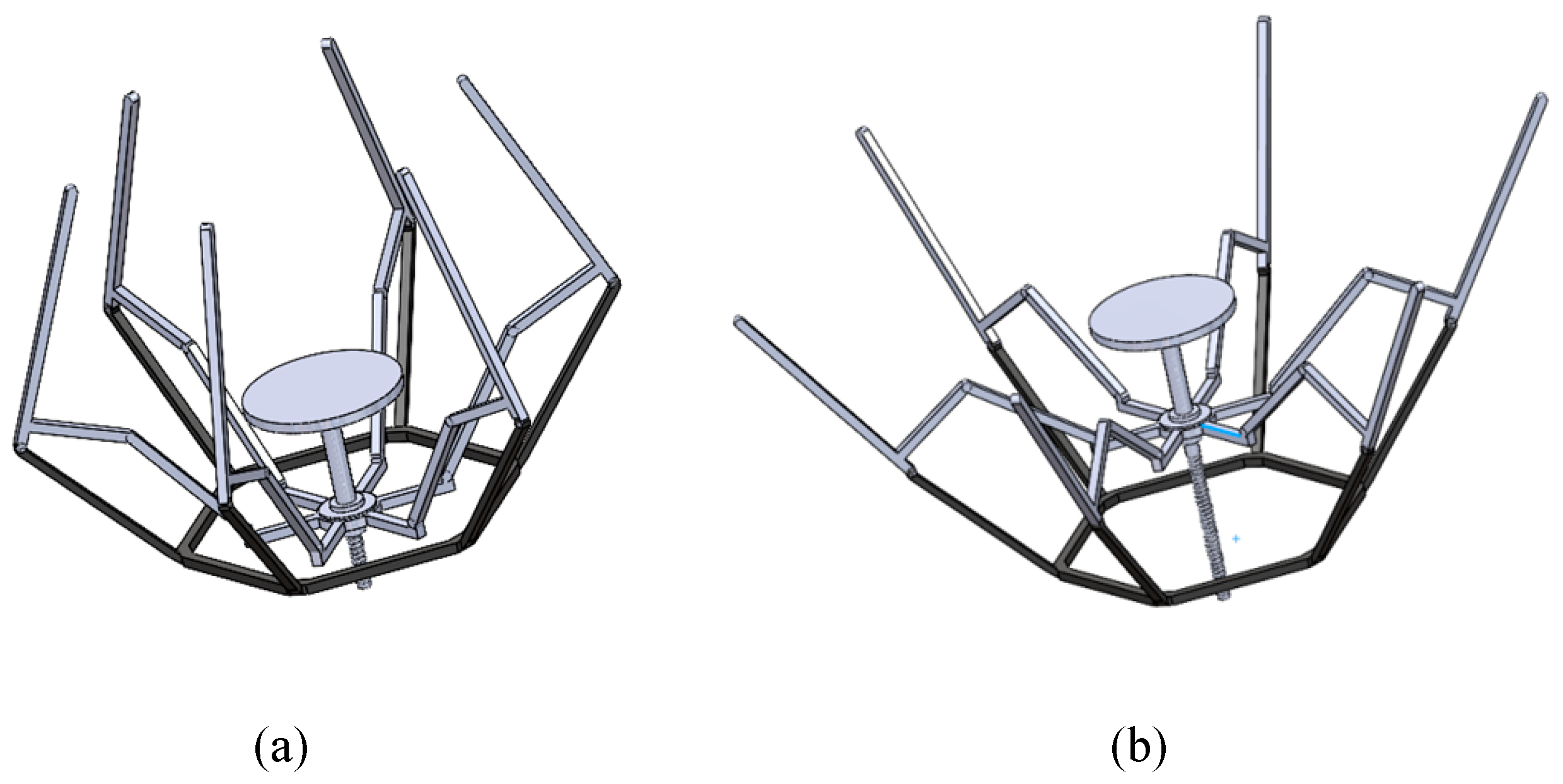
4. Prototype Design and Analysis
This section will evaluate the prototype developed based on the thickened SVMCO model and compare the theoretical and actual folding ratios as shown in
Figure 18. The model was designed with a thickness-to-radius ratio of 3:50. The panel itself is a circular ring with an outer diameter of 1.5 m and an inner diameter of 0.3 m. A physical prototype was then fabricated. The theoretical analysis calculated the folding ratio of the thickened origami pattern model to be 0.51. In contrast, prototype testing showed an actual folding ratio of 0.54, determined through manual measurement of the envelope diameter, which is slightly higher than the predicted value.
The difference between the calculated and actual folding ratios can be attributed to several interconnected factors.
First, manufacturing tolerances may lead to minor deviations in fold angles and facet dimensions, affecting the folding ratio. Additionally, variations in material properties from theoretical assumptions can result in inaccuracies. Furthermore, hinge and joint friction, which are not fully considered in the models, can introduce resistance in the prototype and hinder smooth deployment.
Despite these discrepancies, the close match between the theoretical folding ratio (0.51) and the actual folding ratio (0.54) suggests that the design principles of the thickened origami pattern model are sound.
The result shows that the model effectively creates deployable structures with favourable folding ratios and reduced support requirements, with the prototype tests validating its potential for practical applications.
5. Conclusions
This research explored the design and optimization of single-vertex multi-crease origami (SVMCO) patterns, resulting in a deployable structure with improved efficiency.
The analysis examined how the number of units in a single-ring array impacts the folding ratio, revealing that an array with six units achieves the optimal balance between compactness and structural efficiency. A mathematical model linked facet sector angles to folding performance, identifying that the optimal folding ratio occurs when the minimum facet sector angle is half the maximum.
This model also accounted for panel thickness, inner diameter, and outer diameter to determine the best design for given parameters. Inspired by bionic principles, the study introduced a rib support system mimicking natural structures, enhancing stability and usability. A prototype with a 1.5 m radius validated this design, showcasing a theoretical folding ratio of 0.51 and an actual folding ratio of 0.54.
The structure demonstrated high deployability, reduced support requirements, and a smooth reflective surface. These findings contribute to deployable structures with practical applications and inspire further research into bionic-inspired designs and advanced engineering implementations.
Future work will focus on extending this planar structure to curved surfaces, which is critical for applications such as deployable antennas. Key challenges include the design of specialised hinges to accommodate curvature and the development of thick-plate origami techniques to address material thickness limitations. Advancing work in these areas will improve the structural integrity and functionality of deployable systems in aerospace and communications applications.


