Abstract
Although robots are increasingly expected to perform inspection tasks in three-dimensional ferromagnetic structural environments, magnetic-wheeled climbing robots face significant challenges in overcoming obstacles and transiting between planes. In this paper, we propose a novel bicycle-like magnetic-wheeled climbing robot, named BiMagBot, featuring two magnetic wheels that allow the adaptive adjustment of magnetic adhesion without the need for active control. The front wheel incorporates an arc tentacle mechanism that rotates a ring magnet to adjust the magnetic adhesion, while the rear wheel uses an eccentric shaft-hole design to facilitate a smooth transition of magnetic adhesion between surfaces. The magnetic forces acting on both wheels during transitions through concave corners were analyzed and discussed via simulations to elucidate the underlying principles. A prototype of the robot was developed and tested experimentally. The results show that the front and rear wheels can adjust the magnetic adhesion during the transition of corners with angles ranging from 90° to 315°. The robot only weighs 1.6 kg, but it can carry a weight of 2 kg with a speed of 0.9 m/s to transit across concave corners, demonstrating comprehensive capabilities in plane transition, ease of control, and load capacity.
1. Introduction
Magnetic-wheeled climbing robots are commonly recognized for their high mobility and strong load-bearing capacity, making them ideal for climbing ferromagnetic structures such as ship hulls [1], container shells [2], bridges [3], and wind power towers [4]. However, the three-dimensional complex environment demands that these robots exhibit exceptional environmental adaptability, particularly in navigating through diverse convex and concave corners, thereby expanding their operational range.
Traditional magnetic-wheeled climbing robots are typically designed by incorporating magnetic mechanisms for wall adhesion with ground robot configurations [5,6,7]. Although these robots are straightforward in design, their limited adaptability makes them unsuitable for carrying out tasks in intricate geometries.
To address this challenge, Nguyen S. T. developed a bicycle-like climbing robot with a degree of freedom at the waist. The robot can transit concave and convex corners with angles ranging from 90° to 360° [8]. Similarly, Sirken A. et al. designed a climbing robot equipped with a flexible waist, allowing for the adjustment of the distance between the front and rear wheels to transit concave or convex corners with angles ranging from 45° to 340° [9]. However, when the magnetic wheel’s adhesion is excessive, significant driving force is required to overcome resistance at the concave corners, often reducing the robot’s speed. Conversely, insufficient adhesion force would reduce the robot’s load capacity, leading to risks such as slippage or detachment. Fabien T. et al. proposed a bicycle-like climbing robot incorporating lever-arm mechanisms on both the front and rear wheels [10]. This design employs lever arms to detach the robot from the adhered surface, facilitating the transition of concave corners. Eto H. et al. developed a robot with rotatable magnetic adhesion mechanisms [11]. This design incorporates fan-shaped magnetic components that can adjust their rotation angles to redistribute the magnetic force, thereby facilitating to transit concave or convex corners. However, both robots require the precise control of either the lever-arm or magnetic adhesion mechanisms based on the size of the angle being transited. In scenarios that require the robot to transit concave or convex corners frequently or where the angles are unknown, this operational requirement becomes highly inconvenient.
Legged climbing robots [12,13] are known for their strong capabilities of transiting obstacles. However, they often come with limitations such as low load capacity and relatively large size, making them unsuitable for operation in confined spaces. Hybrid wheel/track-leg climbing robots [14,15,16] and multi-module hybrid-configuration robots [17] also exhibit exceptional capabilities of transiting obstacles. Nevertheless, these designs face challenges such as complex structures, large size and weight, and intricate control systems.
In this study, we present a new magnetic-wheeled robot design to enhance the plane-transition capabilities and reduce the operation complexity. The main contributions of this study can be summarized as follows:
- An innovative front wheel module was designed, whose unique tentacle mechanism passively rotates the ring magnet when passing through the concave corners, thereby achieving the switch of magnetic adhesion from one surface to another without any active control.
- A rear wheel module with an eccentric shaft-hole design was presented to facilitate smooth transition of magnetic adhesion between surfaces without active control.
- A bicycle-like climbing robot employing the front and the rear magnetic wheel designs was developed. The simulation analysis of magnetic adhesion force on both surfaces revealed the operational principle of the design during the transition process. Experiments demonstrated the robot’s excellent comprehensive capabilities in terms of plane-transition, ease of control, and load capacity.
2. System Development
2.1. Robot System
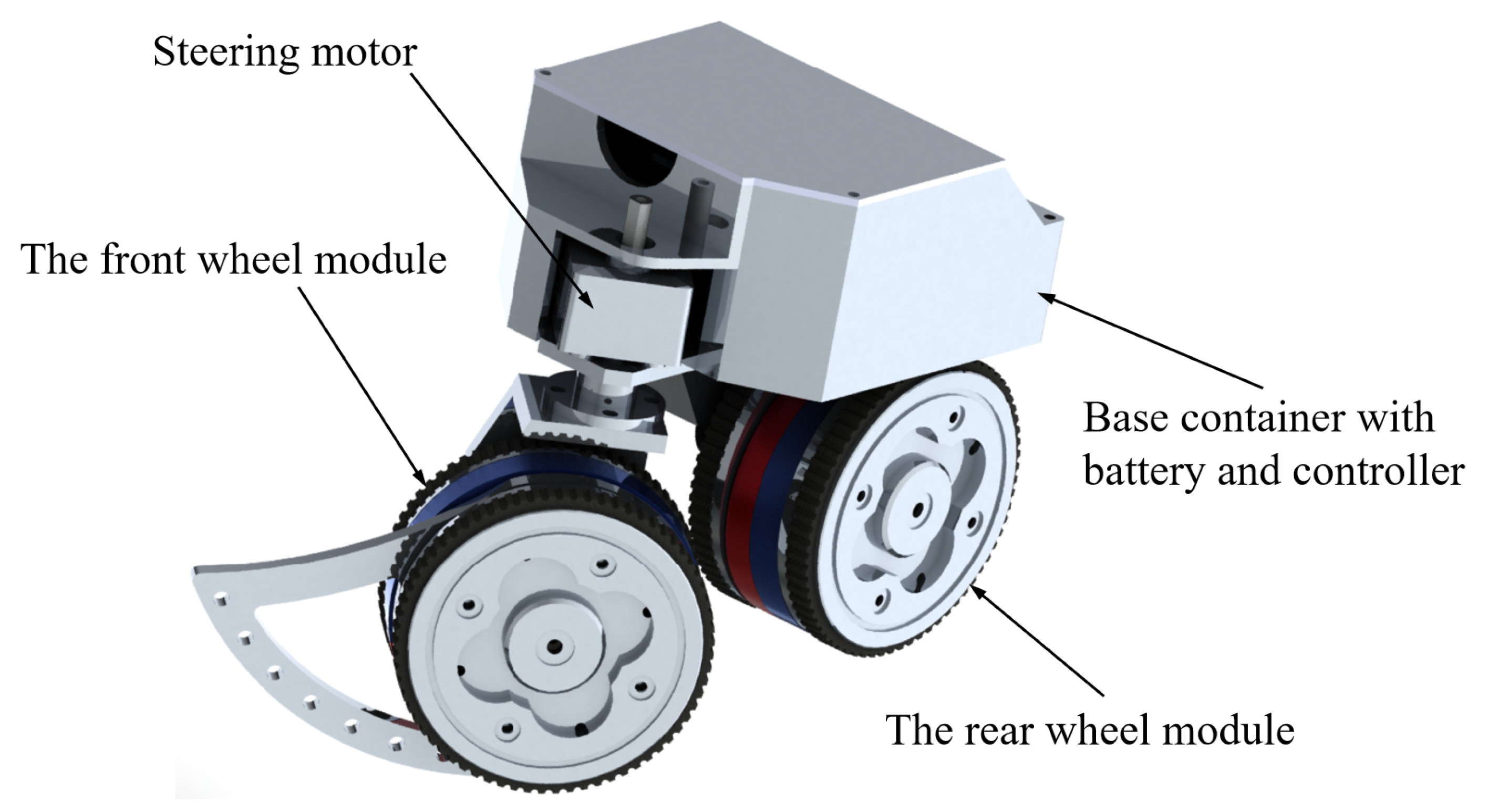
Figure 1 depicts the structure of the proposed bicycle-like magnetic-wheeled climbing robot (BiMagBot). The BiMagBot employs a bicycle configuration with three active drives, each dedicated to steering and the two wheels, respectively. This bicycle configuration facilitates mobility speeds up to 0.9 m/s and enhanced steering performance. To improve the robot’s capability in transitioning between planes, both the front and rear wheels incorporate a unique adaptive magnetic adhesion design, which will be elaborated on in the following sections. The BiMagBot is completely untethered, carrying Lithium batteries and a mini controller within its base container. Currently, it is remotely controlled by operators sending motion commends via a wireless communication with joysticks. Owing to the wide front and rear wheels, the BiMagBot achieves static balance without requiring dynamic balance control. The kinematics of this type of robot can be found at [8]. The primary technical specifications of the BiMagBot are presented in Table 1.

Figure 1.
Structure of the BiMagBot.

Table 1.
Technical specifications of the BiMagBot.
2.2. Magnetic Adhesion-Adaptive Front Wheel
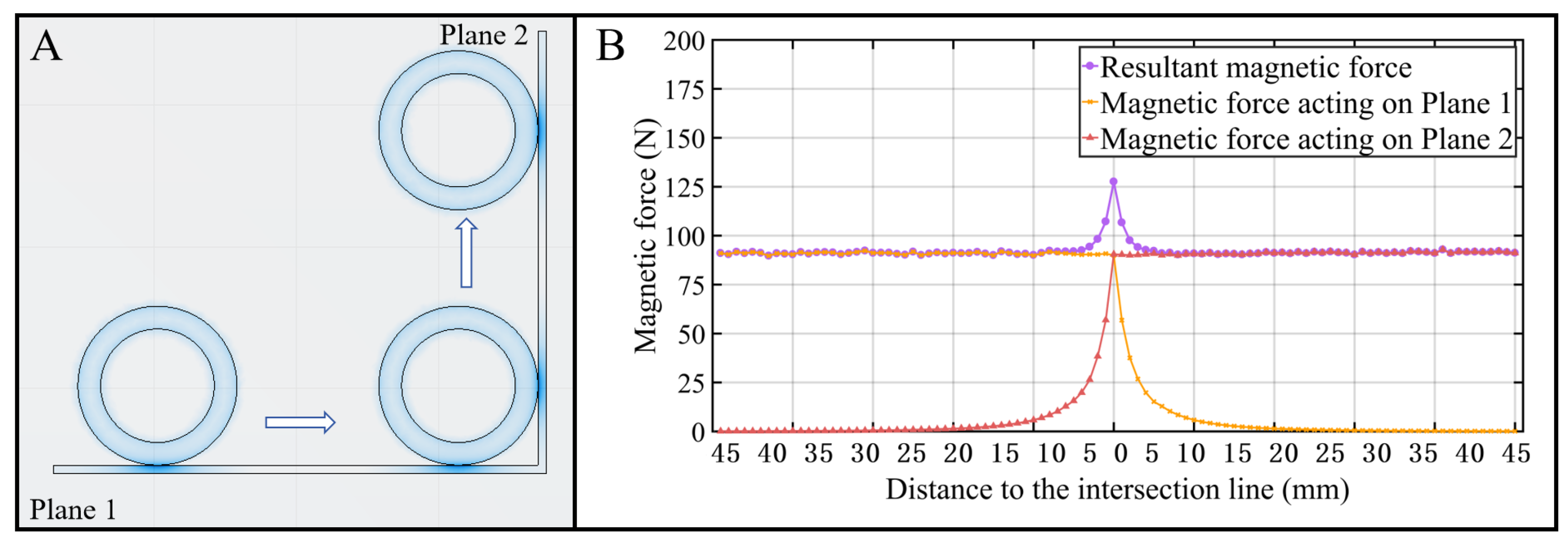
When a wheel equipped with a ring magnet as the adhesion component traverses a concave corner, transitioning from Plane 1 to Plane 2 as illustrated in Figure 2, the magnetic forces acting on the two planes undergo rapid changes and demonstrate an inverse relationship. Specifically, the magnetic force on Plane 2 increases rapidly from zero as the wheel approaches the intersection line, while the force on Plane 1 decreases sharply to zero upon the wheel crossing the intersection line. The resultant magnetic force from the corner structure initially increases, reaching a maximum value, then decreases and stabilizes. This increase in magnetic force indicates a trap for the robot in escaping from concave corners.
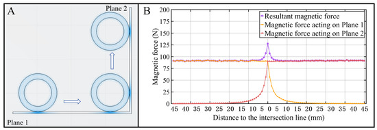
Figure 2.
The change in magnetic forces while a magnetic wheel traverses a concave corner. (A) Key positions during the transition. (B) The magnetic forces versus the distance to the intersection line of the corner, where the internal angle of the corner is 90° and the radius of the wheel is 40 mm.
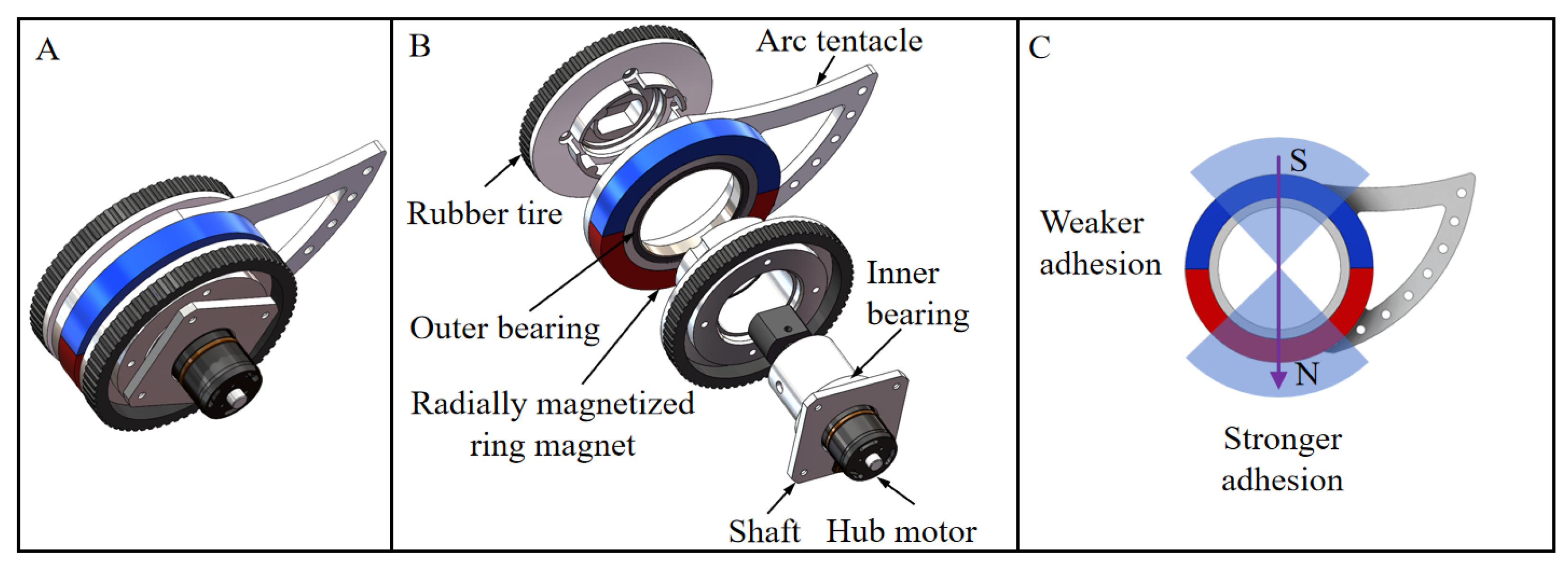
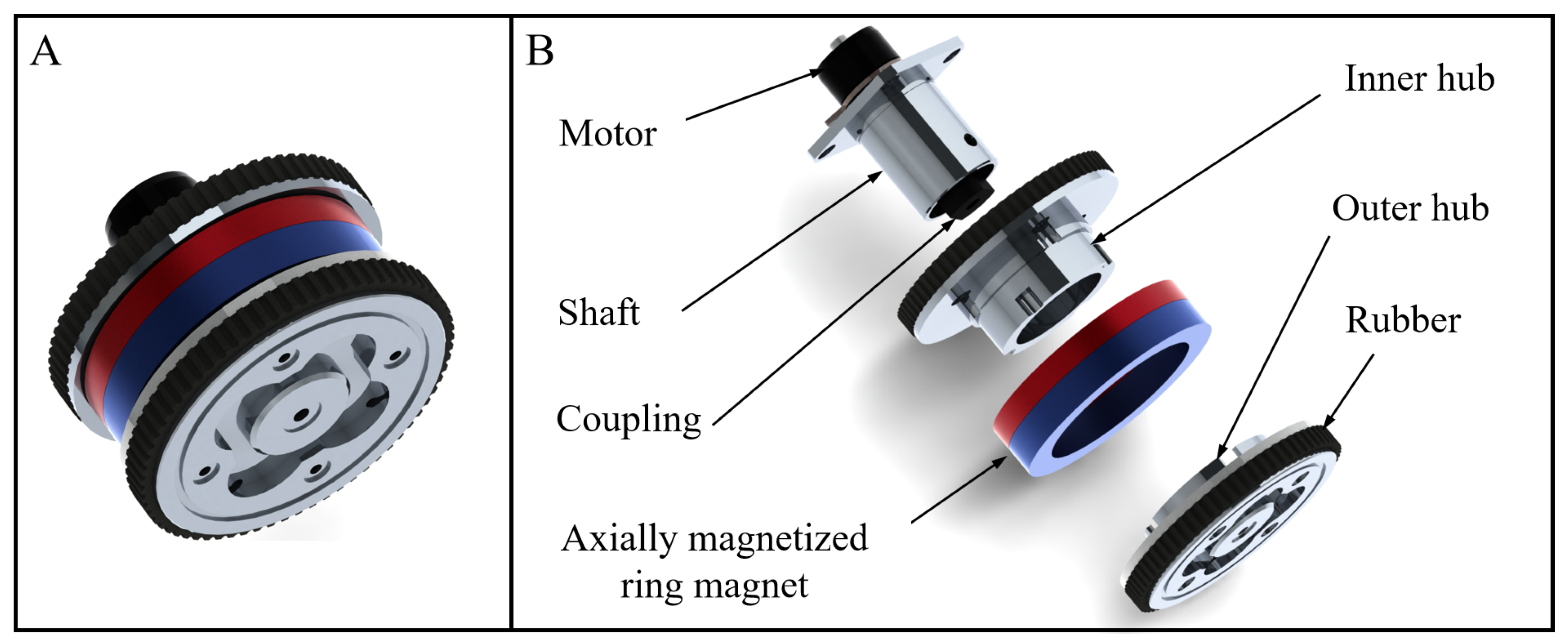
To overcome this limitation, an innovative front wheel module incorporating an arc tentacle mechanism is proposed in this study. As illustrated in Figure 3, the module comprises three key components: a hub motor, a tentacle–magnet assembly, and a rubber tire. The arc tentacle is mounted at the front end and firmly attached to the ring magnet, while maintaining rotational freedom around the wheel shaft. The ring magnet, characterized by radial magnetization, exhibits magnetic adhesion anisotropy, with stronger adhesion perpendicular to the magnetization direction and relatively weaker adhesion in other orientations. This unique configuration, combining a rotatable arc tentacle with a radially magnetized ring magnet, facilitates the early reduction in magnetic force on Plane 1 while simultaneously promoting the premature increase in magnetic force on Plane 2. Table 2 summaries the technical parameters of the front wheel module designed in this study.
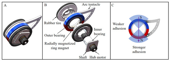
Figure 3.
Structure of the magnetic adhesion-adaptive front wheel module. (A) Assembly view. (B) Expanded view. (C) Magnetic adhesion anisotropy.
Table 2.
Technical parameters of the front wheel module.
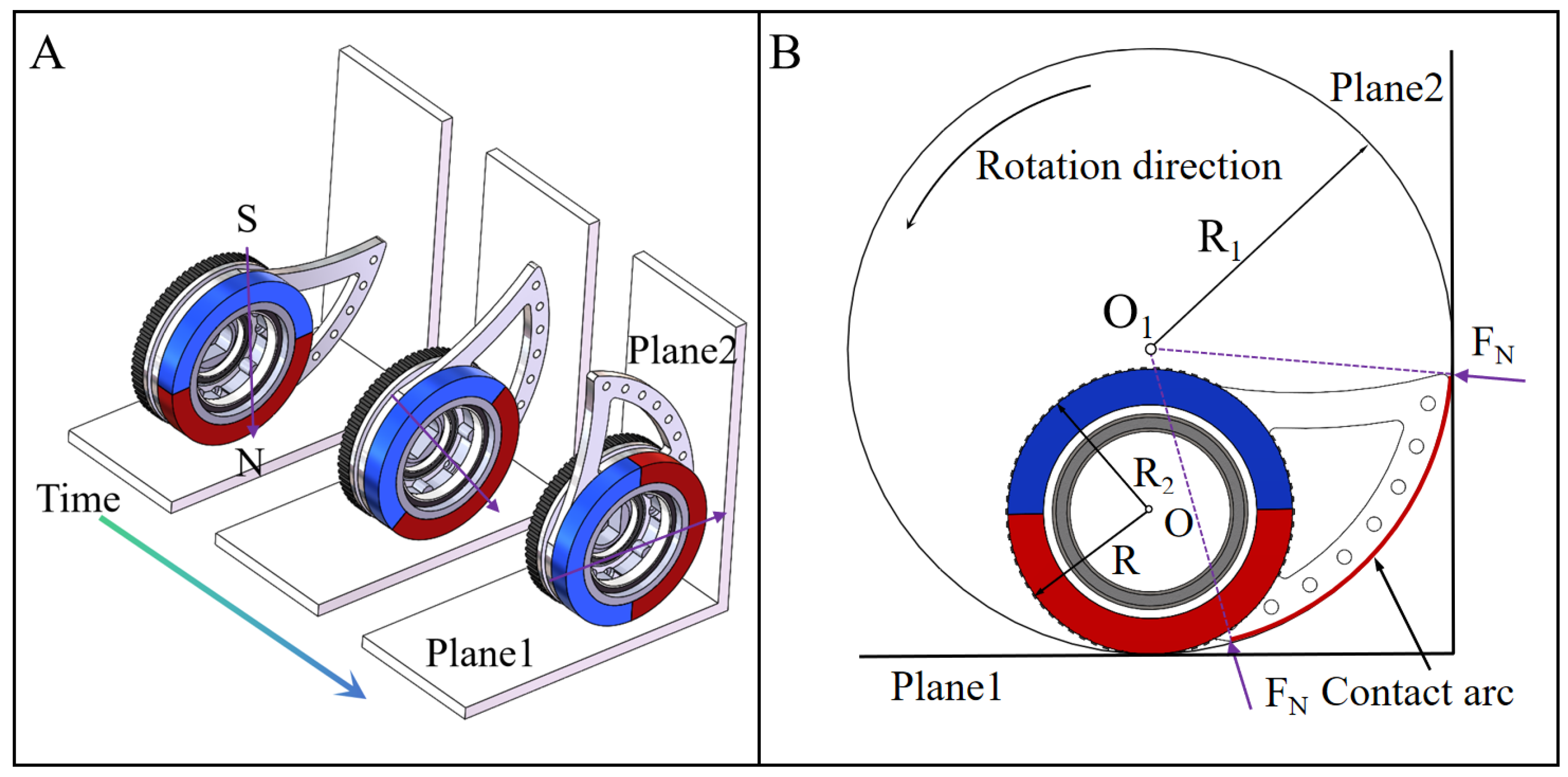
Figure 4 details the operational principle of the front wheel module. When the wheel module moves along Plane 1 at a distance from the intersection line (with the arc tentacle not in contact with Plane 2), the ring magnet is oriented such that its magnetization direction is perpendicular to Plane 1, ensuring strong and stable adhesion. As the wheel module approaches the intersection line, the arc tentacle establishes contact with Plane 2, initiating passive rotation. This rotation reorients the ring magnet, gradually shifting its magnetization direction to be perpendicular to Plane 2. Consequently, as the ring magnet rotates, the magnetic force on Plane 1 decreases while the magnetic force on Plane 2 increases. When the rubber tire makes contact with Plane 2, the change in magnetic force reaches its maximum, enabling the wheel module to transit seamlessly from Plane 1 to Plane 2. To ensure that the ring magnet can rotate with minimal torque, its diameter is designed to be slightly smaller than that of the rubber tire, preventing direct contact between the ring magnet and Plane 1. Without this design feature, the required rotation torque would be significantly higher.
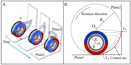
Figure 4.
Operating principle of the front wheel module. (A) Passive rotation of the tentacle and ring magnet. (B) Illustration of design details.
The design of the tentacle is critical, as it governs both the rotation characteristics and the adhesion variations. In this study, the arc curve of the tentacle was designed as a segment of a circle with a radius R1, which is larger than that of the rubber tire (R2). The center of the arc circle is positioned directly above the wheel, and the tail end of the arc is tangent to the rubber tire. This configuration ensures that the contact force at any point along the arc generates a counterclockwise rotation torque, thereby facilitating a monotonic, continuous, and stable rotation of the magnet.
Figure 5 illustrates the geometrics during the rotation of the arc tentacle. denotes the rotation angle of the ring magnet and the angle of the two planes of a corner. In , the length of segment ME is computed as:
As the rotation can be treated as an inverted T-shaped figure () which rotates around , . Hence, , and:
The length of segment EF can be expressed as:
In , applying the sine theorem yields:
Substituting Equations (1)–(4) into leads to:
Equation (5) represents the implicit geometric relationship between the rotation angle of the ring magnet and the distance to the intersection line. Given the distance to the intersection line, we can solve Equation (5) to obtain the rotation angle of the ring magnet using tools such as MATLAB’s fsolve function. Notably, the arc tentacle machanism is effective in scenarios of concave corners, and thus the angle in Equation (5) must be less than 180°. However, the arc tentacle mechanism does not produce any adverse effects at convex corners. Furthermore, due to the magnetic attraction from the ferromagnetic structures, the arc tentacle mechanism remains stable and does not sway randomly when the wheel module moves in a non-horizontal orientation.
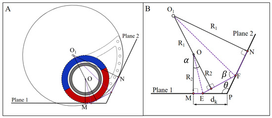
Figure 5.
Geometric relationship between the rotation angle of the ring magnet and the distance to the intersection line. (A) Contact situation. (B) Geometric schematic.
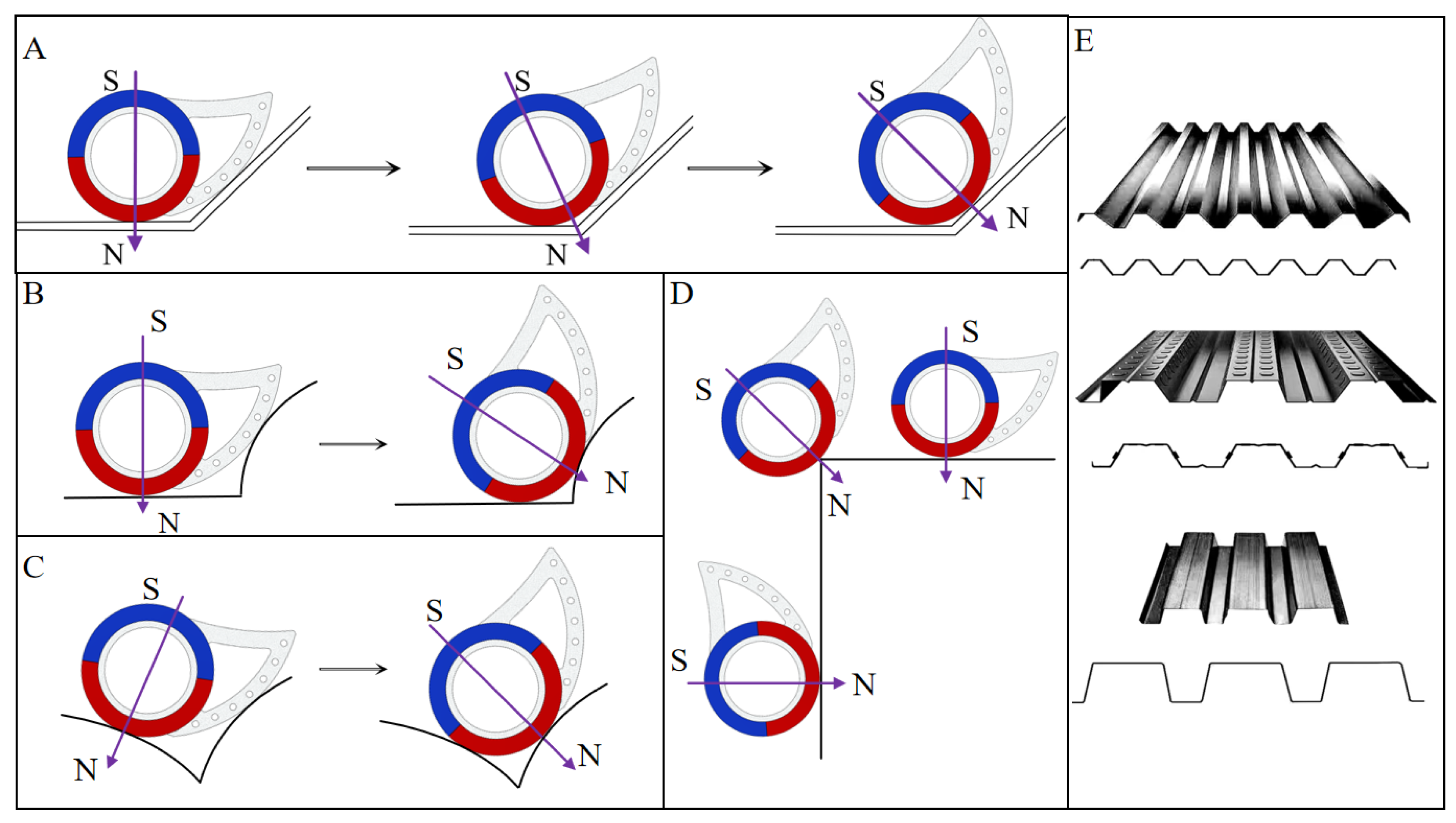
It is noteworthy that the transition process operates without active control or prior knowledge of the corner structure. Furthermore, the front wheel module is applicable to a wide range of geometries, including flat or curved surfaces, concave or convex corners with angles ranging from 90° to 315°, and complex structures such as corrugated sheets composed of multiple flat plates and alternating concave and convex corners, as depicted in Figure 6.

Figure 6.
Scenarios applicable to the front wheel module. (A) Concave corners larger than 90°. (B–D) Corners formed by flat and curved surfaces. (E) Corrugated sheets.
2.3. Magnetic Adhesion-Adaptive Rear Wheel
Due to spatial constraints, the rear wheel cannot adopt the same design as the front wheel for magnetic adhesion adjustment. To address this, an eccentric shaft-hole design is proposed for the rear wheel, ensuring secure and reliable magnetic adhesion on flat surfaces while enabling easy detachment from Plane 1 during transitions. As shown in Figure 7, the rear wheel module consists of three main components: a motor, a ring magnet, and a hub with a rubber tire. The ring magnet is axially magnetized, providing consistent adhesion during rolling motion. Table 3 summaries the technical parameters of the rear wheel module designed in this study.

Figure 7.
Structure of the magnetic adhesion-adaptive front wheel. (A) Assembly view. (B) Expanded view.
Table 3.
Technical parameters of the rear wheel module.
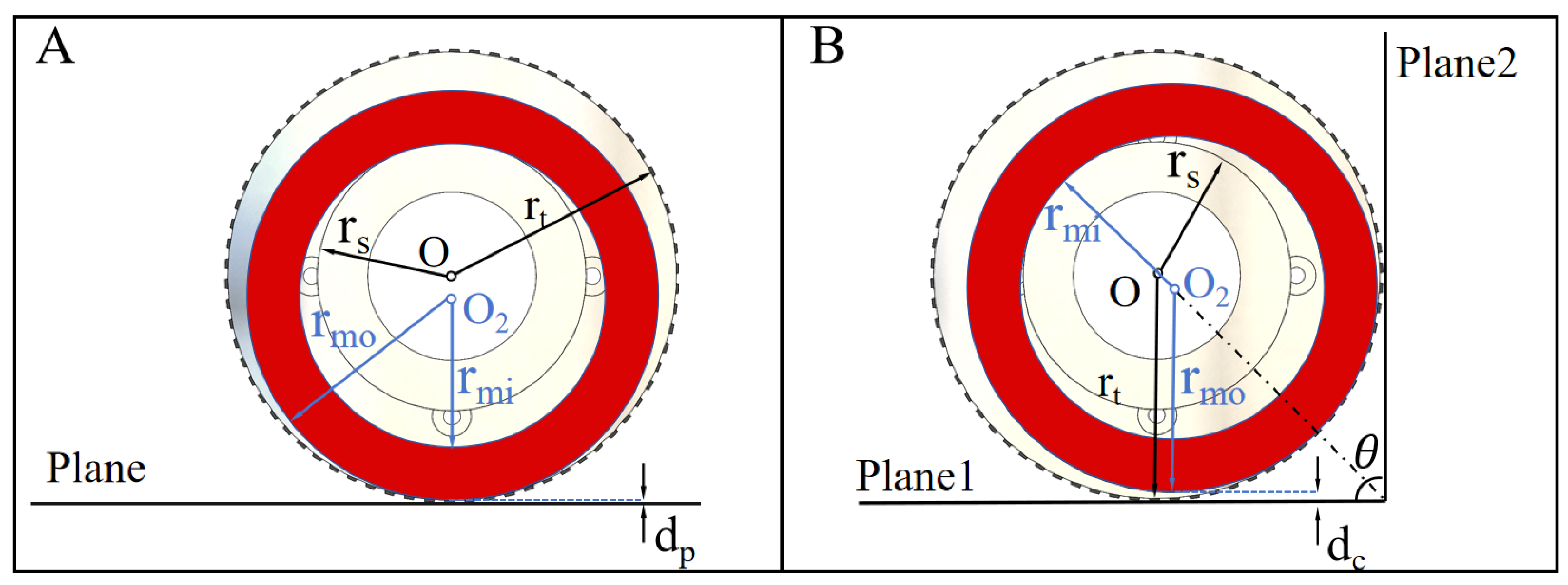
Figure 8 illustrates the operational principle of the rear wheel module with the eccentric shaft-hole design on both a flat plate and a right-angle corner. The inner diameter of the ring magnet is slightly larger than the diameter of the shaft, creating a clearance between the ring magnet and the shaft. This allows the ring magnet to rotate freely around the shaft and become misaligned with it. When the wheel module moves on a flat plate, as depicted in Figure 8A, the ring magnet is offset toward the ferrimagnetic plate due to the magnetic force, maintaining the closest possible proximity to the plate. The clearance between the ring magnet and the plate, denoted as , can be calculated as:
where and represent the radii of the rubber tire and the shaft, respectively, while and represent the inner and outer radii of the ring magnet.
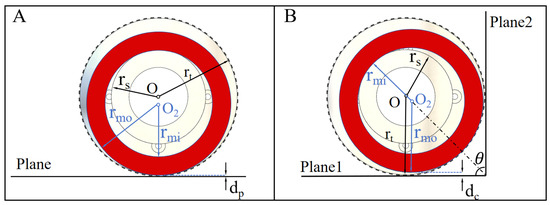
Figure 8.
Operational principle of the real wheel module. (A) On a flat surface. (B) At a concave corner.
When the wheel module traverses a concave corner, as shown in Figure 8B, the ring magnet is attracted by both plates. Assuming that the two plates are identical, the magnetic forces on Plane 1 and Plane 2 are equal, resulting in an attraction force directed along the bisector of the corner. This reorients the ring magnet, causing the contact point to shift from the top of the shaft to the distal intersection of the bisector and the outer circumference of the shaft. At this point, the clearance between the ring magnet and Plane 1, denoted as , can be expressed as:
where represents the angle of the corner. Consequently, the change in clearance () can be computed as:
Since is always greater than zero in concave corners (where ), the clearance between the ring magnet and Plane 1 increases when the wheel module approaches the corner. As a result, the magnetic force on Plane 1 decreases, facilitating the detachment of the wheel module from Plane 1 and its transition to Plane 2. From Equation (8), it is evident that a smaller corner angle results in a larger clearance change, making the transition easier. This behavior contrasts with that of standard magnetic wheels, which require greater driving force to traverse smaller concave corners.
3. Simulations
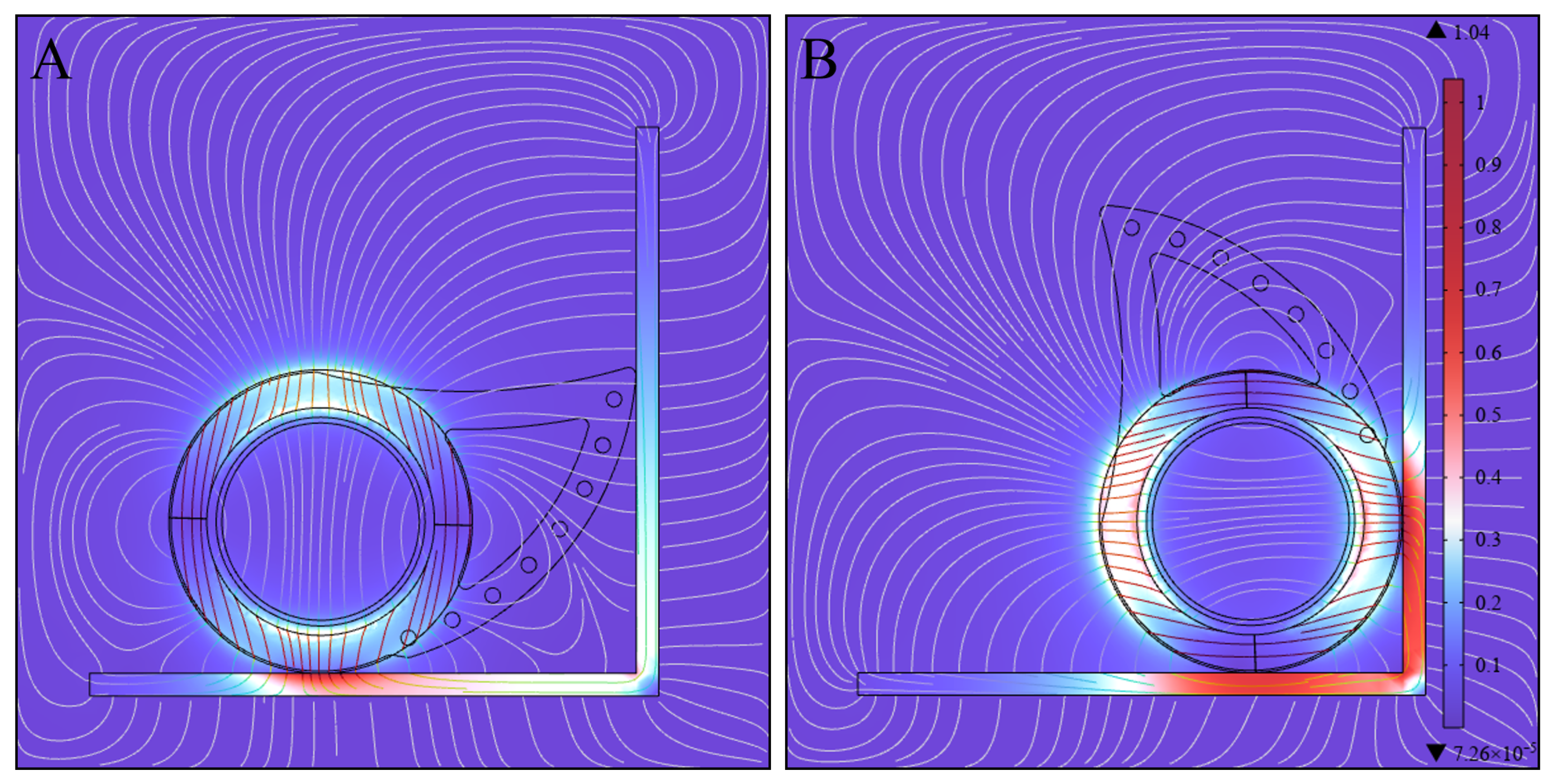
To validate the magnetic adhesion-adaptive capability of the front and the rear wheel modules, the magnetic forces during their transition across a right-angle corner were simulated using the finite element analysis (FEA) software Maxwell 2022 R2. For the front wheel module, the rotation angle of the tentacle was first calculated using Equation (5), followed by FEA simulations conducted in increments of 5°. Figure 9, Figure 10 and Figure 11 present the simulation results.
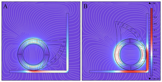
Figure 9.
Finite element analysis of the magnetic field intensityof the front wheel module during its transition across a right-angle corner. (A) The initial state, where the tentacle first makes contact with Plane 2 and the passive rotation starts. (B) The intermediate state, where the passive rotation finishes and the rubber tire achieves full contact with Plane 2.
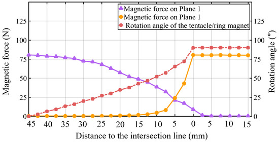
Figure 10.
Simulation results of the rotation angle and the magnetic force of the front wheel module during transition.
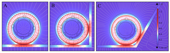
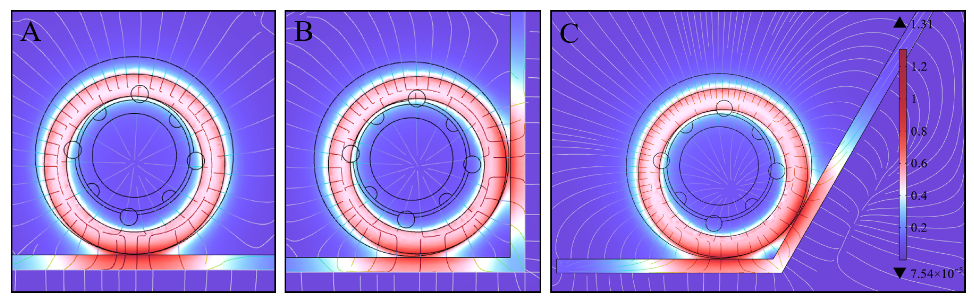
Figure 11.
Finite element analysis of the magnetic field intensityof the rear wheel module in different states. (A) The wheel module moves on a flat plate. (B) The intermediate state of the wheel module transiting across a right-angle corner. (C) The intermediate state of the wheel module transiting across a concave corner of 120°.
Figure 9 depicts the magnetic field intensity corresponding to the initial and intermediate states of the front wheel module. Figure 10 further illustrates the variation in rotation angle and magnetic forces as a function of the distance to the intersection line. In the initial state where the tentacle first contacts Plane 2, the magnetic forces of the front wheel module on Plane 1 and Plane 2 are 80.5 N and 0.3 N, respectively. At this point, the tentacle begins to rotate under the pressure exerted by Plane 2. As the distance between the front wheel module and Plane 2 decreases, the tentacle gradually rotates, causing the magnetic force on Plane 1 to continuously decrease, while the magnetic force on Plane 2 increases slowly at first and more rapidly in the middle and later stages. Notably, when the distance reaches approximately 13 mm, the two magnetic forces become roughly equal. When the distance decreases to 0, the tentacle rotates approximately 90°, and the magnetic forces on Plane 1 and Plane 2 are 9.1 N and 80.8 N, respectively. Compared to the magnetic force profiles shown in Figure 2, the arc tentacle mechanism enables the early reduction in magnetic force on Plane 1 while simultaneously promoting the premature increase in magnetic force on Plane 2. Consequently, the arc tentacle mechanism significantly enhances the front wheel’s ability to smoothly transition between planes, eliminating the need for complex control systems.
Figure 11 illustrates the magnetic field intensity corresponding to different states of the rear wheel module in various scenarios. As shown in Figure 11A, when the wheel module moves on a flat plate, the ring magnet remains closest to the plate and misaligns with the shaft, generating a magnetic force of 110.3 N. In Figure 11B,C, during the intermediate state of transiting across concave corners of 90° and 120°, the center of the ring magnet shifts to the bisector of the corner, increasing the clearance between the ring magnet and Plane 1. Consequently, the magnetic forces on Plane 1 decrease to 60.1 N and 69.2 N for the 90° and 120° corners, respectively, corresponding to 0.54 and 0.63 of the magnetic force on the flat plate. This further validates that the smaller the corner angle, the greater the reduction in magnetic force.
4. Experiments
To validate the effectiveness of the proposed robot design, a prototype of the BiMagBot was developed, and three sets of experiments were conducted. During the tests, the robot was remotely controlled by a human operator using a joystick. It is important to emphasize that no motion control was applied during the transition process. A demonstration video of the tests is available at https://youtu.be/ZFzFC2zNvb8 (accessed on 10 February 2025).
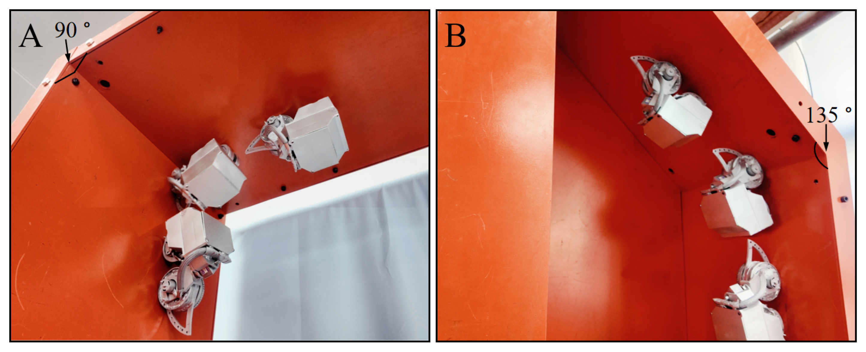
Figure 12 depicts the movement of the robot in the first set of experiments, where the robot transitioned across 90° and 135° concave corners, moving from the ceiling to a vertical surface and from a vertical surface to the ceiling, respectively. Due to the absence of the need for sensing or control, the robot completed each transition in less than 1 s.

Figure 12.
Demonstration of BiMaBot transiting across concave corners. (A) 90°. (B) 135°.
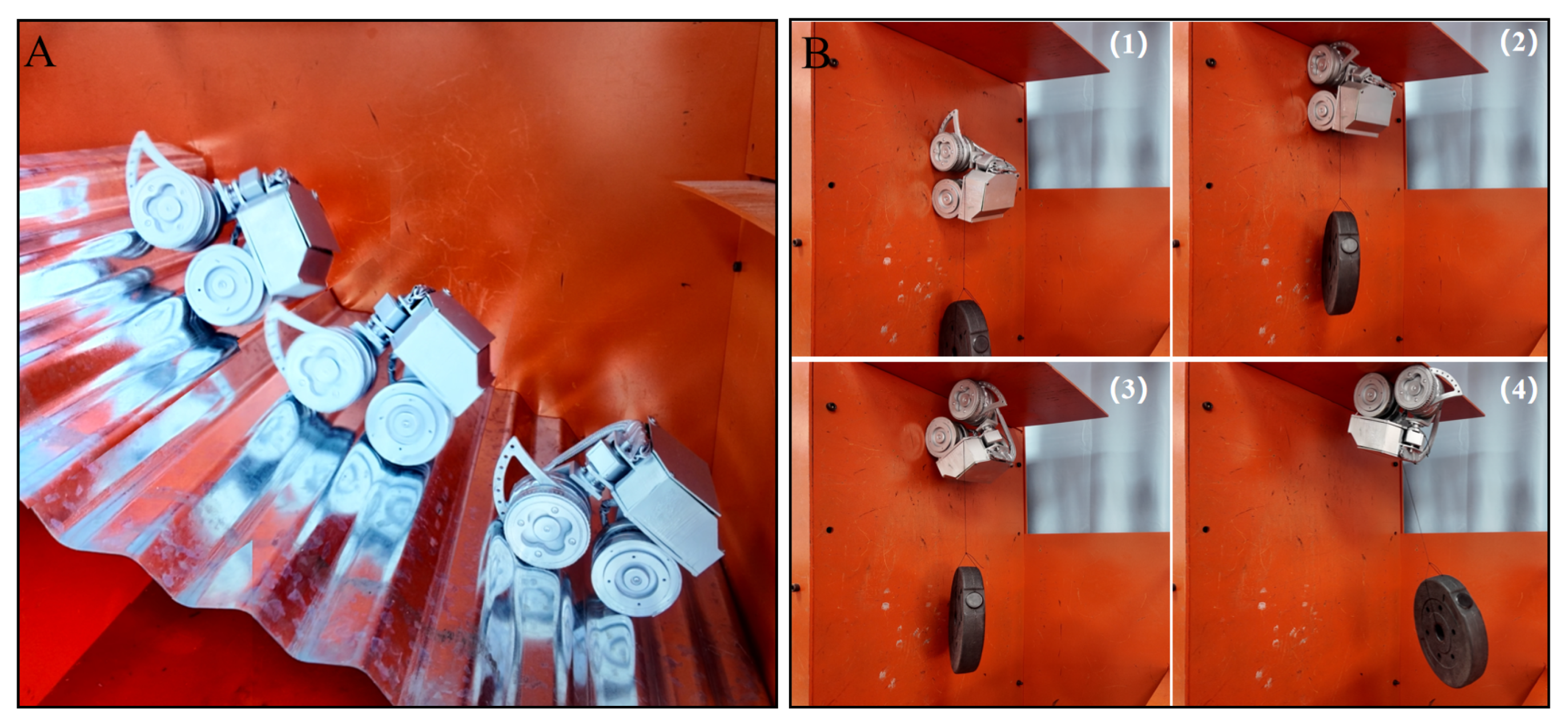
The second set of experiments was conducted to further evaluate the robot’s transition performance. Figure 13A shows the robot’s movement as it climbed on a corrugated plate, a task that remains challenging for traditional wheeled climbing robots. The video demonstrates that the BiMagBot successfully navigated the corrugated plate in a short time, showcasing its exceptional ability to traverse densely structured corners. Figure 13B presents snapshots, highlighting the BiMagBot’s successful transition across a right-angle corner from a vertical surface to the ceiling while carrying a 2 kg payload, which exceeds its own weight.
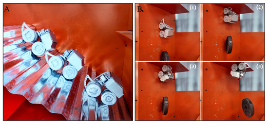
Figure 13.
Experiments to access the BiMagBot’s transition performance. (A) Navigating the corrugated plate. (B) Performing transition while carrying payload, wherein numbers indicate the sequence.
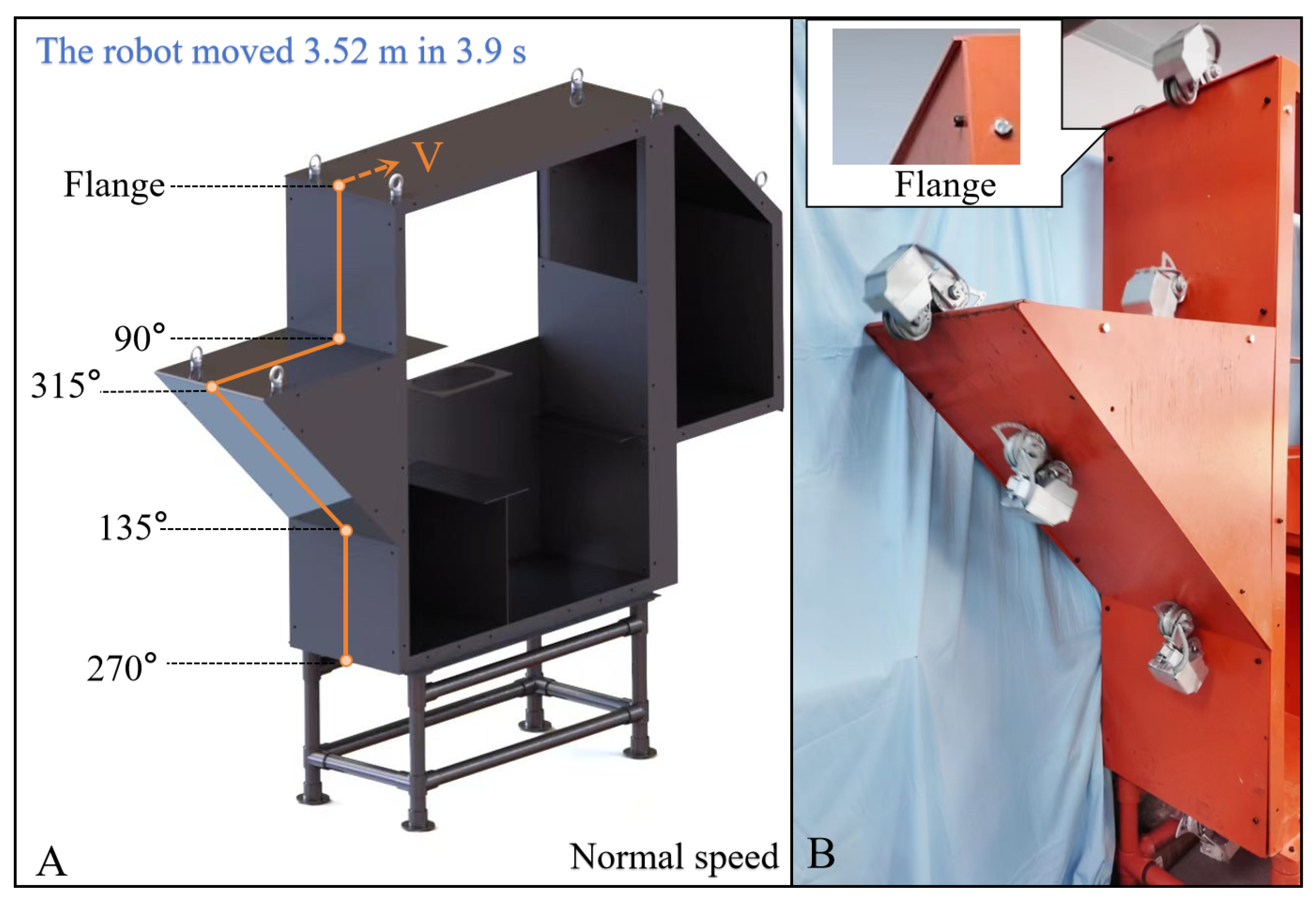
The third set of experiments was conducted to further evaluate the robot’s speed. Figure 14A shows the route for testing, including four concave and convex corners of different angles, as well as a flange, with a total length of 3.52 m. Figure 14B shows the movement of the robot as it climbed along the preset route at the fastest speed. The video shows the BiMagBot successfully completing the climb along the path in 3.9; hence, its speed was 0.9 m/s, demonstrating the BiMagBot’s fast moving speed and plane-transition efficiency.

Figure 14.
Experiments to access the BiMagBot’s speed of motion. (A) Path. (B) Prototype demonstration.
5. Conclusions
Magnetic-wheeled climbing robots offer significant advantages for the inspection of ferromagnetic structures, yet their capabilities for transitioning between planes require further enhancement.
In this study, we developed a novel climbing robot. The robot adopts the configuration of single steering and two-wheel drive. Magnetic adhesion is provided by two magnetic wheels, with both front and rear wheels incorporating magnetic adhesion-adaptive mechanisms. These mechanisms allow the robot to adjust magnetic adhesion without the need for active control. The experimental results showed that the front and rear wheels can adjust the magnetic adhesion during the transition of concave or convex corners with angles ranging from 90° to 315°. The robot weighs only 1.6 kg, but it can carry a payload of 2 kg with a climbing speed of 0.9 m/s to transit concave corners, demonstrating comprehensive capabilities in plane transition, ease of control, and load capacity.
In the future, we intend to study the optimization design of the arc curve of the tentacle to further improve the plane-transition performance. Moreover, we plan to improve the operational capabilities of the robot by equipping it with specialized tools to perform specific tasks.
Author Contributions
Y.B. and H.Z. conceptualized the research. Y.B. and L.D. developed the robot, conducted the simulations and experiments, and wrote the manuscript. Y.D. processed the data. A.J. supported the experiments. B.J. and H.Z. supervised the study. All authors have read and approved the manuscript.
Funding
This research was funded in part by the Basic and Applied Basic Research Fund of Guangdong Province under Grant Number 2024A1515011871 and Grant Number 2022A1515240013, and in part by the Science and Technology Project of Guangdong Provincial Administration for Market Regulation under Grant Number XMBH20230413025.
Data Availability Statement
The data presented in this study are available on request from the corresponding authors.
Conflicts of Interest
The authors declare no conflicts of interest.
References
- Eich, M.; Bonnin-Pascual, F.; Garcia-Fidalgo, E.; Ortiz, A.; Bruzzone, G.; Koveos, Y.; Kirchner, F. A robot application for marine vessel inspection. J. Field Robot. 2014, 31, 319–341. [Google Scholar] [CrossRef]
- Zhang, X.; Zhang, M.; Jiao, S.; Zhang, X.; Li, M. Optimization Design and Parameter Analysis of a Wheel with Array Magnets. Symmetry 2023, 15, 962. [Google Scholar] [CrossRef]
- Wang, R.; Kawamura, Y. An automated sensing system for steel bridge inspection using GMR sensor array and magnetic wheels of climbing robot. J. Sens. 2016, 2016, 8121678. [Google Scholar] [CrossRef]
- Tavakoli, M.; Viegas, C.; Marques, L.; Pires, J.N.; de Almeida, A.T. Magnetic omnidirectional wheels for climbing robots. In Proceedings of the 2013 IEEE/RSJ International Conference on Intelligent Robots and Systems, Tokyo, Japan, 3–7 November 2013; IEEE: Piscataway, NJ, USA, 2013; pp. 266–271. [Google Scholar]
- Song, Y.K.; Lee, C.M.; Koo, I.M.; Tran, D.T.; Moon, H.; Choi, H.R. Development of wall climbing robotic system for inspection purpose. In Proceedings of the 2008 IEEE/RSJ International Conference on Intelligent Robots and Systems, Nice, France, 22–26 September 2008; IEEE: Piscataway, NJ, USA, 2008; pp. 1990–1995. [Google Scholar]
- Han, S.C.; Kim, J.; Yi, H.C. A novel design of permanent magnet wheel with induction pin for mobile robot. Int. J. Precis. Eng. Manuf. 2009, 10, 143–146. [Google Scholar] [CrossRef]
- Zhang, L.; Sun, J.; Yin, G.; Zhao, J.; Han, Q. A cross structured light sensor and stripe segmentation method for visual tracking of a wall climbing robot. Sensors 2015, 15, 13725–13751. [Google Scholar] [CrossRef] [PubMed]
- Nguyen, S.T.; Nguyen, H.; Bui, S.T.; Ho, V.A.; La, H.M. Multi-directional bicycle robot for steel structure inspection. arXiv 2021, arXiv:2103.11522. [Google Scholar]
- Sirken, A.; Knizhnik, G.; McWilliams, J.; Bergbreiter, S. Bridge risk investigation diagnostic grouped exploratory (BRIDGE) bot. In Proceedings of the 2017 IEEE/RSJ International Conference on Intelligent Robots and Systems (IROS), Vancouver, BC, Canada, 24–28 September 2017; IEEE: Piscataway, NJ, USA, 2017; pp. 6526–6532. [Google Scholar]
- Tâche, F.; Fischer, W.; Caprari, G.; Siegwart, R.; Moser, R.; Mondada, F. Magnebike: A magnetic wheeled robot with high mobility for inspecting complex-shaped structures. J. Field Robot. 2009, 26, 453–476. [Google Scholar] [CrossRef]
- Eto, H.; Asada, H.H. Development of a wheeled wall-climbing robot with a shape-adaptive magnetic adhesion mechanism. In Proceedings of the 2020 IEEE International Conference on Robotics and Automation (ICRA), Paris, France, 31 May–31 August 2020; IEEE: Piscataway, NJ, USA, 2020; pp. 9329–9335. [Google Scholar]
- Romao, J.C.; Tavakoli, M.; Viegas, C.; Neto, P.; de Almeida, A.T. InchwormClimber: A light-weight biped climbing robot with a switchable magnet adhesion unit. In Proceedings of the 2015 IEEE/RSJ International Conference on Intelligent Robots and Systems (IROS), Hamburg, Germany, 28 September–3 October 2015; IEEE: Piscataway, NJ, USA, 2015; pp. 3320–3325. [Google Scholar]
- Hong, S.; Um, Y.; Park, J.; Park, H.W. Agile and versatile climbing on ferromagnetic surfaces with a quadrupedal robot. Sci. Robot. 2022, 7, eadd1017. [Google Scholar] [CrossRef] [PubMed]
- Lee, W.; Hirai, M.; Hirose, S. Gunryu III: Reconfigurable magnetic wall-climbing robot for decommissioning of nuclear reactor. Adv. Robot. 2013, 27, 1099–1111. [Google Scholar] [CrossRef]
- Lin, T.H.; Putranto, A.; Chen, P.H.; Teng, Y.Z.; Chen, L. High-mobility inchworm climbing robot for steel bridge inspection. Autom. Constr. 2023, 152, 104905. [Google Scholar] [CrossRef]
- Tavakoli, M.; Lourenco, J.; Viegas, C.; Neto, P.; de Almeida, A.T. The hybrid OmniClimber robot: Wheel based climbing, arm based plane transition, and switchable magnet adhesion. Mechatronics 2016, 36, 136–146. [Google Scholar] [CrossRef]
- Ueno, S.; Nakajima, M.; Tanaka, M. Development of an articulated mobile robot moving on magnetic curved walls and passing over obstacles. Adv. Robot. 2022, 36, 1156–1171. [Google Scholar] [CrossRef]


Disclaimer/Publisher’s Note: The statements, opinions and data contained in all publications are solely those of the individual author(s) and contributor(s) and not of MDPI and/or the editor(s). MDPI and/or the editor(s) disclaim responsibility for any injury to people or property resulting from any ideas, methods, instructions or products referred to in the content. |
© 2025 by the authors. Licensee MDPI, Basel, Switzerland. This article is an open access article distributed under the terms and conditions of the Creative Commons Attribution (CC BY) license (https://creativecommons.org/licenses/by/4.0/).