Abstract
Vision-based UAV-AGV (Unmanned Aerial Vehicle–Autonomous Ground Vehicle) systems are prominent for executing tasks in GPS (Global Positioning System)-inaccessible areas. One of the roles of the UAV is guiding the navigation of the AGV. Reactive/mapless navigation assistance to an AGV from a UAV is well known and suitable for computationally less powerful systems. This method requires communication between both agents during navigation as per state of the art. However, communication delays and failures will cause failures in tasks, especially during outdoor missions. In the present work, we propose a mapless technique for the navigation of AGVs assisted by UAVs without communication of obstacles to AGVs. The considered scenario is that the AGV is undergoing sensor and communication module failure and is completely dependent on the UAV for its safe navigation. The goal of the UAV is to take AGV to the destination while guiding it to avoid obstacles. We exploit the autonomous tracking task between the UAV and AGV for obstacle avoidance. In particular, AGV tracking the motion of the UAV is exploited for the navigation of the AGV. YOLO (You Only Look Once) v8 has been implemented to detect the drone by AGV camera. The sliding mode control method is implemented for the tracking motion of the AGV and obstacle avoidance control. The job of the UAV is to localize obstacles in the image plane and guide the AGV without communicating with it. Experimental results are presented to validate the proposed method. This proves to be a significant technique for the safe navigation of the AGV when it is non-communicating and experiencing sudden sensor failure.
1. Introduction
A heterogeneous UAV-AGV system is one of the popular two-agent systems focused on by many researchers. The system can be either communicative or non-communicative depending on whether data communication is present between the UAV and AGV. The UAV overcomes the limitations of the AGV, and the AGV is stronger at the limitations of the UAV [1]. Thus, the individual capabilities of each agent can complement each other. Industrial inspection, target tracking, agriculture, and environment mapping are potential applications of the system. The vision-based UAV-AGV (camera attached to the UAV or AGV or both) combination came into existence to deal with missions involving poor GPS (Global Positioning System) accessibility [2,3]. In a vision-based UAV-AGV system, vision sensors (cameras) are used for the relative localization of the agents. For example, the UAV can have a down-facing camera to localize the AGV relative to it [4]. Visual markers are placed on the AGV for unique identification by the UAV vision sensor. Or the AGV can be equipped with a sky-facing camera to localize the UAV. Either of the agents can be the leader, with the other being the follower, according to the mission requirements [2,3]. Take-off, tracking, and landing are basic functionalities of the system for executing collaborative tasks. Vision-based solutions for the execution of basic functionalities are reported in the literature by various authors [4,5,6,7,8,9,10,11]. However, most of the literature work focused on the AGV being the leader and the UAV as the follower. In this work, we consider the counter situation where the UAV is the leader and the AGV is the follower. This scenario is useful when the AGV has to support longer missions of the UAV by tracking it. In this work, we show that the UAV leader and AGV follower system is also useful for the navigation of the AGV.
The UAV-AGV system is suitable for tasks/missions requiring air–ground automation. A recent review identifies different roles of the UAV and AGV for a task and presents a detailed review from the application perspective [3]. The kinematics framework specific to the vision-based UAV-AGV system reported in [5] presents forward and inverse kinematics notions for the system. Few researchers have implemented the system in applications such as inspection [12], indoor data collection [13], construction site preparation [14], and mapping [15,16]. Thus, research on the vision-based UAV-AGV system is advancing in the direction of improving and increasing the system capabilities as well as implementation in industrial applications. One of the advantages of joining the UAV with the AGV is that it can act like an eye in the sky and provide navigation guidance to the AGV [17]. The UAV, with its large FOV (Field of View) via a down-facing camera, can efficiently guide the AGV to its destination [3,4]. On the other hand, deep neural network (DNN)-based approaches are dominating in autonomous systems for localization, control, and planning [18]. In particular, a CNN (Convolutional Neural Network)-based deep learning technique has been applied for robust vision-based detection of the AGV by the UAV [5].
The UAV/AGV system can undergo sudden sensor faults during the execution of missions, especially under outdoor conditions. For instance, during safety and rescue missions, there are high chances of possible faults [1]. This work considers navigation problems in the event of an AGV that is facing a sudden failure of its sensor and communication modules. In this context, the AGV cannot send/receive data, and also, the navigation sensors, such as the GPS, have failed. Under these conditions, the AGV completely depends on the aerial agent for its safe navigation. In this work, we propose a non-communicative and sensorless navigation technique for the AGV and also experimentally validate the technique. Both the UAV and AGV are equipped with an onboard vision sensor. The UAV, with its down-facing camera, can localize obstacles and virtually avoid them in its plane of motion. The AGV, with its sky-facing camera, can localize and track the motion of the UAV. So, by tracking the UAV, the AGV can avoid physical obstacles.
2. Related Work and Present Contribution
The state of the art is discussed in three subsections to highlight the problems addressed in the present work.
2.1. Reactive Navigation of AGV Assisted by UAV
A UAV can guide the navigation of an AGV through map-based and mapless techniques [19]. Map-based techniques can be offline or online. In the offline technique, the UAV, AGV, or both initially scan the entire zone and create a navigation map for the AGV. In [16], the UAV first sweeps through the area and sends the map to the AGV after reaching the destination. Then, the AGV navigates to the destination using the obstacle map provided by the UAV. In [13], the AGV is manually controlled to create the map of the indoor environment. Then, the AGV carries the UAV and performs the indoor surveillance task. Whenever the AGV is unable to reach any location, it sends the UAV to collect the data. Mapless navigation of ground vehicles is also important for avoiding obstacles during the mission. This technique depends upon the current sensor data [20]. In the case of sensor damage in the AGV, the UAV can provide navigation guidance to the AGV [21]. Mapless navigation techniques for an AGV by a UAV are also reported in the literature. The UAV continuously tracks the AGV, and if any obstacles are detected in its FOV, the UAV communicates the position of the obstacle to the AGV with respect to the body frame of the AGV and a world frame [21]. In [22], an obstacle avoidance method for an AGV assisted by a UAV is reported to be similar to the previous work. However, the UAV does not track the AGV and is used to localize only obstacles during its navigation to the destination. And then, the UAV communicates the obstacle position to the AGV. In [19], a similar work is reported; however, the UAV communicates the obstacle map to the AGV after reaching the destination. In a recent study [23], a path-following strategy for an AGV assisted by a UAV is reported. The UAV continuously detects and communicates the path points to AGV. These studies indicate the importance of real-time navigation guidance provided to an AGV by a UAV. Mapless methods require the system to be communicative (data communication between both vehicles) as per state-of-the-art literature. Thus, existing mapless techniques are not suitable if the AGV is non-communicating or unable to communicate. Communication failures between both agents can occur during outdoor missions. The problem becomes more challenging if the AGV is also experiencing sensor damage. In the present work, we propose a simple yet novel mapless obstacle avoidance technique for an AGV assisted by a UAV. The present technique is suitable even if the system is non-communicating and may only be for simple environments. Tracking motion between both vehicles is exploited to develop an obstacle avoidance technique for the AGV.
2.2. Ground Vehicle Tracking Aerial Vehicle
Tracking is a well-known basic collaborative motion between a UAV and an AGV. This collaborative motion is necessary for executing any kind of mission by the UAV-AGV system. Tracking tasks can either be the UAV following the AGV or vice versa. The former (the AGV tracking the motion of the UAV) is well established in the literature. Several researchers have reported vision-based solutions for a UAV tracking an AGV where unique identification markers are placed over the AGV for localization purposes [5,6,7,8]. Another way of tracking motion between them is the AGV tracking the motion of the UAV. Both agents can have different functional roles according to the collaborative task. The AGV can assist the parcel delivery missions of the UAV by acting as a mobile carrier [3,24]. This situation may require the AGV to follow the UAV to assist it. When the UAV is non-cooperative during a mission and if the role of the AGV is to support (payload and tethered charging support) the longer mission of the UAV, the AGV must continuously track the motion of the UAV to assist it. Interestingly, the tracking task of the AGV can also be useful for its safe navigation, which is proposed in this work. Thus, the AGV tracking the motion of the UAV is as equally important as the UAV following the AGV. However, it is less focused on as per the literature studies [25,26,27,28]. Few authors have worked on this problem. In [25], an expert PID (Proportional Integral Derivative) controller is developed for a non-holonomic AGV to track the UAV. However, localization is based on a motion capture system and is not suitable for outdoor missions, and communication is required between both agents. Multiple AGVs reaching the projection of the center of the UAV (static/hovering) on the ground plane are presented in [26]. This study is not vision-based; the UAV is not dynamic and is limited to simulations. Studies [27,28] dealt with waypoint navigation of an AGV in the image frame of a hovering UAV. Our research group has reported a communicative tracking strategy for an AGV to track a UAV in GPS-less conditions [29]. Though it works in outdoor and GPS-less conditions, the method strongly depends on data communication between the UAV and AGV. Thus, the problem of AGVs tracking UAVs (without GPS and communication) is not addressed as per the literature survey, considering the vision-based UAV-AGV system. We propose a vision-based and non-communicative strategy for an AGV to track a UAV, which is suitable for outdoor missions. This is one of the contributions of this work.
2.3. Vision-Based Detection of UAVs/Drones
The localization of a drone in a ground vehicle camera is one of the challenges in outdoor conditions. Unique identification markers and LEDs (Light-Emitting Diodes) are attached to aerial vehicles for localization in AGV cameras in the literature. In [13], a Whycon marker is attached at the bottom of a Blimp UAV. Classical machine vision techniques are applied to localize the marker in the AGV camera [13]. However, attaching markers on the bottom of quadcopters may not be feasible. It may affect the behavior of the flight of the drone as it partially blocks the airflow at the bottom. In [30], LEDs are attached to the arms of a drone for detection in an AGV camera. But this technique is highly influenced by outdoor light conditions. So, the drone must be localized through its structural features rather than using features of externally attached markers. Thus, for the robust detection of drones in the AGV camera, we have implemented a deep-learning-based technique.
In this work, we first developed a vision-based and non-communicative tracking strategy for AGV to track the motion of the UAV. This tracking motion is used to assist the navigation of the AGV to avoid obstacles. The UAV detects and localizes obstacles in its down-facing camera and avoids virtual obstacles in the plane of its motion. Virtual obstacles are projections of physical ones on the plane motion of the UAV. This enables the AGV to avoid physical obstacles. The method is detailed in Section 3. The proposed technique is validated for a non-cooperative scenario (there is no data communication between the UAV and AGV). Overall, the contributions of the present work are summarized as follows:
- A deep-learning-based method is applied to localize the UAV in the camera of the AGV.
- An autonomous vision-based and non-communicative strategy for the AGV to track the UAV using its onboard sky-facing camera is presented.
- A heading control strategy for the AGV, which ensures the direction of motion of the AGV is always towards the projection center of the UAV on the ground plane, is proposed.
- A novel obstacle avoidance method for the AGV assisted by the UAV without the requirement of communication between both agents and its experimental validation are presented.
The organization of the paper is as follows: The proposed methodology is discussed in Section 3. Localization of the AGV, UAV, and obstacle is discussed in Section 4. In Section 5, controllers designed for tracking and obstacle avoidance are presented. Hardware is described in Section 6. The experimental results are discussed in Section 7, and finally, conclusions are drawn in Section 8.
3. Methodology
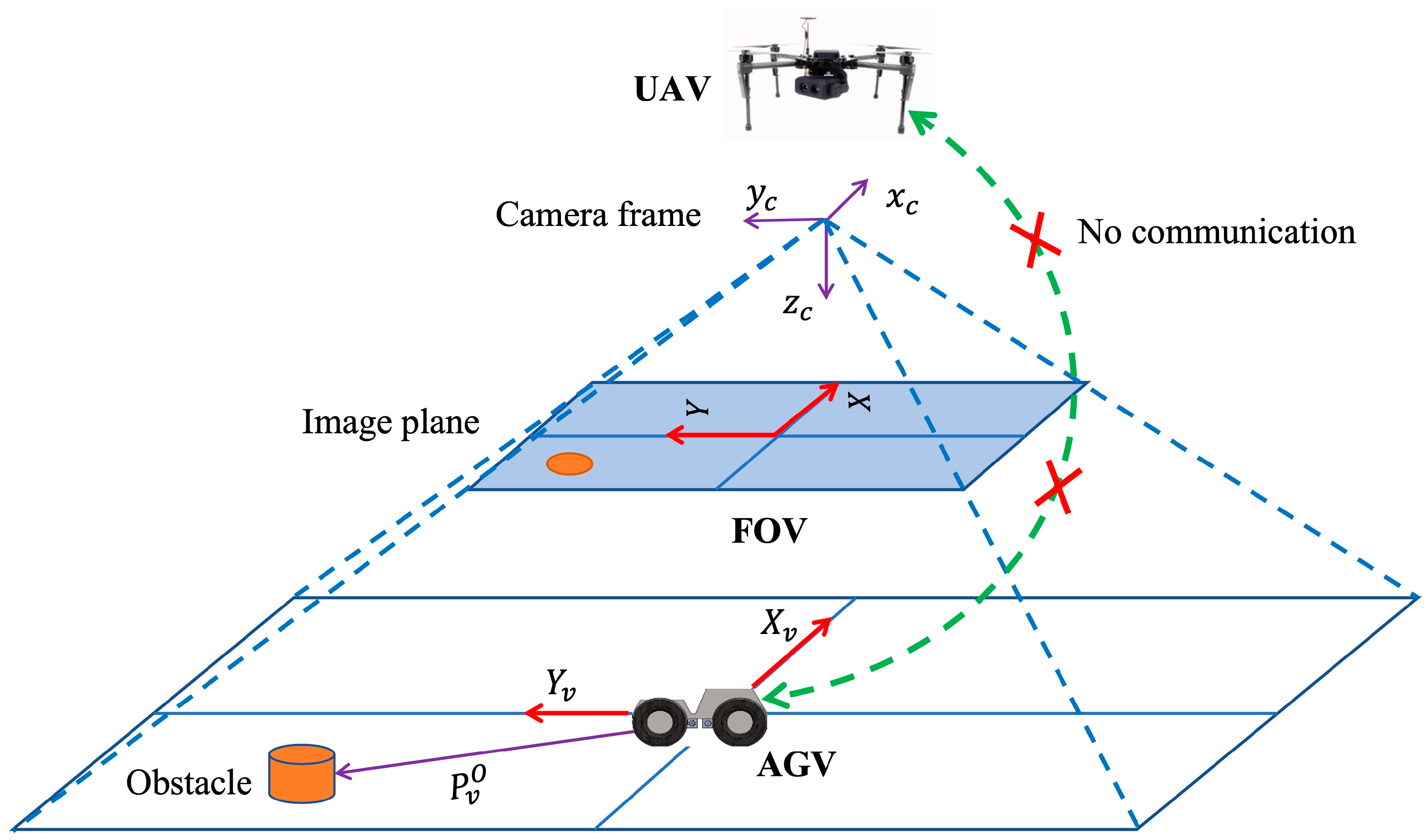
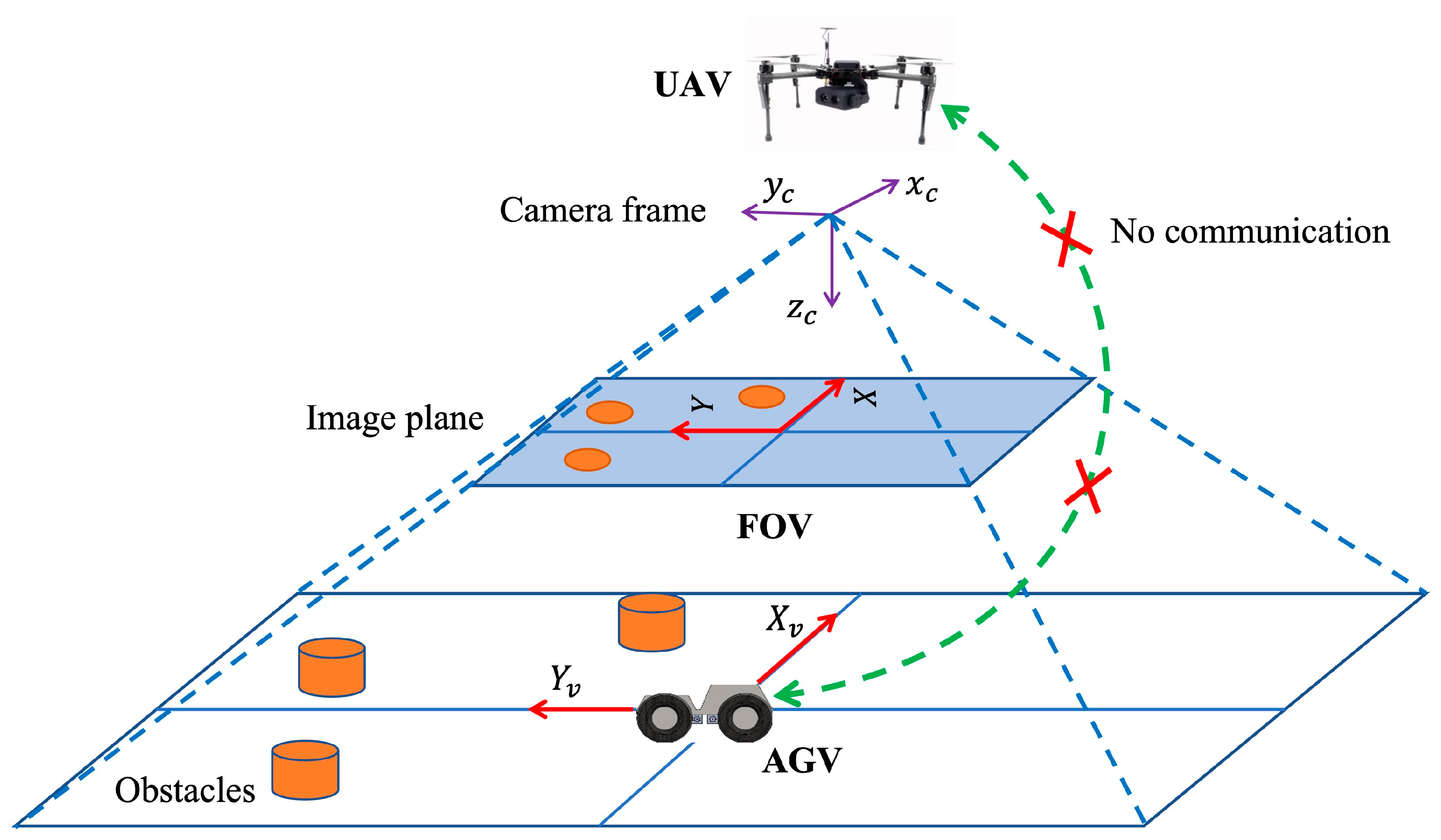
One of the roles of the UAV is to guide the navigation of the AGV in collaborative missions. The UAV can support the reactive obstacle avoidance of the AGV by communicating the location of obstacles. The literature shows navigation guidance by a UAV when an AGV is experiencing a sensor failure [21]. However, it suits the communicative scenario as discussed earlier. If the system is non-communicating, the existing methods are not applicable. We considered a more complex situation in this work. The problem we considered is that the AGV is faulty due to the failure of its sensor and communication modules. So, it cannot send/receive data and cannot execute navigation by itself. So, it completely depends upon the UAV for its safe navigation. We propose that the AGV can track the motion of the UAV for its safe navigation. The UAV can localize the obstacles on the ground and avoid virtual obstacles (projection of physical obstacles in the plane of motion) in the plane of motion. For a non-cooperating system in GPS-denied environments, visual markers must be placed on each agent for localization. The AGV can have a sky-facing camera [13,30], and the UAV can have a down-facing camera. The AGV can localize the UAV with respect to it and can track the motion of the UAV. The UAV can localize the physical obstacles on the ground plane and avoid virtual obstacles in its plane of motion. This will enable the AGV to avoid obstacles on the ground plane. However, this technique depends on the accuracy of the tracking motion of the AGV. Figure 1 illustrates the obstacle avoidance scenario considered in this work. The UAV localizes the obstacle using its down-facing camera. The AGV is unable to receive any data from any external source/UAV and is also experiencing sudden sensor failure. Thus, it completely depends on the UAV for its safe navigation. is a virtual plane fixed at the center of the AGV, and is the image plane of the UAV camera. is the apparent position of the obstacle with respect to the virtual plane of the AGV. The AGV is tracking and underneath the UAV. When an obstacle is detected in the FOV, then the UAV takes action to avoid it virtually based on the position of the obstacle with respect to the virtual plane of the AGV. Consequently, the AGV avoids the physical obstacle. The size of the obstacle is assumed to be less than or equal to the size of the AGV.
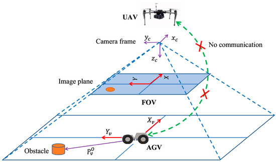
Figure 1.
Illustration of obstacle avoidance problem.
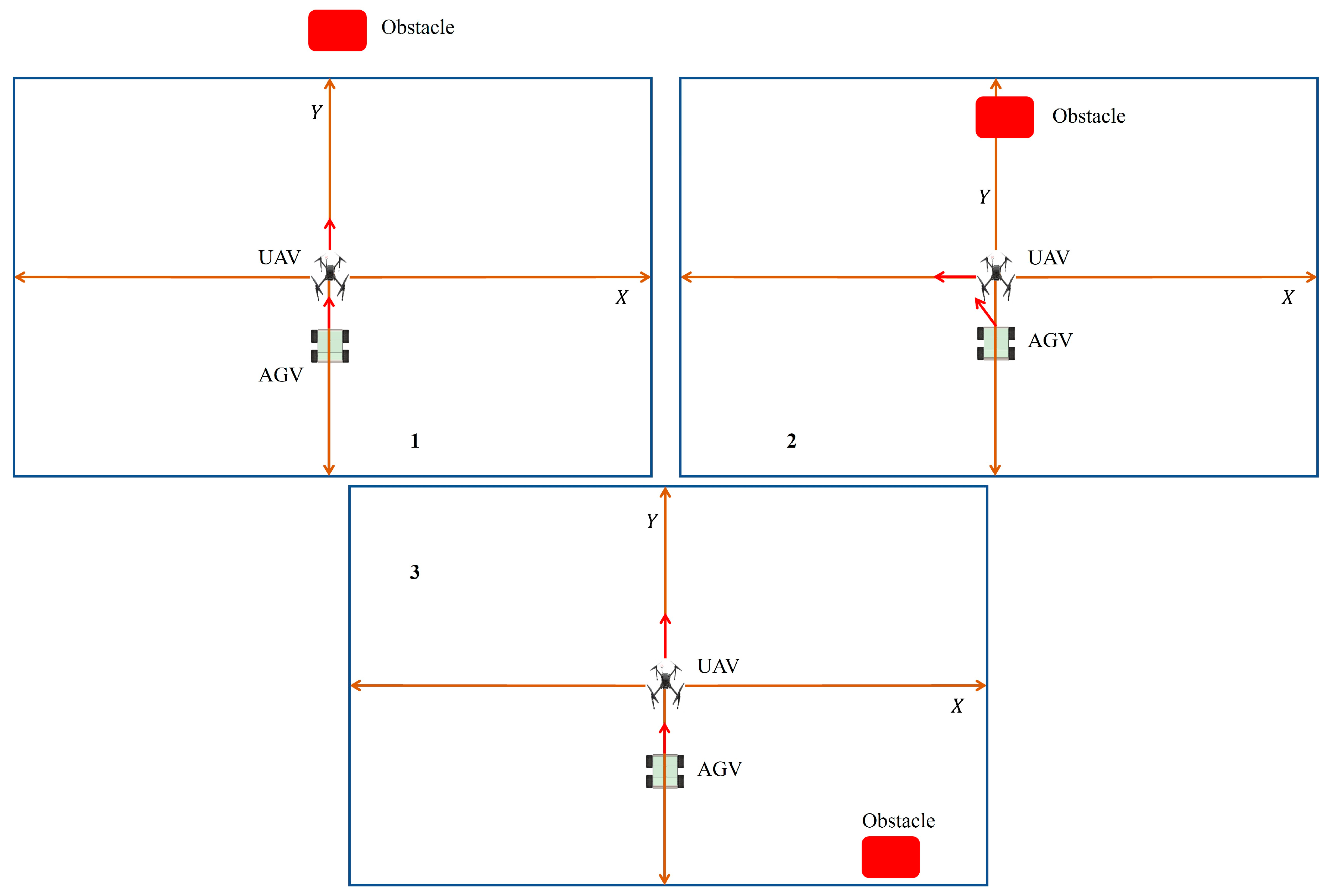
In the present work, the proposed technique is validated for a non-communicative system. The UAV does not communicate any information to the AGV for both tracking and obstacle avoidance tasks, unlike in [21,22]. Figure 2 shows the sequence of motion instants of the system for avoiding obstacles. When an obstacle does not fall in the FOV of the UAV, the AGV keeps tracking the motion of the UAV as in instant 1. When the obstacle appears in the FOV, the UAV stops moving forward and makes a decision (either to move left or right) depending on the position of the obstacle with respect to the virtual plane (VP) of the AGV. This is shown in instant 2. When the obstacle is sufficiently far from the AGV, the UAV stops moving to the left and starts moving towards the goal or in a forward direction, as shown in instant 3. As the AGV keeps tracking the UAV, it will be able to avoid the obstacle on the ground. The direction of UAV motion during obstacle avoidance depends on the position of the obstacle with respect to the virtual plane of the AGV but not with respect to the image frame of the UAV.
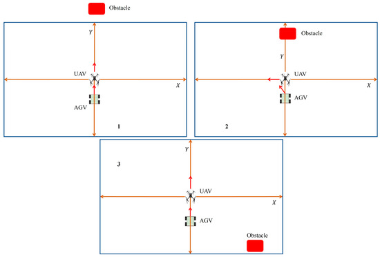
Figure 2.
Methodology of proposed technique.
4. Relative Localization of AGV, UAV, and Obstacle
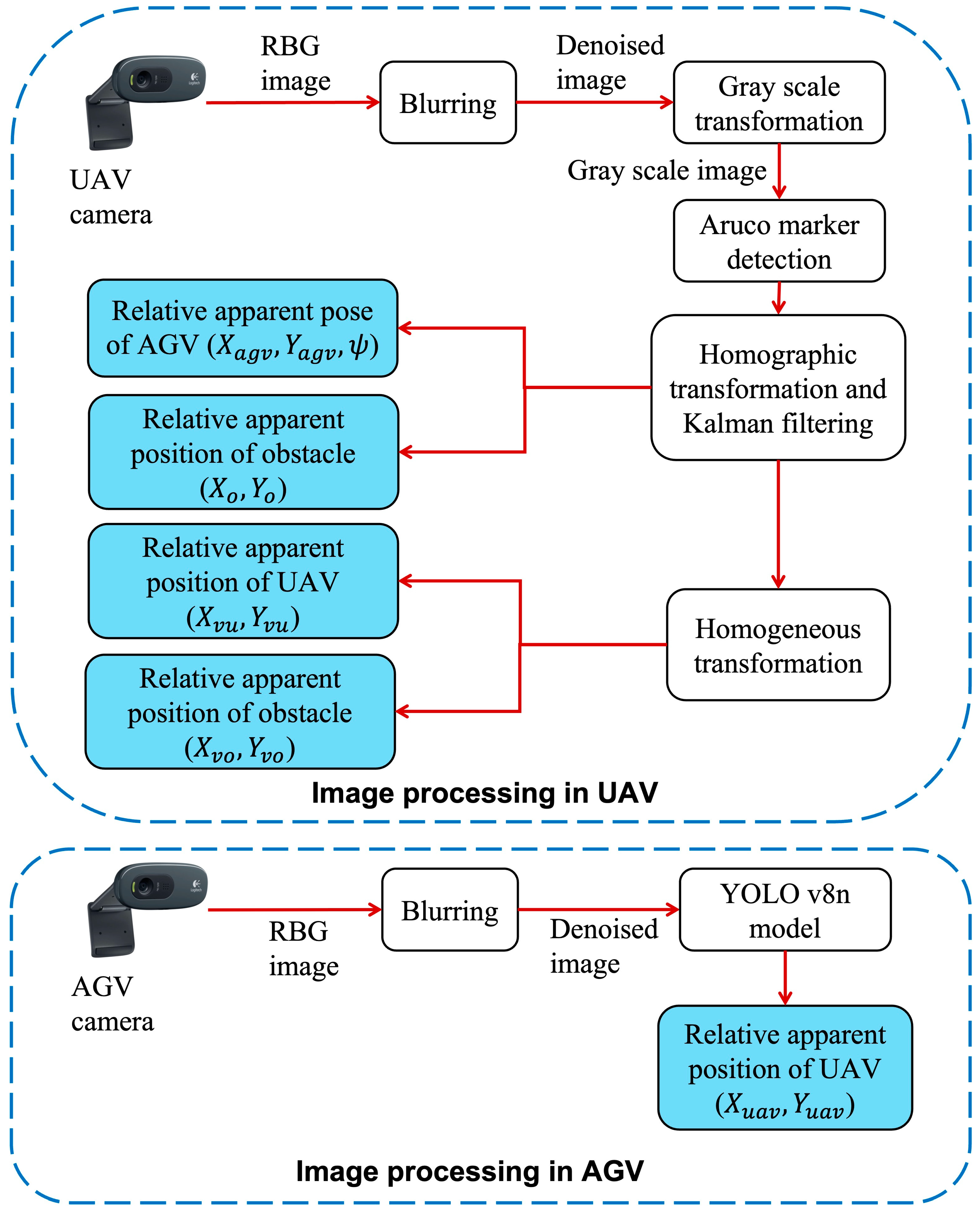
Both agents are relatively localized with each other using their onboard cameras. The sequence of image processing operations in both the UAV and AGV is shown in Figure 3. Initially, RBG (Red–Blue–Green) images from the camera are blurred for denoising. The denoised image is converted to grayscale for detecting ArUco markers placed over AGV and obstacles. After that, a homographic transformation and Kalman filter are applied to obtain the relative apparent pose of the AGV and obstacle with respect to the UAV. For detecting the UAV, the denoised image is directly fed to the custom-trained YOLO v8n model as shown in Figure 3. The relative apparent position of the UAV is obtained from the model.
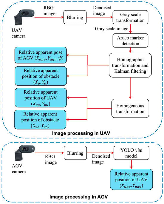
Figure 3.
Image processing operations in both vehicles for relative localization.
4.1. CNN-Based Localization of UAV
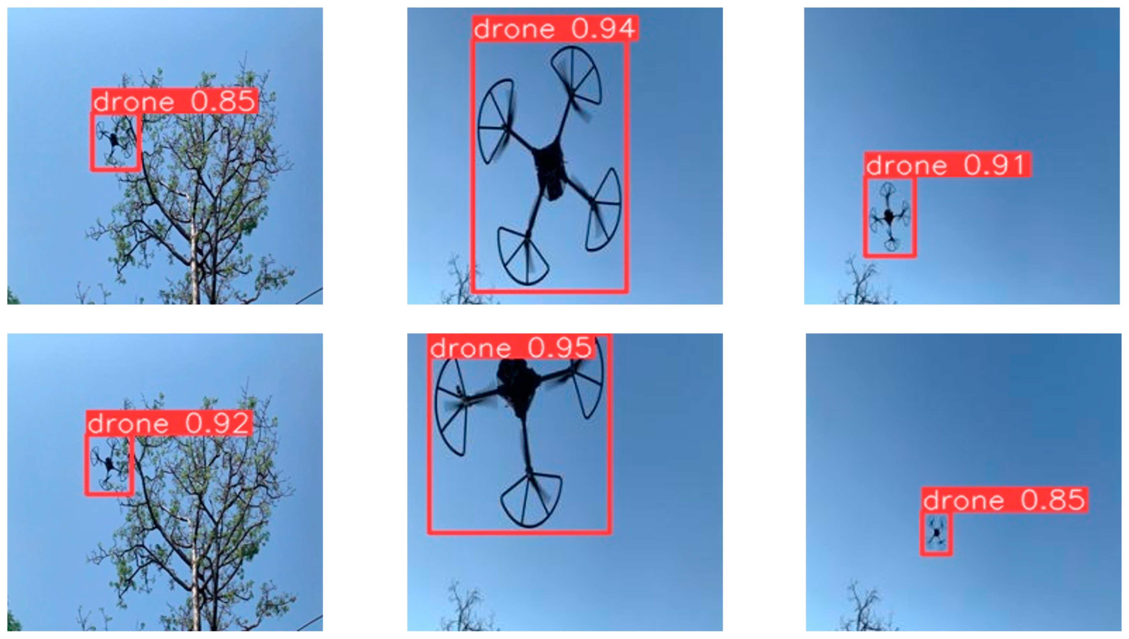
The AGV is mounted with a wide-angle camera, which is used to localize the drone/UAV for tracking it. We have adopted the YOLO v8 object detection architecture for localizing the drone in the image frame of the camera. The Ultralytics library is used to train YOLO v8n (nano model) on custom data (images of quadcopter drones). YOLO v8n is a lightweight object detection model with support for custom data training [31]. The size of the augmented dataset is 2000 images. The dataset is divided into 70% for training, 20% for validation, and 10% for testing. A precision of 0.998 is obtained on test data. mAP50 (mean average precision at IOU (Intersection Over Union) threshold of 0.5) and mAP50-95 (IOU threshold ranges from 0.5 to 0.95) values of 0.995 and 0.95 are obtained, respectively, on test data. Table 1 shows the metrics obtained on test data. Figure 4 shows a few test images. The trained model is tested outdoors by deploying it in the AGV before performing the actual tracking experiments. The inference time of the model is obtained around 5 ms, which ensures the real-time localization of the drone. Testing also verified that the model is accurate up to a drone altitude of 10 m altitude.

Table 1.
Metrics on test data.
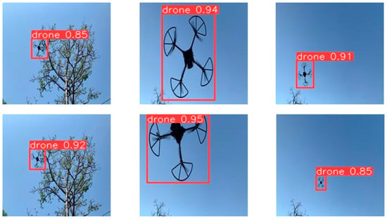
Figure 4.
Sample test images.
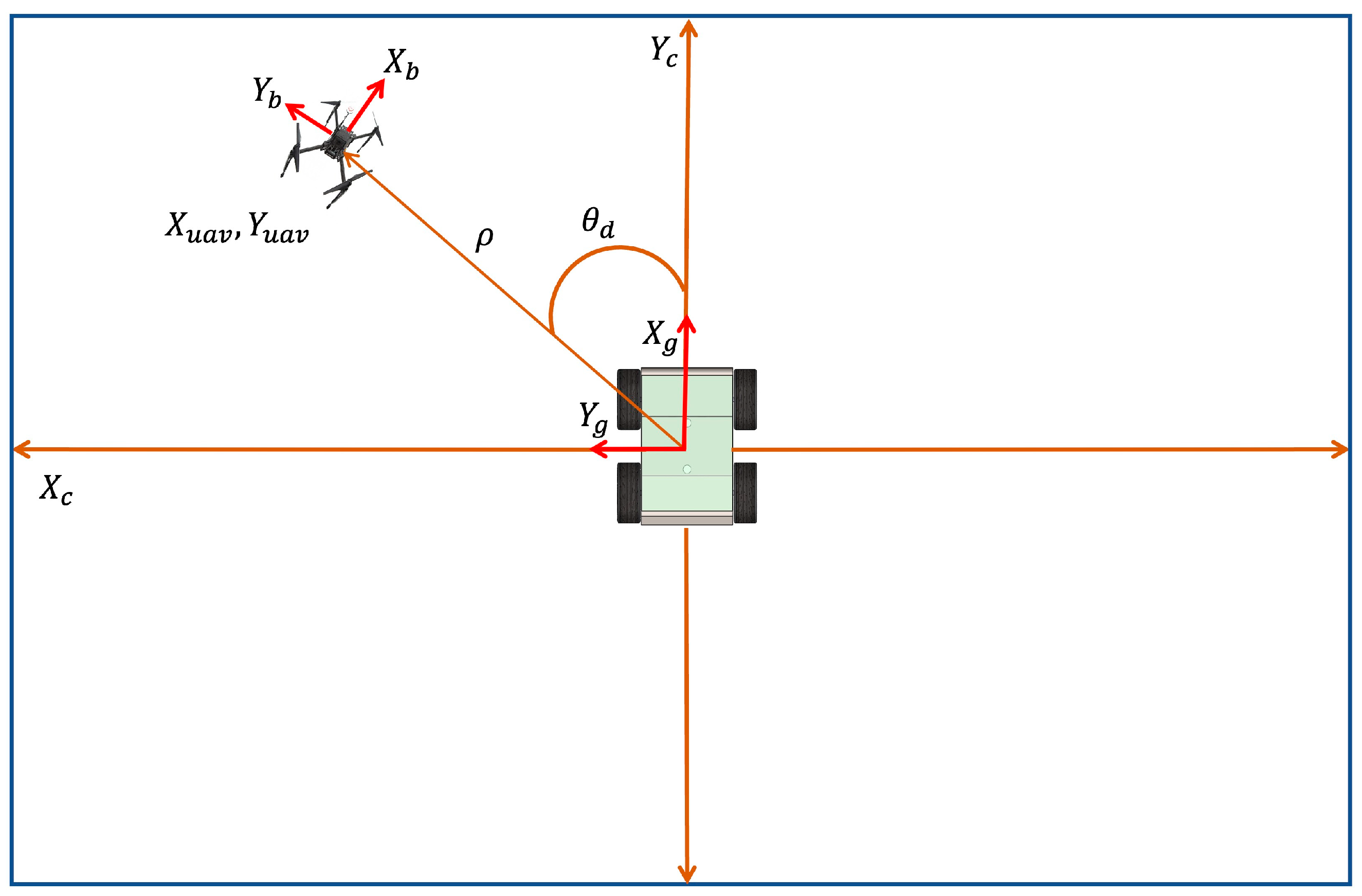
The centroid of the detected drone is calculated from the bounding box coordinates. The centroid is the relative apparent position of the drone with respect to the image plane of the AGV camera. The image plane is transformed to metric space from pixel space, and the origin is shifted to the center using (1) and (2). The localization of the UAV in the AGV camera is illustrated in Figure 5. The size of the input image for the deep learning model is 224 × 224. The centroid pixel coordinates of the UAV are considered for the same resolution. is the image plane of the AGV camera, is the body frame of the AGV, and is the body frame of the UAV, as shown in Figure 5. is the desired yaw angle of the AGV to reach the UAV. represent the apparent position of the UAV in the image plane, and are pixel coordinates of the UAV in the image plane of the AGV camera. and the apparent position of the UAV are inputs for the tracking controller, which is detailed in the next section.
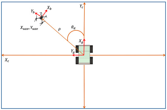
Figure 5.
Localization of UAV in AGV camera.
4.2. Marker-Based Localization of AGV and Obstacle
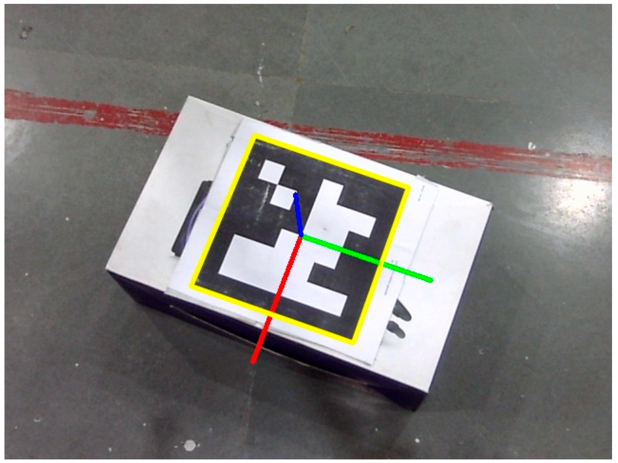
The UAV contains a down-facing monocular camera at its geometric center. Intrinsic parameters of the camera are obtained by camera calibration. ArUco markers of two different parameters are placed over the AGV and obstacle for unique localization using the UAV camera (Logitech USB camera). The AGV and obstacle are classified based on the parameters of markers detected. The OpenCV (Computer Vision) Python library is used for detecting the ArUco markers. The pose of the AGV is calculated by using an ArUco marker attached to the top of it. The pose of the obstacle is calculated similarly. Figure 6 shows the detection of the ArUco marker (obstacle) in the image plane of the UAV camera. The centroid coordinates of the yellow color bounding box are the apparent position of the obstacle, and the orientation of the body axes (in red, green, and blue colors) is the orientation of the obstacle. Assuming smaller roll and pitch angles of the UAV (camera), only the relative yaw angles of both the AGV and obstacle are computed from the body axes of the detected ArUco markers.
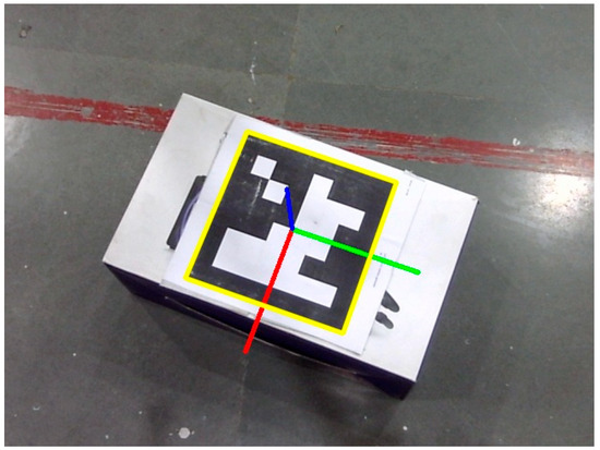
Figure 6.
Detection and localization of ArUco marker in image plane of UAV camera.
However, the roll and pitch angles of the UAV influence the position of the markers in the image frame, which is undesired. To overcome this problem, homographic transformation is implemented in this work using (3) [32]. It transforms the coordinates of a point from the oriented image plane due to the roll and pitch of the UAV to a virtual image plane that is parallel to the ground plane. and are pitch and roll angles of the UAV/camera frame. , are coordinates of the marker in the virtual image plane (different from the virtual plane of the AGV), and , are coordinates in the oriented/actual image plane. is the intrinsic matrix of the camera obtained by camera calibration. is the depth of markers in the actual camera frame, and is the depth of markers in the virtual camera frame along the optical axis. The terrain for the navigation of the AGV is flat in the present work; hence, the use of homographic transformation for the AGV camera is not considered. However, it should be considered if the terrain is uneven.
The image plane is transformed from pixel space to metric space by using (4) and (5) to simplify the controller design [4]. are pixel coordinates, is the pixel density of the image sensor, and are metric coordinates. The resolution of the camera is 640 × 480, and the pixel density is 40 ppcm (pixels per centimeter). Equations (4) and (5) are used to calculate the apparent pose of the AGV and the position of the obstacle in the image plane of the UAV camera. Figure 7a shows the relative localization of the AGV and obstacle in the image frame of the UAV. and are the body frames of the UAV and AGV, respectively. () and () are the apparent positions of the AGV and obstacle in the UAV image frame. The apparent positions of the UAV and obstacle are also obtained with respect to a virtual plane. The VP is fixed to AGV, and the origin coincides with the center of the AGV. Figure 7b shows the VP and localization of the obstacle and UAV corresponding to Figure 7a. is the VP of the AGV.

Figure 7.
(a) Localization of AGV and obstacle in UAV camera and (b) localization of UAV and obstacle in virtual plane of AGV.
and are the apparent positions of the UAV and obstacle in the virtual plane of the AGV, as shown in Figure 7b. (origin of image frame of the UAV camera) and are the apparent positions of the UAV and obstacle in the actual image plane of the UAV. is a homogeneous transformation matrix from the virtual plane () of the AGV to the image frame of the UAV and can be obtained as follows:
() is the pose of the AGV in the UAV image frame. The coordinates of and the apparent pose of the AGV are used to develop an obstacle avoidance controller for the UAV and a tracking controller for the AGV, respectively, which is detailed in the next section. The position of the obstacle in the virtual plane depends on the position and orientation of the AGV in the image plane of the UAV. It is the same in both the UAV image plane and the virtual plane of the AGV when (. The real distance of the obstacle from the AGV can be calculated using the pinhole model of the UAV camera.
where and are the distance of the obstacle from the AGV and the depth of the obstacle from the UAV with respect to the camera frame of the UAV, respectively. is the focal length of the camera. The maximum safety distance is when the obstacle lies at the corners or edges of the virtual plane. Hence, the maximum safety distance increases with the FOV or altitude of the UAV.
4.3. Kalman Filter Implementation
The proposed algorithm is majorly based on the data of the camera sensor. Sensor data contains noise in outdoor conditions. Thus, a linear Kalman filter is implemented for noise elimination and robust position estimation of the AGV and obstacle in the image frame of the UAV. The state of the system is , and output is ; the state and output equations are [33]
where is a discrete time instant, is the state of the system, A is the state transition matrix, is the output vector, is the measurement/observation matrix, is the process noise vector, which is considered as zero, and is the measurement noise vector. Matrices and can be written as
is a discrete time interval. According to the Kalman filter algorithm, the error covariance matrix () and state are propagated using the model of the system before the measurement arrives.
is a process noise covariance matrix. The Kalman gain matrix can be updated as
is Kalman gain, and is the measurement noise covariance matrix. Then, the state update follows the measurement () arrival:
is propagated by (13) and (17). Then, is used to compute using (13), and the process repeats until convergence. A similar procedure is followed for both AGV and the obstacle.
5. Controller Design
The total task can be divided into tracking and obstacle avoidance. Tracking is performed by the AGV, and obstacle avoidance is performed by the UAV. So, a tracking controller is developed for the non-holonomic AGV to track the UAV, and an obstacle avoidance controller is designed for the UAV. Sliding mode control theory is gaining popularity in robot motion control [23,34,35,36,37]. It is easy to implement in both linear and non-linear systems. Thus, we have implemented the sliding mode method for designing controllers.
5.1. Tracking Controller for AGV
The tracking task between the UAV and AGV can either be the UAV tracking the AGV or vice versa. The AGV tracking the motion of the UAV is considered in this work for the navigation of the AGV. A sky-facing wide-angle camera is mounted to the AGV for localizing the UAV as discussed in the previous section. The tracking controller for the AGV is developed based on the apparent position and velocity of the UAV in the AGV image frame. The apparent velocity is the rate of change in the apparent position in the image frame. As shown in Figure 5, is the magnitude of the apparent position of the drone. The position and angular errors are defined as
is the actual apparent position of the AGV (origin of the image frame), is the desired position, which is the apparent position of the drone in the image frame, which is shown Figure 5. is the current yaw angle of the AGV, and is the desired yaw angle which is calculated from the apparent position of the drone as shown in Figure 5.
Proportional sliding surfaces are considered as follows [4]:
and are positive constants. Taking the derivative of (21) and considering the hyperbolic tangent reaching law [31],
A control law for the linear velocity of the AGV can be obtained as
where is a positive constant. is positive and depends on the apparent size of the drone in the image frame. Similarly, a control law for angular velocity can be obtained as
is a positive constant. Heading control or angular velocity control contains two operational modes. When the apparent position of the UAV lies above a certain threshold, is calculated from the apparent position of the UAV. If it lies below the threshold (close to the origin of the image frame), then is calculated from the direction of the velocity of the drone in the body frame of the AGV. Hence, this ensures the heading of the AGV is always towards the motion of the UAV. The direction of the UAV velocity in the body frame of the AGV is calculated from (25).
The desired yaw angle of the AGV is calculated as per (26).
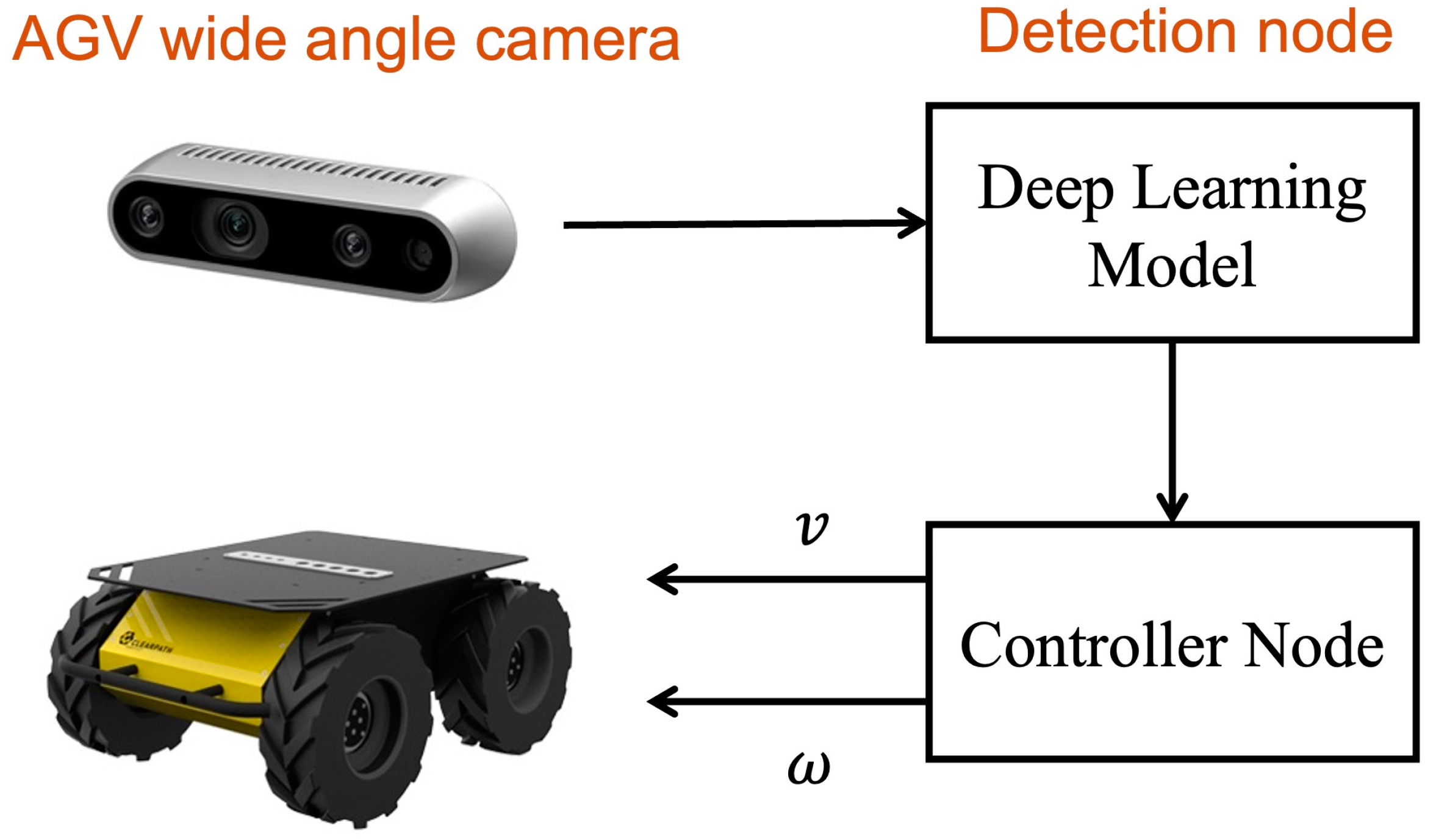
is the rate of change in the position of the drone in the image frame of the AGV, which can also be treated as the apparent velocity of the drone. Figure 8 shows the overall control architecture and communication among ROS nodes in the AGV. The detection node receives data from the wide-angle camera and localizes the drone in the image frame if presented in the FOV. The controller node receives the centroid coordinates and apparent velocity of the drone. Then, the controller node computes control commands (linear and angular velocities) as discussed above.
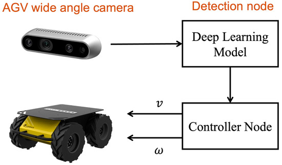
Figure 8.
Control architecture for AGV to track UAV.
Stability Analysis
Consider the following Lyapunov function [37]:
Taking the derivative of the Lyapunov function,
Substituting (22) in (28),
Since the rate of change in the Lyapunov function is negative definite, the control law ensures the stability of the system. Similarly, the stability of the control law of angular velocity can be verified.
5.2. Collaborative Obstacle Avoidance Controller
The proposed obstacle avoidance method is verified with a reactive strategy. A reactive strategy is considered to develop obstacle avoidance for the AGV. It is a mapless technique, as discussed earlier. However, the method can be extended to map-based navigation of the AGV guided by the UAV. The reactive method is driven by controlling the velocity of the AGV to avoid obstacles [19,20]. This controller is designed for the AGV, but control actions are taken by the UAV. As discussed earlier, the task of the UAV is to avoid the virtual obstacle (orthographic projection of physical obstacle) in its plane of motion. A virtual velocity controller is designed for the AGV based on the apparent position of the obstacle in the VP. Then, the virtual velocity of the AGV is transformed to the body frame of the UAV. This velocity directs the UAV away from the obstacle. Figure 7 shows the positions of the UAV and obstacle in the virtual plane of the AGV. () is the position of the obstacle in the VP. The virtual lateral velocity of the AGV is calculated for obstacle avoidance. A sliding mode controller for the lateral virtual velocity of the AGV is designed. The aim of this controller is to increase to direct the AGV away from the obstacle.
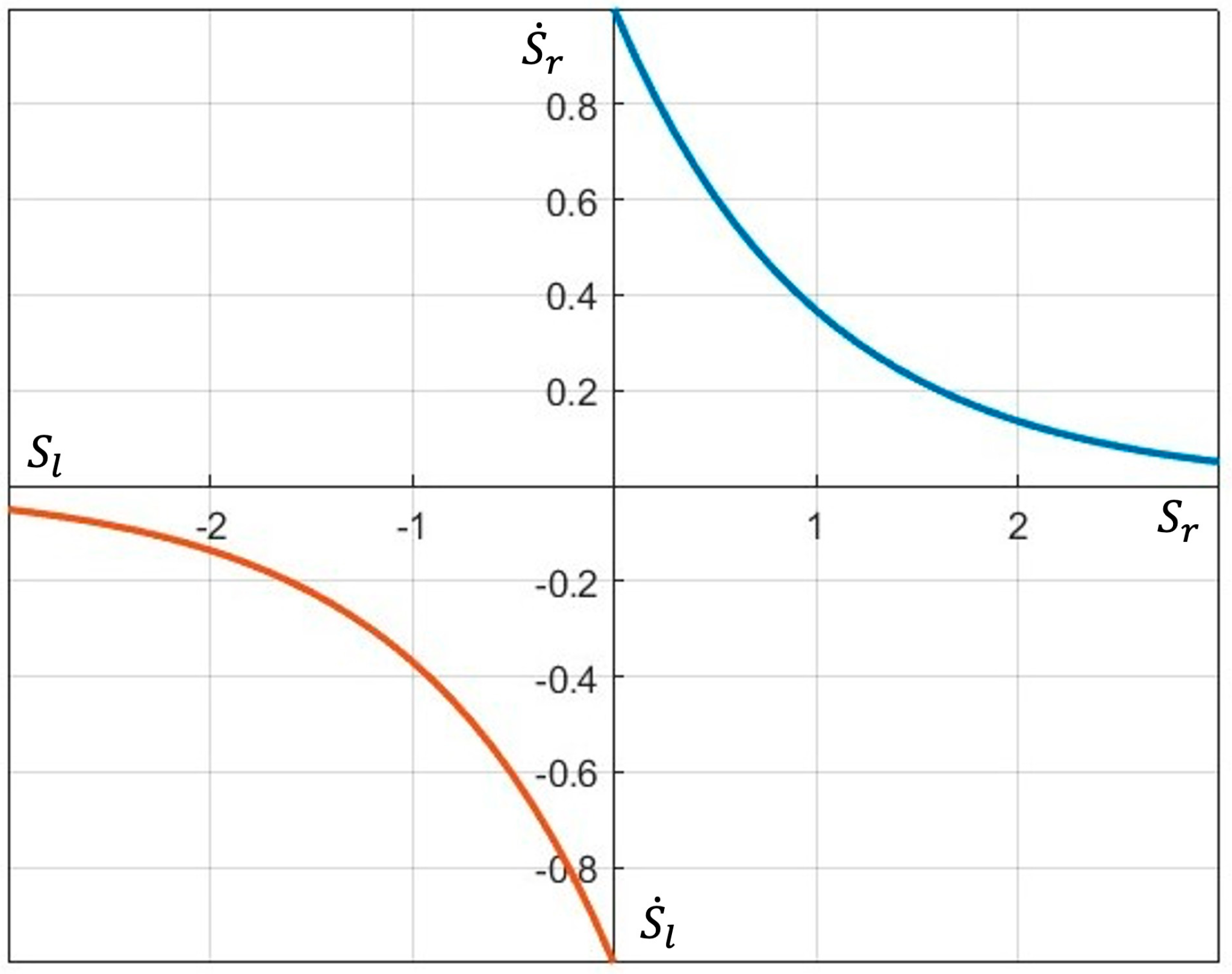
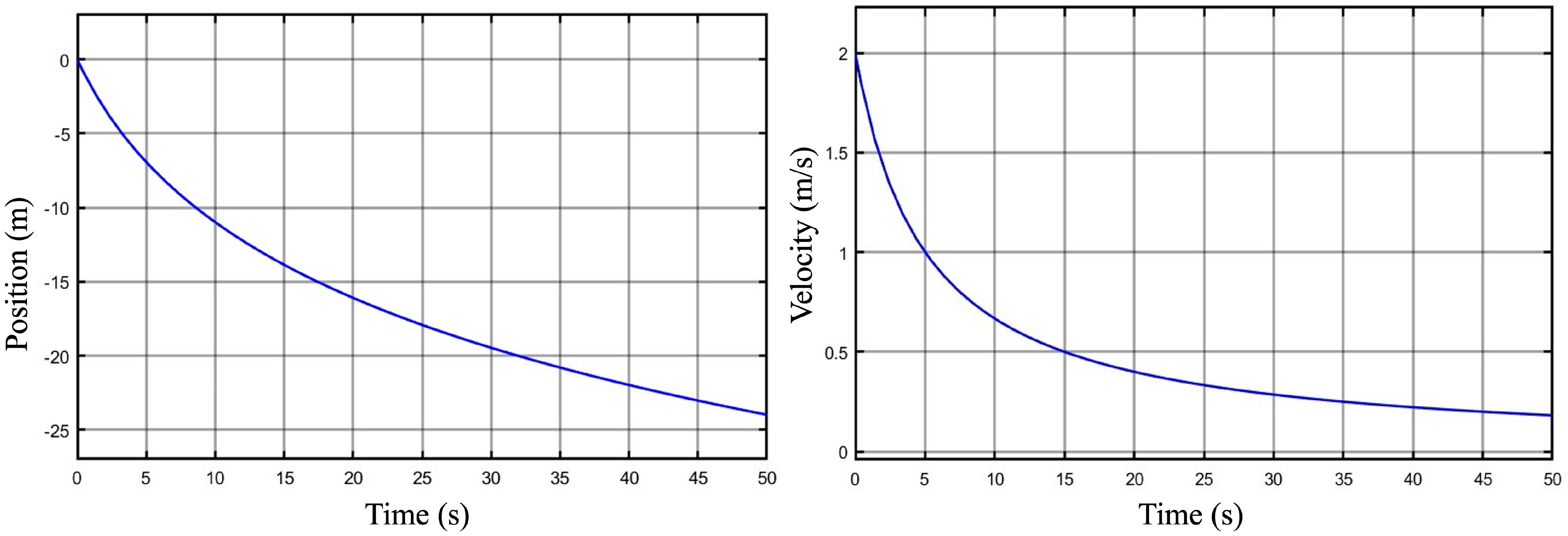
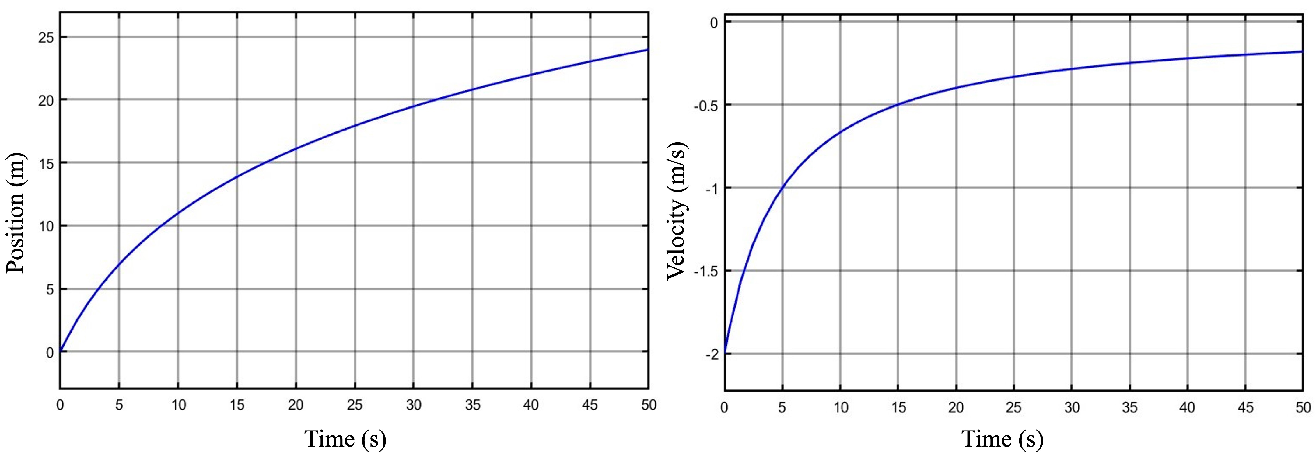
where is the error and is a sliding surface function proportional to the error. When the error is negative, the control action must be along the negative direction. If the error is positive, the control action must be along the positive direction. The objective is to minimize the error (31). Figure 9 shows the variation in the reaching law (rate of change in sliding surface). Obtaining an analytic function for such a reaching law may not be possible. Thus, the axis is divided into two domains. is the right-side domain, and is the left-side domain. According to (31), the velocity of the AGV must be along the negative axis for to be positive. Thus, the following reaching law is proposed to achieve this:
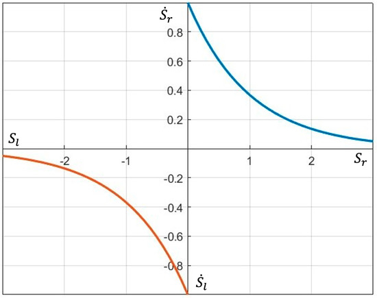
Figure 9.
Reaching law.
Control laws for the rate of change in the apparent position of the obstacle can be obtained as
Control laws for the virtual velocity of the AGV can be obtained as
The virtual velocity of the AGV is transformed to the UAV to avoid virtual obstacles. The AGV tracks the UAV to avoid physical obstacles. The velocity control law for the UAV to avoid a virtual obstacle can be obtained as
is the velocity of the UAV, is the rotation matrix from the virtual plane of the AGV to the image plane of the UAV, and ( and ) is the virtual velocity of the AGV.
5.2.1. Stability Analysis
Consider the following Lyapunov function:
Taking the derivative of the Lyapunov function,
Substituting (33) in (42),
Thus, the rate of change in the considered Lyapunov function is negative definite for the positive set of the sliding surface function. Similarly, stability can be verified for the negative set. Hence, the control law ensures the stability of the system for the entire range of the sliding surface function.
5.2.2. Simulations
Figure 8 shows the variation in the position of the obstacle and the virtual velocity of the AGV. The initial position of the obstacle is close to zero and towards the negative axis. The controller takes action to increase the offset of the obstacle, which can be seen in Figure 10. The virtual velocity of the AGV gradually reaches zero when the obstacle is sufficiently far from the UAV. Figure 11 shows the performance of the controller when the initial position of the obstacle is zero. The controller output is high as the obstacle is close to zero and reaches zero gradually as the obstacle position increases.
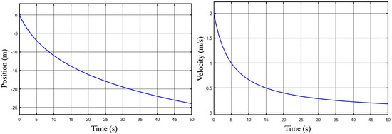
Figure 10.
Variation in position of obstacle in VP and controller output.
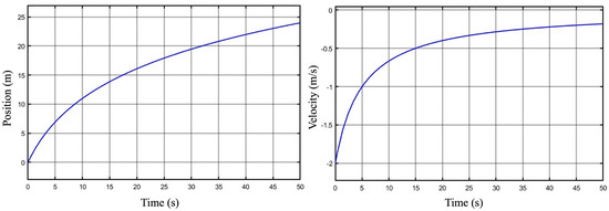
Figure 11.
Variation in position of obstacle in VP and virtual velocity of AGV.
The tracking controller of the AGV and the obstacle avoidance controller of the UAV function in parallel to achieve the safe navigation of the AGV. The overall control action can be explained as follows: One of the conditions that the tracking controller of the AGV achieves is
is the unit vector of the body axis of the AGV along the longitudinal direction, and is the velocity of the UAV in the body frame of the AGV. This condition shows that AGV continues to head along the motion of the UAV during tracking. The obstacle avoidance controller of UAV works to achieve the following condition:
Whenever the UAV detects an obstacle in the VP of the AGV, the obstacle avoidance controller commands the UAV to move along the or axis to satisfy (46) according to the obstacle avoidance control laws. Parallelly, the tracking controller of the AGV continues to satisfy (45). When an obstacle is detected in the FOV of the UAV, the UAV continues to satisfy (45), and the AGV attempts to achieve (46). Hence, both conditions are achieved simultaneously while AGV avoids obstacles.
6. Hardware and ROS Architecture
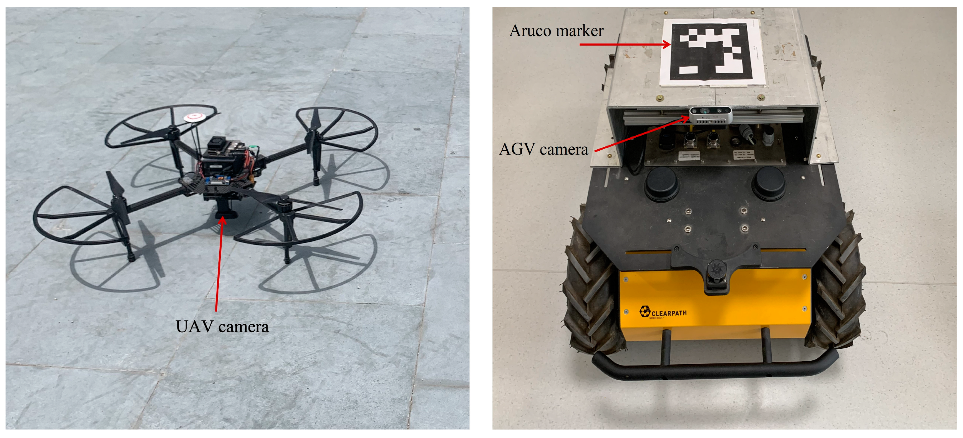
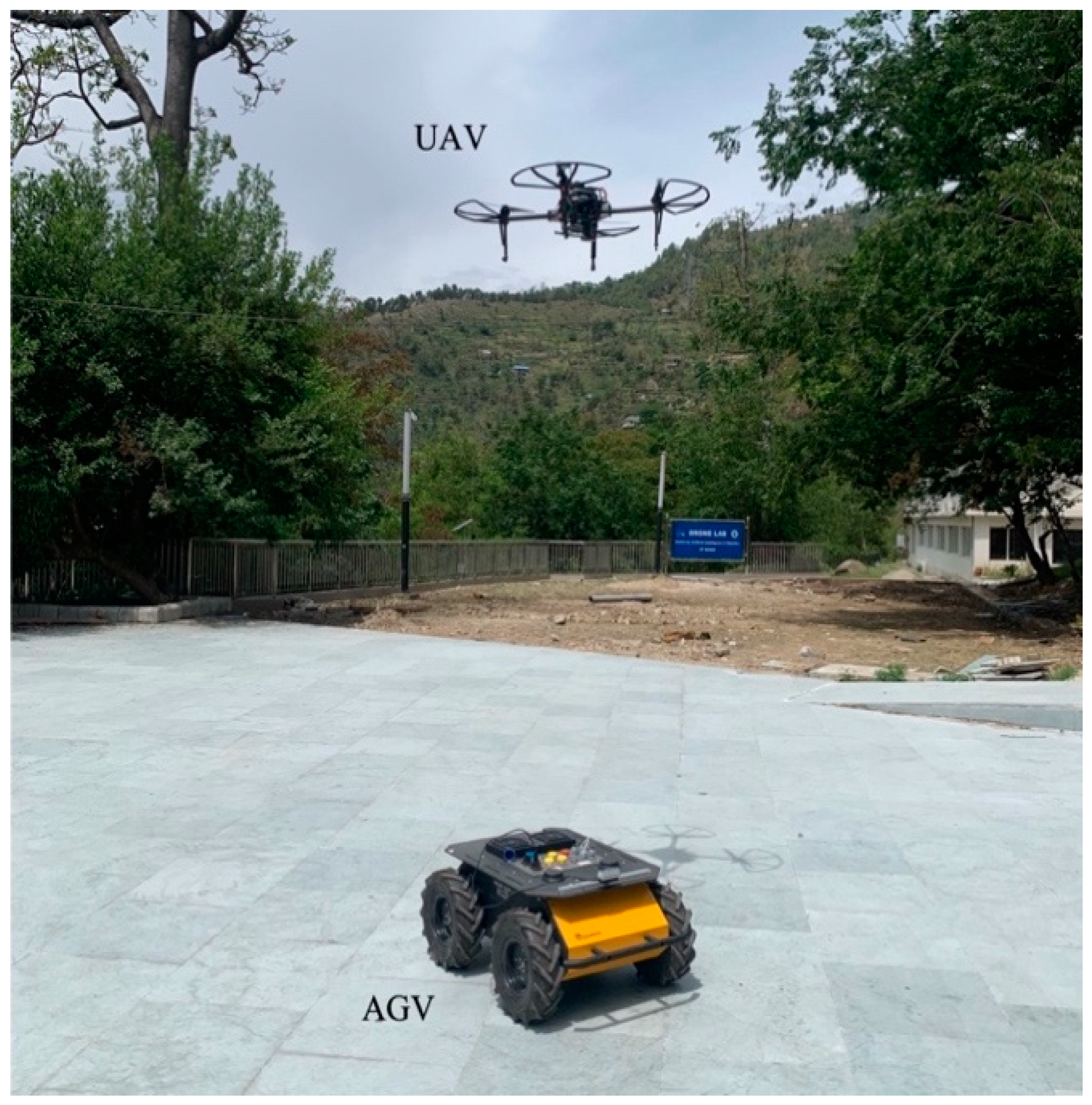
The UAV is a DJI Matrice100 and the AGV is a Clearpath Husky A200. The UAV contains an IMU (Inertial Measurement Unit), gyroscope, magnetometer, GPS, and an externally attached low-cost USB (Universal Serial Bus) Logitech camera. The AGV contains an IMU, a gyroscope, and a magnetometer. It is a non-holonomic vehicle that works on a skid-steering technique. The ROS package provided by Clearpath enables the user to command linear and angular velocities of the AGV. Similarly, for the UAV, the ROS package is provided by DJI. High-level motion commands (position, velocity) can be given to the UAV. Figure 12 shows both vehicles. An ArUco marker is placed over the AGV for localization using the camera of the UAV.
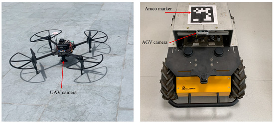
Figure 12.
Hardware.
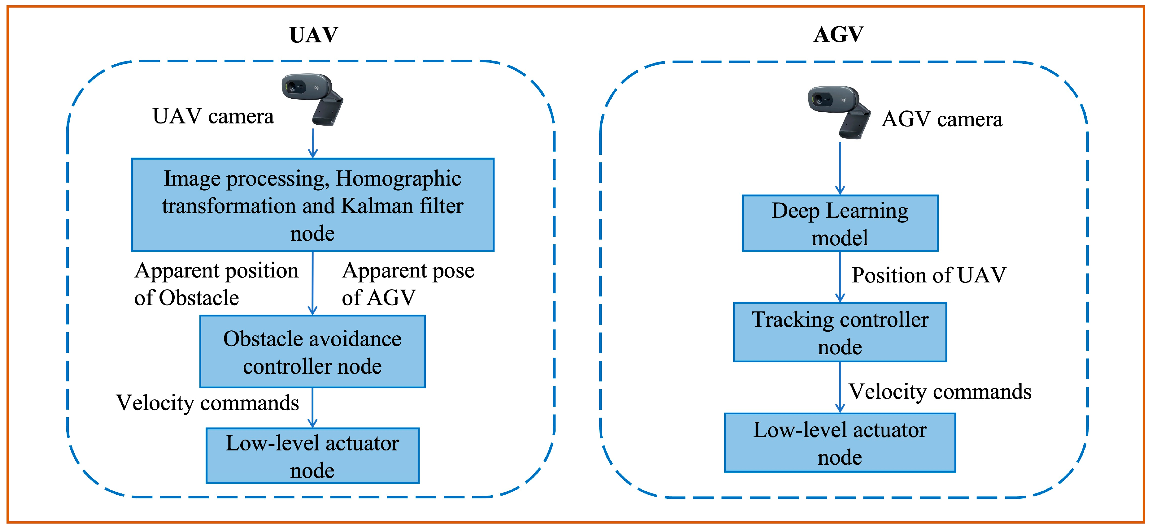
The Jetson Xavier NX controller is used with the UAV, which runs on Ubuntu 20.04 with ROS Noetic. The AGV also runs on ROS Noetic with Ubuntu 20.04. Figure 13 shows the data transfer among the various ROS nodes of the two-agent system. The UAV calculates the apparent pose of the AGV and the apparent position of the obstacle after performing a homographic transformation of pixel coordinates. Then, the obstacle avoidance controller calculates control commands for the UAV to virtually avoid obstacles. The AGV obtains the apparent position of the UAV using its sky-facing camera. The tracking controller receives the apparent position of the UAV and computes the control commands (linear and angular velocities) for the AGV to track the UAV. Hence, both agents are independently functioning without communicating with each other.
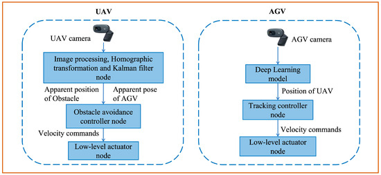
Figure 13.
ROS node commutation in both agents.
The internal flight controller of the drone ensures its stability under a range of wind disturbances. Our goal is to validate the proposed non-communicative navigation technique for AGV. So, we developed high-level controllers (velocity control) for the motion of UAVs and AGVs. The internal flight controller takes the velocity commands and controls the low-level commands such as forces and torques. And we assumed good environmental conditions for the validation of the method. So, flight stability is majorly left to the flight controller. However, it is required to ensure the applicability of the proposed method under such disturbance conditions. It is possible to ensure stability by developing a low-level controller for the motion of the drone. And it is planned to extend the work in this direction.
7. Experimental Results
The experimental results are presented in two subsections. Initially, we verified the performance of the tracking controller solely with tracking experiments. Then, the collaborative obstacle avoidance control of the system was experimentally verified along with the AGV tracking the UAV.
7.1. Tracking Experiments
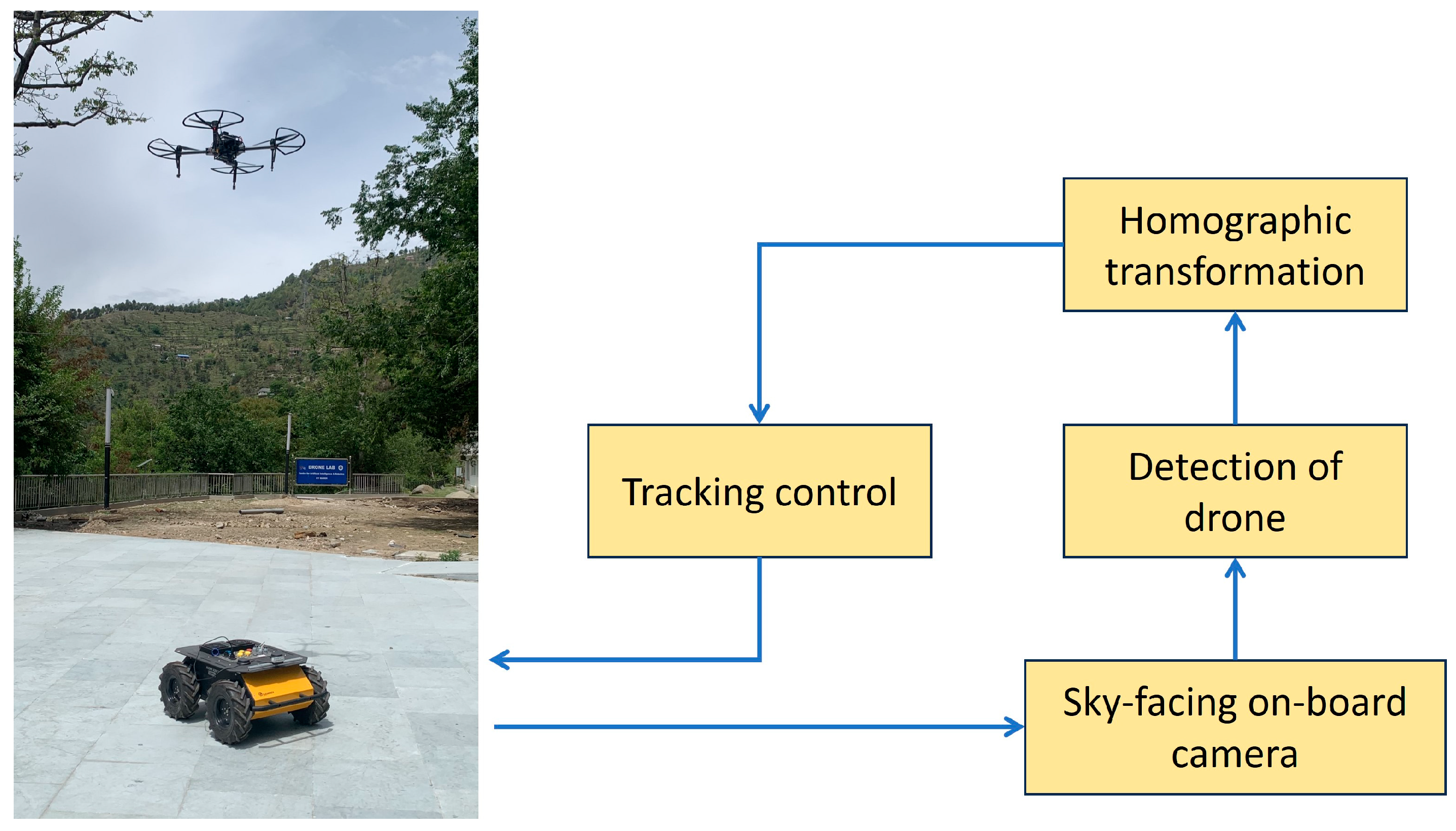
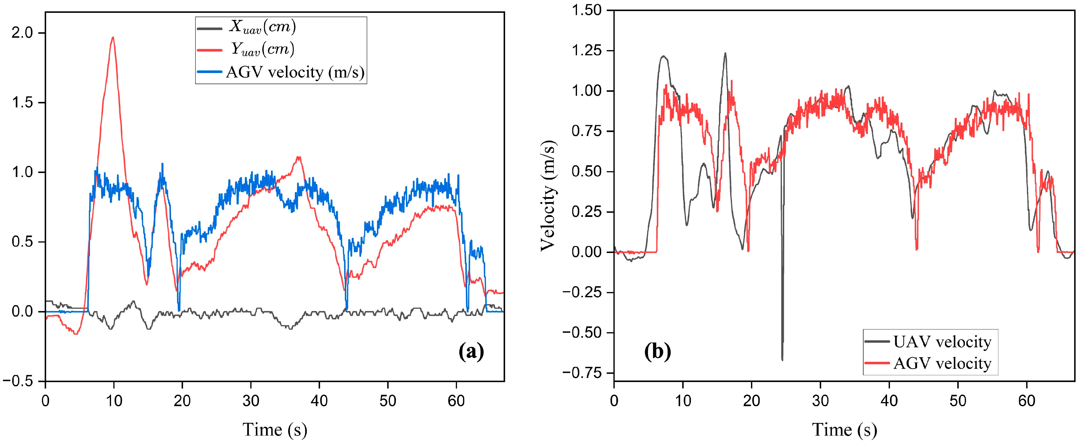
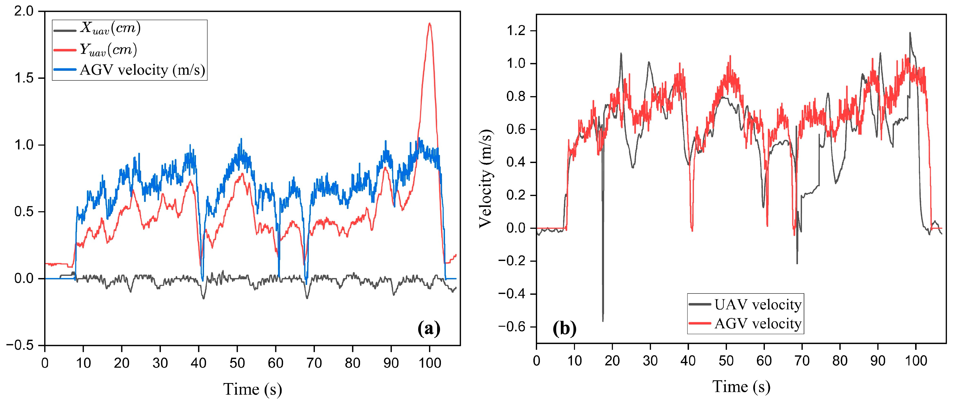
Figure 14 shows the overall tracking strategy. After the UAV is detected, homographic transformation is applied to overcome the effect of the roll and pitch angles of the AGV on the apparent position of the UAV. Figure 15 shows the AGV and UAV during tracking experiments. The aluminum mount is removed for performing tracking experiments. The UAV is manually operated with random velocity commands. The AGV localizes UAVs with its sky-facing wide-angle camera and tracks the projection of the center of the UAV on the ground plane. Figure 16a shows the variation in the position of the drone in the AGV image frame and the linear velocity of the AGV. It is clearly evident that the position of the UAV along the direction of the image frame is close to zero. This indicates the performance of the angular velocity control of the AGV. The angular velocity controller tries to keep the drone on the to minimize , which in turn minimizes . This can be understood from Figure 5. If AGV minimizes , it brings the position of the drone onto the axis. Hence, the angular velocity controller is showing acceptable performance. Figure 16b shows the variation in the velocity of the UAV (along the axis of the AGV) and AGV. The velocity of the UAV is transformed to the body frame of the AGV for comparison. It can be observed that the linear velocity of the AGV overlaps with the UAV velocity, which indicates the performance of the tracking controller. Hence, the AGV is satisfactorily tracking the motion of the UAV from these results. An experimental demonstration is attached (Video S1). Figure 17 shows the result of another tracking experiment. Similar performance can be observed.
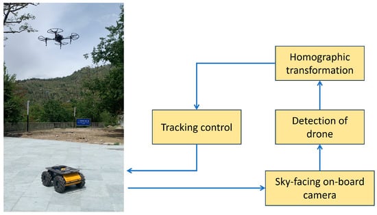
Figure 14.
Overall non-communicative tracking strategy for AGV.
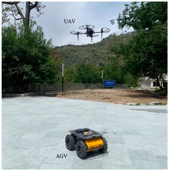
Figure 15.
Image taken during tracking experiment.
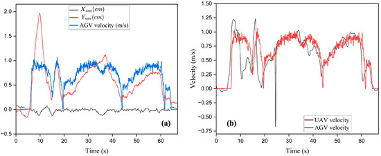
Figure 16.
(a) Apparent position of UAV and linear velocity of AGV and (b) variation in velocity of UAV and AGV during tracking.
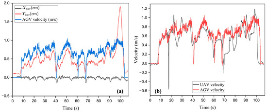
Figure 17.
(a) Apparent position of UAV and linear velocity of AGV and (b) variation in velocity of UAV and AGV during tracking.
The above results show that the AGV is able to track UAVs without communicating with them. This tracking strategy can be implemented in outdoor and GPS-less conditions. Hence, the AGV can continuously track UAVs in GPS-less and outdoor conditions to support the longer missions of UAVs. A recent paper [23] reports path following by a ground-vehicle-assisted aerial vision sensor. The aerial vehicle/UAV detects the path and communicates the path points to the AGV in real time. A non-linear sliding mode controller is designed for the AGV to track the path continuously provided by the UAV. It is also possible to solve this problem with the UAV leader and AGV follower task. The UAV can detect a path using its down-facing camera and can follow it at a certain altitude. And the role of the AGV is to track the motion of the UAV to follow the same path. The communication requirement can be eliminated with this method. This method may ensure the safety of the task, especially in outdoor conditions where communication failures can occur. The tracking task of the AGV is exploited for its navigation in the present work instead of path following. The experimental results of the navigation of the AGV are discussed in the next section.
7.2. Obstacle Avoidance Experiments
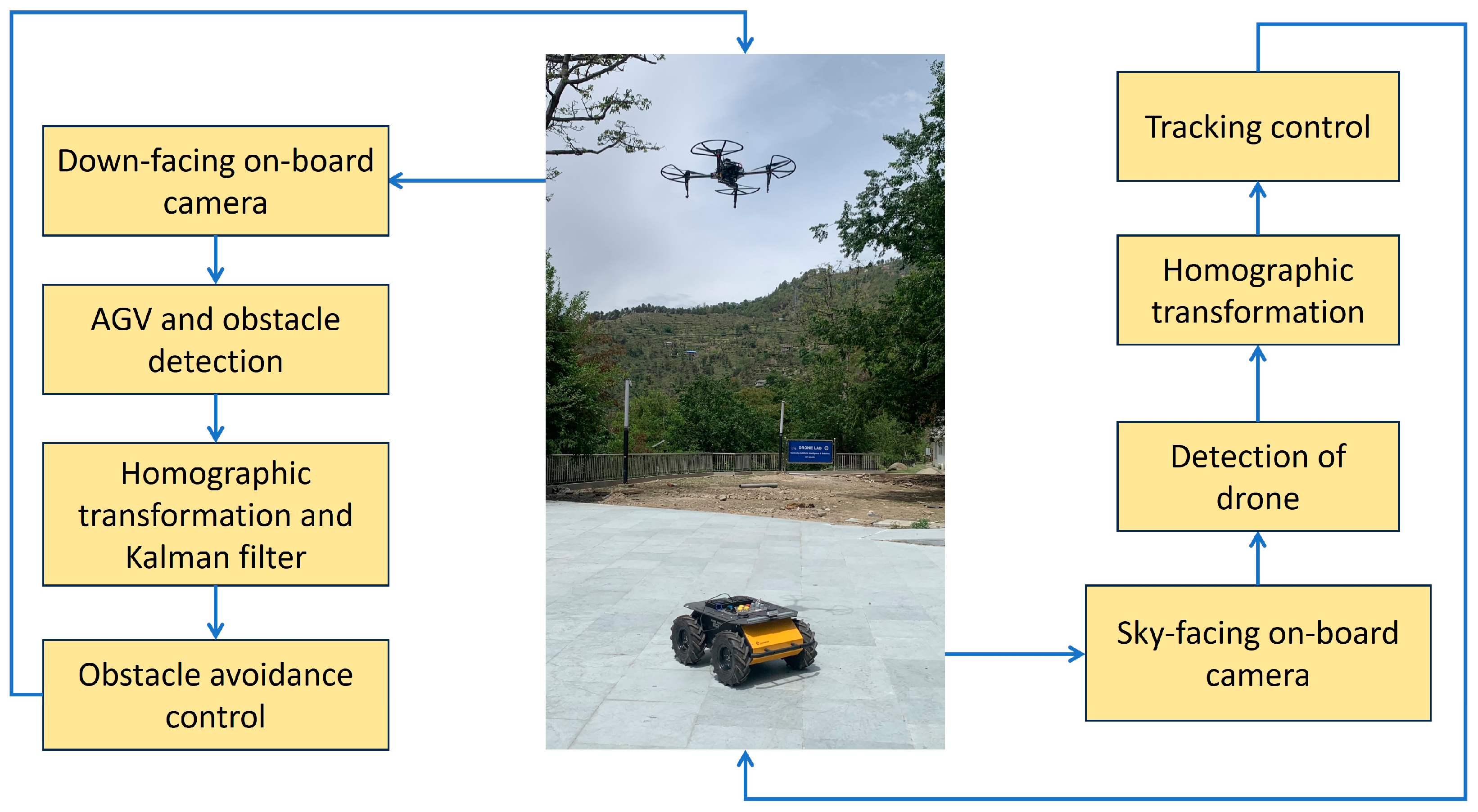
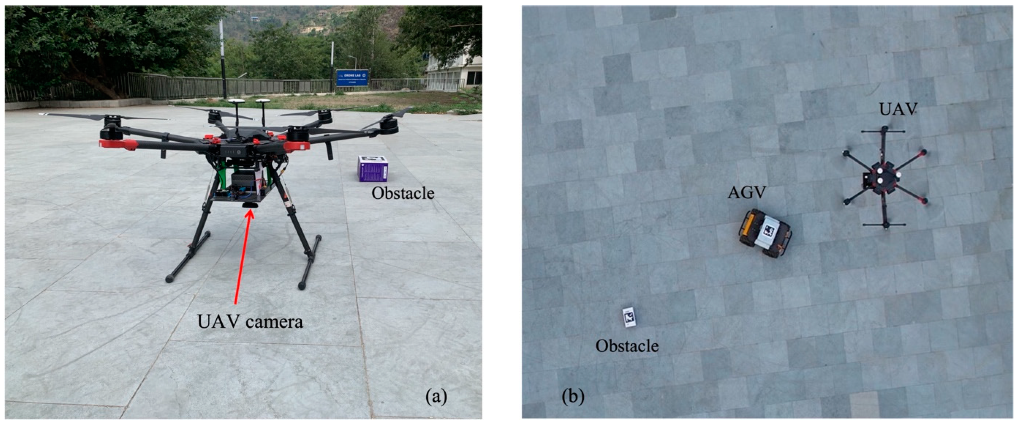
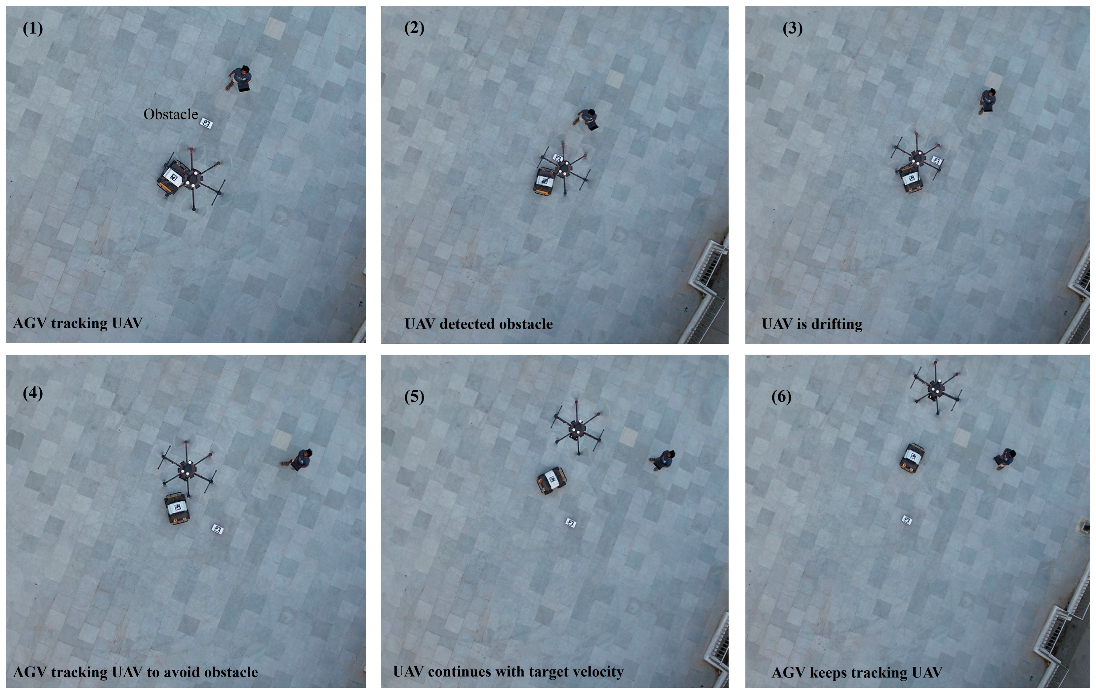
Figure 18 shows the overall strategy for non-communicative navigation of the AGV. It is clear that there is no communication link between both agents. Each vehicle independently executes its respective tasks. The UAV performs localized obstacle detection using a down-facing camera and performs virtual obstacle avoidance. The AGV detects the UAV using its sky-facing camera and performs tracking tasks. Figure 19 shows the UAV (DJI Matrice 600, Shenzhen, China) with a down-facing onboard camera and an image taken during obstacle avoidance experiments. A hexacopter was used for these experiments due to the unavailability of a quadcopter. Nvidia Jetson AGX Orin is the onboard computer of the hexacopter. The AGV and obstacle are uniquely identified by the UAV by their ArUco marker parameters as discussed earlier. The UAV is given a target velocity in its body frame. The AGV localizes the UAV using its onboard camera and tracks it as discussed in the tracking experiment section. When the UAV localizes an obstacle in its down-facing camera, the obstacle avoidance controller takes action. After successfully guiding AGV to avoid the obstacle, the UAV continues with its target velocity, which is initially commanded. And the AGV keeps tracking the UAV. Figure 20 shows aerial image instances during an obstacle avoidance experiment. The UAV is given a target forward velocity, and the AGV keeps tracking the UAV. Instance 1 shows the AGV tracking the UAV. In the second instance, the UAV detects an obstacle, and the obstacle avoidance controller takes action. The UAV drifts laterally (along the or axis of the AGV) as shown in instance 3; the AGV continues to track the UAV. Instances 4 and 5 show successful obstacle avoidance of the AGV. In instance 5, the apparent position of the obstacle reaches beyond a threshold value. Then, the UAV keeps moving with its target forward velocity, and the AGV keeps tracking it.
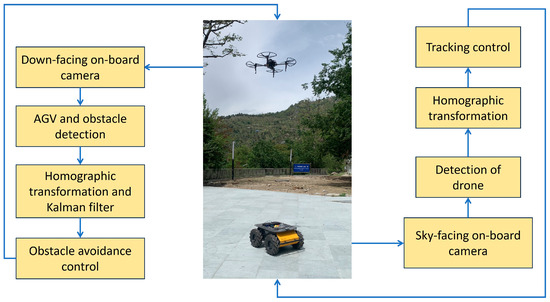
Figure 18.
Overall strategy for non-communicative navigation of AGV assisted by UAV.
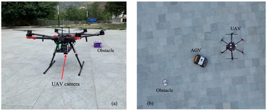
Figure 19.
(a) UAV with down-facing camera and (b) obstacle avoidance experimentation.
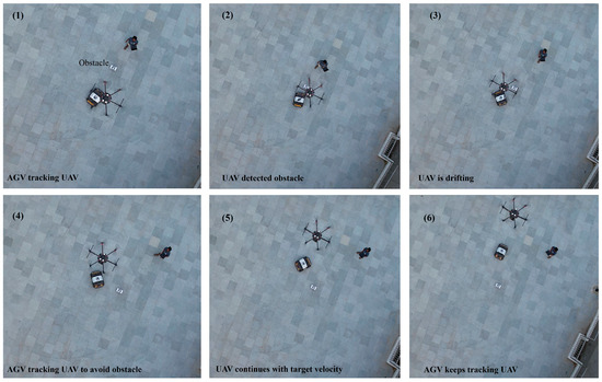
Figure 20.
Aerial image instances during obstacle avoidance.
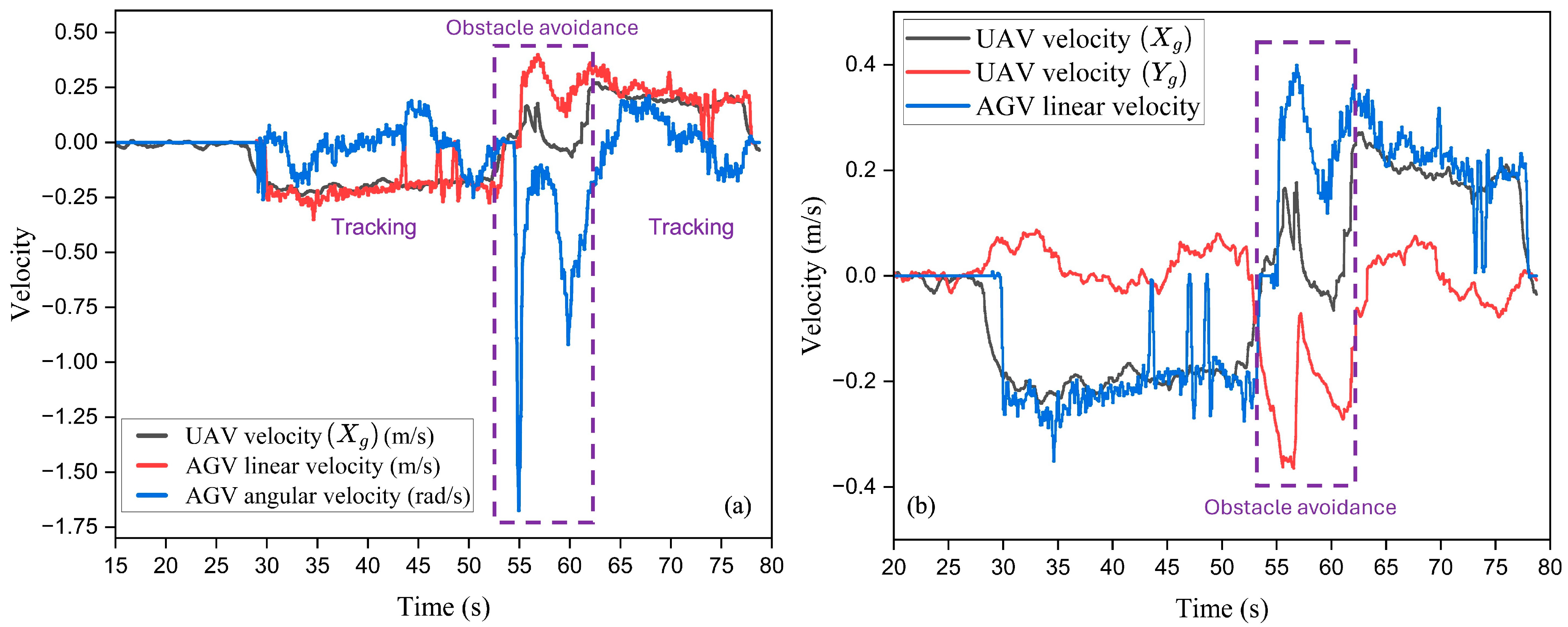
Figure 21 shows the velocity of the UAV (along the of the AGV) and AGV (linear and angular) during tracking and obstacle avoidance. The tracking and obstacle avoidance durations are highlighted in Figure 21a. Figure 21b shows the velocity of the UAV in the body frame of the AGV and the linear velocity of the AGV. A target forward velocity of 0.22 m/s is commanded to the UAV. The AGV keeps tracking the UAV from 25 seconds to 50 seconds in the absence of an obstacle. It can be clearly observed in Figure 21 that the AGV linear velocity overlaps with the UAV velocity. The velocity of the UAV along the axis of the AGV is close to zero during tracking, which can be seen in Figure 21b. When an obstacle is detected by UAV, it drifts along the or axes of the AGV as per the obstacle avoidance control algorithm. So, there is a sudden rise in the velocity of the UAV along and a fall along . This can be observed between 50 and 55 s, when an obstacle is detected by the UAV. To track the lateral drift of the UAV, there is a jump in the angular velocity of the AGV. It can be observed in Figure 21a. After successfully guiding the AGV to avoid the obstacle, the UAV keeps moving with its target forward velocity again. And AGV keeps tracking it as shown in Figure 21 after approximately 62 s.
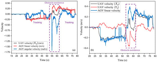
Figure 21.
(a) Velocity of the UAV and AGV in the body frame of the AGV and (b) linear velocity of the UAV and AGV in the body frame of the AGV during the obstacle avoidance experiment.
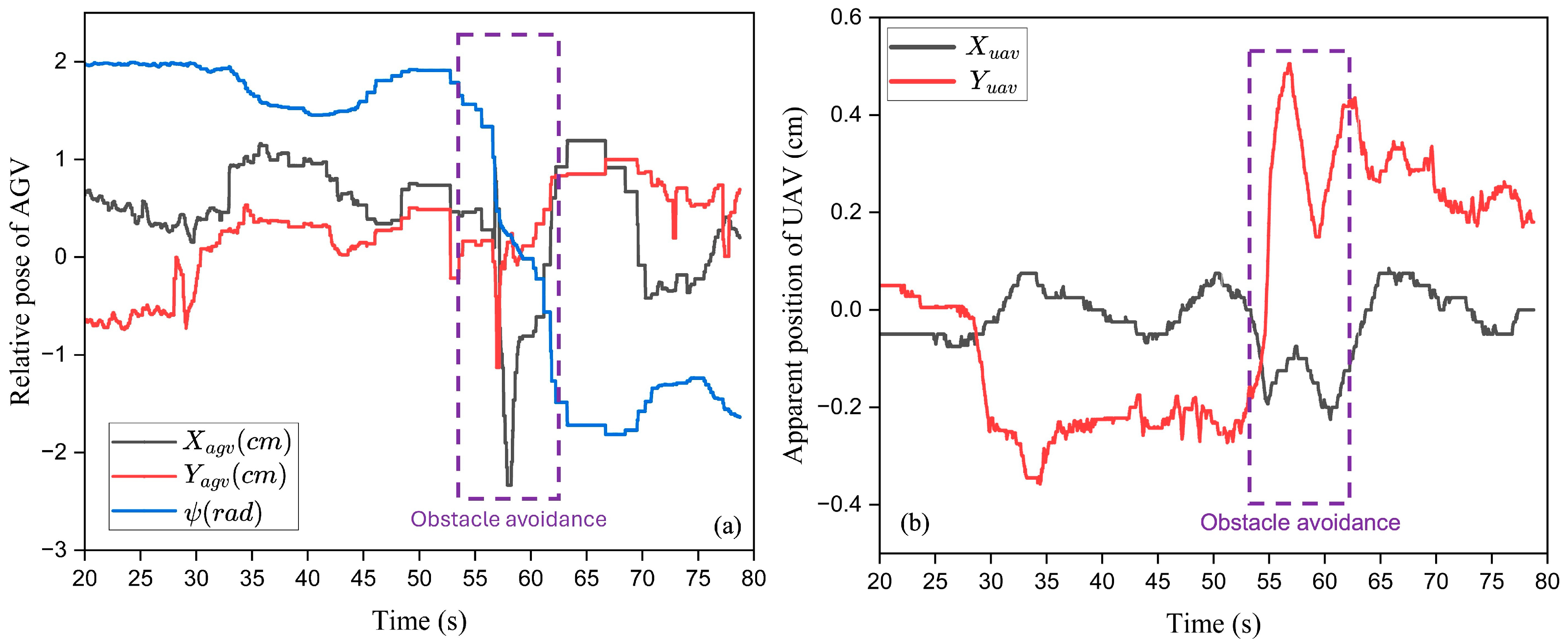
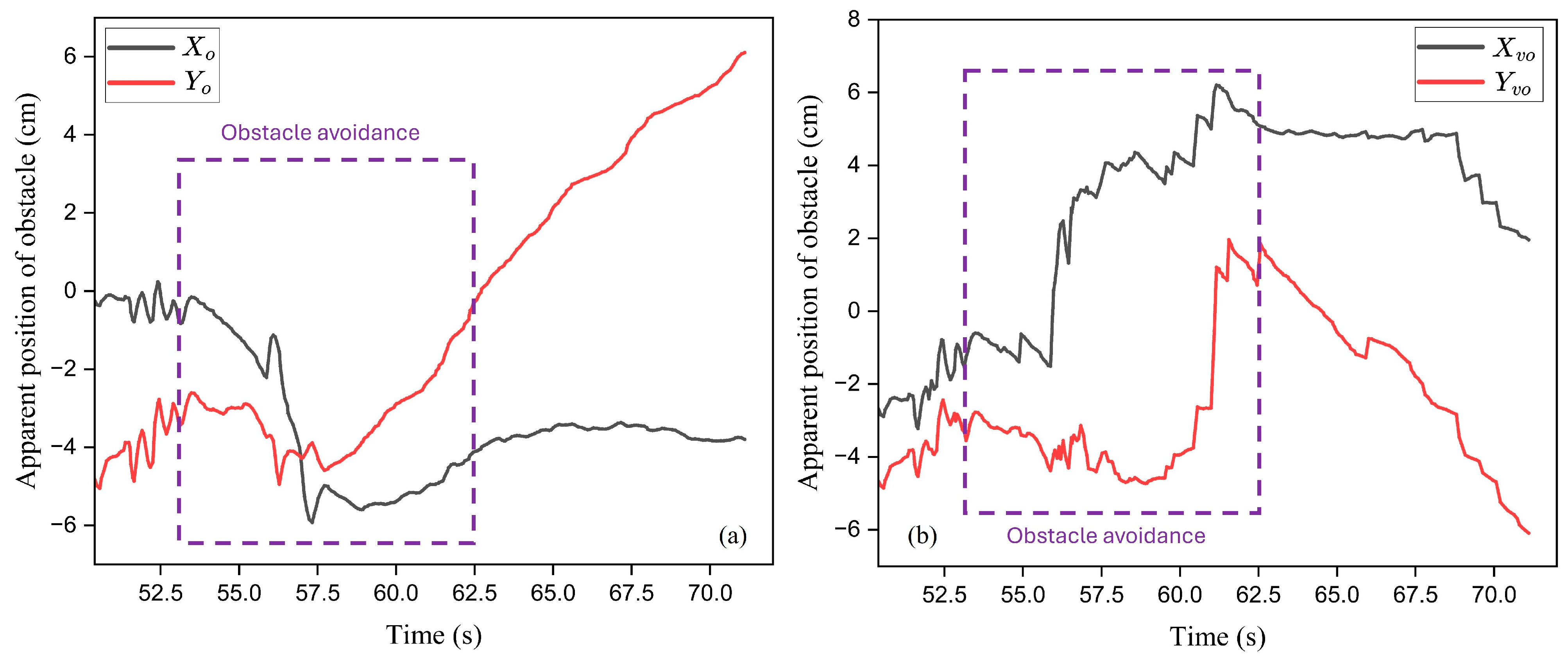
Figure 22 shows the variation in the apparent pose of the AGV in the image frame of the UAV camera and the apparent position of the UAV in the image frame of the AGV camera. During tracking, the yaw angle of the AGV is mostly flat and drops during obstacle avoidance, as shown in Figure 22a. Figure 22b shows the apparent position of the UAV in the image frame of the AGV camera. There is a sudden rise in the apparent position of the UAV along the axis due to the lateral drift of the UAV during obstacle avoidance. Figure 23 shows the variation in the apparent position of the obstacle in the image frame of the UAV and the virtual plane of the AGV during obstacle avoidance. The apparent position of the obstacle along the axis of the UAV image frames increases due to the drift of the UAV which can be seen in Figure 23a. After obstacle avoidance, the component of the obstacle gradually increases, keeping the component almost flat, as shown in Figure 23a. This is due to the forward motion of the UAV after obstacle avoidance. Figure 23b shows the apparent position of the obstacle with respect to the virtual plane of the AGV during obstacle avoidance. The apparent position of the obstacle along the axis keeps increasing after obstacle avoidance due to the tracking motion of the AGV. After 70 seconds, the obstacle disappears in the image frame of the UAV. Multiple trials have been performed to ensure the repeatability of the result. An experimental demonstration is attached (Video S2).
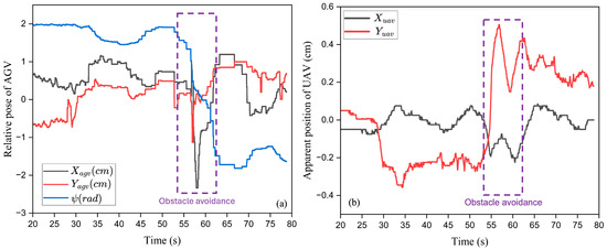
Figure 22.
(a) Variation in apparent pose of AGV in UAV image frame and (b) variation in apparent position of UAV in AGV image frame.
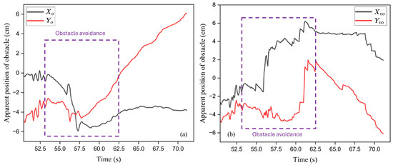
Figure 23.
(a) Apparent position of obstacle in UAV image frame and (b) apparent position of obstacle in AGV virtual plane during obstacle avoidance.
Thus, according to the above discussion, the UAV successfully guides the AGV to avoid obstacles without communicating with it. In [19,21,22], authors performed similar experiments for the obstacle avoidance of an AGV guided by a UAV. However, initially, the UAV reaches the destination to create an obstacle map of the environment and communicates to the AGV. The AGV then navigates towards the UAV using the map [19]. In [21,22], the communication of obstacle information to the AGV is required. A recent work [38] focused on a similar problem, considering multiple obstacles. However, the UAV requires communication with the AGV for sending planned optimal paths. The present method is able to achieve the same goal without the requirement of a map and communication between both agents. A target velocity is given to the UAV instead of a target location in the current work. Hence, the proposed method is useful when an AGV is not communicating with a UAV. However, the method is validated at lower velocities, and only a single obstacle is considered in the FOV of the UAV. And it is also applicable for simple environments. In this work, classical machine vision is implemented for the detection of obstacles and the AGV. However, CNN-based algorithms can be implemented for the same purpose to make the strategy robust for outdoor implementation. Moreover, enhanced filtering techniques for camera sensor data would also make the method effective for outdoor conditions.
The proposed method can also be extended to situations with multiple static/dynamic obstacles, as shown in Figure 24. However, in this case, the UAV must execute real-time path planning to avoid virtual obstacles in its plane of motion. Virtual obstacles are present in the image frame as shown in Figure 24. The UAV conducts path planning in real time to avoid the virtual obstacles. State-of-the-art path planning techniques can be implemented for the same purpose. The role of the AGV is only to track the motion of the UAV to avoid the physical obstacles on the ground plane. The tracking task of the AGV plays an important role in the successful execution of navigation. The proposed method plays a significant role in the safety and rescue missions of the UAV-AGV system where faults may occur. When a sudden fault occurs in the AGV, the UAV can take off from the AGV and can provide navigation guidance.
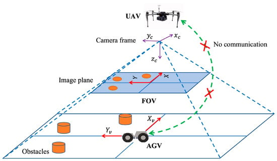
Figure 24.
Multiple static/dynamic obstacles in FOV of UAV.
8. Conclusions
The problem of navigation guidance for an AGV when it is experiencing failure of its sensor and communication modules is considered. An obstacle avoidance method for non-communicating AGVs by tracking the motion of UAVs is proposed and experimentally presented in this work. ArUco markers of two different parameters are placed over the AGV and obstacle for detection by the UAV with its down-facing camera. The AGV is mounted with a sky-facing wide-angle camera to localize the UAV. CNN-based methods are implemented for detecting the drone during its flight. YOLO v8n is custom-trained and deployed in the AGV for the same purpose. A vision-based tracking controller is developed for a non-holonomic AGV to track the motion of the UAV. A vision-based heading control strategy is developed, which ensures the heading of the AGV is always towards the center of the UAV projected on the ground plane. Tracking experiments alone are performed to validate the tracking controller. An obstacle is localized in a virtual plane of the AGV to develop a controller to avoid it. An obstacle avoidance controller is developed and verified with simulations. It is virtually designed for the AGV, and control actions are performed by the UAV. An experimental validation of the proposed obstacle avoidance method is presented. The direction of the velocity of the UAV is along the . axis of the virtual plane of the AGV during obstacle avoidance. It is worth noting that the position of the obstacle with respect to the AGV is not communicated to the AGV during navigation. Hence, the method is significant when the agents are not communicating or are unable to communicate. Both the tracking tasks and obstacle avoidance of the AGV are executed without communication between the agents. This indicates the significance of the method for outdoor missions, especially for safety and rescue missions. In the present work, the method is validated for a single obstacle in the field. Validation considering multiple obstacles in the field will broaden the application scope of the proposed method. This is taken as an extension of the present work. Also, the implementation of learning-based methods for the detection of obstacles and AGVs would make the proposed method robust for outdoor implementation.
Supplementary Materials
Supplementary material can be accessed from the YouTube video links attached below. Non-communicative tracking of a UAV by an AGV: https://youtu.be/c428f-GJScQ?si=HNoZjoSJ-u81pJN7 (accessed on 30 December 2024); UAV-assisted obstacle avoidance of an AGV: https://youtu.be/XMwfPwHovIw?si=4NgqdoXohueFzaav (accessed on 30 December 2024).
Author Contributions
Hardware development, experimentation, and writing initial draft: A.K.S. Supervision and editing: A.S. All authors have read and agreed to the published version of the manuscript.
Funding
This research received no external funding.
Data Availability Statement
Data of the current study are available upon reasonable request to the corresponding author.
Acknowledgments
The authors would like to acknowledge the research colleagues and the Indian Institute of Technology Mandi, India.
Conflicts of Interest
The authors declare no conflicts of interest.
Abbreviations
| UAV | Unmanned Aerial Vehicle/Aerial Vehicle/Drone |
| AGV | Autonomous Ground Vehicle/Unmanned Ground Vehicle/Ground Vehicle |
| UAV-AGV | Unmanned Aerial Vehicle–Autonomous Ground Vehicle |
| GPS | Global Positioning System |
| FOV | Field of View |
| DNNs | Deep Neural Networks |
| CNNs | Convolutional Neural Networks |
| YOLO | You Only Look Once |
| VP | Virtual Plane |
| IMU | Inertial Measurement Unit |
References
- Munasinghe, I.; Perera, A.; Deo, R.C. A Comprehensive Review of UAV-UGV Collaboration: Advancements and Challenges. J. Sens. Actuator Netw. 2024, 13, 81. [Google Scholar] [CrossRef]
- Liu, C.; Zhao, J.; Sun, N. A Review of Collaborative Air-Ground Robots Research. J. Intell. Robot. Syst. 2022, 106, 1–28. [Google Scholar] [CrossRef]
- Ding, Y.; Xin, B.; Chen, J. A Review of Recent Advances in Coordination Between Unmanned Aerial and Ground Vehicles. Unmanned Syst. 2021, 9, 97–117. [Google Scholar] [CrossRef]
- Sivarathri, A.K.; Shukla, A.; Gupta, A. Kinematic modes of vision-based heterogeneous UAV-AGV system. Array 2023, 17, 100269. [Google Scholar] [CrossRef]
- Yang, T.; Ren, Q.; Zhang, F.; Xie, B.; Ren, H.; Li, J.; Zhang, Y. Hybrid Camera Array-Based UAV Auto-Landing on Moving UGV in GPS-Denied Environment. Remote Sens. 2018, 10, 1829. [Google Scholar] [CrossRef]
- Keipour, A.; Pereira, G.A.S.; Bonatti, R.; Garg, R.; Rastogi, P.; Dubey, G.; Scherer, S. Visual servoing approach for autonomous UAV landing on a moving vehicle. arXiv 2021, arXiv:2104.01272. [Google Scholar] [CrossRef]
- Baca, T.; Stepan, P.; Spurny, V.; Hert, D.; Penicka, R.; Saska, M.; Thomas, J.; Loianno, G.; Kumar, V. Autonomous landing on a moving vehicle with an unmanned aerial vehicle. J. Field Robot. 2019, 36, 874–891. [Google Scholar] [CrossRef]
- Respall, V.M.; Sellami, S.; Afanasyev, I. Implementation of autonomous visual detection, tracking and landing for AR. Drone 2.0 quadcopter. In Proceedings of the 2019 IEEE 12th International Conference on Developments in eSystems Engineering (DeSE), Kazan, Russia, 7–10 October 2019. [Google Scholar]
- Xin, L.; Tang, Z.; Gai, W.; Liu, H. Vision-Based Autonomous Landing for the UAV: A Review. Aerospace 2022, 9, 634. [Google Scholar] [CrossRef]
- Hoang, T.; Bayasgalan, E.; Wang, Z.; Tsechpenakis, G.; Panagou, D. Vision-based target tracking and autonomous landing of a quadrotor on a ground vehicle. In Proceedings of the 2017 American Control Conference (ACC), Seattle, WA, USA, 24–26 May 2017; pp. 5580–5585. [Google Scholar]
- Sudevan, V.; Shukla, A.; Karki, H. Vision based autonomous landing of an Unmanned Aerial Vehicle on a stationary target. In Proceedings of the 2017 17th International Conference on Control, Automation and Systems (ICCAS), Ramada Plaza, Jeju, Republic of Korea, 18–21 October 2017; pp. 362–367. [Google Scholar]
- Cantieri, A.; Ferraz, M.; Szekir, G.; Antônio Teixeira, M.; Lima, J.; Schneider Oliveira, A.; Aurélio Wehrmeister, M. Cooperative UAV–UGV Autonomous Power Pylon Inspection: An Investigation of Cooperative Outdoor Vehicle Positioning Architecture. Sensors 2020, 20, 6384. [Google Scholar] [CrossRef]
- Asadi, K.; Suresh, A.K.; Ender, A.; Gotad, S.; Maniyar, S.; Anand, S.; Noghabaei, M.; Han, K.; Lobaton, E.; Wu, T. An integrated UGV-UAV system for construction site data collection. Autom. Constr. 2020, 112, 103068. [Google Scholar] [CrossRef]
- Elmakis, O.; Shaked, T.; Degani, A. Vision-Based UAV-UGV Collaboration for Autonomous Construction Site Preparation. IEEE Access 2022, 10, 51209–51220. [Google Scholar] [CrossRef]
- Qin, H.; Meng, Z.; Meng, W.; Chen, X.; Sun, H.; Lin, F.; Ang, M.H. Autonomous exploration and mapping system using heterogeneous UAVs and UGVs in GPS-denied environments. IEEE Trans. Veh. Technol. 2019, 68, 1339–1350. [Google Scholar] [CrossRef]
- Tagarakis, A.C.; Filippou, E.; Kalaitzidis, D.; Benos, L.; Busato, P.; Bochtis, D. Proposing UGV and UAV Systems for 3D Mapping of Orchard Environments. Sensors 2022, 22, 1571. [Google Scholar] [CrossRef] [PubMed]
- Sivarathri, A.K.; Shukla, A.; Gupta, A. Waypoint Navigation in the Image Plane for Autonomous Navigation of UAV in Vision-Based UAV-AGV System. In Proceedings of the 2024 20th IEEE/ASME International Conference on Mechatronic and Embedded Systems and Applications (MESA), Genova, Italy, 2–4 September 2024. [Google Scholar]
- Wang, C.; Wang, J.; Wei, C.; Zhu, Y.; Yin, D.; Li, J. Vision-Based Deep Reinforcement Learning of UAV-UGV Collaborative Landing Policy Using Automatic Curriculum. Drones 2023, 7, 676. [Google Scholar] [CrossRef]
- Peterson, J.; Chaudhry, H.; Abdelatty, K.; Bird, J.; Kochersberger, K. Online Aerial Terrain Mapping for Ground Robot Navigation. Sensors 2018, 18, 630. [Google Scholar] [CrossRef]
- Martínez, J.L.; Morales, J.; Sánchez, M.; Morán, M.; Reina, A.J.; Fernández-Lozano, J.J. Reactive navigation on natural environments by continuous classification of ground traversability. Sensors 2020, 20, 6423. [Google Scholar] [CrossRef] [PubMed]
- Kandath, H.; Bera, T.; Bardhan, R.; Sundaram, S. Autonomous navigation and sensorless obstacle avoidance for UGV with environment information from UAV. In Proceedings of the 2018 Second IEEE International Conference on Robotic Computing (IRC), Laguna Hills, CA, USA, 31 January–2 February 2018. [Google Scholar]
- Garzón, M.; Valente, J.; Zapata, D.; Barrientos, A. An aerial–ground robotic system for navigation and obstacle mapping in large outdoor areas. Sensors 2013, 13, 1247–1267. [Google Scholar] [CrossRef]
- Santos, M.F.; Castillo, P.; Victorino, A.C. Aerial Vision Based Guidance and control for Perception-Less Ground Vehicle. In Proceedings of the 2024 European Control Conference (ECC), Stockholm, Sweden, 25–28 June 2024; pp. 2780–2785. [Google Scholar]
- Bacheti, V.P.; Brandao, A.S.; Sarcinelli-Filho, M. A Path-Following Controller for a UAV-UGV Formation Performing the Final Step of Last-Mile-Delivery. IEEE Access 2021, 9, 142218–142231. [Google Scholar] [CrossRef]
- Wu, Q.; Qi, J.; Wu, C.; Wang, M. Design of UGV Trajectory Tracking Controller in UGV-UAV Cooperation. In Proceedings of the 2020 39th Chinese Control Conference (CCC), Shenyang, China, 27–29 July 2020; pp. 3689–3694. [Google Scholar]
- Ulun, S.; Unel, M. Coordinated motion of UGVs and a UAV. In Proceedings of the IEEE IECON 2013-39th Annual Conference of the IEEE Industrial Electronics Society, Vienna, Austria, 10–13 November 2013. [Google Scholar]
- Harik, E.H.C.; Guerin, F.; Guinand, F.; Brethe, J.-F.; Pelvillain, H. UAV-UGV cooperation for objects transportation in an industrial area. In Proceedings of the 2015 IEEE International Conference on Industrial Technology (ICIT), Seville, Spain, 17–19 March 2015; pp. 547–552. [Google Scholar]
- Wei, Y.; Qiu, H.; Liu, Y.; Du, J. Unmanned aerial vehicle (UAV)-assisted unmanned ground vehicle (UGV) systems design, implementation and optimization. In Proceedings of the 2017 3rd IEEE International Conference on Computer and Communications (ICCC), Chengdu, China, 13–16 December 2017. [Google Scholar]
- Sivarathri, A.K.; Shukla, A.; Kumar, P. Autonomous Vision-based Tracking of UAV by a Flexible AGV. In Proceedings of the 2024 20th IEEE/ASME International Conference on Mechatronic and Embedded Systems and Applications (MESA), Genova, Italy, 2–4 September 2024. [Google Scholar]
- Cantelli, L.; Mangiameli, M.; Melita, C.D.; Muscato, G. UAV/UGV cooperation for surveying operations in humanitarian demining. In Proceedings of the 2013 IEEE International Symposium on Safety, Security, and Rescue Robotics (SSRR), Linköping, Sweden, 21–26 October 2013; pp. 1–6. [Google Scholar] [CrossRef]
- Jocher, G.; Qiu, J.; Chaurasia, A. Ultralytics YOLO (Version 8.0.0) [Computer Software]. 2023. Available online: https://github.com/ultralytics/ultralytics (accessed on 15 April 2024).
- Chen, Y.; Wu, Y.; Zhang, Z.; Miao, Z.; Zhong, H.; Zhang, H.; Wang, Y. Image-Based Visual Servoing of Unmanned Aerial Manipulators for Tracking and Grasping a Moving Target. IEEE Trans. Ind. Informatics 2022, 19, 8889–8899. [Google Scholar] [CrossRef]
- Feng, K.; Li, W.; Ge, S.; Pan, F. Packages delivery based on marker detection for UAVs. In Proceedings of the 2020 Chinese Control And Decision Conference (CCDC), Hefei, China, 22–24 August 2020; pp. 2094–2099. [Google Scholar]
- Kamath, A.K.; Tripathi, V.K.; Behera, L. Vision-based autonomous control schemes for quadrotor unmanned aerial vehicle. In Unmanned Robotic Systems and Applications; IntechOpen Limited: London, UK, 2019; Available online: https://www.intechopen.com/chapters/67003 (accessed on 15 April 2024).
- Sivarathri, A.K.; Shukla, A.; Gupta, A.; Kumar, A. Trajectory Tracking in the Image Frame for Autonomous Navigation of UAV in UAV-AGV Multi-Agent System. In Proceedings of the ASME International Mechanical Engineering Congress and Exposition, Columbus, OH, USA, 30 October–3 November 2022; Volume 86656. [Google Scholar]
- Singh, P.; Agrawal, P.; Karki, H.; Shukla, A.; Verma, N.K.; Behera, L. Vision-Based Guidance and Switching-Based Sliding Mode Controller for a Mobile Robot in the Cyber Physical Framework. IEEE Trans. Ind. Inform. 2018, 15, 1985–1997. [Google Scholar] [CrossRef]
- Liu, J.; Wang, X. Advanced Sliding Mode Control for Mechanical Systems; Springer: Berlin, Germany, 2012. [Google Scholar]
- Huang, J.; Chen, J.; Zhang, Z.; Chen, Y.; Lin, D. On Real-time Cooperative Trajectory Planning of Aerial-ground Systems. J. Intell. Robot. Syst. 2024, 110, 20. [Google Scholar] [CrossRef]
Disclaimer/Publisher’s Note: The statements, opinions and data contained in all publications are solely those of the individual author(s) and contributor(s) and not of MDPI and/or the editor(s). MDPI and/or the editor(s) disclaim responsibility for any injury to people or property resulting from any ideas, methods, instructions or products referred to in the content. |
© 2025 by the authors. Licensee MDPI, Basel, Switzerland. This article is an open access article distributed under the terms and conditions of the Creative Commons Attribution (CC BY) license (https://creativecommons.org/licenses/by/4.0/).

