4.1. Analysis of Open-Water Performance of Submerged Jet Propeller and Conventional Propeller
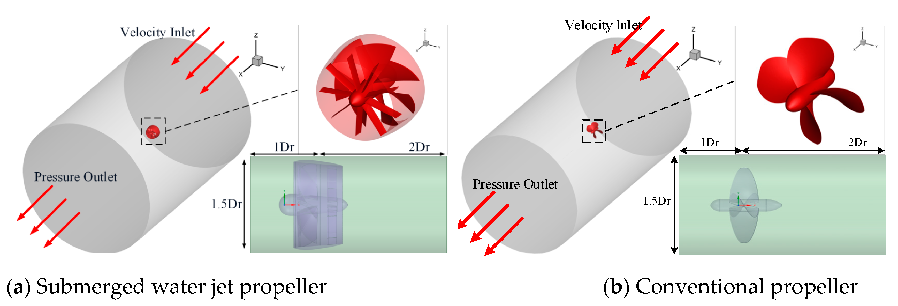
Firstly, the open-water performance of the submerged water jet propeller and the conventional propeller was calculated and compared [
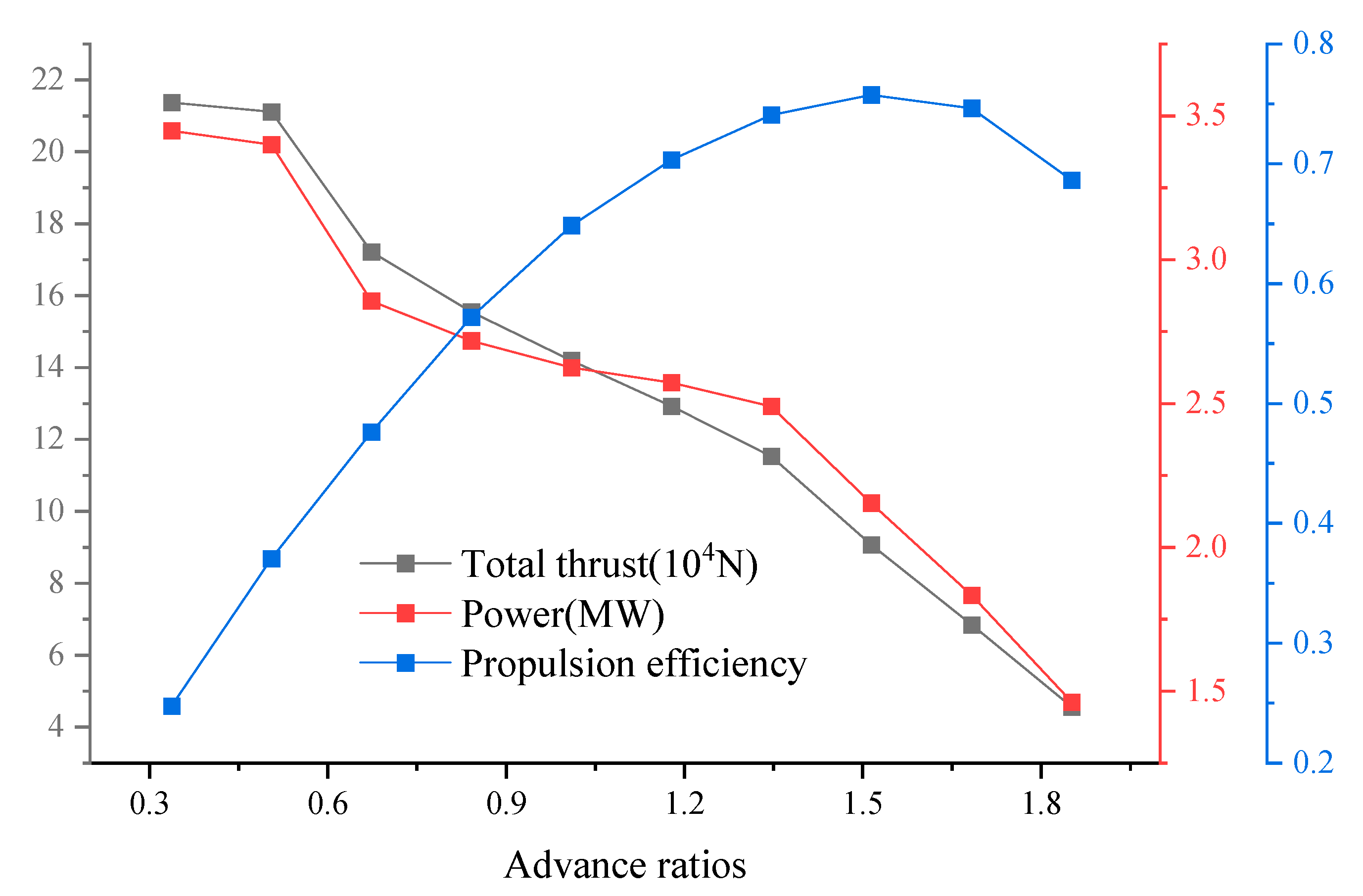
26]. The performance curve of the full advance ratios of the submerged water jet propeller was calculated, and the calculation results are shown in
Table 5 and
Figure 9.
Since the thrust and torque of the conventional propeller are very large at low speeds, there is no reference for comparison with the performance of the submerged water jet propeller, so only the designed working condition of the propeller is calculated, that is, an inflow velocity is 18 m/s. The hydrodynamic performance of the propeller under this working condition is shown in
Table 6.
From the above table and curve analysis, it can be seen that the peak open-water efficiency of the submerged water jet propeller is 6.67% higher than that of the conventional propeller. This performance advantage is mainly attributed to the special layout of the submerged water jet propeller, where the stator is located downstream of the rotor. This layout effectively recovers the rotational kinetic energy in the rotor wake stream, significantly reducing energy dissipation. Through this energy recovery mechanism, the thruster achieves higher propulsive efficiency over a wide range of advance ratios, especially at high speeds. This characteristic suggests that the submerged water jet propeller has significant efficiency advantages under high speed conditions and can provide more efficient power support for ships.
4.2. Cavitation Performance Analysis of Submerged Water Jet Propeller and Conventional Propeller
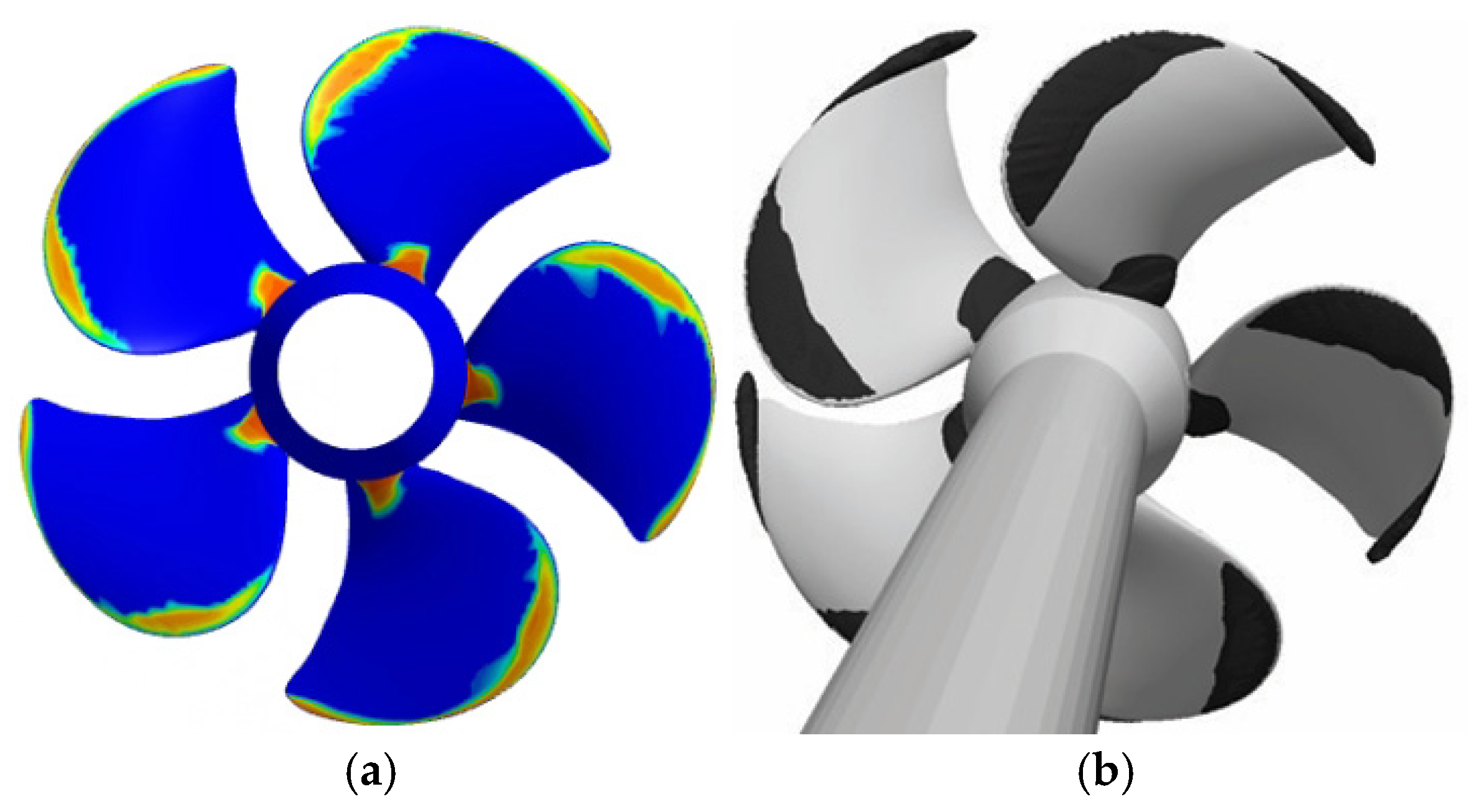
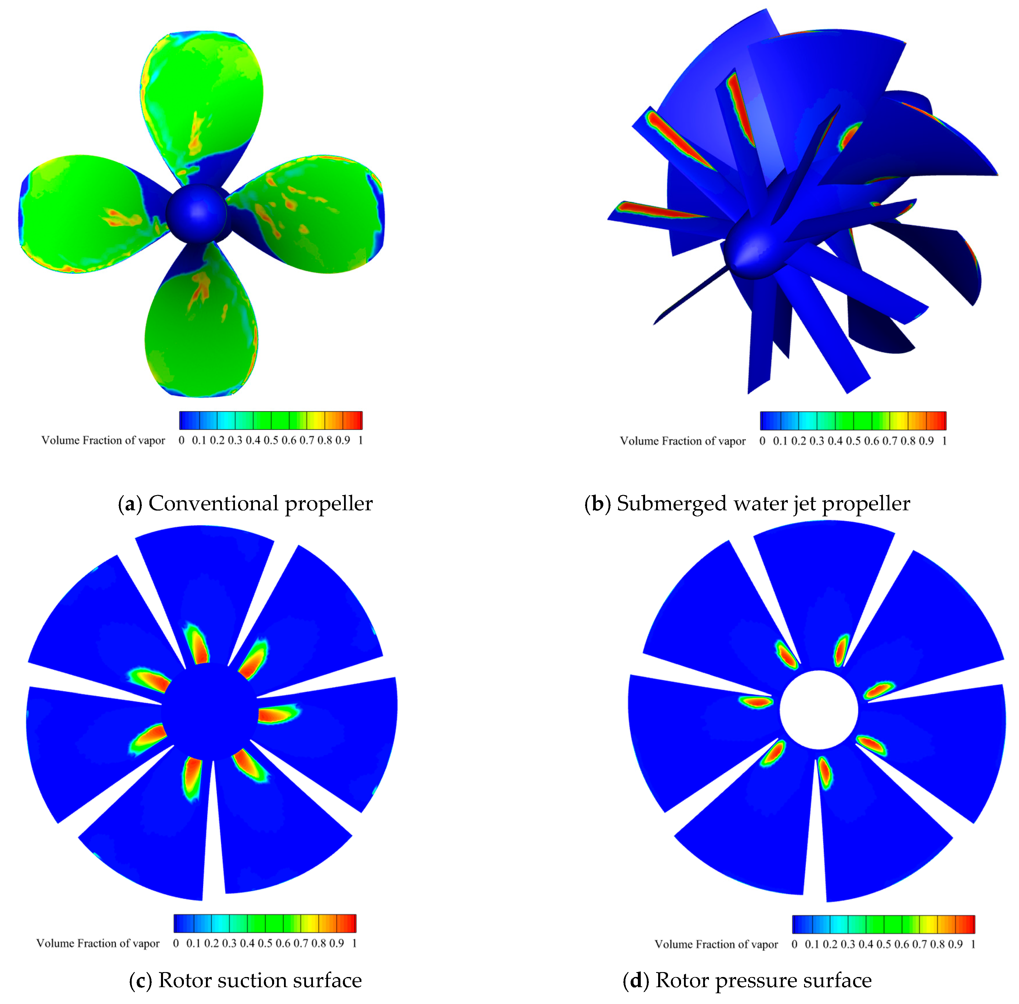
The cavitation performance of the submerged water jet propeller and the conventional propeller is analyzed below. The cavitation model adopts the Schnerr–Sauer cavitation model. Since the working conditions studied in this paper are actual ship operating conditions, there is no fixed cavitation number, and the environmental pressure of the propeller can only be specified as the pressure at 3 m underwater. The saturated vapor pressure is 3170 Pa. The cavitation contour and calculation results for the conventional propeller and the submerged water jet propeller are shown in
Figure 10 and
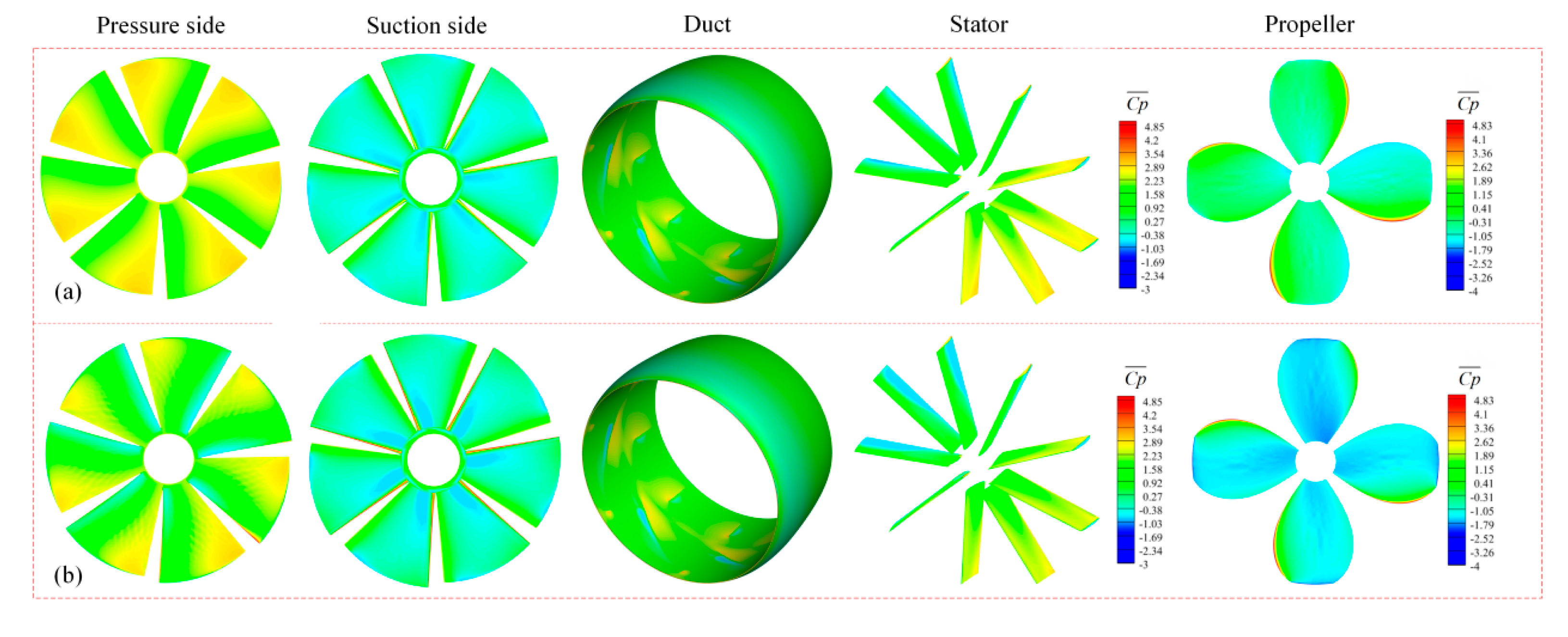
Figure 11 and
Table 7.
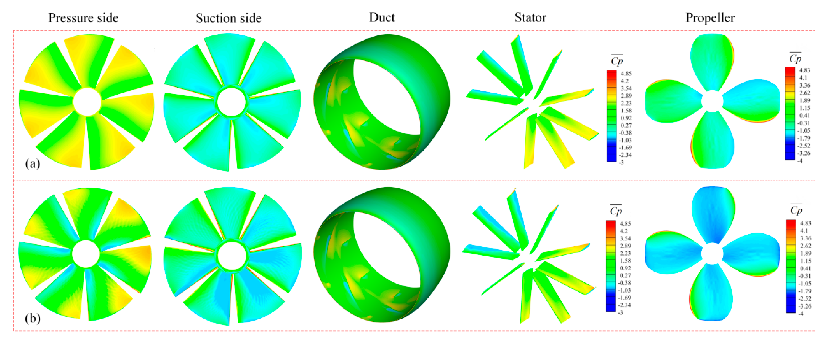
From the pressure coefficient contours, it can be seen that after the fluid begins to enter the rotor domain, the fluid in the rotor domain is accelerated by the rotating acceleration of the rotor. The pressure near the blade tip of the rotor pressure surface is large, which promotes the development of the fluid. The highest-pressure point of the rotor appears at the leading edge of the pressure surface, while the pressure level of the rotor suction surface is low. In particular, there is a relatively obvious low-pressure area near the tip of the leading edge, which is mainly caused by the tip leakage vortex generated by the clearance flow. In addition, there are also obvious low-pressure areas near the rotor hub and in front of the rotor at the tail of the stator. As can be seen from the cavitation contour, these areas are also prone to the cavitation phenomenon. The pressure distribution on the outer wall of the duct is more uniform, and there is a more obvious pressure gradient at the front of the duct, and the pressure at the front of the duct is larger. This is mainly due to the impact of incoming flow. It can also be seen from the contour that the pressure distribution law of the pressure surface and suction surface of the stator blade is basically the same as that of the rotor blade. This is mainly because the distance between the rotor and the stator is small, and the flow field in the stator domain is greatly affected by the flow field in the rotor domain, and the pressure characteristics of the flow field in the rotor domain are basically maintained. However, because the stator has an obvious reverse velocity gradient, and because the stator can convert a part of the tangential velocity into axial velocity by performing work on the fluid, thus generating a small amount of extra thrust, the change in the pressure distribution of the stator blade is not as obvious as that of the rotor blade.
From the analysis of the cavitation contour, it can be seen that the tip of the propeller blade has a large linear velocity, and the local pressure can easily fall below the saturated vapor pressure, which triggers a significant cavitation phenomenon. The cavitation area is widely distributed in the whole rotor surface, showing different degrees of flaky cavitation and cloudy cavitation. At this time, the rotational speed of the propeller is 770 RPM, and the advance ratio is 1.08, which is close to an advance ratio of 1.258, corresponding to the highest efficiency point of the real-scale model. According to the performance characteristics of the propeller, the optimal efficiency point is usually taken to be about 70% of the advance ratio corresponding to the highest efficiency point, and after exceeding this value, the propeller’s thrust and efficiency will be drastically reduced. Therefore, under this high-risk condition, even if 18 m/s and 770 RPM are selected as the optimal efficiency point of the propeller, its open-water efficiency is only 69.08%, and the efficiency is further reduced to 63.1% after cavitation.
In contrast, the cavitation area of the submerged water jet propeller is mainly concentrated in the rotor suction surface near the leading edge and the blade top area. At the same time, due to the influence of the inlet angle, local cavitation also occurs in the rotor pressure surface near the hub. The stator can effectively rectify the rotational energy in the rotor wake and convert circumferential motion into axial motion. This improves the contraction phenomenon of the hub wake, avoids the unnecessary consumption of energy here, eliminates the low-pressure area in the wake, and significantly reduces the cavitation effect. This design enables the submerged water jet propeller to maintain high propulsive efficiency under cavitation conditions, especially at high speeds, where the performance advantage is more significant.
In summary, the performance of the submerged water jet propeller at high speeds is significantly better than that of the conventional high-efficiency propeller, especially in terms of its ability to maintain efficiency under cavitation conditions, which is a significant advantage for engineering applications.
4.3. Performance Analysis of Submerged Water Jet Propeller and Conventional High-Efficiency Propeller Considering the Influence of Vehicle Body Wake
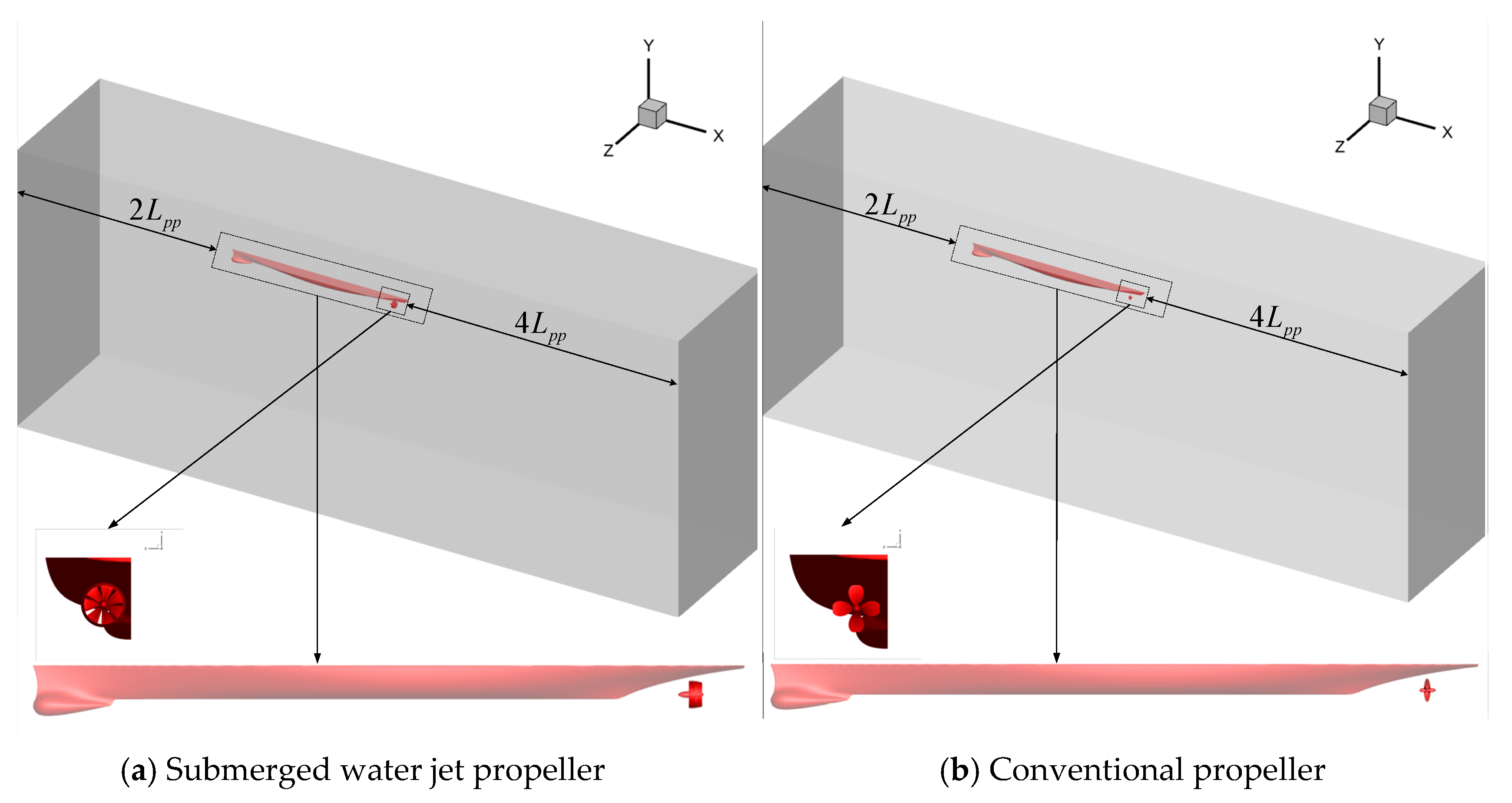
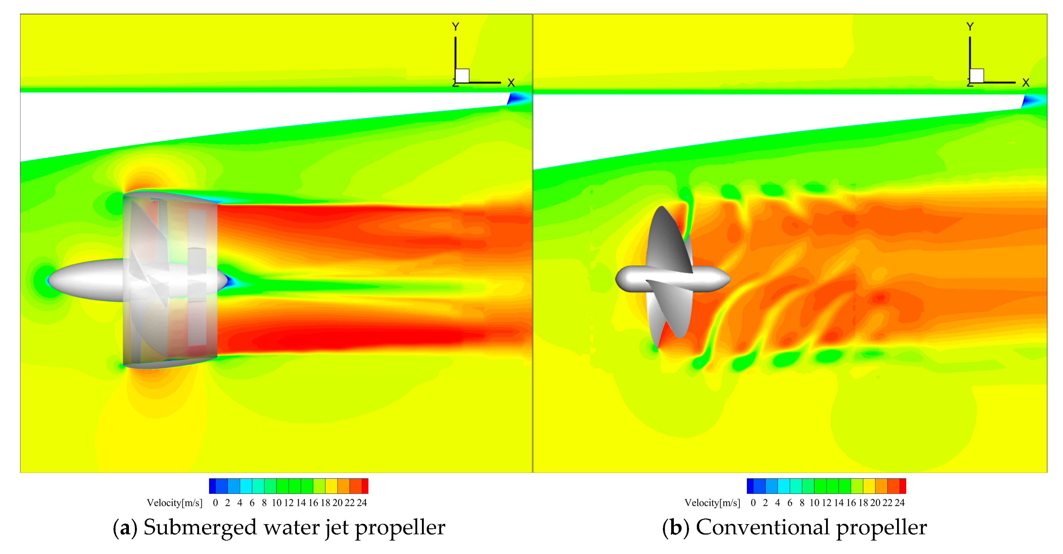
In the previous section, the open-water performance and cavitation performance of the submerged water jet propeller and the conventional high-efficiency propeller were calculated, and it was found that the performance of the submerged water jet propeller was significantly better than that of the conventional propeller. In this section, the performance of the submerged water jet propeller and the conventional high-efficiency propeller is calculated and compared while taking the influence of the vehicle body’s wake into consideration. The calculation results are shown in
Figure 12 below.
As can be seen from the velocity contour of the submerged water jet propeller, the velocity of its external flow field basically presents a linear distribution, and the flow field structure is relatively clear and simple, belonging to the outflow problem in a large space. The flow field in the duct has a direct effect on the outflow field, and it can be seen from the contour that the wake acceleration brought by the duct is obvious. The value of wake axial velocity is much larger and more uniform, resulting in an obvious propulsion effect.
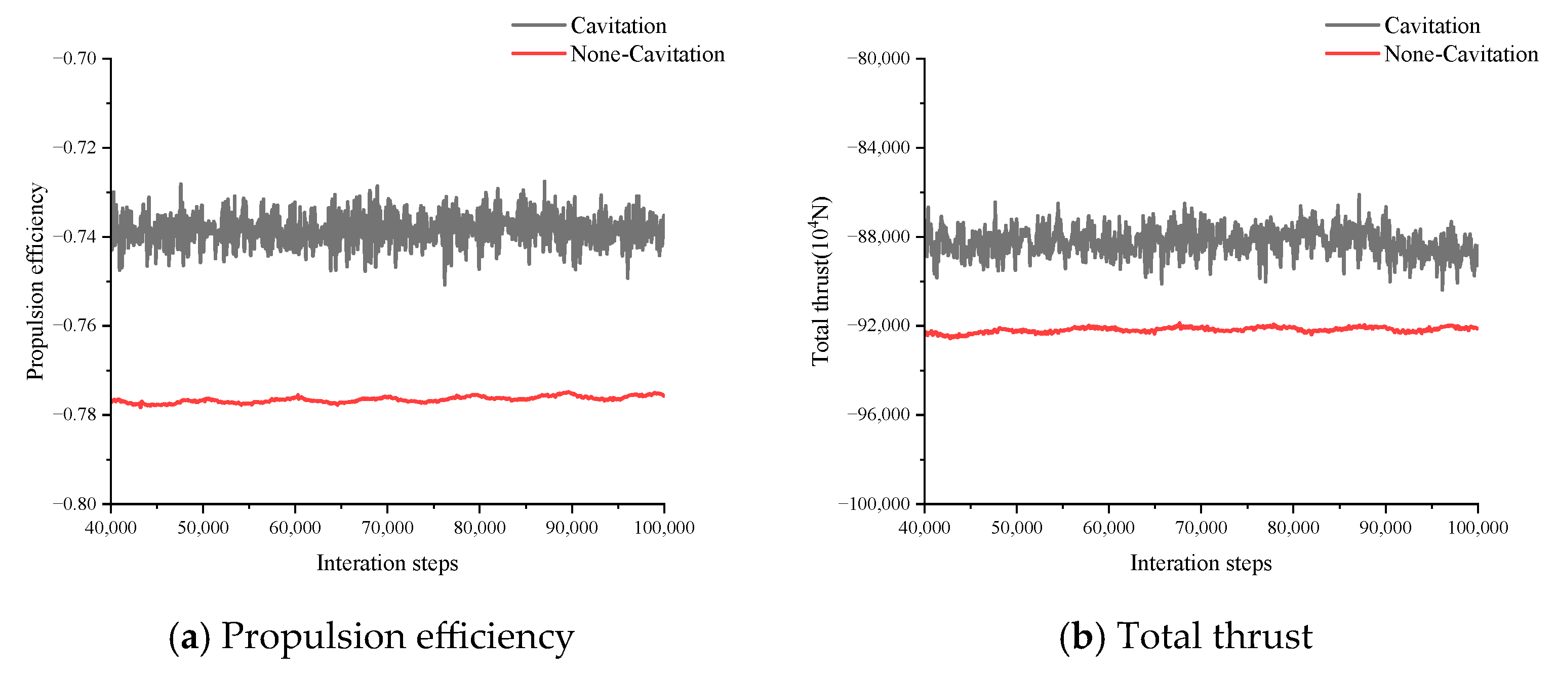
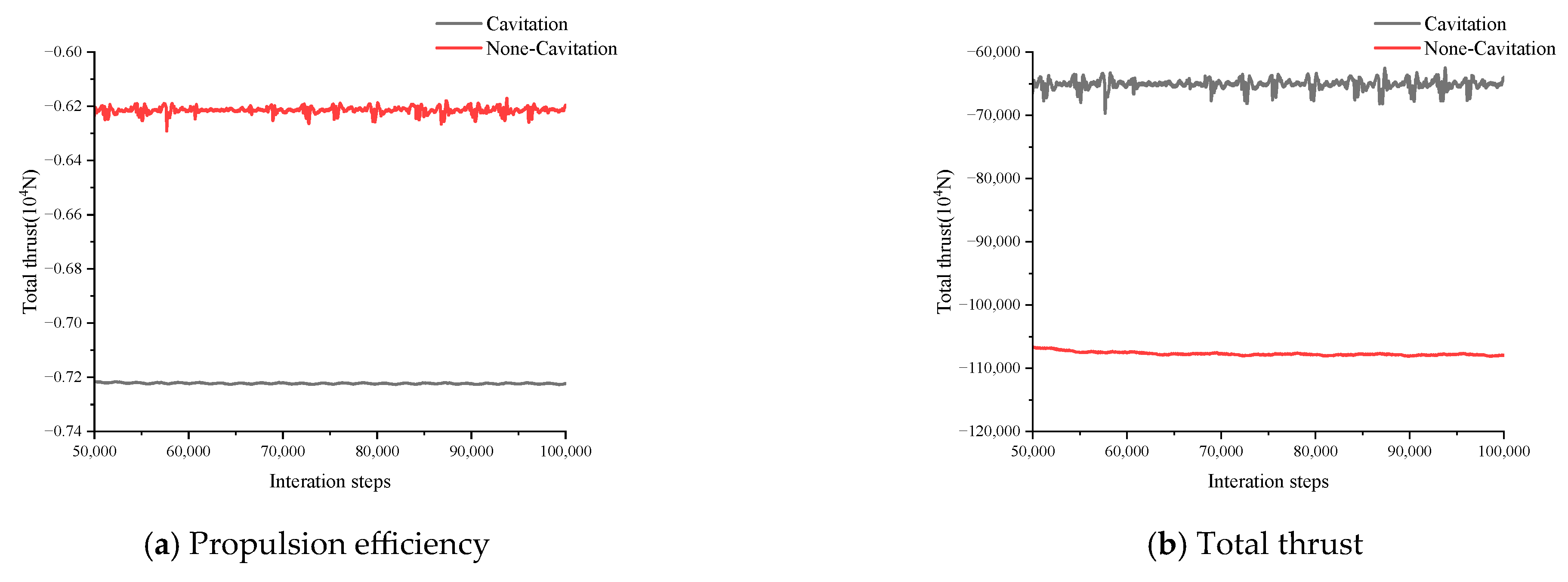
It can be seen from the curves in
Figure 13 and
Figure 14, considering the influence of the vehicle body’s wake, the total thrust of the propeller before cavitation is about 10.8 × 10
4 N, and the total thrust after cavitation is about 6.5 × 10
4 N under the condition that the incoming flow velocity is 18 m/s. The propulsion efficiency of the propeller before cavitation is about 72.3%, and after cavitation, it is about 62%. The total thrust of the submerged water jet propeller before cavitation is about 9.22 × 10
4 N, and after cavitation, it is about 8.7 × 10
4 N. The propulsive efficiency of the submerged water jet propeller is about 77.5% before cavitation and 74.27% after cavitation.
From the above curves, it can also be found that the total thrust and propulsive efficiency curves before cavitation are relatively smooth, while those after cavitation show fluctuations of different magnitudes. This is because when the cavitation phenomenon occurs, the local pressure on the surface of the blade decreases below the saturated vapor pressure, forming bubbles. The existence of these bubbles changes the pressure distribution on the blade surface. Moreover, the collapse of these bubbles will produce local high-pressure shock waves and micro-jets, strip the surface of the blade, and at the same time cause intense pulsating pressure. This pulsating pressure not only reduces the thrust of the blade but also leads to an increase in the vibration and noise of the blade. In addition, the high-pressure shock wave generated in the process of vacuole collapse will make the pressure distribution on the blade surface more complicated, which further affects the stability of the thrust and propulsion efficiency. And the cavitation phenomenon will lead to a constant change in the cavitation region on the blade surface, which may expand or shrink rapidly. This instability makes it difficult to keep the pressure distribution and thrust output of the blade stable, leading to drastic fluctuations in thrust and efficiency.
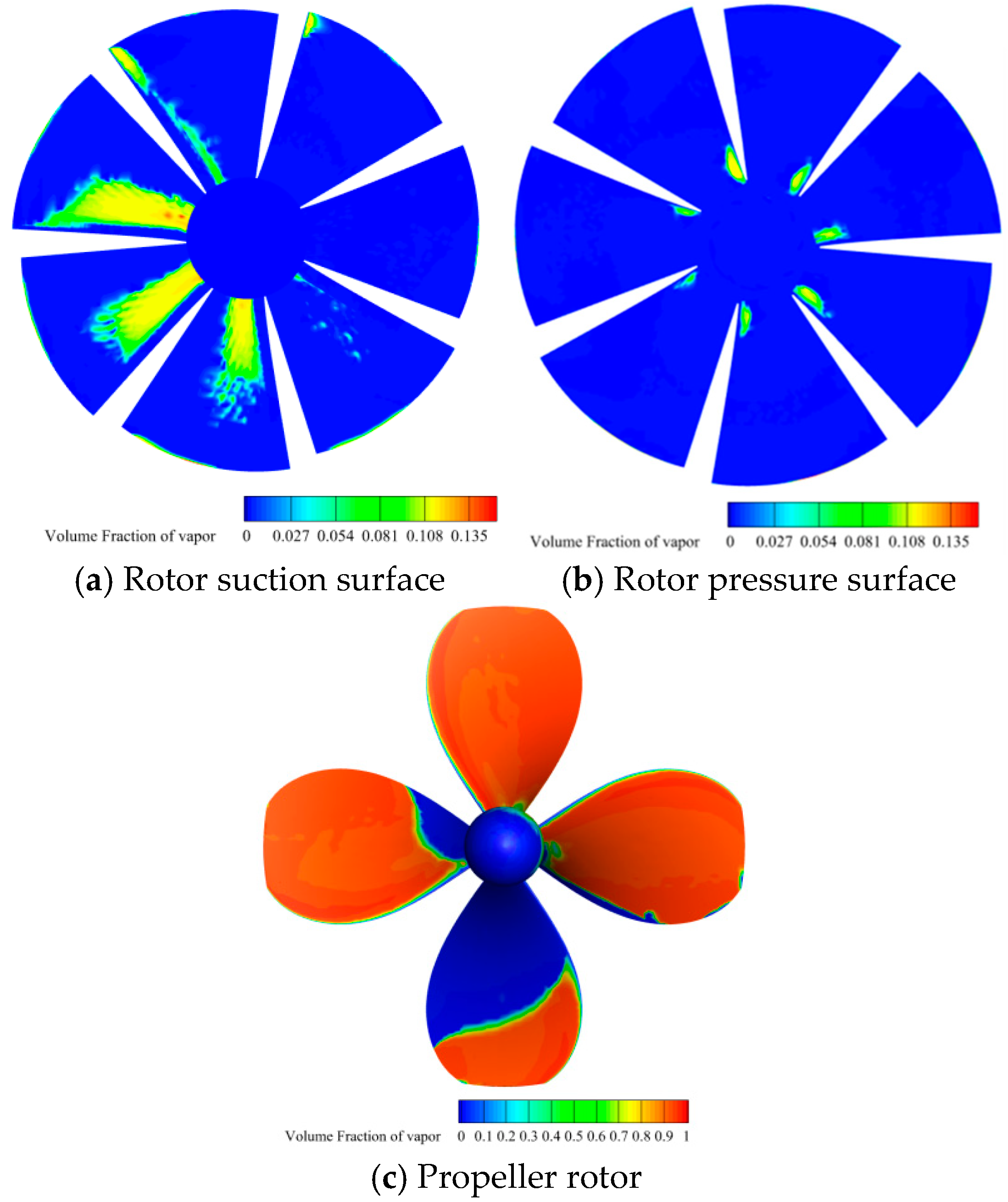
The three contours in
Figure 15 are are the cavitation contours of the conventional propeller and the submerged water jet propeller considering the influence of the vehicle body’s wake. It can be seen that under the condition of an inflow velocity of 18 m/s, a large cavitation area occurs on the whole rotor surface of the propeller, and the hydrodynamic performance also deteriorates significantly. For the submerged water jet propeller, cavitation mainly occurs at the leading edge of the rotor suction surface, and a small cavitation area also occurs at the pressure surface near the leading edge and the hub due to the influence of flow angle.
As can be seen from the pressure coefficient contours in
Figure 16, considering the role of the vehicle body’s wake, the pressure distribution of each component of the submerged water jet propeller and conventional propeller is basically the same as that under the open-water condition described in the previous section. However, the vehicle body wake causes the low-pressure area on the rotor and stator of the submerged water jet propeller and on the rotor of the conventional propeller, which is prone to cavitation, to gradually expand. That is, the vehicle body’s wake will aggravate the cavitation of the submerged water jet propeller and conventional propeller.
In order to make a more convenient comparison, the calculation results of the conventional propeller and the submerged water jet propeller in this section are summarized under different working conditions, and the results are shown in
Table 8.
It can be seen that the effect of vehicle body wake flow causes an increase in the total thrust of the submerged water jet propeller and the conventional propeller, resulting in a further increase in propulsive efficiency. The reason is that the flow field formed in the wake of the ship while sailing is non-uniform, and its velocity distribution and pressure distribution are different from those of the surrounding flow field. The presence of the wake flow increases the inlet velocity of the thruster, especially near the thruster disk, and the increase in flow velocity helps to increase the thrust and efficiency of the thruster. Moreover, the wake contains part of the energy generated by the ship, which can be recovered and converted into thrust when the thruster works in the wake. This energy recovery mechanism makes the efficiency of the thruster under actual working conditions higher than that under open-water conditions alone. However, the vehicle body’s wake also further exacerbates the total thrust and propulsive efficiency losses of the submerged water jet propeller and conventional propeller after cavitation due to the fact that the vehicle body’s wake is non-uniform, with velocity and pressure distributions that differ significantly from those of a uniform flow field. This non-uniformity alters the inlet flow conditions of the propeller, causing the pressure in localized regions to decrease more rapidly, thus exacerbating cavitation. Under low-advance-ratio conditions, the low-velocity region in the wake flow may cause the local pressure to decrease to the vaporization pressure, which triggers cavitation in advance. Moreover, the presence of the vehicle body’s wake flow will expand the cavitation region; especially, the cavitation initialization in the region at the back of the blade is advanced, and the cavitation range is increased significantly. The expansion of the cavitation region leads directly to a reduction in the effective working area of the propeller, which in turn reduces the thrust output.
As can be seen from the data in the table, the submerged water jet propeller significantly outperforms the conventional high-efficiency propeller in terms of its hydrodynamic performance and cavitation characteristics, both in open-water conditions and in conditions that take into account the vehicle body wake effects. The propulsive efficiency of the submerged water jet propeller is at least 5% and up to 12.27% higher than that of the conventional high-efficiency propeller in all conditions. This indicates that under high-speed conditions near the water surface, the submerged water jet propeller can effectively improve the propulsion efficiency and reduce the risk of cavitation by its unique energy recovery mechanism and its ability to inhibit the cavitation phenomenon, which makes it an ideal choice for the propulsion system of high-speed ships.
