Article

Research on Task Allocation Method for Dual-Robot Stereoscopic Stone Carving Under Stiffness Constraints

1
Institute of Manufacturing Engineering, Huaqiao University, Xiamen 361021, China
2
Nan’an Institute of Intelligent Manufacturing, Huaqiao University, Quanzhou 362342, China
*
Author to whom correspondence should be addressed.
Machines 2025, 13(12), 1097; https://doi.org/10.3390/machines13121097
Submission received: 11 October 2025 / Revised: 19 November 2025 / Accepted: 24 November 2025 / Published: 27 November 2025
(This article belongs to the Section Robotics, Mechatronics and Intelligent Machines)

Abstract

Multi-robot systems, owing to their parallel operation and cooperative capabilities, have become an important means of improving the efficiency of complex workpiece machining. However, task allocation methods directly determine the overall system performance, which is particularly critical in scenarios with high curvature and stringent stiffness requirements. This study focuses on a Dual-Robot Carving System (DRCS) and proposes a task allocation method that incorporates stiffness performance constraints, using stereoscopic stone carving as a representative application. First, a workstation optimization model is developed based on the average normal stiffness as the evaluation metric, enabling the selection and allocation of high-complexity tasks. This approach not only ensures machining stiffness but also effectively decouples the task allocation problem. Subsequently, two allocation strategies are designed for low-complexity tasks: one based on machinability and the other on machining time balancing. Comparative simulations and physical experiments are conducted to evaluate the efficiency differences between the proposed methods and the single-robot machining mode. The results show that the machining time balancing strategy improves efficiency by 14.33% compared with the machinability-based strategy, and by 84.78% compared with the single-robot mode. These findings demonstrate the effectiveness of the proposed method in enhancing dual-robot collaborative efficiency and provide a novel modeling perspective and technical support for multi-robot task allocation under stiffness constraints in complex workpiece machining.

Graphical Abstract

1. Introduction

In high-quality automated machining of complex workpieces, industrial robot systems have become indispensable equipment in the field of intelligent manufacturing, owing to their superior flexibility, accessibility, and high repeatability [1,2,3]. Among them, Multi-Robot Systems (MRSs) demonstrate remarkable advantages in improving task execution efficiency and the accessibility of complex tool paths through their capabilities for parallel operation and cooperative manipulation [4,5,6]. However, simply increasing the number of robots does not guarantee performance improvement; instead, it may lead to behavioral conflicts and spatial interference among robots, thereby reducing overall system efficiency and preventing the full realization of the potential advantages of MRSs [7].
Against this background, the task allocation problem has emerged as a central issue, since it is a key factor influencing the performance of multi-robot systems [8]. An MRS can be regarded as a group of robots working toward a common goal, and its collaborative efficiency largely depends on how tasks are reasonably partitioned and scheduled among individual units. Research on task allocation and path planning has evolved continuously under different MRS configurations, gradually forming a systematic body of study. Existing work can generally be categorized into three groups according to the relative motion relationships between robots and workpieces, as illustrated in Figure 1, and different methodological frameworks have been developed with varying emphases for different manufacturing scenarios.
(a) Robots fixed–Workpiece fixed: In this category of systems, both the robot base and the workpiece remain fixed, with no involvement of external axes or part-transfer mechanisms. Research in this paradigm typically centers on compressing the machining time or cycle time, formulating task allocation as a combinatorial optimization problem aimed at minimizing overall processing duration. Within this framework, Spensieri et al. [9] modeled task allocation as a multiple Generalized Traveling Salesman Problem (GTSP) to achieve time-balanced load distribution. Building on this nominal assignment, they further reduced waiting time and idle travel through collision-free routing and coordinated velocity planning, achieving a significant reduction in cycle time in a case study involving four industrial robots performing thirty-two welding operations. Tereshchuk et al. [10], considering geometric and operational constraints, first generated a nominal, collision-free and time-balanced schedule with the objective of minimizing makespan. They then applied an auction-based reallocation mechanism to rebalance workload and optimize insertions under perturbations, demonstrating millisecond-level responsiveness and stable cycle-time compression. Behrens et al. [11] proposed a constraint-programming-based method for simultaneous task allocation and motion scheduling, in which ordered-visit constraints were used to unify temporal, spatial, and precedence relationships among tasks. By coupling task-level models with time-scalable motion sequences defined on a road-map graph via connection variables, the method enabled collision-free coordination and produced executable plans for dual-arm assembly/operation within seconds to minutes. Wu Renjie et al. [12], using curvature cloud maps to segment blade surfaces and estimate the machining time of each region, adopted a greedy algorithm to allocate tasks. Under reachability constraints, the method achieved load balancing and minimized total machining time. Jia et al. [13] employed two heterogeneous six-axis robots for rebar binding and introduced a hybrid assignment strategy combining integer programming with an auction mechanism. A dual-layer planning scheme—global task planning via a double ant-colony algorithm and local path planning via an improved RRT—yielded better workload balance and higher efficiency than K-means-based clustering and standalone auction methods. Li et al. [14], addressing multi-robot WAAM, developed a “top-k%” path-allocation strategy integrated with collision-free scheduling. Experiments showed that this method improved load balancing and shortened processing time.
(b) Robots mobile–Workpiece fixed: In this category of systems, the robot base can be translated or repositioned via external axes such as linear tracks or gantry structures, while the workpiece remains stationary. The overarching objective continues to be the compression of machining or cycle time and the enhancement of execution efficiency. To this end, Liu et al. [15] proposed an integrated “region partitioning+hybrid genetic algorithm” strategy for span-constrained gantry welding operations: large workpieces are first partitioned according to reachability to shrink the search space and reduce waiting time, and then a path-driven crossover operator combined with neighborhood local search is used to jointly optimize task allocation and sequencing, yielding collision-free and efficient cooperative schedules. In three groups of benchmark and real assembly line experiments, the proposed method improved cycle time by approximately 6.06% and 4.6% on average compared with expert tuning and WAG+VNS, respectively. Lee et al. [16] developed a three-stage MILP framework for a shipyard scenario with three gantry welding robots, consisting of task balancing, sequence optimization, and collision-free scheduling. Under non-crossing and safety-distance constraints, long weld seams are split when necessary to increase the degree of parallelism, and constructive/improvement heuristics are combined with variable neighborhood search to minimize the makespan. In twenty real instances from Samsung Heavy Industries, the average makespan was reduced by about 14% (6%–29% in individual cases) and near-optimal schedules were obtained within seconds. Beyond time efficiency, some studies simultaneously consider energy consumption and machining performance. Yu and Chen [17] addressed both time efficiency and energy usage by proposing a reinforcement-learning-based scheme for “dynamic assignment+energy-optimized motion”: a dynamic Kuhn–Munkres dispatcher ensures that robots are continuously assigned tasks, while a model-free policy gradient method minimizes overall energy consumption. Multi-scenario simulations showed that, relative to GA, market-based allocation, NSGA-III, and AnD, the total energy consumption remained almost unchanged, whereas the idle ratio decreased by approximately 8%–11%, thereby significantly improving time utilization and collaborative execution. Liu et al. [18] further integrated base placement and task allocation into a bi-objective time–stiffness optimization problem using an NSGA-II algorithm with dual-chromosome encoding. In scenarios involving three robots, fifty tasks, and up to three processing phases, the method traded about 18.7% additional processing time for an average stiffness increase of roughly 15.2%. Experimental results confirmed the positive effect of higher stiffness on surface quality, demonstrating a controllable trade-off between efficiency and quality.
(c) Robots fixed–Workpiece mobile: In this class of systems, the robot base remains fixed, while the workpiece is driven by external axes such as turntables, positioners, or conveyors. These external axes actively schedule the pose and position of the workpiece, forming a heterogeneous, strongly coupled robot–workpiece collaboration system with the base-fixed robots. The core objective of related studies is still to compress processing and cycle time, whereas increasing the degree of parallelism and guaranteeing collision-free operation and reachability are necessary conditions and key enablers for time reduction. On this basis, other process-related indicators can be treated as constraints or secondary objectives and optimized jointly. To achieve these goals, Zhao & Wu [19] partitioned weld points according to the line layout and assigned positional weights to obtain time-balanced workloads, while a greedy “trimming” scheme was used to minimize workload variance among robots sharing the same station. The single-robot paths were then abstracted as “minimum-time” TSP problems, and weld groups were reassembled using a virtual-centroid distance to reduce interference and construct collision-free correspondences. Simulation results showed more balanced allocations, collision-free paths, and a significant improvement in welding efficiency. Zhou et al. [20] proposed a hierarchical optimization framework: at the single-robot layer, an LKH solver combined with trapezoidal acceleration–deceleration generated minimum-time visiting sequences; at the robot layer, region partitioning and a genetic algorithm achieved time-balanced, collision-free task assignment; at the station layer, a time-balancing strategy was used for multi-station partitioning and reallocation to reduce waiting and mutual disturbance. Experiments on a real door-line and in multiple simulation scenarios demonstrated clear improvements in both cycle time and throughput. For continuous conveyor scenarios, Bozma & Kalalıoğlu [21] formulated online assignments as a non-cooperative dynamic game: within adjacent, non-overlapping regions, each robot iteratively selected actions based on a self-interested “nearest-object” cost and a coordination cost that penalizes moving too close to neighboring robots’ actions. Under local communication and time-limited mechanisms triggered by timeouts, the game converges to conflict-free, Nash-type assignments, thereby significantly reducing interference and idle waiting while improving pick-up rate and parallelism. Going further, Arbogast et al. [22] investigated multi-robot–turntable cooperative WAAM, where three robots are arranged around a positioner and coordinated asynchronously in relative coordinates via ABB EGM. A “bead logic” mechanism performs online assignment and dynamic reassignment of layers, beads, and segments, while a global/local trajectory classification is used to coordinate turntable rotation, reducing collisions and waiting and enhancing parallelism. Both simulations and experiments showed that, relative to a single-robot baseline, the proposed cooperative strategy shortened production time by approximately 58%. In a more general multi-station, multi-robot welding line, Wang et al. [23] unified task assignment, robot allocation, welding sequence generation, and dual-function robot scheduling in a single multi-objective model that simultaneously minimizes single-part completion time, the completion-time difference between adjacent parts, and robot path length. The model is solved using STNSGA-D; industrial case studies indicate that the completion-time difference between adjacent parts can be reduced by about 22%, while path length is shortened with the single-part completion time essentially preserved, directly benefiting throughput and takt-time stability. Beyond time-balanced and collision-free routing at the planning and scheduling layer, online perception and reallocation at the execution layer can also substantially reduce idle operation and waiting. Focusing on bolt-connection steps that occupy a large share of the process, Xiao et al. [24] trained a CNN–GRU model on multivariate torque–angle data to detect co-rotation and other anomalies online, thereby triggering task handover from robot to human when necessary. This prevents unproductive idling that would otherwise prolong the station takt time, and, by providing interpretable engagement geometry and tolerance conditions for rapid tool mating, realizes an efficient perception–decision–execution loop. Such “micro-level reliability monitoring+task reallocation” approaches share the same overarching goal of time compression and efficiency enhancement, and, methodologically, can be integrated with DT–TPN–MADDQN platforms as well as MARL+Q-path and QL-PSO frameworks for joint optimization of task allocation and sequence/path planning [25,26,27]. Within this third paradigm, the introduction of external axes brings beneficial pose freedoms and cycle-time coordination capabilities to robot–workpiece collaboration. However, studies that simultaneously involve multiple robots, external axes, and task allocation/scheduling remain relatively limited, particularly for turntable-based systems. In this context, collaborative schemes developed for single-robot-plus-external-axis systems provide reusable pose–trajectory mechanisms that can serve as effective execution-level complements for the third category. For example, Chen et al. [28] proposed a synchronized cooperative path planning (SCPP) method for a single robot combined with a two-axis turntable/positioner. In SCPP, the turntable pose trajectory is interlocked with the robot end-effector path and velocity profile, and geometric transitions are constructed before and after processing to avoid interference and eliminate serial waiting. The additional pose freedoms provided by the turntable substantially improve the reachability and attitude stability of complex spatial curves. Kang et al. [29], considering a single robot plus a two-axis turntable for friction stir welding (FSW), developed a cooperative optimization scheme based on an improved stiffness ellipsoid. Turntable poses are treated as key decision variables and jointly optimized with robot postures to maximize effective end-effector stiffness and stabilize the force direction. Under synchronized motion and posture constraints, joint excursions and tool self-rotation are significantly reduced, and trajectory-tracking accuracy is improved.
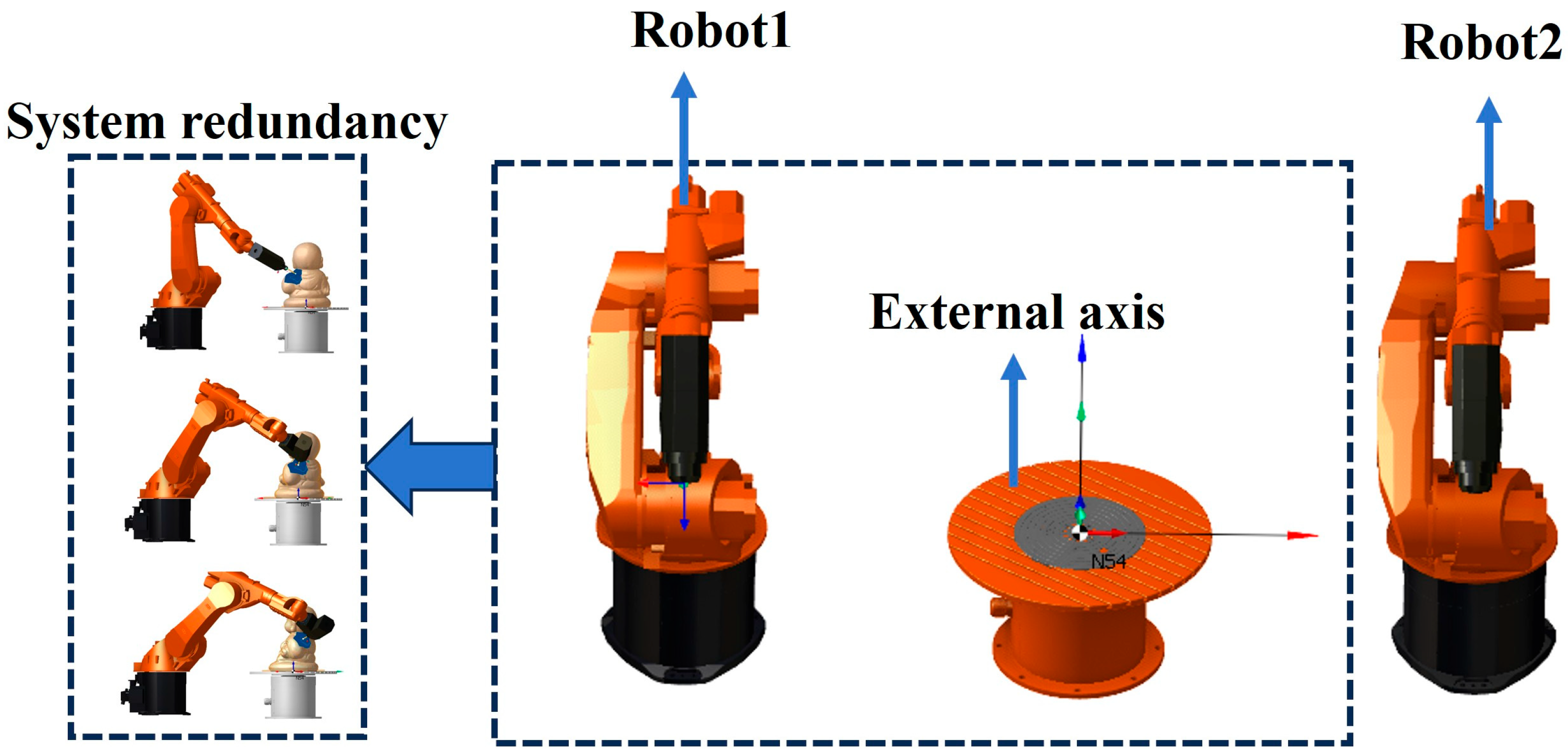
In summary, existing studies on multi-robot task allocation and coordinated scheduling cover a wide range of system morphologies— including “robot and workpiece both fixed,” “robot mobile,” and “workpiece mobile (with turntables/positioners)”—and have demonstrated good performance in industrial applications such as welding, assembly, and additive manufacturing. However, their typical assumptions generally target regular structures and uniform task granularity within a relatively well-controlled workspace, which makes them difficult to transfer directly to high-difficulty machining scenarios involving complex curved surfaces with large curvature variation and simultaneous reachability and stiffness constraints. The dual robot carving system (DRCS) investigated in this work, as illustrated in Figure 2, structurally belongs to the third category, i.e., “robot-stationary–workpiece-mobile.” The system consists of two six-axis industrial robots and an external axis (turntable). This configuration not only improves flexibility and reachability when machining complex workpieces, but also provides multi-station redundancy and posture coordination capabilities. Compared with prior work, which predominantly considers translational workpiece motion and only rarely includes turntable rotation (with workpieces different from those in this paper), the dual-robot-plus-turntable configuration studied here exhibits several clear gaps: (i) in the presence of complex free-form surfaces, multi-station redundancy causes the combined “task–station–posture” space to grow exponentially, and there is a lack of prior reachability- and stiffness-based filtering/decoupling strategies to reduce solution complexity and enhance implementability; (ii) within the third paradigm, integrated modeling that simultaneously captures external-axis participation, cross-station redundancy, and task allocation remains limited, with a particular shortage of methods for multi-robot, multi-station coupling that explicitly include a turntable; (iii) most existing studies take processing time as the single core objective, with insufficient system-level integration of posture stiffness and surface-quality-related process constraints. Therefore, for complex workpieces—especially hard-to-cut materials with high hardness—there is an urgent need for a task-allocation modeling and solution framework that jointly accounts for stiffness constraints and time efficiency.
To validate the suitability of the DRCS in complex, high-precision machining scenarios, this study adopts three-dimensional stone carving as a representative application task. Three-dimensional stone sculptures are characterized by intricate geometries, severe curvature variations, large dimensional spans, and high material hardness; they not only possess substantial cultural value but also impose stringent technical requirements on the machining system [30,31]. On the one hand, such operations require maintaining stable, high-stiffness postures in high-curvature regions to reduce subsequent finishing costs; on the other hand, they demand multi-directional reachability and flexible station switching to adequately cover fine details. By exploiting dual-robot cooperation and a multi-station machining architecture, the DRCS can enhance overall efficiency while preserving accuracy, thereby closely matching the demand for large-scale, high-quality automated production of stone sculptures.
In response to these challenges, this study proposes a dual-robot task allocation method for stereoscopic stone carving that incorporates stiffness performance constraints. By constructing a workstation optimization model with average normal stiffness as the evaluation metric, the method first identifies the most suitable workstation for each task, thereby effectively decoupling the task allocation problem while ensuring sufficient stiffness for critical operations. On this basis, two task allocation strategies are designed: one based on machinability and the other on machining time balancing. Their effectiveness is validated through comparative experiments. The results show that the machining time balancing strategy can significantly reduce the overall processing cycle and offers a clear advantage in improving system efficiency.

2. Experimental Conditions

2.1. Description of the Dual-Robot Carving System

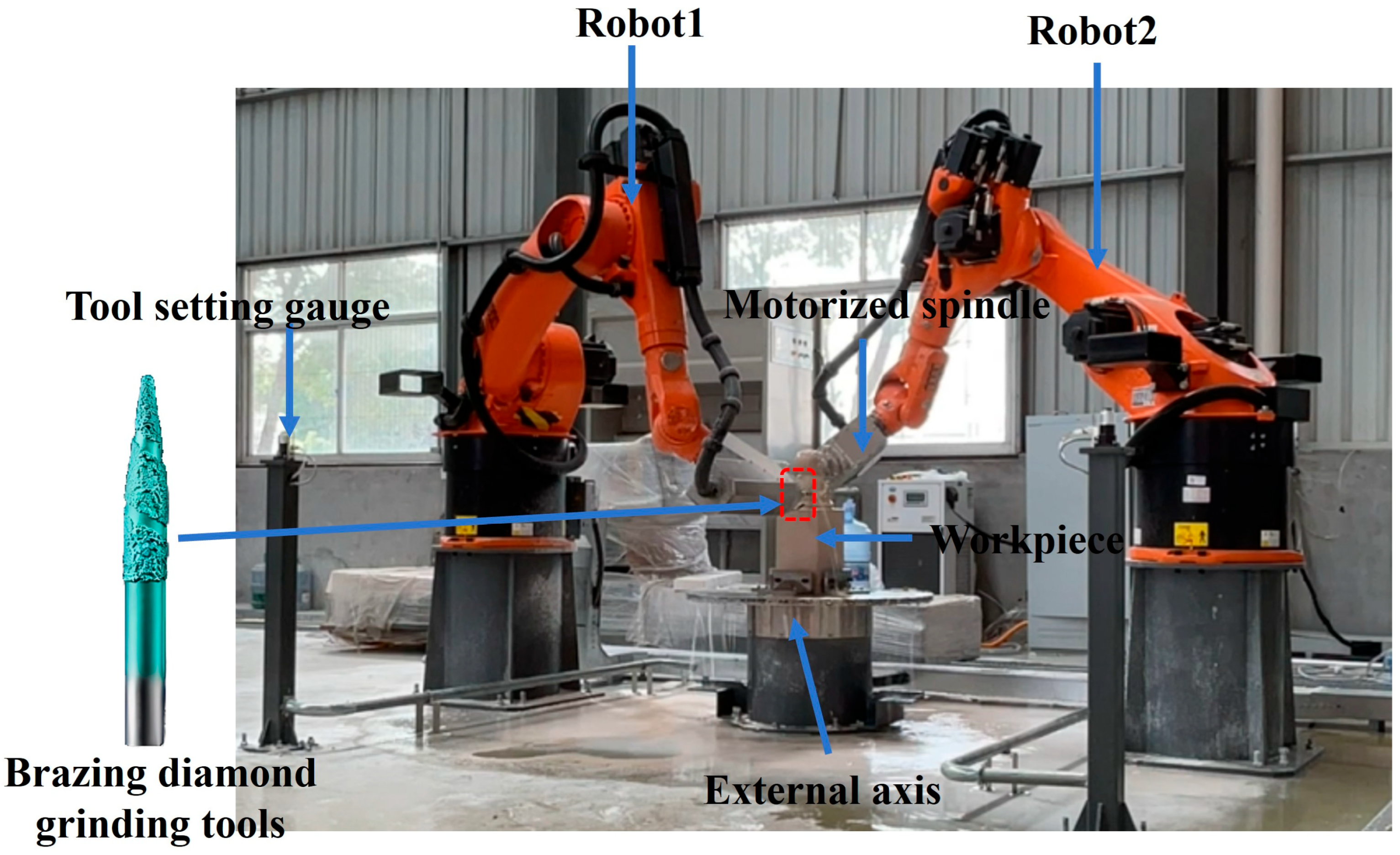
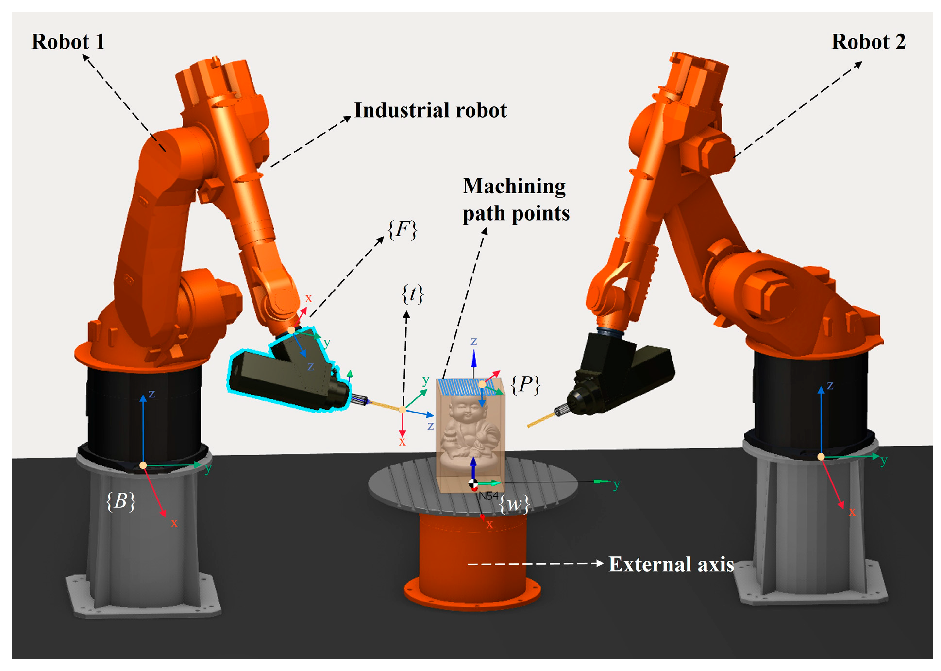
The dual-robot carving system used in this study is shown in Figure 3. The main components of the system consist of two KUKA KR60 robots and an external axis turntable, with the turntable positioned between the two robots. Any robot in the system can be combined with the turntable to form a single-robot carving system. Each robot has a maximum load capacity of 60 kg, a repeatability accuracy of 0.06 mm, and a maximum working range of 2033 mm. The spindle model is ZHUOHUI ZH-BT30-7.5, with an output power of 5.5 kW, a maximum speed of 24,000 rpm, and a maximum torque of 6.5 Nm. The external motion axis has a rated load capacity of 1T, with a turntable horizontal height of 550 mm, a table diameter of 800 mm, and a maximum rotation speed of 5 rpm. The tool used in this study is a brazed diamond tapered grinding head, with a shank diameter of 12 mm, a cutting length of 60 mm, and a tip diameter of 4 mm.
A dual-robot carving simulation platform was built using SprutCAM XV15 software to simulate and analyze the robot’s path planning. The software can simulate the robot’s motion in a real machining environment, correct potential issues such as interference, overrun, and singularities during the machining, avoiding problems in actual machining, reducing trial-and-error costs, and saving time. By importing the 3D model of the stone sculpture into the software, robot programming, simulation, and verification can be performed. The post-processing program for Kuka robots can compile the generated toolpath files into executable machining code for the robot. The dual-robot carving system developed in this study incorporates an external axis, enabling the machining tasks to change orientation as the external axis rotates, rather than remaining fixed. This configuration allows for diverse task allocation schemes, even in opposite-side operations. Based on this, the working range of each robot is constrained to a 180° sector on either side of the workpiece, which effectively prevents collisions during the machining process.
The usage method of the dual-robot system is as follows: rotate the external axis angle and assign feasible tasks to the two robots at the workstation. For workstations with different machining times on each side, the robot that finishes first waits until the other robot completes the task. Then, rotate the external axis for the next operation, and repeat the process until all tasks are completed. Therefore, the key to improving system efficiency lies in task allocation.

2.2. Machining Model and Parameters

2.2.1. Machining Model

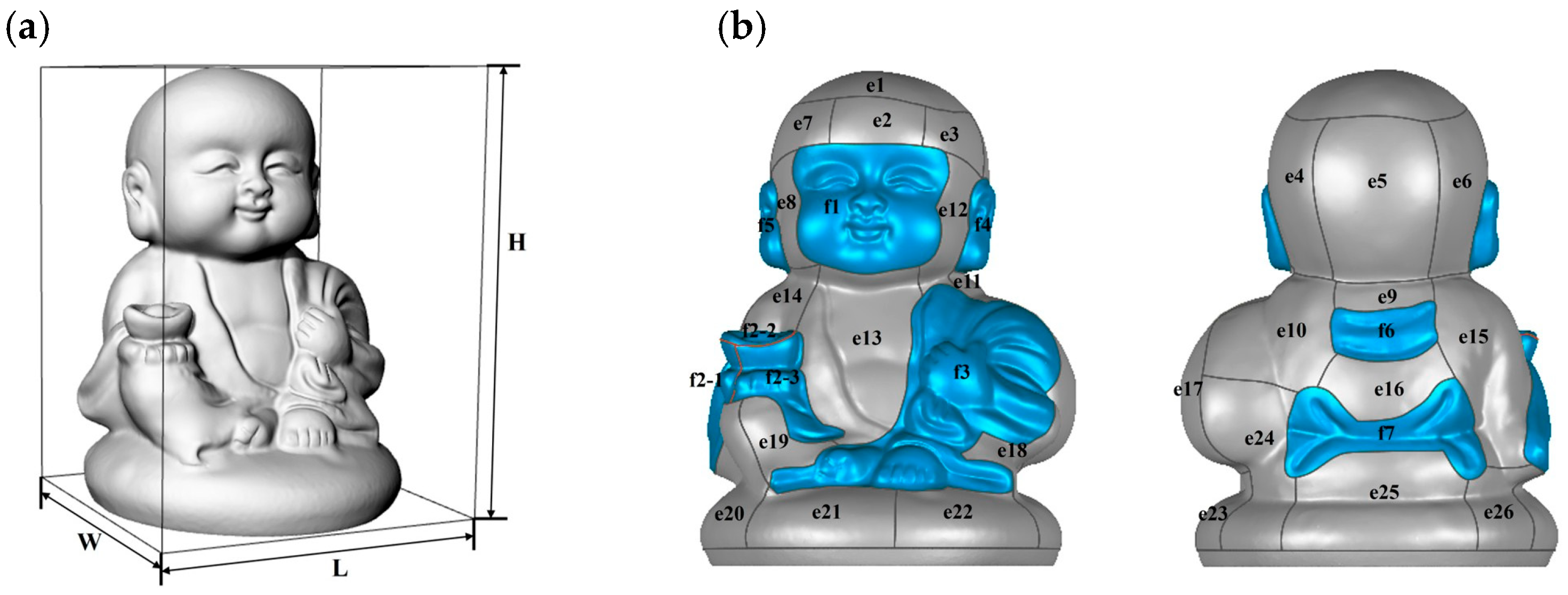
The carving model selected for this study is shown in Figure 4a. The model dimensions are: L = 188 mm, W = 179 mm, and H = 247 mm. The model is in STL format, and the carving material is limestone. Based on the surface Gaussian curvature and normal vector variation characteristics of the three-dimensional stone carving model, the model is divided into machining tasks, as shown in Figure 4b. The blue areas in the figure represent regions with large curvature variations, with task numbers f1 to f7, while the gray areas represent regions with small curvature variations, with task numbers e1 to e26. The set of all tasks provides the data input for the subsequent task allocation study.
To facilitate the subsequent task allocation for the divided tasks, a quantitative analysis of the machining task complexity is required. The complexity C is defined by the following calculation formula:
C = λ m s
where λ is a constant correction factor that keeps the magnitude of the complexity C within a comparable range among all tasks. In this study, λ is empirically determined according to the curvature characteristics of the selected stone carving model and remains unchanged during the operation.
m = i = 1 n G n n
m is the mean of the absolute Gaussian curvatures of all points in the task, reflecting the average Gaussian curvature level of the task.
s = i = 1 n G n m 2 n
s is the standard deviation of the absolute Gaussian curvatures of all points in the task, reflecting the degree of curvature variation in the task.
n is the number of task points, and G n is the Gaussian curvature at the n -th point.
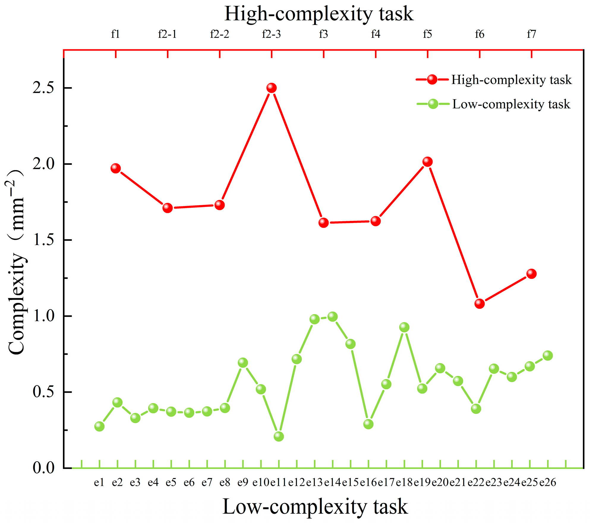
The complexities of tasks f1 to f7 and e1 to e26 are calculated using the formulas, as shown in Figure 5. It was observed that the complexities of tasks f1–f7 are greater than 1 and are thus defined as high-complexity tasks, while those of tasks e1–e26 are less than 1 and are defined as low-complexity tasks.

2.2.2. Machining Parameters

The machining process of three-dimensional stone carving can be divided into a roughing stage and a finishing stage. During the roughing stage, flat-end tools are used to rapidly remove a large volume of material and to produce the general shape of the model. In the finishing stage, ball-end tools are employed primarily to enhance surface precision and quality [32]. The task allocation method proposed in this study is specifically designed for the finishing stage of the stone carving process, where the machining depth is determined by the remaining material after roughing. In this study, the remaining material allowance is set to ap = 1 mm, with other machining parameters defined as follows: spindle speed n = 8000 r/min, feed rate f = 1000 mm/min, and cutting width ae = 0.5 mm.

2.3. Single-Robot Carving Experiment

This study uses a single-robot carving experiment for comparison. A single-robot carving system composed of Robot 2 and the turntable is used for regional finishing of the stone sculpture model. The machining parameters and tools are the same as those used in the dual-robot carving experiment. The machining regions correspond to the areas divided in Figure 5. In the single-robot machining mode, the machining posture for high-complexity tasks and the corresponding turntable angles are the same as in the dual-robot carving mode. The turntable angles are: 0°, −20°, 80°, −7°, and −108°. The five turntable angles (0°, −20°, 80°, −7°, and −108°) used in this study were selected based on the workstation optimization model incorporating stiffness performance (Section 3.1). These angles correspond to the optimal or near-optimal stiffness postures for the high-complexity tasks, ensuring sufficient machining stiffness while avoiding robot–workpiece interference. The carving process of the single robot is simulated using SprutCAM XV15 software, where the simulated machining time is recorded, and robot machining code is generated for the carving.

3. Task Allocation Method Under Stiffness Performance Constraints

Task allocation refers to the rational distribution of the task set from Section 2 to the two robots for machining. Due to workspace limitations, robots find it difficult to complete all tasks at the same workstation during the carving process. Even if completed, areas with poor kinematic or machining performance may occur, leading to a decline in machining quality. Therefore, optimal workstation selection is crucial. This study uses DRCS to process the aforementioned model. Task allocation and workstation optimization in DRCS are highly coupled. Therefore, this section proposes a task allocation method under stiffness performance constraints. The numerical parameters and case-specific values used to instantiate the proposed optimization model are provided in Section 2 and further analyzed in Section 4. Therefore, Section 3 focuses solely on the general formulation of the methodology.

3.1. Workstation Optimization Model Incorporating Stiffness Performance

3.1.1. Description of the Workstation Optimization Model Incorporating Stiffness Performance

During the robotic sculpting process, seams are prone to appear at the boundaries between different regions, primarily due to variations in the robot’s machining performance across different task areas. Normal-direction deformation is identified as the main factor contributing to this issue. Therefore, this section evaluates the machining performance of the robot at different postures using the normal stiffness performance index c n . The performance index is defined as follows [33]:
c n = e n T C t t e n
c n is the unit compliance in the e n direction, with a smaller value indicating lower compliance and higher stiffness. e n is a three-dimensional unit vector representing the surface normal direction. C t t is a 3 × 3 translational compliance matrix representing the displacement relationship of the robot’s end-effector in the x, y, and z directions under force, which is the inverse of the stiffness matrix. This equation shows that the normal stiffness performance of the robot depends on the robot’s posture and the normal direction. Once the carving model is determined, the normal direction at each point of the model is also fixed. When performing stiffness performance optimization, the machining quality of a single point cannot serve as the sole criterion for the quality of the entire surface machining. Therefore, this paper introduces the average normal stiffness performance indicator M c n , defined as
M c n = i = 1 n c n n
Discretely take n points within the machining task. The joint angles of the robot can be obtained by inverse solving based on the machining tool axis vector at each point, thereby obtaining the value of C t t . The maximum normal stiffness performance corresponding to each point is summed and averaged to represent the average normal stiffness performance of the machining region. The task is machined using the robot posture corresponding to the average normal stiffness performance. In stone-finishing operations, surface errors and boundary marks are mainly driven by deflection along the surface normal. The normal-projected translational compliance (Equation (4)) captures posture-dependent resistance to such deflection, and its task-level average (Equation (5)) provides a robust, region-level indicator that is comparable across workstations and less sensitive to local outliers.
DRCS can be regarded as two independent systems, each with seven degrees of freedom. For five-axis machining tasks, there are two redundant degrees of freedom. Changing the redundant angles still allows the completion of the predetermined tasks. In the previous section’s study, the stone carving model was decomposed into multiple sub-tasks, and each sub-task can be machined at multiple workstations. Therefore, the machining workstations can be quantified using stiffness indicators to find the external axis angle with optimal stiffness performance, while also avoiding interference and meeting singularity and reachability requirements.
Figure 6 shows the DRCS machining schematic and coordinate system definitions. The toolpath is equivalent to a discrete point set, {p}. { w } is the workpiece coordinate system, rigidly attached to the robot turntable and rotates with the turntable; {B} is the robot base coordinate system; {F} is the robot flange coordinate system; and {t} is the robot tool coordinate system.
The following transformation relationship can be derived:
T w B T P w = T F B T t F T P t
where t   is related to the spindle mounting position and tool size, and is known for a given task. w changes with the external axis angle. The right-hand side of Equation (6) is a robot kinematics problem. The position changes in the toolpath points relative to the robot base coordinate system affect the robot’s joint angles, which in turn influence the robot’s stiffness performance. Therefore, the variables in this problem are the external axis angle θ w and the redundant axis angle, with the objective function being the robot’s stiffness performance. The optimization problem can be described as: given the machining path and tool parameters, continuously changing the external axis angle and finding the robot joint angles that satisfy the objective. Thus, the objective function of the workstation optimization model is the robot’s stiffness indicator, which can also be defined as a function of the external axis angle and robot joint angles:
max M c n = f θ w , θ
where θ w represents the external axis angle, and θ represents the robot’s joint angles at each toolpath point.

3.1.2. Constraints of the Workstation Optimization Model Incorporating Stiffness Performance

In actual machining, robots typically need to perform tasks without interference, singularities, and with smooth operation. Therefore, constraints are required for the workstation optimization model. The constraint conditions are as follows:
1. Kinematic constraints: Joint angle ranges and joint speeds. The joint angle range affects the reachability of the toolpath points, and the joint speed affects the robot’s operation and machining smoothness. The constraints are as follows:
θ m i n + ϕ θ i θ m a x ϕ
θ i θ i 1 γ ω t
where θ i represents the joint angle at the i -th toolpath point. t is the time interval between two toolpath points. ϕ and γ are user-defined parameters that limit the boundary range. The introduction of these two parameters helps prevent joint movement from reaching the extreme positions, ensuring the continuity of the machining task.
2. Collision constraint: In this study, sparse processing is applied to the toolpath points, and collision detection is performed using the VREP4.0 software’s physics engine. For each candidate combination of external-axis angle and robot posture, the tool, spindle, robot links, and workpiece are imported into VREP4.0, and a discrete point set along the toolpath is used to check for mutual collisions. If any collision is detected, the collision indicator is set to 1; otherwise, it remains 0. The constraint is described as:
c o l l i s i o n = 0
3. External axis angle constraint: The DRCS robots used in this study are of the same model, and both robots are equidistant from the external axis, resulting in identical machining performance. Additionally, to avoid dual-robot collisions, each robot processes its designated side of the workpiece. When the optimal workstation for robot 1 machining is used, rotating it by 180° gives the optimal workstation for robot 2 machining. Therefore, this study will analyze the opposite side tasks by rotating them 180°, reducing the workstation optimization range for the robots. The constraint on the external axis angle is as follows:
0 θ w 18 0

3.2. Task Allocation Method for Workstation Optimization Model

The task allocation method proposed in this section first determines the machining workstations based on the stiffness optimization for high-complexity tasks, ensuring optimal stiffness performance for these tasks. Then, low-complexity tasks are allocated to various workstations using two different methods.

3.2.1. Workstation Angle

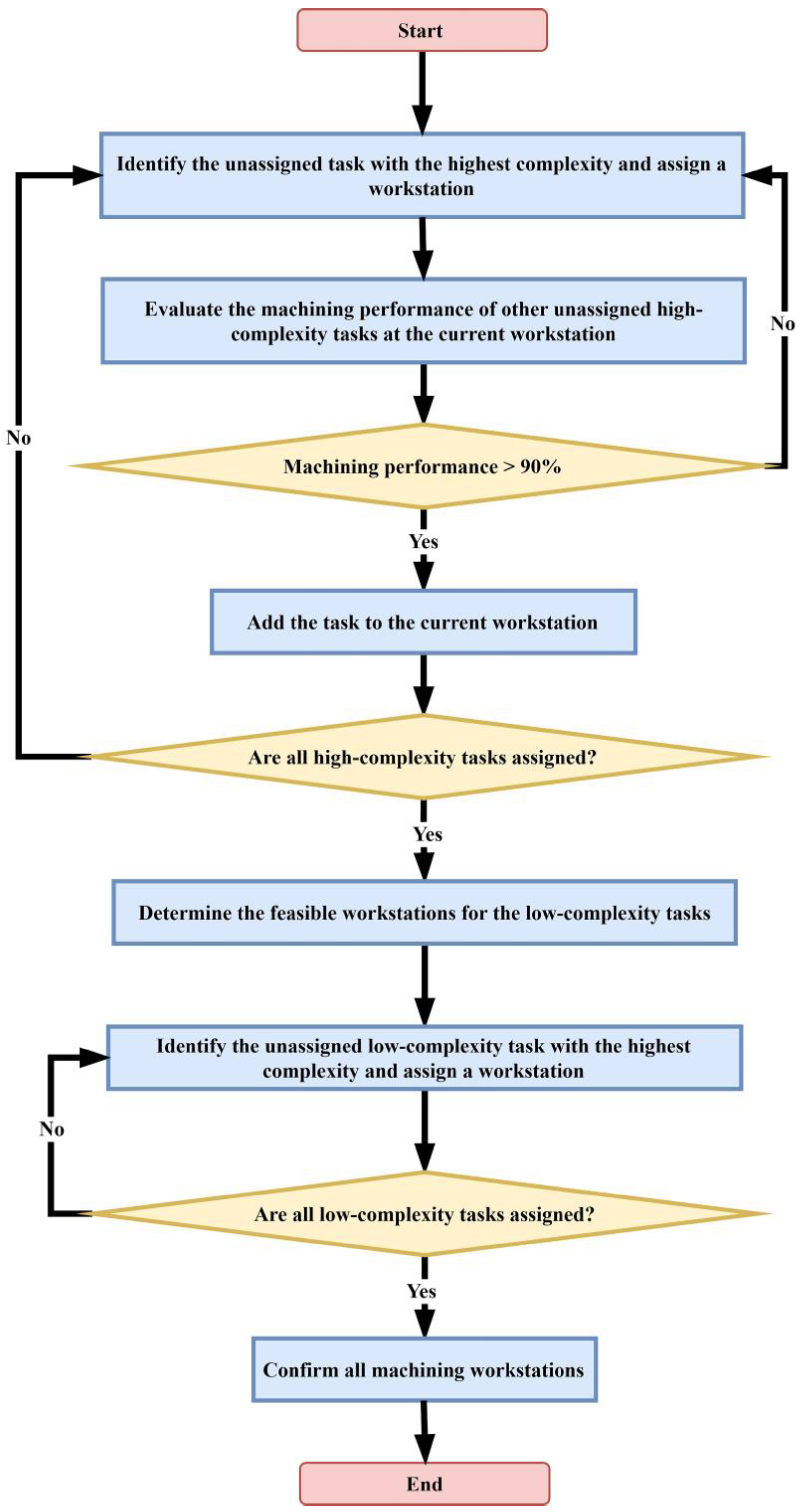
Based on the division of different machining regions of the stone carving model in Section 2, high-complexity regions exhibit large curvature variations. These variations significantly impact the overall appearance of the model. Additionally, the machining and manual repair of these regions are more difficult and have high quality requirements. Therefore, workstation determination primarily targets high-complexity tasks. In this study, the turntable angle is discretized at 1° intervals. The machining stiffness performance for each angle is then solved individually. The workstation angle with better stiffness performance is selected using the workstation optimization model, ensuring machining quality. At the same time, the determination of workstations decouples the complex problem, reducing the difficulty of subsequent task allocation. The workstation determination flowchart is shown in Figure 7.
Workstations are determined sequentially based on task complexity. The specific steps are as follows:
Step 1: Identify the most complex task among the high-complexity tasks, and determine the turntable angle based on the workstation that offers its maximum stiffness performance.
Step 2: Evaluate the stiffness performance of other unassigned high-complexity tasks at the current workstation.
Step 3: Determine whether the stiffness performance of the other unassigned tasks at this workstation exceeds that of 90% of alternative workstations. The “90%” rule is a tunable hyper-parameter that trades binding confidence against allocation diversity: lowering it binds more high-complexity tasks to early stations (risking imbalance), whereas raising it defers assignments (risking fragmentation). Within a reasonable band (≈85%–92%) in our setting, the selected station set remained stable: variations mainly affected the per-station task counts rather than the chosen stations.
Step 4: If so, assign the task to the current workstation; otherwise, return to Step 1.
Step 5: Check whether all high-complexity tasks have been allocated. If yes, proceed to the next step; otherwise, return to Step 1.
Step 6: Use the workstation optimization model to identify feasible workstations for low-complexity tasks and obtain the corresponding feasible task sets for those workstations.
Step 7: For low-complexity tasks not yet assigned, determine the machining workstations using the optimization model in descending order of complexity.
Step 8: Check whether the determined workstations cover all machining tasks.
Step 9: If yes, workstation assignment is complete; otherwise, return to Step 7.

3.2.2. Workstation-Based Task Allocation Based on Machinability

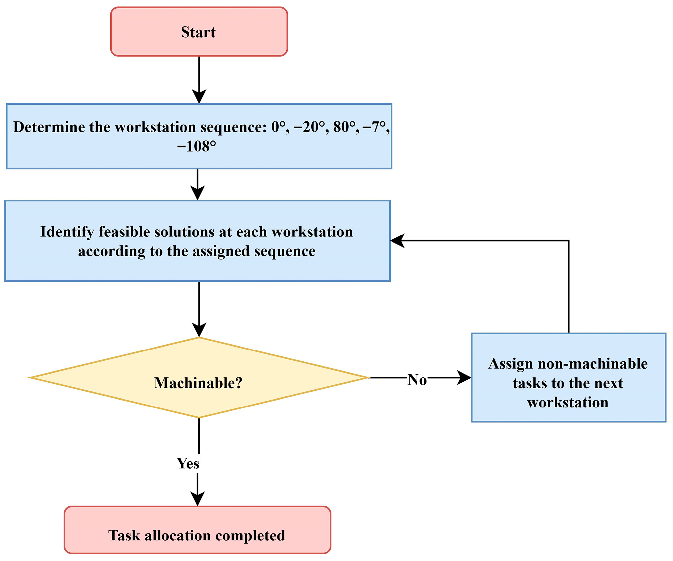
By allocating the high-complexity tasks, different machining workstations are determined, thereby decoupling the otherwise complex and interdependent task structure. The next step is to assign the low-complexity tasks to different workstations. As low-complexity tasks have lower requirements for machining performance, each task has multiple feasible workstation options. The remaining low-complexity tasks are allocated by considering only their machinability at different workstations and the potential for inter-robot interference. The task allocation procedure is illustrated in Figure 8.
The specific steps are as follows:
Step 1: Determine the sequence of workstations, 0°, −20°, 80°, −7°, and −108°, and perform subsequent task allocation in this order. This sequence directly follows from the workstation optimization in Section 3.1, Section 3.1.1, Section 3.1.2, Section 3.2 and Section 3.2.1: the five angles are first obtained as stiffness-optimized workstations for the high-complexity tasks. In the machinability-based strategy, this stiffness-informed sequence is kept fixed and used as a heuristic baseline without further optimization.
Step 2: Starting from the 0° workstation, identify feasible workstations for the remaining low-complexity tasks. Once a task is assigned to a workstation, remove it from the task set. Repeat this process until all tasks have been assigned.
Step 3: Check whether the assigned tasks will result in inter-robot interference or collisions during machining—i.e., verify their actual machinability.
Step 4: If all tasks are machinable, task allocation is complete. Otherwise, reassign unmachinable tasks to the next workstation in the sequence until all tasks become machinable and the allocation is finalized.
Since the two KUKA KR60 robots in the DRCS are identical and are symmetrically arranged with respect to the external axis, each robot is responsible for its own 180° sector of the workpiece. Under the machinability-based strategy, the five stiffness-optimized workstation angles ( 0 , 20 , 80 , 7 , 108 ) obtained in Section 3.1 are kept as a fixed sequence. Low-complexity tasks are assigned by scanning this sequence in order: at each workstation, all remaining tasks that are reachable and collision-free for the corresponding robot–turntable–workpiece configuration are allocated, while unmachinable tasks are deferred to the next workstation. As a result, task allocation is determined purely by geometric feasibility and collision constraints.

3.2.3. Workstation-Based Task Allocation Based on Machining Time Balancing

Once the workstations are determined, each remaining task generally has multiple feasible workstation options, forming a large-scale feasible solution set through various combinations. Compared to the machinability-based workstation task allocation method, this paper proposes a task allocation method based on machining time balancing, with the objective of minimizing the sum of task time differences between the two robots across all workstations, which essentially constitutes a combinatorial optimization problem for finding the optimal solution.
This section employs the simulated annealing algorithm for combinatorial optimization. First, define the robot set as R = {1,2}, and the set of workstations as C = {1,2,…,k}. The feasible solution set for each workstation is defined as Q = {Rij}, i ∈ C, j ∈ R. The task set at each workstation is defined as S = {Sij}, i ∈ C, j ∈ R. The machining time set for high-complexity tasks is t c = { t c 1 ,   t c 2 ,   t c 3 ,   ,   t c p } . The machining time set for low-complexity tasks is t n = { t n 1 ,   t n 2 ,   t n 3 ,   ,   t n q } . The set of workstation times is defined as T = {Tij}, i ∈ C, j ∈ R. Here, k is the number of machining workstations; p is the number of high-complexity tasks; and q is the number of low-complexity tasks. Tij denotes the total machining time of robot j at workstation i. In this study, the machining times of individual tasks are obtained from offline toolpath simulations in SprutCAM XV15 under the finishing parameters specified in Section 2.2.2. These simulated times serve as the input data for the time-balancing objective in the proposed combinatorial optimization model. Rij is the feasible solution set of robot j at workstation i. Let U denote the total sum of task time differences between the two robots across all workstations. Therefore, the task allocation problem can be formulated as:
min U = i = 1 k T i 1 T i 2
s t . S i j R i j S i j = t c + t n S i 1 S i 2 =
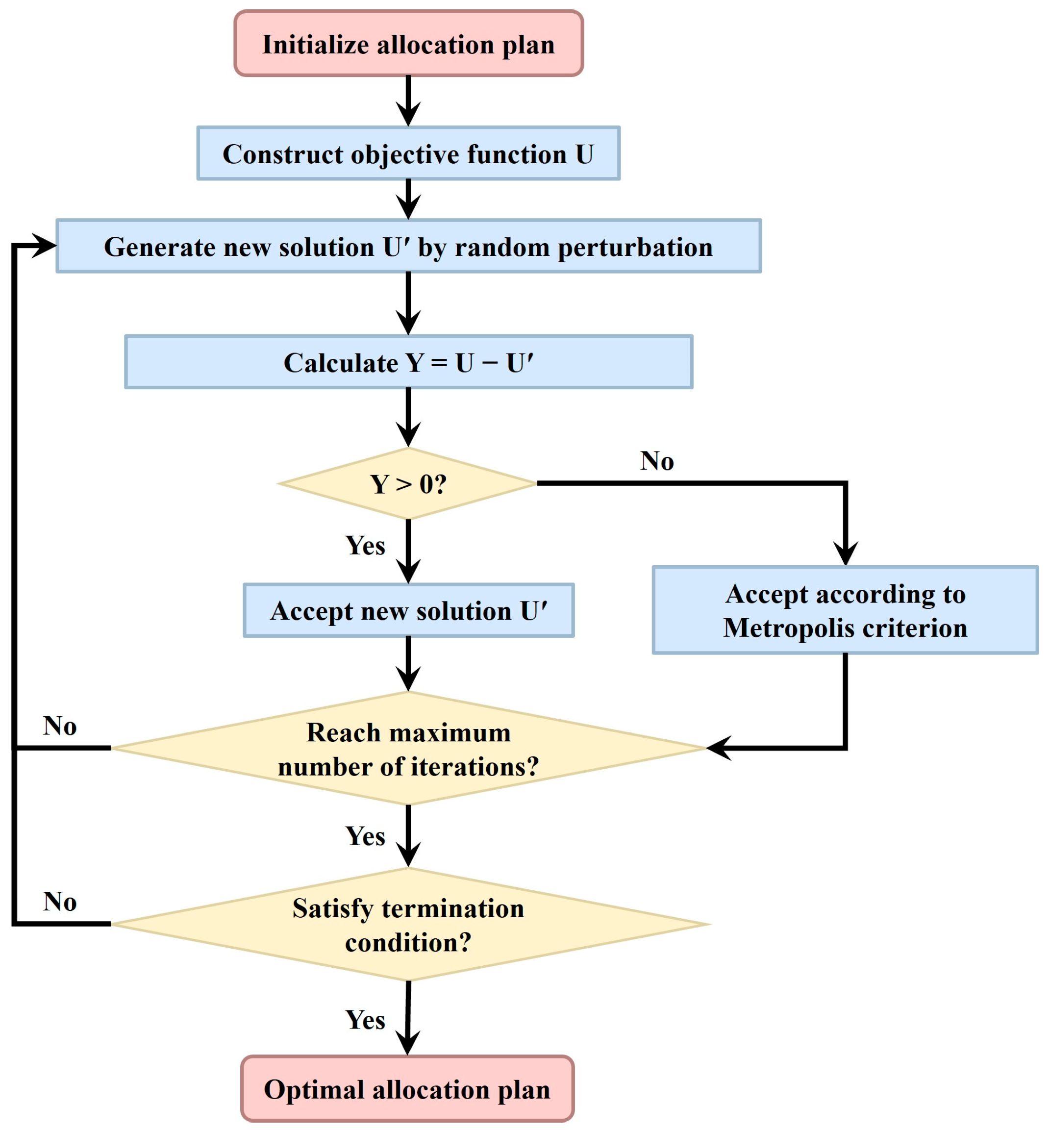
The workflow of the low-complexity task allocation algorithm is shown in Figure 9.
The specific steps are as follows:
Step 1: Encode the machining tasks as 1, 2, …, p + q. Then filter the feasible task set for each workstation Q = {Rij} by removing high-complexity tasks to obtain set Q1. An initial solution is generated from Q in the form of a three-dimensional array, where the first dimension represents the robot number, the second dimension represents the workstation number, and the third dimension represents the task code.
Step 2: Calculate U = i = 1 k T i 1 T i 2 based on the above array and set it as the initial value.
Step 3: Randomly select two workstation sets from Q1, compute their intersection, randomly exchange or move elements within the intersection, then calculate the new value   i = 1 k T i 1 T i 2 to obtain the new solution U′, and compute Y = U − U′.
Step 4: Determine whether Y is greater than zero. If it is, accept the new solution; otherwise, accept it with a certain probability.
Step 5: Repeat Steps 3 and 4 until the termination condition of the iteration is met.
Finally, check the machinability of the assigned tasks. If all tasks are machinable, the task allocation is complete. For unmachinable tasks, remove them from the current feasible workstation set and rerun the above task allocation algorithm until all tasks are successfully allocated.

4. Results and Discussion

4.1. Workstation Determination Results

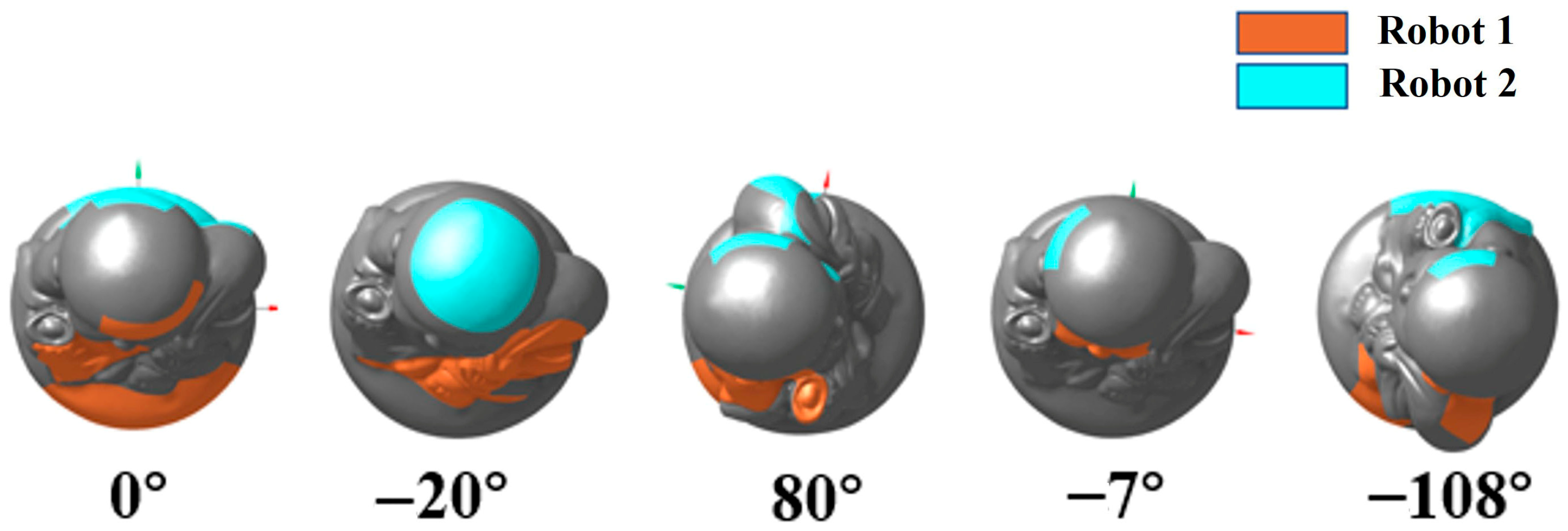
Based on the workstation optimization model, five turntable angles were ultimately selected for the workstations, in the following order: 0°, −20°, 80°, −7°, and −108°, as shown in Figure 10. Subsequently, a machinability check was conducted for the low-complexity regions, and the five workstations were found to fully cover all low-complexity tasks.
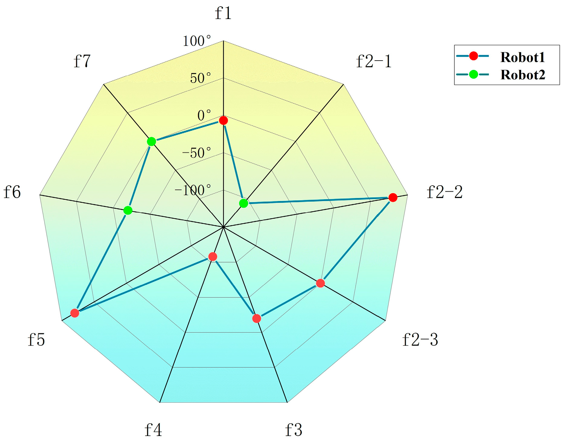
The determination of workstations also indicates that the high-complexity tasks have been assigned. The allocation results of high-complexity tasks are shown in Figure 11.
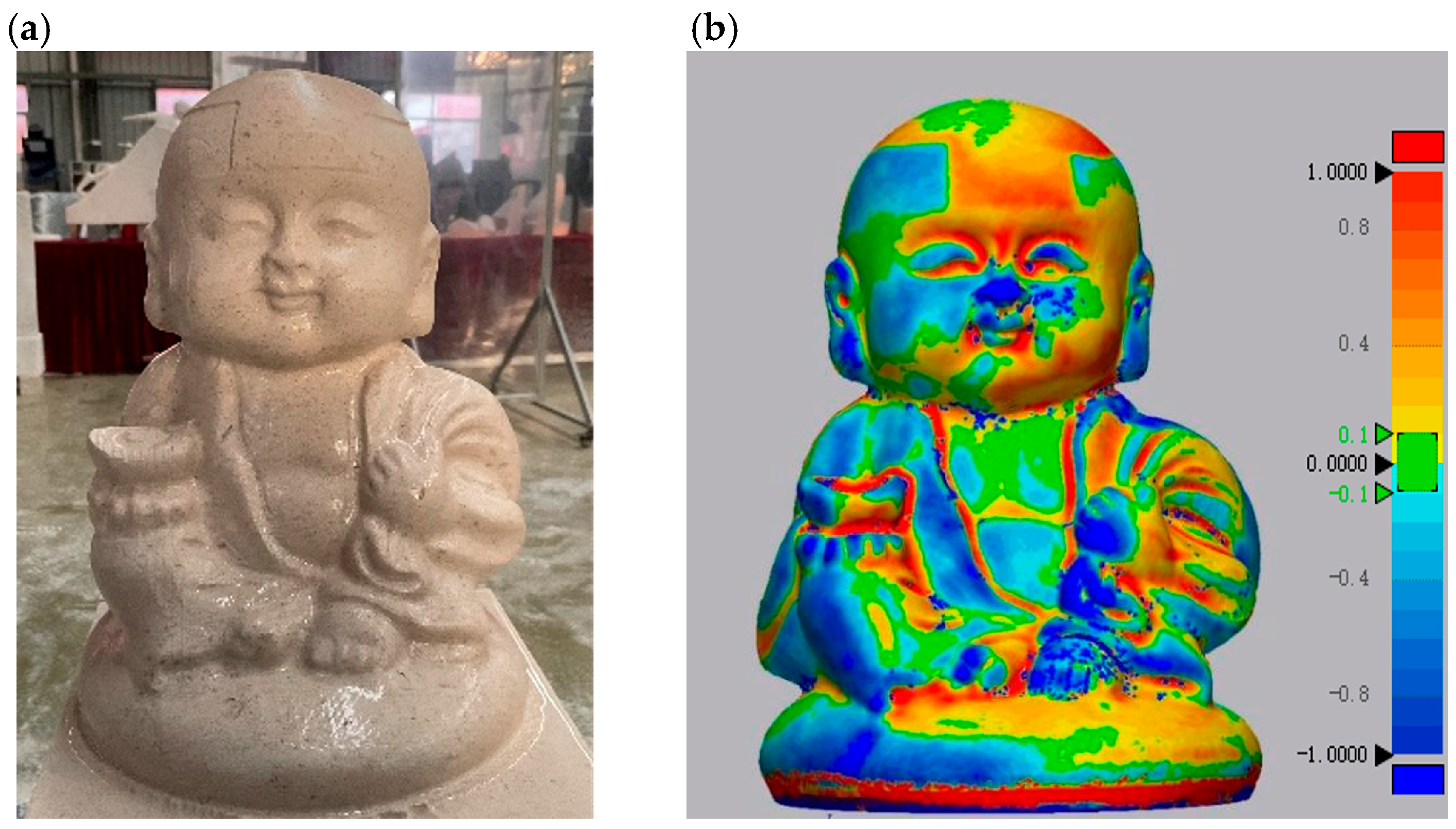
The task allocation method proposed in this paper was applied to the actual machining of the stone carving model. To evaluate the impact of the workstation optimization model incorporating stiffness performance on the quality of high-complexity tasks, a 3D scanner was used to scan the machined model and obtain its point cloud data. The surface quality was analyzed by comparing the scanned model with the target model. The machined stone carving model and the corresponding surface error analysis are shown in Figure 12a and Figure 12b, respectively.
An analysis of the boundary tool marks appearing at the top of the model was conducted. It was found that due to the non-homogeneous nature of the stone material, the robot experiences significant force fluctuations during machining. The resulting residual material is difficult to predict. Even under high-performance robot postures, errors can only be reduced—not eliminated—thus tool marks along task boundaries are inevitable.
The RMSE of the scanned surface was computed for the two task groups. For the high-complexity regions (f1–f7), the RMSE ranges from 0.36 to 0.62 mm, with an average of 0.49 mm. For the low-complexity regions (e1–e26), the RMSE ranges from 0.18 to 0.45 mm, with an average of 0.29 mm. All values remain well within the ±1 mm deviation range, meeting the standard for subsequent manual refinement.
From the perspective of the proposed allocation framework, these uncertainties are mitigated rather than explicitly controlled. By assigning high-complexity regions to workstations with higher average normal stiffness and balancing the machining time of the two robots, the sensitivity to force fluctuations is reduced and the resulting boundary errors are confined within an acceptable range.

4.2. Comparison of Machining Time Under Different Machining Methods

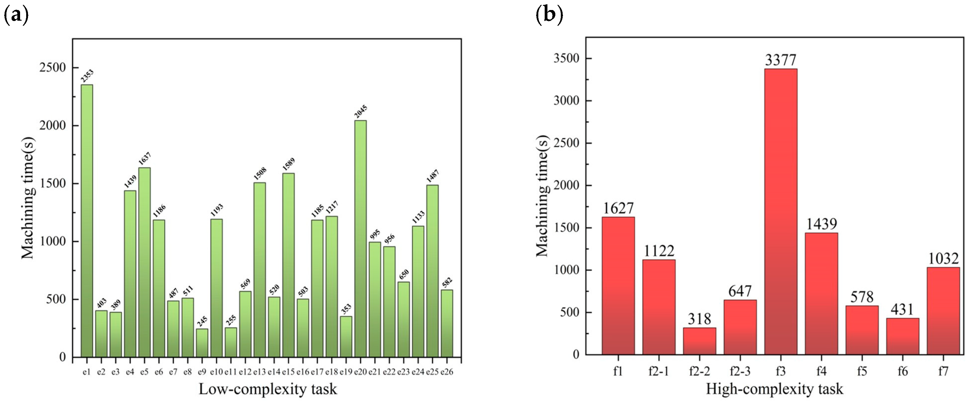
The machining time for each task was obtained through toolpath simulation using SprutCAM software. These simulated machining times correspond to the effective cutting time along the programmed toolpaths under the finishing parameters specified in Section 2.2.2 and do not include robot idle waiting or turntable indexing. The stone carving process operates at a relatively low speed and falls under the category of low-speed machining. Under conditions that ensure sufficient flexibility, machining time is not significantly affected by the robot’s joint speed or acceleration. Under the same machining strategy and parameters, the machining time for the same task is similar across different workstations. Therefore, machining time can be simulated and computed using any one of the feasible workstations. The machining time of each task obtained from SprutCAM XV15 simulation is shown in Figure 13.
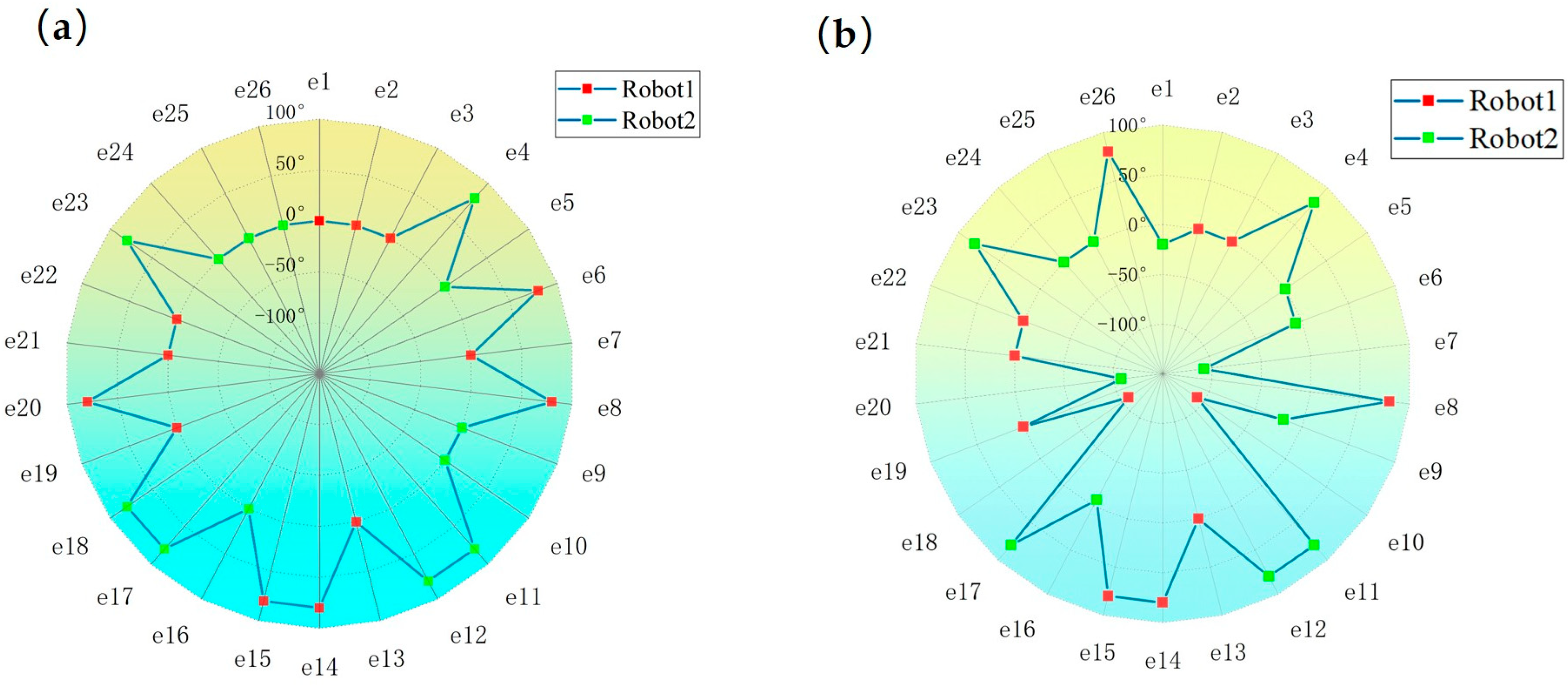
For dual-robot carving, the two methods proposed in Section 3 were respectively applied for the allocation of the remaining low-complexity tasks. The task allocation results are shown in Figure 14. Figure 14a presents the task allocation result based on machinability, while Figure 14b shows the task allocation result based on machining time balancing.
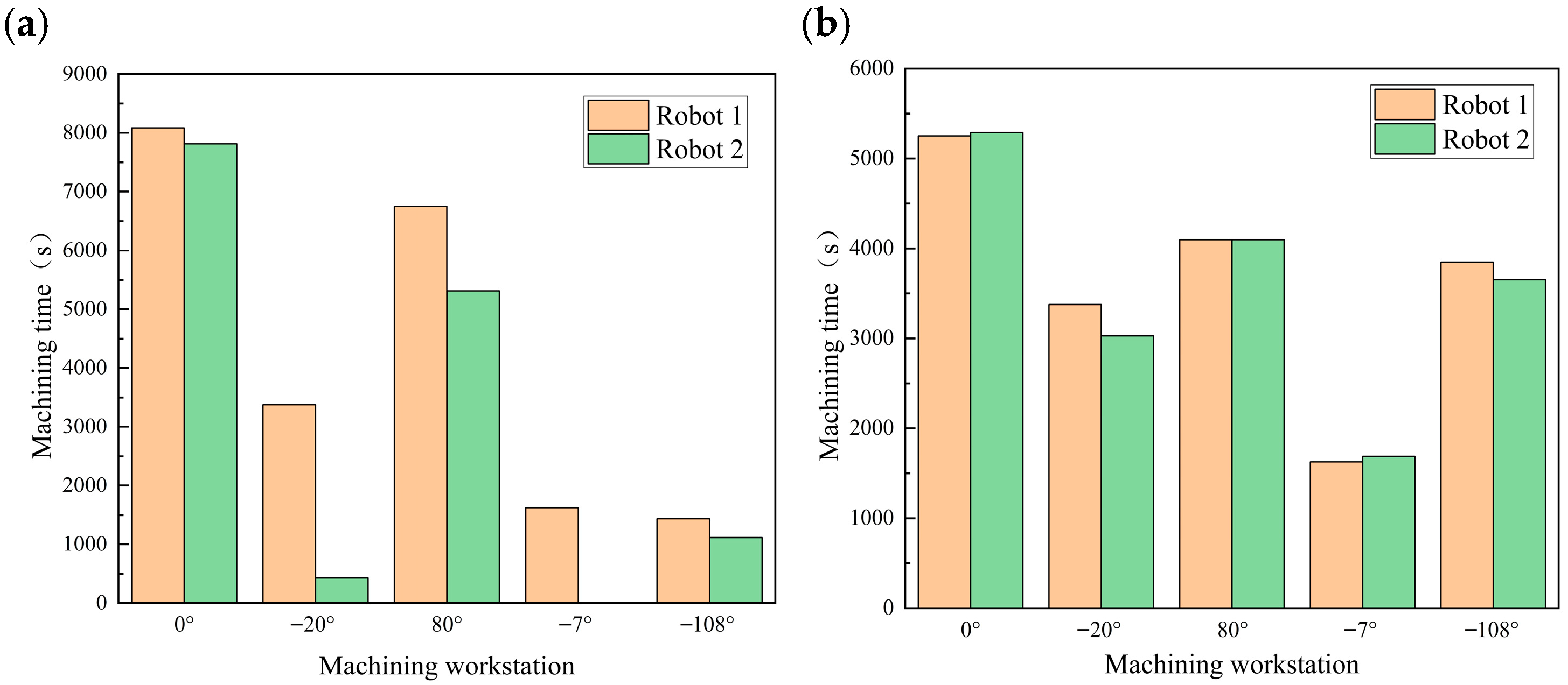
At this point, all machining tasks have been allocated. The machining time of each robot at each workstation was summed, and the task time differences between the two robots at each workstation are shown in Figure 15.
As shown in Figure 15a, when only machinability is considered in task allocation, the machining time difference between the two robots at each workstation is relatively large. As shown in Figure 15b, after considering time balancing, the machining times of the two robots at each workstation become more similar.
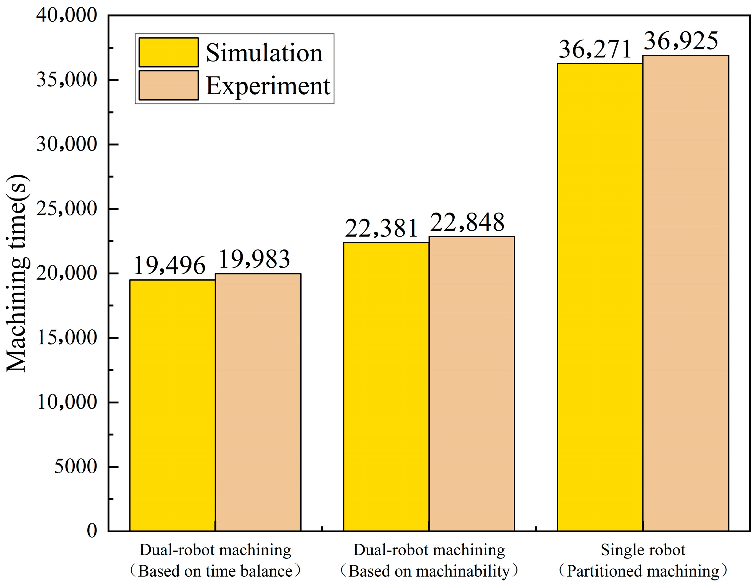
The machining times under the two task allocation methods and the single-robot partitioned machining mode were obtained through SprutCAM XV15 simulation, as shown in Figure 15. It can be seen that the machining time under the dual-robot mode with time-balancing task allocation is 19,496 s. The machining time under the machinability-based dual-robot mode is 22,381 s, and under the traditional single-robot partitioned machining mode, the machining time is 36,271 s. Comparison shows that using the time-balancing task allocation method improves machining efficiency by 14.79% compared to the machinability-based method and by 86.04% compared to the single-robot mode.
Finally, to further validate the effectiveness of the task allocation method proposed in this study, practical machining experiments were conducted using the three aforementioned machining strategies. The experiments were carried out using the Dual-Robot Carving System (DRCS). The actual machining times for the different strategies are shown in Figure 16. The machining times reported in Figure 16 refer to the full cycle time from the start to the completion of carving, and therefore include auxiliary operations such as turntable rotation, synchronization waits between the two robots, and non-cutting transitions. These auxiliary operations were implemented in the same manner for all three machining strategies, so the differences in experimental cycle time mainly reflect changes in robot idle time caused by different task allocation schemes. When task allocation time balancing was considered, the actual machining time using the dual-robot machining strategy was 19,983 s. Without considering time balancing—namely, based solely on machinability—the actual machining time for the dual-robot strategy was 22,848 s. In contrast, the traditional single-robot partitioned machining method required 36,925 s. Comparing the simulation and experimental machining times, the differences were relatively small. The primary sources of error were attributed to timing inaccuracies and imprecise transitional toolpath estimations, though these had minimal impact on the overall results. The experimental results demonstrated that, compared with the machinability-based task allocation method and the traditional single-robot partitioned machining approach, the use of the time-balancing task allocation method improved the actual machining efficiency by 14.33% and 84.78%, respectively.
The key to analyzing the improvement in machining efficiency lies in the difference in machining time between robots at each workstation. Through the balanced allocation method, the waiting time of a single robot at each workstation is shorter, reducing the waste of machining resources. By balancing the task time of the machining robots, machining efficiency can be effectively improved. Compared to the single-robot partitioned machining approach, ideally, the machining time of dual robots can be reduced by half relative to the single-robot approach. By applying the time-balancing task allocation method, the actual machining efficiency was improved by 84.78%, which is very close to the theoretical optimum.

5. Conclusions and Future Works

This study focuses on addressing the issue of low efficiency in three-dimensional stone carving. A task allocation method for dual-robot carving under stiffness performance constraints is proposed, which improves the machining efficiency of stone carving and reduces machining errors in detailed regions.
The main contributions are as follows:
(1)
To address the machining redundancy caused by the introduction of an external axis in the dual-robot carving system, a workstation optimization model is proposed to determine workstations, enabling the decoupling of the task allocation problem.
(2)
For the machining accuracy of high-complexity tasks in model segmentation, the proposed stiffness performance-integrated workstation optimization model ensures that these tasks are executed at workstations with better stiffness performance, thereby guaranteeing machining quality.
(3)
Considering the machining time balancing of dual robots at each workstation can significantly improve the efficiency of stone carving. The effectiveness of this method is validated through both simulation and physical experiments. Compared with the task allocation method without time balancing and the traditional single-robot partitioned machining approach, experimental results show efficiency improvements of 14.33% and 84.78%, respectively.
Despite the significant improvements in dual-robot efficiency and surface quality achieved by the proposed task allocation method, several limitations remain. First, experimental validation is confined to the finishing stage with fixed process parameters, which constrains generalizability to broader operating regimes. Second, although the method is demonstrated on a stereoscopic limestone stone carving, the complexity metric is geometry-based and can be recomputed for other free-form geometries; the correction factor, complexity thresholds, and admissible stiffness levels would need to be recalibrated for different geometries and materials. Moreover, the current method does not incorporate online monitoring or dynamic task reassignment when the actual machining time deviates from the planned value.
Future work will therefore extend validation to other machining stages and operating conditions with variable process parameters, and investigate adaptive tuning of complexity- and stiffness-related parameters for different workpieces and materials. In addition, force/torque and timing feedback will be integrated to enable local resequencing or partial task reallocation in the presence of pronounced disturbances, thereby further enhancing the generalizability and robustness of the proposed approach.

Author Contributions

All authors contributed to the study conception and design. J.C. was responsible for the manuscript writing and experimental operations. H.H. was responsible for manuscript review and editing. F.Y. was responsible for the conceptualization of the work. H.S. was responsible for the algorithm development. C.K. was responsible for the 3D scanning of the model. All authors have read and agreed to the published version of the manuscript.

Funding

This work was supported by the Fujian Province’s Major Science and Technology Special Projects (Grant No. 2024HZ025008); the Seventh Batch of High-level Talent Team Projects introduced in Quanzhou City (Grant No. 2024CT005); the National Natural Science Foundation of China (NSFC) General Program (Grant No. 52575495); and the State Key Laboratory of High-performance Precision Manufacturing (Grant No. 202507). We also extend our sincere thanks to those who contributed to the preparation of the instructions.

Data Availability Statement

The datasets used or analyzed during the current study are available from the corresponding author on reasonable request.

Conflicts of Interest

The authors declare no conflicts of interest.

References

  1. Yin, F.C.; Ji, Q.Z.; Wang, C.Z. Research on machining error prediction and compensation technology for a stone-carving robotic manipulator. Int. J. Adv. Manuf. Technol. 2021, 115, 1683–1700. [Google Scholar] [CrossRef]
  2. Ji, W.; Wang, L.H. Industrial robotic machining: A review. Int. J. Adv. Manuf. Technol. 2019, 103, 1239–1255. [Google Scholar] [CrossRef]
  3. Pantscharowitsch, M.; Moser, L.; Kromoser, B. A study of the accuracy of industrial robots and laser-tracking for timber machining across the workspace. Wood Mater. Sci. Eng. 2025, 20, 75–93. [Google Scholar] [CrossRef]
  4. Cao, Y.J.; Beltrame, G. VIR-SLAM: Visual, inertial, and ranging SLAM for single and multi-robot systems. Auton. Robots 2021, 45, 905–917. [Google Scholar] [CrossRef]
  5. Kyprianou, G.; Doitsidis, L.; Chatzichristofis, S.A. Towards the achievement of path planning with multi-robot systems in dynamic environments. J. Intell. Robot. Syst. 2021, 104, 15. [Google Scholar] [CrossRef]
  6. Zhou, Z.Y.; Liu, J.C.; Yu, J.Z. A survey of underwater multi-robot systems. IEEE/CAA J. Autom. Sin. 2022, 9, 1–18. [Google Scholar] [CrossRef]
  7. Murugappan, E.; Nachiappan, S.; Shams, R.; Mark, G.; Chan, H.K. Performance analysis of clustering methods for balanced multi-robot task allocations. Int. J. Prod. Res. 2022, 60, 4576–4591. [Google Scholar] [CrossRef]
  8. Mao, W.J.; Liu, Z.J.; Liu, H.; Yang, F.Z.; Wang, M.R. Research progress on synergistic technologies of agricultural multi-robots. Appl. Sci. 2021, 11, 1448. [Google Scholar] [CrossRef]
  9. Spensieri, D.; Carlson, J.S.; Ekstedt, F.; Bohlin, R. An iterative approach for collision free routing and scheduling in multirobot stations. IEEE Trans. Autom. Sci. Eng. 2016, 13, 950–962. [Google Scholar] [CrossRef]
  10. Tereshchuk, V.; Stewart, J.; Bykov, N.; Pedigo, S.; Devasia, S.; Banerjee, A.G. An efficient scheduling algorithm for multi-robot task allocation in assembling aircraft structures. IEEE Robot. Autom. Lett. 2019, 4, 3844–3851. [Google Scholar] [CrossRef]
  11. Behrens, J.K.; Lange, R.; Mansouri, M. A constraint programming approach to simultaneous task allocation and motion scheduling for industrial dual-arm manipulation tasks. In Proceedings of the 2019 IEEE International Conference on Robotics and Automation (ICRA), Montreal, QC, Canada, 20–24 May 2019; pp. 8705–8711. [Google Scholar] [CrossRef]
  12. Wu, R.J.; Yin, Y.C.; Xu, K. Multi-task collaborative modeling and assignment method of manipulator. Mech. Sci. Technol. Aerosp. Eng. 2020, 39, 433–437. [Google Scholar] [CrossRef]
  13. Jia, X.H.; Tang, C.R.; Zhang, X.B.; Liu, J.Y. Research on dual robot collaboration method based on improved double ant colony algorithm. Ind. Robot. 2024, 51, 424–435. [Google Scholar] [CrossRef]
  14. Li, Y.Z.; Meng, L.Y.; Li, M.L.; Zhou, Y.J.; Liu, X.C.; Li, X.L.; Zhang, G.J. Allocation and scheduling of deposition paths in a layer for multi-robot coordinated wire and arc additive manufacturing of large-scale parts. Virtual Phys. Prototyp. 2024, 19, e2300680. [Google Scholar] [CrossRef]
  15. Liu, W.B.; Kuang, Z.A.; Zhang, Y.C.; Zhou, B.; He, P.F.; Li, S.H. An effective hybrid genetic algorithm for the multi-robot task allocation problem with limited span. Expert Syst. Appl. 2025, 280, 127299. [Google Scholar] [CrossRef]
  16. Lee, J.; Kim, B.I.; Nam, M. Novel method for welding gantry robot scheduling at shipyards. Int. J. Prod. Res. 2023, 61, 5842–5859. [Google Scholar] [CrossRef]
  17. Yu, R.; Chen, Y.Y. Coordinated ship welding with optimal lazy robot ratio and energy consumption via reinforcement learning. J. Mar. Sci. Eng. 2024, 12, 1765. [Google Scholar] [CrossRef]
  18. Liu, S.R.; Tian, W.; Shen, J.X.; Li, B.; Li, P.C. Base position and task assignment optimization concerning productivity and machining performance for multi-robot systems in aerospace manufacturing. Robot. Auton. Syst. 2024, 171, 104536. [Google Scholar] [CrossRef]
  19. Zhao, G.B.; Wu, J.H. Multi-station and multi-robot welding path planning based on greedy interception algorithm. In Proceedings of the 2020 IEEE/ASME International Conference on Advanced Intelligent Mechatronics (AIM), Boston, MA, USA, 6–9 July 2020; pp. 1190–1195. [Google Scholar] [CrossRef]
  20. Zhou, B.; Zhou, R.; Gan, Y.H.; Fang, F.; Mao, Y.J. Multi-robot multi-station cooperative spot welding task allocation based on stepwise optimization: An industrial case study. Robot. Comput.-Integr. Manuf. 2022, 73, 102197. [Google Scholar] [CrossRef]
  21. Bozma, H.I.; Kalalıoğlu, M.E. Multirobot coordination in pick-and-place tasks on a moving conveyor. Robot. Comput.-Integr. Manuf. 2012, 28, 530–538. [Google Scholar] [CrossRef]
  22. Arbogast, A.; Nycz, A.; Noakes, M.W.; Wang, P.; Masuo, C.; Vaughan, J.; Love, L.; Lind, R.; Carter, W.; Meyer, L.; et al. Strategies for a scalable multi-robot large scale wire arc additive manufacturing system. Addit. Manuf. Lett. 2024, 8, 100183. [Google Scholar] [CrossRef]
  23. Wang, Y.; Wang, X.; Chen, S.; Gu, X. Multi-station multi-robot welding system planning and scheduling based on STNSGA-D: An industrial case study. IEEE Trans. Autom. Sci. Eng. 2024, 21, 7465–7479. [Google Scholar] [CrossRef]
  24. Xiao, J.; Huang, K.; Terzi, S.; Bandinelli, R. Towards uncertainty of end-of-use product recycling: A general screw connection-oriented disassembly analysis. Int. J. Prod. Res. 2025, 1–24. [Google Scholar] [CrossRef]
  25. Xiao, J.; Zhang, Z.; Terzi, S.; Tao, F.; Anwer, N.; Eynard, B. Multi-scenario digital twin-driven human-robot collaboration multi-task disassembly process planning based on dynamic time petri-net and heterogeneous multi-agent double deep Q-learning network. J. Manuf. Syst. 2025, 83, 284–305. [Google Scholar] [CrossRef]
  26. Xiao, J.; Zhang, Z.; Terzi, S.; Anwer, N.; Eynard, B. Dynamic task allocations with Q-learning based particle swarm optimization for human-robot collaboration disassembly of electric vehicle battery recycling. Comput. Ind. Eng. 2025, 204, 111133. [Google Scholar] [CrossRef]
  27. Xiao, J.; Gao, J.; Anwer, N.; Eynard, B. Multi-agent reinforcement learning method for disassembly sequential task optimization based on human–robot collaborative disassembly in electric vehicle battery recycling. J. Manuf. Sci. Eng. 2023, 145, 121001. [Google Scholar] [CrossRef]
  28. Chen, L.; Wang, Z.; Mo, Y.; Pan, H. The path planning of synchronous cooperative motion control between robot and positioner for complex space curve processing. Electronics 2020, 9, 1917. [Google Scholar] [CrossRef]
  29. Kang, C.; Jia, H.; Zhao, E.; Ma, C. Development of an improved stiffness ellipsoid method for precise robot-positioner collaborative control in friction stir welding. Materials 2025, 18, 1852. [Google Scholar] [CrossRef] [PubMed]
  30. Unger, K. Carving his own unique niche, in symbols and stone. Science 2006, 314, 412–413. [Google Scholar] [CrossRef]
  31. Wang, H.F.; Luo, Y.Q.; An, C.D.; Chu, S.N.; Shen, Z.X.; Huang, L.X.; Zhang, D.Y. Application of imaging polarimeters to enhanced detection of stone carving. J. Cult. Herit. 2019, 40, 92–98. [Google Scholar] [CrossRef]
  32. Yin, F.C.; Wu, S.T.; Huang, H.; Cui, C.C.; Ji, Q.Z. Effect of machining trajectory on grinding force of complex-shaped stone by robotic manipulator. Machines 2022, 10, 787. [Google Scholar] [CrossRef]
  33. Chen, C.; Peng, F.; Yan, R.; Li, Y.; Wei, D.; Fan, Z.; Tang, X.; Zhu, Z. Stiffness performance index-based posture and feed orientation optimization in robotic milling process. Robot. Comput.-Integr. Manuf. 2019, 55, 29–40. [Google Scholar] [CrossRef]
Figure 1. Relative motion relationships between robots and workpieces: (a) Robots fixed–Workpiece fixed; (b) Robots mobile–Workpiece fixed; (c) Robots fixed–Workpiece mobile.
Machines 13 01097 g001
Figure 2. Schematic diagram of the dual-robot sculpting system.
Machines 13 01097 g002
Figure 3. Dual-robot carving system.
Machines 13 01097 g003
Figure 4. Stone carving model: (a) Model scale; (b) Dividing machining tasks.
Machines 13 01097 g004
Figure 5. Complexity of each machining task.
Machines 13 01097 g005
Figure 6. Machining schematic diagram and coordinate system representation.
Machines 13 01097 g006
Figure 7. Flow chart of station determination.
Machines 13 01097 g007
Figure 8. Task allocation process based on machinability.
Machines 13 01097 g008
Figure 9. Flow chart of task allocation algorithm based on machining time balance.
Machines 13 01097 g009
Figure 10. Angle of working station.
Machines 13 01097 g010
Figure 11. High-complexity task allocation results.
Machines 13 01097 g011
Figure 12. Task model experimental results: (a) The model after carving; (b) Model surface error.
Machines 13 01097 g012
Figure 13. Machining time of each task: (a) Low complexity task machining time; (b) High complexity task machining time.
Machines 13 01097 g013
Figure 14. Low complexity task allocation results: (a) Based on machinability; (b) Based on time balance.
Machines 13 01097 g014
Figure 15. Task time difference in each station: (a) Based on machinability; (b) Based on time balance.
Machines 13 01097 g015
Figure 16. Comparison of machining time of different machining methods.
Machines 13 01097 g016
Disclaimer/Publisher’s Note: The statements, opinions and data contained in all publications are solely those of the individual author(s) and contributor(s) and not of MDPI and/or the editor(s). MDPI and/or the editor(s) disclaim responsibility for any injury to people or property resulting from any ideas, methods, instructions or products referred to in the content.