Review

A Comprehensive Review of Theoretical Advances, Practical Developments, and Modern Challenges of Autonomous Unmanned Ground Vehicles

by
Rosario La Regina
1,
Ömer Ekim Genel
2,
Carmine Maria Pappalardo
3,* and
Domenico Guida
3
1
MEID4, Research Center for AI-based Innovation, Battipaglia, 84091 Salerno, Italy
2
Altayçeşme mah. Sarıgül sk. 9B, 34843 Maltepe, İstanbul, Türkiye
3
Department of Industrial Engineering, University of Salerno, Via Giovanni Paolo II 132, Fisciano, 84084 Salerno, Italy
*
Author to whom correspondence should be addressed.
Machines 2025, 13(12), 1071; https://doi.org/10.3390/machines13121071
Submission received: 4 October 2025 / Revised: 8 November 2025 / Accepted: 10 November 2025 / Published: 21 November 2025
(This article belongs to the Section Vehicle Engineering)

Abstract

The recent integration of Unmanned Ground Vehicles (UGVs) into human activities represents a significant scientific advancement and technological development, with substantial impacts across various fields, not limited to mechanical engineering, including agriculture, defense, and civil construction. Therefore, this study aims to provide a practical methodological framework, developed through a historical and systematic literature review, to emphasize the general criteria and the main interactions that an engineer should consider in the initial design phase of a UGV, thereby subsequently proceeding with its computer-aided modeling and simulation. To this end, a systematic literature review is conducted to identify current research interests in this field and pinpoint potential research gaps. Following the systematic literature review presented in this study, the focus of the present investigation shifts to classifying UGVs by analyzing their characteristics based on specific criteria, including weight, type of steering system, and wheel and track configurations. Additionally, the differences between wheels and tracks are further examined by comparing these two solutions and highlighting their advantages and limitations. This review paper also addresses power systems, hardware components, and navigation challenges. Subsequently, the primary sectors and applications where these vehicles are widely utilized are thoroughly analyzed. Finally, a specific section of the manuscript is dedicated to illustrating the preliminary mechanical design of a typical unmanned ground vehicle, thereby highlighting its functional requirements and selecting the most suitable locomotion system. For this purpose, preliminary evaluations and simple calculations are introduced to determine the motor performance required for the proposed design example. In conclusion, the literature survey on UGVs presented in this paper, rooted in the common perspective of kinematic and dynamic analysis of multibody mechanical systems, clearly highlights the importance of this topic in modern engineering applications.

1. Introduction

1.1. General Background and Main Motivations

The Integration of Computer-Aided Design and Analysis (I-CAD-A) marks a significant advancement in engineering workflows, allowing professionals to switch seamlessly between design and simulation phases [1,2]. By connecting three-dimensional (3D) drawing and analysis tools, mechanical engineers can enhance their models while simultaneously assessing critical performance aspects such as stress distribution, thermal behavior, and fluid dynamics. This integration streamlines the development process by minimizing redundant tasks, improving data consistency, and speeding up simulations. Artificial Intelligence (AI)-driven automation is crucial in I-CAD-A, enabling iterative design optimization without requiring manual intervention [3,4]. Furthermore, the ability to analyze multiple interacting physical phenomena, including structural integrity, thermal performance, and electromagnetic interactions, ensures a comprehensive understanding of the behavior of a given product. Industries such as aerospace, automotive, biomedical engineering, civil engineering, and manufacturing greatly benefit from I-CAD-A [5,6]. For instance, in aerospace and automotive applications, it facilitates aerodynamic and structural evaluations. In biomedical engineering, on the other hand, it aids in the development of prosthetic designs and medical devices. Civil engineers use it to assess the stability of buildings and bridges, while manufacturers optimize tooling and mold design using its capabilities.
This paper primarily aims to review the current literature on Unmanned Ground Vehicles (UGVs), providing an overview of existing technologies in this field. In other words, this survey can be seen as a preliminary step in researching and developing new UGV platforms [7,8]. Creating a new machine through Computer-Aided Design (CAD) and Engineering (CAE) tools requires several critical steps, including virtual prototyping and dynamic modeling of the mechanical system in question. Before manufacturing and utilizing a new automated system, it is crucial to evaluate its performance in detail using advanced virtual models developed with modern design tools. This process is particularly relevant to UGVs, where advanced simulations based on Multibody System Dynamics (MSD) and Finite Element Analysis (FEA) are essential for their operation. These tools enable the integration of computer-aided design and analysis, facilitating performance optimization and risk reduction associated with critical system failures.
Crewless vehicles are self-propelled mobile devices that can operate without a driver inside, whether in aerial, terrestrial, or aquatic environments [9,10,11]. In particular, UGVs have been increasingly developed as an important subgroup in recent years. These vehicles are specifically designed to function in terrestrial environments without a human onboard and can be categorized into different types based on their control modes. Following Sheridan’s classification, control actions can be divided into three modes: manual control, supervisory control, and fully automatic control [12]. Furthermore, manual and supervisory modes can be subdivided according to the degree of computer involvement in the control cycle. In this study, when discussing autonomous unmanned ground vehicles, those operated in fully automatic mode will be primarily referred to as unmanned ground vehicles [13]. Initially, UGVs were adopted in locations inaccessible to humans or employed to carry out operations in hazardous areas. Nowadays, their use has expanded to other fields to meet various needs [14], such as precision agriculture [15,16,17,18], inspection and maintenance of industrial plants [19], military [20,21] and medical sectors [22], and construction [23], among others.

1.2. Definition of the Fundamental Problems of Interest for This Investigation

The content and scope of this subsection revolve around the use of the Integration of Computer-Aided Design and Analysis (I-CAD-A) for facilitating the development of Unmanned Ground Vehicles (UGVs) [24,25]. Below is an overview of this complex problem, which encompasses all the main facets of engineering mechanics.
Product design has always been a lengthy and complex process, often involving multiple stakeholders, each with specific tasks. Typically, during product engineering, there is collaboration and information exchange between designers and analysts. The analyst’s work aims to validate the correctness and efficiency of the designer’s work and to provide them with guidelines for reworking the design. In past years, experimental tests were used for design verification, and rework was carried out by making expensive prototypes. The I-CAD-A approach is widely used in the development of new mechanical systems. For instance, Shabana et al. [24] successfully integrated CAD-FEM-MBD for vehicle applications. Zhou et al., on the other hand, addressed parametric modeling in their article, which helps optimize the design workflow [26]. These approaches can help simplify the development of a new UGV model. Today, however, efforts are being made to minimize the costs and time associated with the experimental phase, instead focusing on performing increasingly complex computational analyses. As the complexity and variety of analyses required at the design stage (structural, fluid dynamic, acoustic, electromagnetic, thermal, kinematic, and dynamic analyses) grow, so does the complexity of the systems being designed. For instance, an automobile consists of about 3000 components, a warplane of more than 30,000 components, a Boeing 777 of more than 100,000 components, and a modern nuclear submarine of more than a million components [27]. It is understood, then, that to minimize time and cost and optimize each part, it is critical to have efficient communication between designers and analysts.
In years past, in the absence of the powerful calculators of today, designers would draw on paper. Today, designers employ CAD software that utilizes NURBS (Non-Uniform Rational B-splines). NURBS allow for smooth and elegant curves and surfaces, ensuring optimal representation of parts. Analysts, on the other hand, are forced to transform these elegant but computationally nonfunctional representations into finite elements to perform FEM (Finite Element Method) analyses [2]. Finite element analysis and CAD are billion-dollar industries, but do not interact with each other. In 1999, the National Institute of Standards and Technology found that the absence of integration between CAD modeling and analysis costs the U.S. automotive industry more than 600 million dollars annually [28,29]. It has been estimated that 60% of the total time required to perform the analysis is spent transforming the CAD model into a model that can be used for FEA analyses [27]. This transformation involves simplifying the entire CAD model to eliminate all unnecessary parts and identifying and correcting any geometric issues. The simplified model must, then, be transferred appropriately to the analysis software, within which all connections between the various parts must be defined. The ’pre-processing’ phase represents the real bottleneck of the whole chain, but it is essential to limit, as much as possible, the calculation time. Automating these steps would lead to significant time savings. In this way, more analysis can be performed, and we can move toward creating increasingly complex and secure products. Another 20% of the total analysis time is spent on mesh generation and the subsequent manipulation and refinement phase. This step is critical because the size of the elements must be chosen appropriately. In particular, the choice must be such that it does not make the model too computationally onerous. At the same time, it is essential to ensure that the results do not deviate significantly from reality for a proper finite element model. Finally, the remaining 20% of the total time is used for the fundamental analysis, which includes defining the boundary and loading conditions and solving the mathematical model. The ratio of preparation time to analysis run time (4:1) is a widespread industrial issue. There is a strong desire to reverse this trend, but despite considerable efforts, little progress has been made.
The main issue is the lack of integration between CAD and FEA, which is being resolved through the implementation of I-CAD-A environments [1]. Due to these difficulties, new components are often less well-designed. To bridge the gaps between engineering design and analysis, it is necessary to reconstruct the entire process while maintaining compatibility with existing techniques. A key step is to focus on a geometric model that can be used directly as an analysis model. This will require an evolution of the finite element method, utilizing the same mathematical model for both the geometric representation of bodies and their analysis. This will help resolve the issue related to the existing discrepancy between the geometric model and the model used for analysis. This difference often makes simulations difficult and inefficient, especially when the design parameters and associated geometry have to be repeatedly changed and updated [30]. In particular, durability analysis of a dynamic mechanical system and virtual design involves three basic steps. The first stage consists of the development of CAD solid models for the system components using computational geometry, such as B-splines and Non-Uniform Rational B-Splines (NURBS) [31]. The second phase involves using the solid models to develop the mesh for FEA analysis. The third phase consists of utilizing the mesh data in the simulation of an assembled Multi-Body System (MBS) to determine stresses, thereby enhancing durability and strength investigations of components. Analysis in the third stage is performed using flexible MBS computer programs that automatically construct and numerically solve the nonlinear Differential-Algebraic Equations (DAEs) of the system. These three phases are integral to the design and virtual prototyping process adopted by the industry.
In effect, I-CAD-A plays a crucial role in developing UGVs, enabling engineers to streamline the design process while ensuring optimal performance and reliability [32,33]. By merging advanced CAD modeling with simulation-driven analysis, designers can develop highly efficient UGVs tailored for various applications, including military reconnaissance, disaster response, and autonomous logistics. One of the primary advantages of I-CAD-A in UGV development is the capacity to perform real-time structural and dynamic analysis [34,35]. In particular, mechanical engineers can model the chassis, suspension, and drivetrain of a given vehicle using CAD tools, then seamlessly transition to Finite Element Analysis (FEA) and Multibody Dynamic Simulations (MDS) to assess mechanical stress, vibration resistance, and terrain adaptability [36,37,38]. This integration ensures that the UGV can withstand harsh environmental conditions while maintaining stability and maneuverability. Additionally, I-CAD-A facilitates the optimization of propulsion and control systems of UGVs [39,40]. By utilizing Computational Fluid Dynamics (CFD) and thermal analysis, designers can refine cooling mechanisms for onboard electronics and enhance aerodynamics to lower energy consumption.
Integrating kinematic modeling and trajectory simulations facilitates the development of precise control algorithms suitable for UGVs, ensuring smooth navigation and obstacle avoidance in complex terrains. The application of I-CAD-A also extends to material selection and manufacturing processes. Engineers can simulate different material compositions to enhance durability while minimizing weight, resulting in improved fuel efficiency and extended operational longevity. Additive manufacturing techniques, such as 3D printing, benefit from CAD-driven design iterations, facilitating rapid prototyping and cost-effective production of UGV components. Moreover, the integration of sensor fusion and autonomous navigation algorithms within the I-CAD-A framework enhances the intelligence of UGVs. Engineers can simulate real-world scenarios to test sensor accuracy, data processing efficiency, and machine learning-based decision-making. This approach enables UGVs to operate autonomously with high precision, adapting to dynamic environments without requiring human intervention. Overall, the application of I-CAD-A in UGV design and analysis significantly accelerates development cycles, reduces costs, and enhances vehicle performance. By leveraging advanced simulation and optimization techniques, engineers can design robust, efficient, and intelligent UGVs that are capable of performing complex tasks in diverse operational settings.

1.3. Scope, Methodology, and Contributions of This Work

This work employs systematic literature review tools to conduct a comprehensive and impartial examination of the theoretical advances, practical developments, and contemporary challenges faced in the computer-aided design, modeling, and simulation of autonomous unmanned ground vehicles. A description of the scope and contributions of this investigation, along with a summary of the methodology used throughout this study, is presented herein.
Systematic literature review tools are crucial for developing review papers on specific engineering topics, as they enforce a rigorous, transparent, and replicable methodology that reduces researcher bias and enhances objectivity. These tools streamline the identification and extraction of relevant literature from various databases by using standardized search protocols, ensuring that every study meeting the predetermined inclusion criteria is included in the review process. By automating data retrieval and screening, researchers can effectively manage large volumes of information, significantly reducing the time and effort typically required for manual reviews. This computational support not only accelerates the literature aggregation process but also enhances the comprehensiveness of the evaluation, as systematic tools are less likely to overlook critical studies that traditional methods might miss.
The structured approach inherent in systematic literature review tools facilitates the integration of quantitative techniques, such as meta-analysis, enabling researchers to uncover nuanced trends and statistical correlations among studies that may be obscured when using conventional review methods. The comprehensive documentation of search strategies and selection criteria enhances reproducibility, making future updates or validations of the review simple and reliable. In addition to these advantages, systematic literature review tools offer opportunities to incorporate advanced analytical techniques, such as machine learning and natural language processing, thereby enhancing data synthesis and highlighting emerging themes within the literature. This added capability not only enhances the analytical depth of the review but also situates the research within a contemporary framework that responds to the fast pace of innovation in engineering disciplines.
Today, the interest in unmanned ground vehicles is increasing. Figure 1 shows the variation of Google search interest for the keyword ”unmanned ground vehicle” in the last five years. As can be seen, public interest in the unmanned ground vehicle concept has increased significantly in recent years.
It should be noted that this interest is also valid in the field of academic and industrial research. To the best of the author’s knowledge, the methodological approach discussed before, which integrates both a theoretical review and practical experimentation, has not been previously used to analyze the works done in the scientific community and develop an autonomous UGV.
One of the novel aspects of this study is that it reviews studies on unmanned ground vehicles using a combination of historical narrative and systematic literature review methods. In this context, the historical development process of these vehicles up to 2005 was examined using the traditional narrative method. The process from 2005 to the end of 2024 was reviewed through scientific metrics using the systematic literature review method. By doing so, a scientific, and objective examination of studies on unmanned ground vehicles, engineering systems that are unique combinations of mechanics, electronics, software, control engineering, and AI, each of which has become a research in its own right in today’s engineering, could be made. Thus, given the abundance of related literature, a scientific review is necessary to synthesize the content by evaluating, classifying, and systematizing existing research. For this purpose, identifying trends and patterns enables readers to find the most relevant and valuable information on the present topic, which is the primary objective of this research work.

1.4. Organization of the Manuscript

The organization of the content of this manuscript follows a logical and well-defined structure, designed to guide the reader through a concise and clear path. Apart from Section 1, this work is structured as follows. The timeline of technological development for Unmanned Ground Vehicles (UGVs) is described in Section 2. Section 3 outlines the methodology adopted for the systematic literature review process, the subsequent bibliometric analysis performed in the paper, and the results obtained from the papers selected for the present study. Section 4, on the other hand, describes and differentiates UGVs according to various aspects, including locomotion systems, power supply, hardware systems, and navigation and control systems. Additionally, the main application fields in which these UGVs are used are depicted in Section 5. In Section 6, in this vein, the problem of choosing the type of UGV to be used in terms of locomotion system is addressed, followed by the choice of engine power, as this section can be instrumental at both the design stage and during the purchasing stage. Section 7 concludes with a summary of the work done and possible future developments.

2. Historical Perspective

In this section, a historical perspective on the evolution of Unmanned Ground Vehicles (UGVs) over the years is provided for the sake of clarity and the reader’s benefit, utilizing a narrative approach in the literature survey.
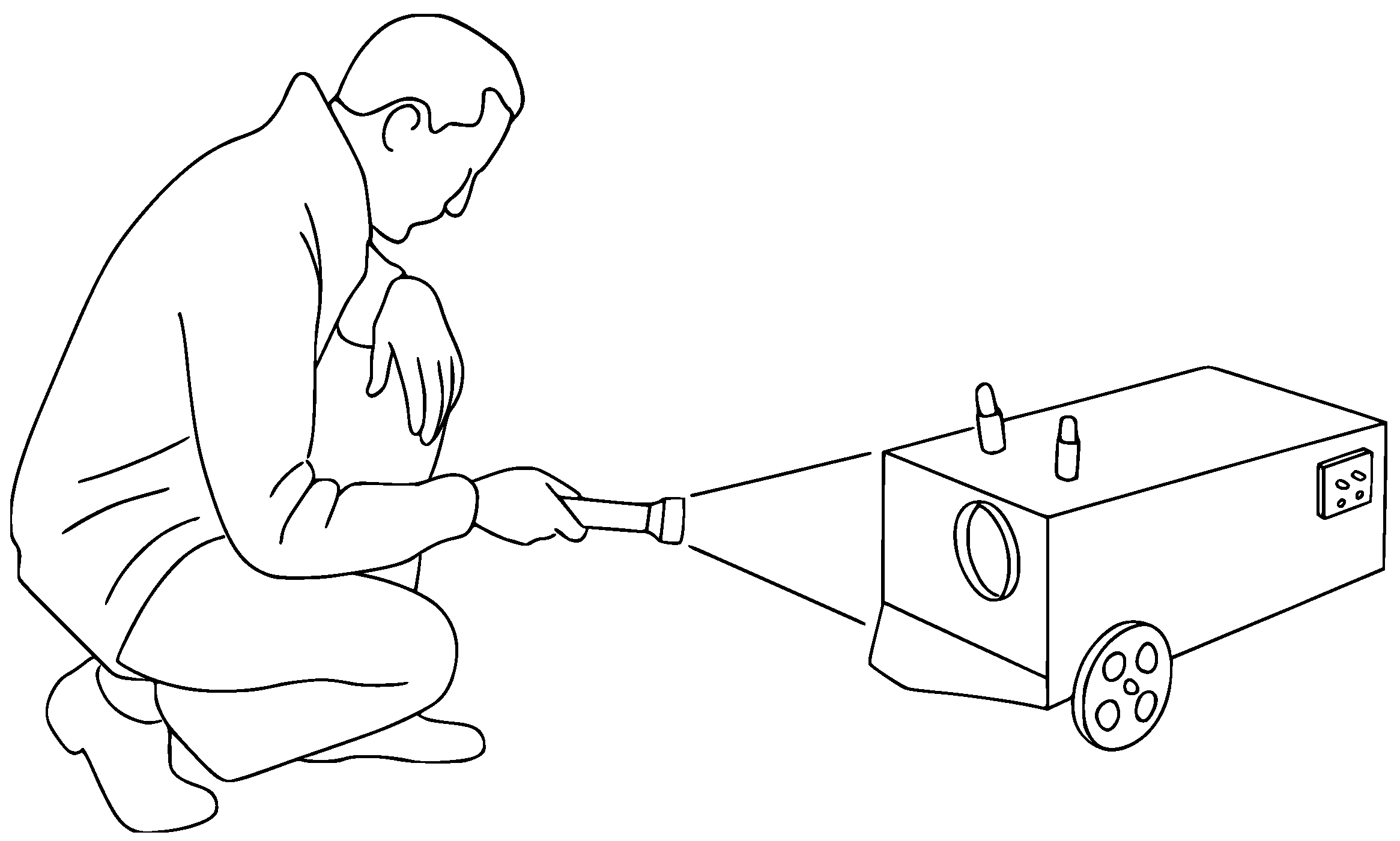
The development and use of UGVs began in the late 19th and early 20th centuries. One of the earliest records of autonomous unmanned ground vehicles dates back to 1912, that is, Hammond and Miessner’s ”Electric Dog” [41], which is a tricycle capable of following a light source, as shown in Figure 2. The UGV mentioned before was designed in 1912, but the article shown in Figure 2 was written in 1919.
The first comprehensive adopter of these vehicles was the military industry. Heverett documented the use of these systems during the two world wars in his book “Unmanned Systems of World Wars I and II” [43]. At the time, the attention of various governments was drawn to the development of these systems due to their potential applications. In particular, these vehicles were used to carry explosive charges, which were then detonated upon reaching the target. For example, the French Army developed the Aubriot-Gabet Torpille Electrique, an electric vehicle controlled by acting on the track clutch, in 1916 [44]. In 1918, Elmer Wickersham developed the Wickersham Land Torpedo [45]. In 1940, Germany focused on further developing these systems for military purposes. The purpose was to design a vehicle for detonating explosive charges in the enemy camp. The vehicle developed was named Goliath [46] and was controlled by a joystick connected to the vehicle via three cables: two for movement control and one for triggering the device. In the same years, the Soviet Union also developed tanks controlled at distances between 500 and 1500 m [47].
Starting from the 1950s, UGVs began to find applications outside the military. The agricultural field was one of the first to develop in this respect. In particular, remote control systems for operating a tractor were developed. Two significant milestones were achieved between 1955 and 1958 in England [48]. In 1955, a hydraulically operated tractor was controlled remotely via radio. There was also a safety device on that system consisting of a spring-loaded mechanism that cut off the fuel in the event of a malfunction. In 1957, a British farmer extended this approach by using a transmitter to control a second identical radio-controlled tractor. This tractor, equipped with a receiver and a relay-controlled hydraulic system, replicated the operations of the first, allowing a single operator to operate both vehicles simultaneously. In 1958, another prototype was designed to track an electric pilot wire placed on the ground automatically. Two coils detected the signal, activating a hydraulic system that acted on the steering wheel to keep the tractor aligned with the cable.
Apart from advancements in agricultural fields, unmanned ground vehicles have become the subject of study in numerous university laboratories and are used in various application areas [49,50,51]. The Shakey, developed in 1960, was one of the first autonomous vehicles presented in the scientific literature [52,53,54]. Moreover, it was the first robot to demonstrate good autonomous handling and manipulation capabilities. In 1969, Nilsson published an article entitled ”A Mobius Automation: An Application of Artificial Intelligence Techniques” which describes the application of artificial intelligence techniques for developing mobile robotic systems [55]. The purpose was to create programs for processing sensor data and planning the implementation actions necessary to move the UGV. In 1970, the Wheelbarrow was developed for use in explosive ordnance disposal operations and was adopted by the British Army [56]. Yerazunis published a paper that discusses the problem of controlling a UGV in 1978 [57,58]. The purpose was to develop a vehicle intended for space exploration that could select the most direct route and conserve energy. In the early 1980s, the topic of mobile robots was explored in a new DARPA Autonomous Land Vehicle (ALV) project. The project aimed to develop autonomous land vehicles capable of moving in complex environments. Great emphasis was placed on technological development to improve the performance of UGVs [59,60,61]. Between 1990 and 2000, several prototypes emerged for applications in different agricultural areas [62,63,64], logistics, and transportation.
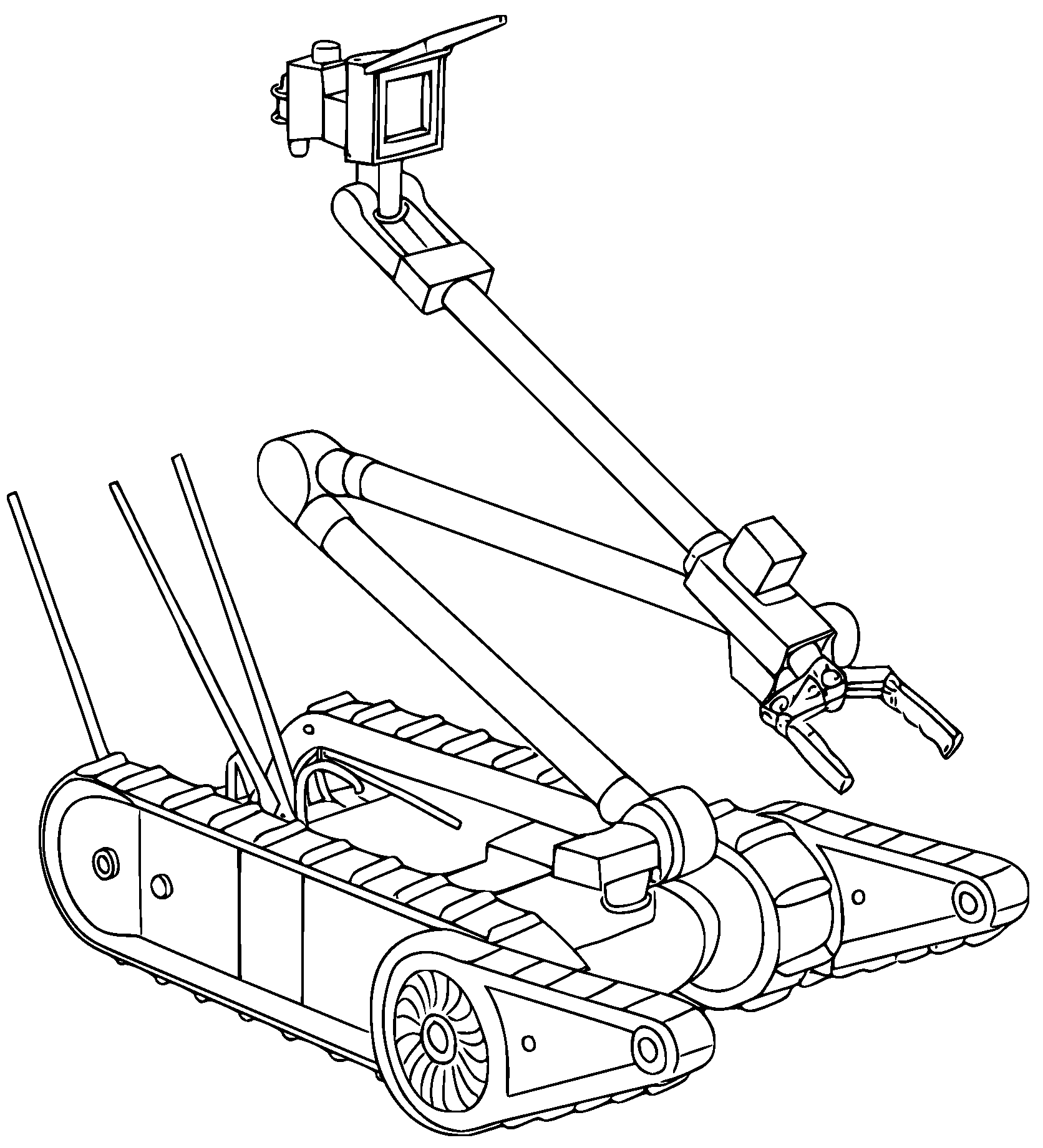
In the 2000s, the iRobot company developed a robot named PackBot, shown in Figure 3. In 2001, it was used to search through rubble at the World Trade Center. Also, in the 2000s, Foster-Miller developed a UGV (TALON) designed primarily for explosive ordnance clearance. Until 2004, more than three thousand units were deployed worldwide, participating in more than twenty thousand missions, including entering trapped caves, searching for improvised explosive devices (IEDs), and reconnaissance in combat zones [65].
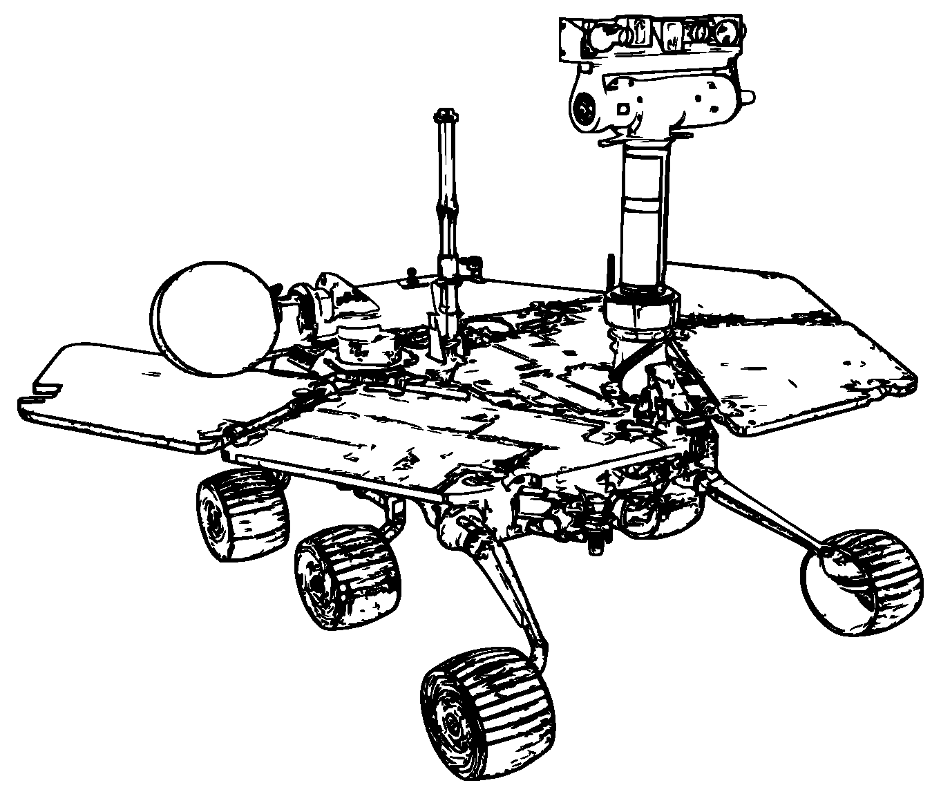
It is observed that there has been a significant increase in UGVs since 2000. In particular, the miniaturization of electronic components, improved sensors, and increased computational power have significantly accelerated the development of UGVs in recent decades. An example of the miniaturization of electronic components is the mobile robot developed by the Jet Propulsion Lab. In 2004, NASA sent two rovers to Mars to explore the planet. In [67], one of these designs for the rovers is shown with particular detail on the suspension system and wheels. The architecture of the rover is called a rocker-bogie because the six wheels with which the rover is equipped are connected to the central body. Figure 4 shows the Opportunity rover sent to Mars.
In this vein, the paper ”Exploration Rover Concepts and Development Challenges” is of considerable interest, published in 2005 [69]. The authors provided an overview of technological obstacles and solutions for rover development. Another project of significant interest was the TerraMax, a fully autonomous vehicle developed by the Oshkosh Truck Corporation in collaboration with Rockwell Collins and the University of Parma [70]. The purpose was to create a platform that enables military vehicles to become autonomous. TerraMax-equipped cars participated in the 2004 and 2005 DARPA challenges and the 2007 DARPA Urban Challenge [71]. During this period, the UGV Ripsaw was also developed [72]. Developed by Howe & Howe Technologies, the Ripsaw MS1 was renowned for its speed, agility, and versatility in military and security applications. One of the main advantages of that UGV was its impressive speed of 80 km per hour, coupled with an empty weight of approximately 4500 kg [73].
To conclude, between 2005 and 2024, Unmanned Ground Vehicles (UGVs) experienced significant transformation, primarily driven by technological advancements. Innovations in artificial intelligence and sensors have led to the development of increasingly autonomous and versatile platforms that can operate effectively in complex, multi-sector environments [74,75].

3. Systematic Literature Review of Modern UGVs

3.1. Methodology Overview

Literature reviews are among the most critical pieces of research needed at the beginning of every scientific research process, as they compile previous scientific knowledge in a specific field. These reviews can be carried out with two main approaches, namely the narrative method and the systematic literature review method. The narrative method becomes an efficient approach when there are limited sources available, due to the narrowing of the research topic or the limited number of documents that can be accessed. In this case, these sources can be reviewed to reveal the historical development process of the subject of interest. Thus, since it can effectively convey the historical development of a research field, this method can be valuable when necessary. However, if numerous published studies are available in a specific field of interest within a short period, the effectiveness of this approach is debatable. Moreover, if this method is adopted, factors such as bias, subjectivity, and personal experience have the potential to affect the objectivity of the study negatively. In contrast to the limitations of the narrative method mentioned above, the systematic literature review method has the advantage of being able to review a considerable number of studies published within a specific period on a particular topic, employing scientific analysis methods. Moreover, in virtue of the standardized and systematized approach adopted in this type of literature review process, it can produce reproducible, objective, and transparent results.
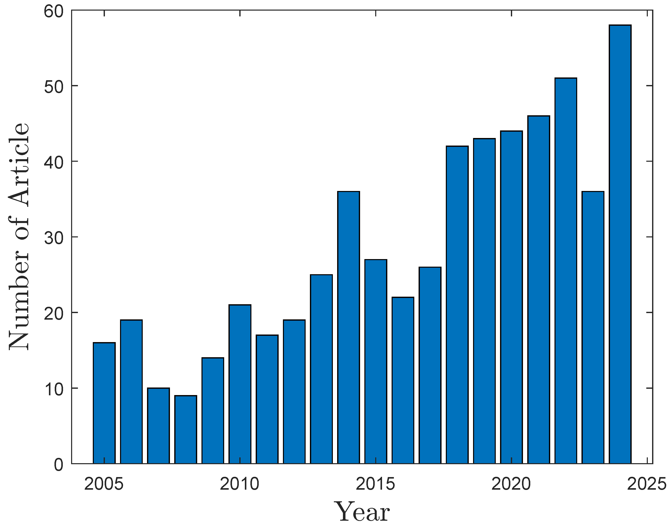
It was observed that the number of studies on unmanned ground vehicles up to 2005 was sufficient for presenting the historical framework using the narrative method. For this reason, in Section 2, studies on the development of unmanned ground vehicles until 2005 were presented using the narrative method. However, as can be seen from Figure 5, due to the tremendous pace of development in various and ever-evolving engineering disciplines such as mechanics, electronics, control, energy management, and artificial intelligence that constitute unmanned ground vehicles, the number of scientific publications produced on UGVs has increased rapidly since 2005.
For this reason, the literature review on the development of unmanned ground vehicles between 2005 and 2024 is carried out in this section using the systematic literature review approach.

3.2. Implementation of the Systematic Literature Review Method

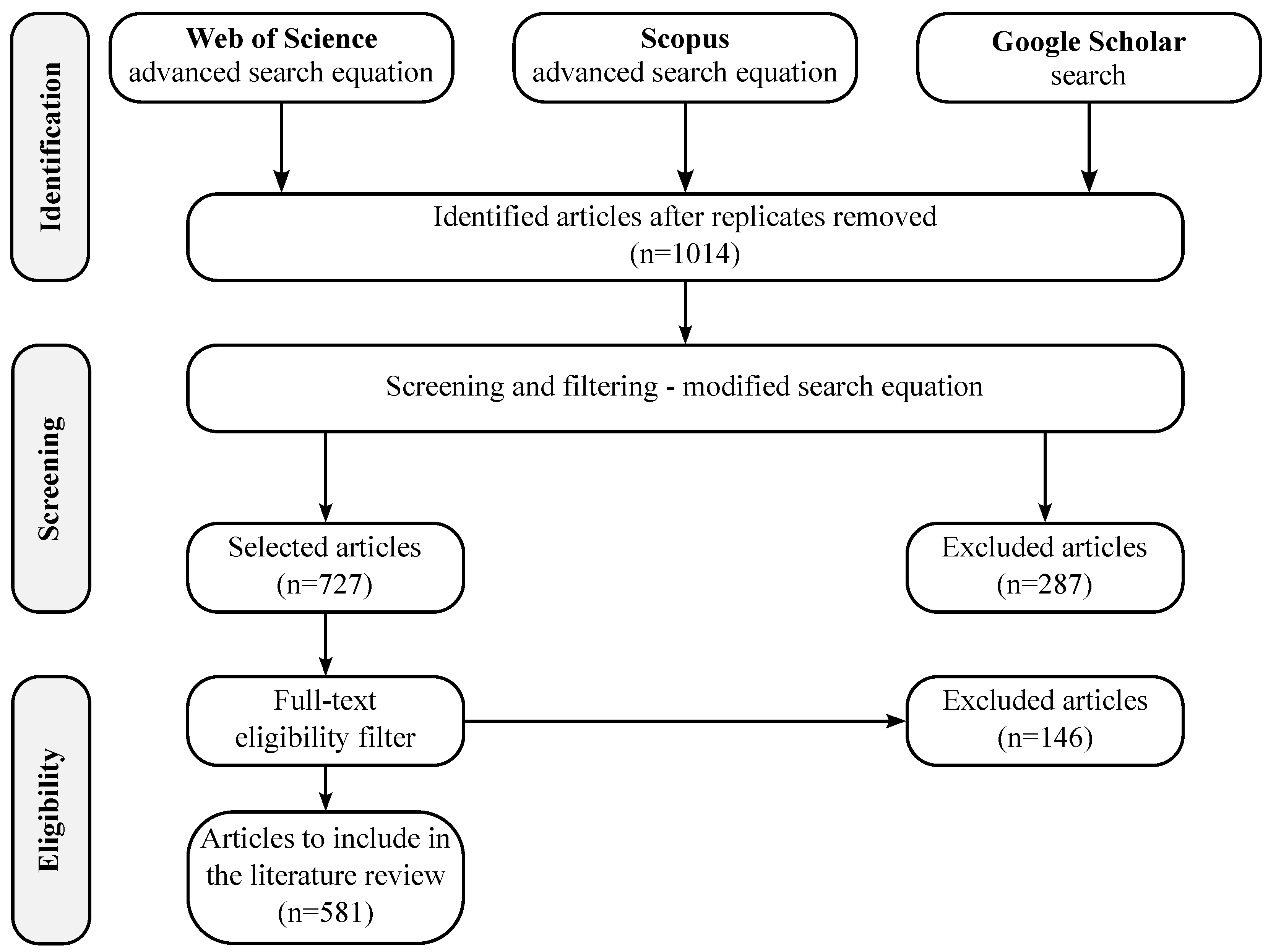
The PRISMA (Preferred Reporting Items for Systematic Reviews and Meta-Analyses) standard procedure is used in the systematic literature review procedure employed in this investigation [76]. As shown in Figure 6, the first step of the systematic literature review is to identify the English-written studies on the topic of interest in the relevant time period.
In this context, an advanced search equation was created to perform an objective database search in the Web of Science and Scopus databases. In addition, a complementary search was also conducted in Google Scholar. The following advanced search equation was used in the database search:
(( ugv OR ’unmanned ground vehicle’ ) AND ( ( ’terrain interaction’
OR ( ’traction system’ ) OR ( ’path planning’ ) OR ( ’control system’ ) )))
The keywords used in this investigation for the advanced search prompt mentioned above were identified through a historical review. Afterward, the duplicates in the found sources were eliminated. In the next step, screening, the target source set was narrowed down by examining the contents of the identified studies. Then, the narrowed-down source set was filtered again in terms of eligibility, and the final source set to be added to the literature review was obtained. As a result of these steps, 581 studies were included in the bibliographic analysis.

3.3. Bibliographic Analysis

The Bibliometrix tool developed in R software was used for the bibliometric analysis carried out in this study [77]. Table 1 presents the main information about the reviewed documents.
Table 2 also shows the general information on the document types and their content. As can be seen from Table 2, in addition to articles, there are also many studies presented at conferences on this subject.
Table 3 presents the general information on the authors and authors’ collaborations. As can be seen from Table 3, the majority of the studies presented on this subject are the result of collaborations between authors.
In addition, the first ten most cited sources are listed in Table 4.
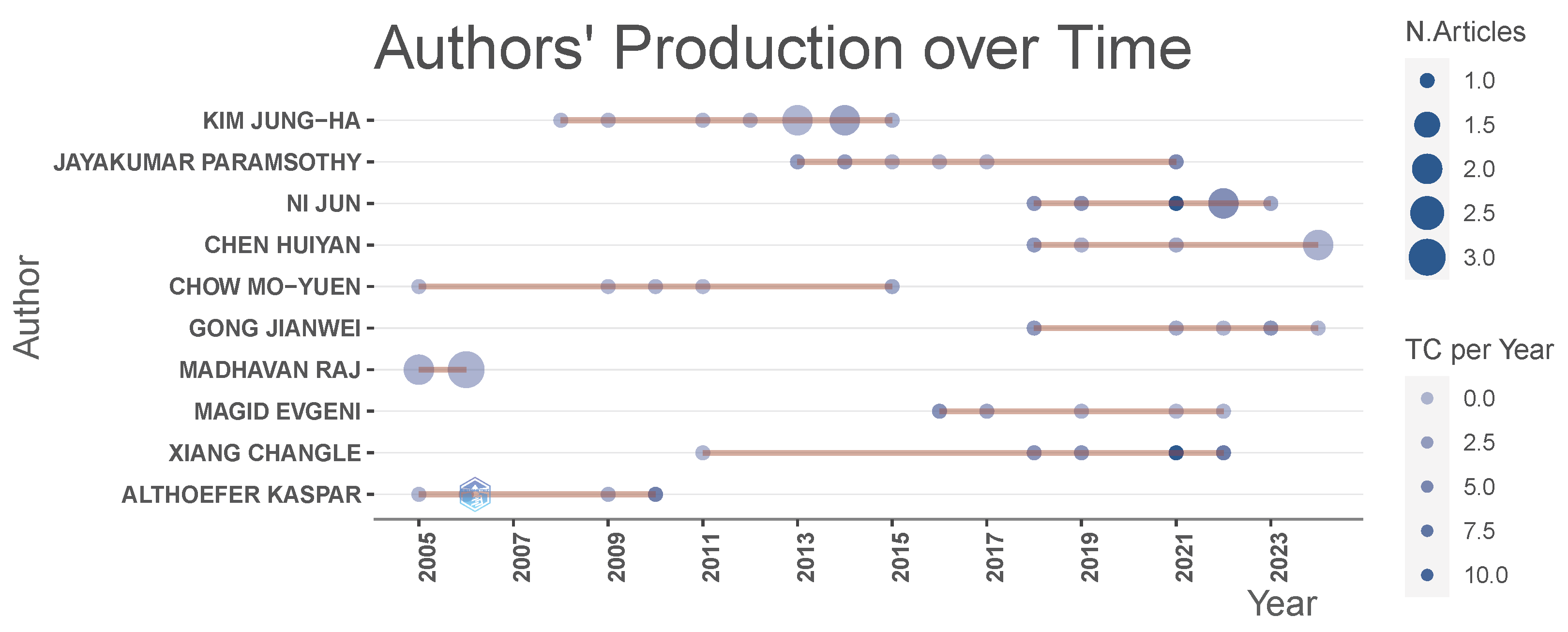
The research output of the top 10 authors between 2005 and 2024 is illustrated in Figure 7. In Figure 7, the size of the bubble refers to the number of articles published. The color intensity also indicates the total number of citations per year. The order of authors is established from top to bottom according to relevance. The number of publications is taken as the basis for determining the author’s relevance.
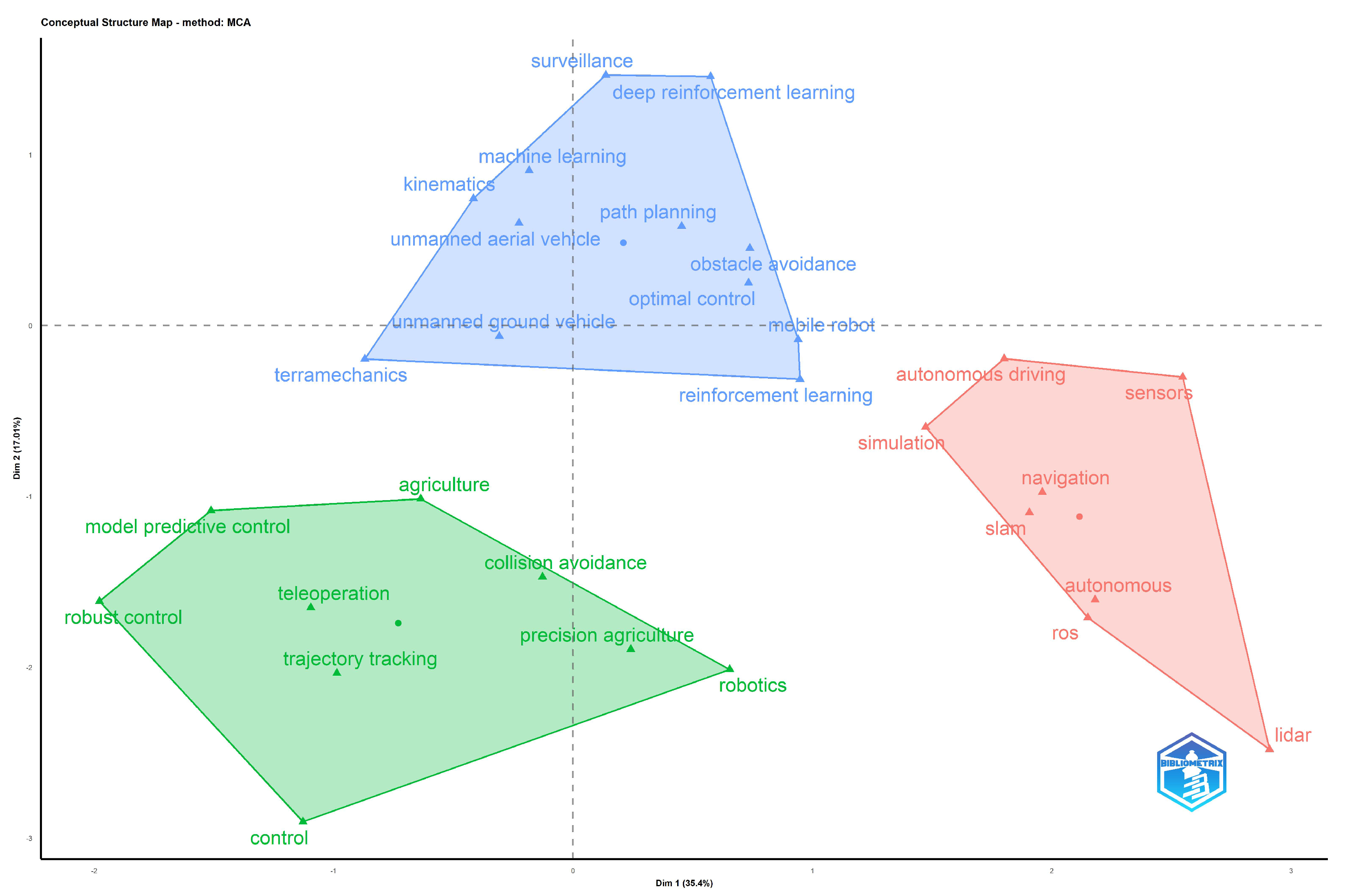
Additionally, a conceptual map indicating the main concepts of unmanned ground vehicles is presented in Figure 8. For this purpose, a factorial analysis is performed by utilizing the Multiple Correspondence Analysis (MCA) method with the authors’ keywords of the collection of selected articles.
In Figure 8, the origin of the axis indicates the center of the research field [77,87,88]. The variation of the data obtained from dimensional reduction is respectively 35.4% and 17.01% for the Dim 1 and Dim 2 axes. As can be seen, three clusters, colored in blue, red, and green, are identified by the K-means algorithm. The blue cluster encompasses topics related to the fundamental design principles of unmanned ground vehicles, including soil-wheel interaction and kinematics, as well as collaboration with unmanned aerial vehicles for path planning, obstacle avoidance, and machine learning. The red cluster focuses on autonomous navigation and mapping, which is closely related to Simultaneous Localization and Mapping (SLAM) and Laser Imaging Detection and Ranging (LIDAR) applications. The green cluster encompasses control subjects for trajectory tracking, teleoperation, and agricultural applications.
Figure 9 illustrates the author collaboration network. In generating this network, the Kamada-Kawai network layout was used with the Salton normalization index. Additionally, the Louvain algorithm was used for clustering. It should be noted that the edge sizes are proportional to the number of standard works between the connecting authors. Moreover, the co-authorships are illustrated using colors.
Finally, Figure 9 demonstrates that Jun Ni, Paramsothy Jayakumar, Huiyan Chen, and Mo-Yuen Chow are the most influential authors in the present research field between 2005 and 2024.

4. Components of Modern Autonomous UGVs

4.1. Comparative Analysis of Tracked and Wheeled UGV Locomotion Mechanisms

This section complements the aforementioned classification by analyzing all the other features that give the single UGV its identity, making it a unique vehicle suitable for moving into specific areas often unreachable by humans. UGVs are used in various applications and can be equipped with either wheels or tracks. The choice between the two depends on the specific application. Another way to classify UGVs is based on their steering configuration. In particular, the literature distinguishes between steered and fixed systems. Several types of market-available UGVs can be classified based on their weight, locomotion, power supply system, hardware, navigation, and control systems. In terms of weight, UGVs can be distinguished into four groups: Featherweight Robotic Vehicles (vehicles that weigh less than 5 kg), Man Portable UGVs (vehicles that weigh between 5 and 50 kg), Medium Weight UGVs (vehicles that weigh between 50 and 500 kg), and Heavy Weight UGVs (vehicles that weigh above 500 kg) [89]. A comparative analysis of tracked and wheeled locomotion systems for UGVs is presented below.
In fixed-wheel systems, the wheels are mounted in a fixed orientation and cannot rotate around a vertical axis to steer. Changes in direction are achieved by varying the rotational speed of the wheels on either side of the vehicle. This approach is commonly used in tracked vehicles or UGVs with fixed wheels, which offer high maneuverability, especially in unstructured environments. Steered wheel systems, on the other hand, feature wheels that can be rotated around a vertical axis to change the direction of the vehicle actively. These systems can utilize Ackermann steering, four-wheel steering, or other configurations that enable smoother and more efficient directional control, particularly at high speeds or on even terrain. In [90], a comparison is made between two steering geometries: Ackermann and skid-steering. The comparison evaluates the steering tension between the two designs.
Skid-steer UGVs are vehicles where opposite wheels rotate at different speeds while the wheels on the same side rotate at the same angular velocity [91]. This technique is used for wheeled and tracked vehicles and is primarily employed in the military. For example, an eight-wheeled UGV exploiting the skid-steer strategy is described in [92]. From the control point of view, the skid-steering system is more straightforward, as it only requires wheel speed control, while the steer wheels need control of both speed and steering angle. In [93], the dynamics and control of skid-steered vehicles are analyzed, showing that on high-friction terrain, maneuvering becomes difficult. Generally, four-wheel skid-steer vehicles are suitable for light vehicles, while tracked or multi-wheel coaxial systems are used for heavier applications. In [94], a heavy-weight (590 kg) skid-steered UGV was examined on different surfaces, such as concrete and snowy ground, to analyze the odometry patterns employed in motion control and path planning. On concrete, the robot operated on a dry surface with a high coefficient of friction and stiffness, where skid-steering motion was mainly caused by wheel deformation, influenced by the stick-slip phenomenon, which introduced unmodeled noise. On the snowy ground, on the other hand, with a low coefficient of friction and low stiffness, the motion was induced by ground deformation, with the unevenness of the surface introducing additional noise, especially at high speeds. Zhang et al. [95] compared Ackermann steering and skid-steer. In the first configuration, the turning radius is constrained by the wheelbase and steering angle. With the skid-steer strategy, the vehicle can perform zero-radius turns.
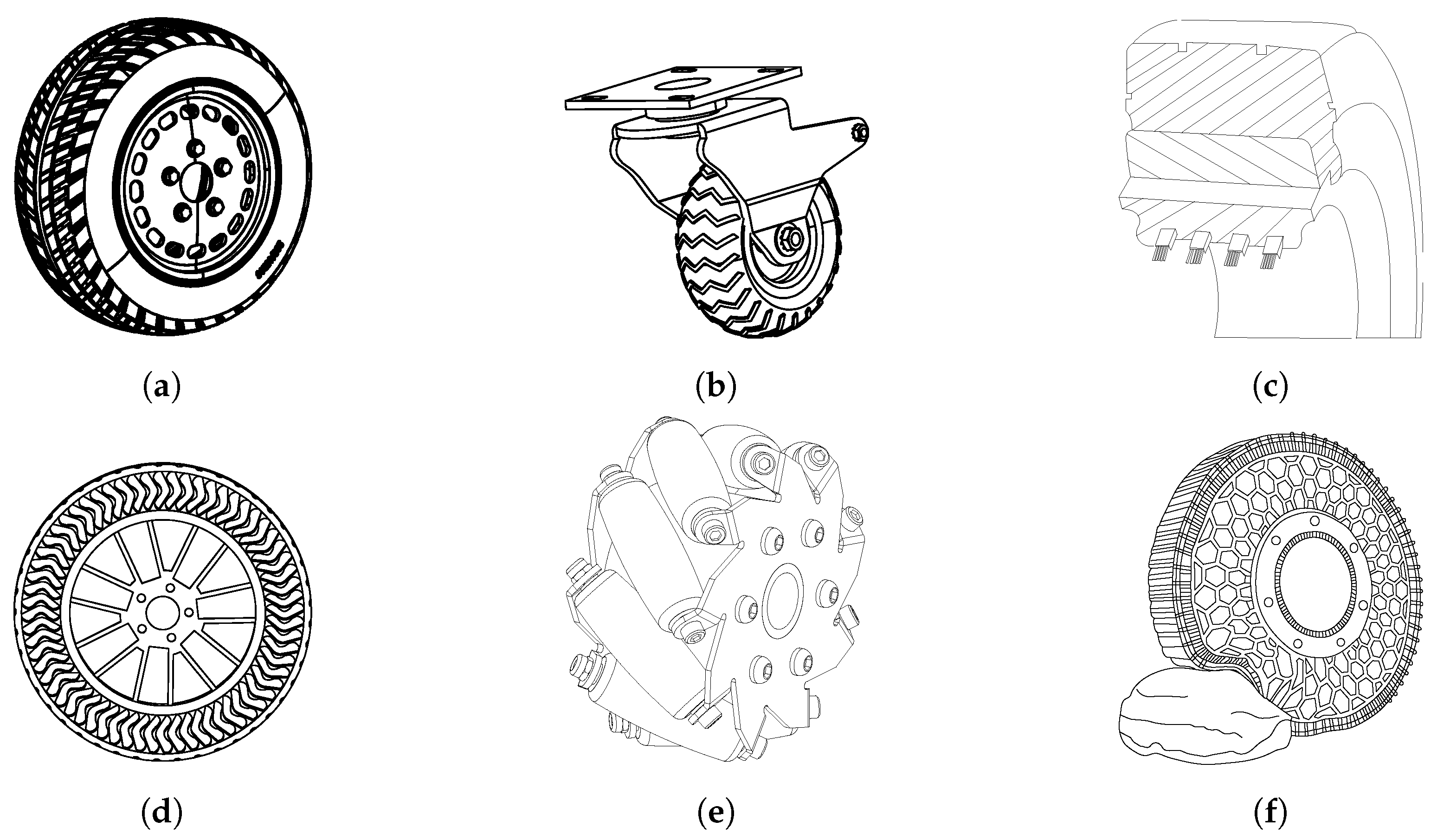
The choice of wheel type has a significant impact on the vehicle’s performance in terms of mobility, grip, and its ability to adapt to various types of terrain. In the literature and over the years, various kinds of wheels have been developed for use in different scenarios. At its simplest, a UGV can be designed using conventional wheels. Figure 10 is a synthetic graphical representation of all the different types of wheels analyzed in this study.
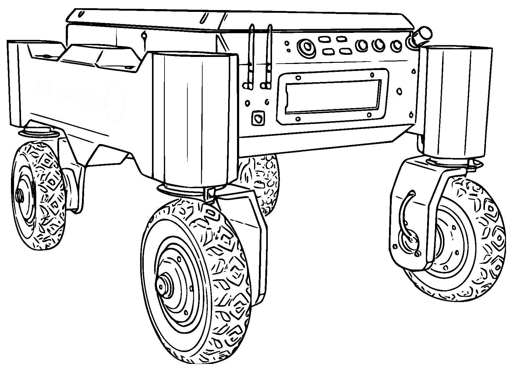
More specifically, a traditional wheel is defined as one such as shown in Figure 10a. This wheel type may have a different tread shape. For example, it could be notched for off-road applications. Generally, these are used to have high traction in muddy, sandy, or snowy environments [97]. A particular type of wheel used in mobile robots is the free caster wheel shown in Figure 10b. This is a passive wheel, in that it has no motor for either traction or steering. It is free to rotate around a pivot and adapts to the direction of movement imposed by the driving wheels. Usually, these wheels are suitable for movement on flat surfaces and are not ideal for rough terrain [98]. On agricultural land, the active caster wheel is used. In these cases, there are two motors: one controls steering and the other provides traction. An example is the 4WD eXplorer robot shown in Figure 11.
Solid tire wheels are wheels in which the tire does not contain compressed air. They require low maintenance and high strength. They are suitable for use in hostile environments with high shear risk. Steel wires on the inside are used to provide a better grip on the rim. They are often made of more than one material so that their mechanical properties are changed. Figure 10c shows a tire consisting of two different materials and four steel wires. This type of wheel is used for vehicles that must carry high loads.
The airless tire, also called non-pneumatic tire, is a new mechanical system that replaces the classic tire [100]. An example is shown in Figure 10d. It consists of a rigid hub and a tread band connected to the hub by flexible spokes. It is a system that is able to function even if it is punctured [101]. Airless tires can have complex geometry, including structural discontinuities, and are designed to experience large deformations to be able to traverse uneven terrains [100,102]. Therefore, the design and analysis of this kind of locomotion system requires advanced tools capable of correctly handling finite rotations and large deformations at the same time, like the multibody system approach to vehicle dynamics and the use of the Floating Frame of Reference Formulation (FFRF) combined with the Absolute Nodal Coordinate Formulation (ANCF) [100,103,104,105,106,107].
Another type of wheel used in mobile robots is the Mecanum wheel shown in Figure 10e. The wheel consists of rigid rollers inclined at a 45-degree angle to the wheel axis. This particular design allows the wheel to generate forces both along the direction of rotation and laterally. Depending on the rotations of the vehicle wheels, different types of handling are possible. Typically, these wheels are suitable on smooth surfaces with no high friction [108,109].
A wheel of considerable interest developed recently is the morphing wheel with variable stiffness [96], shown in Figure 10f. The need to create such a wheel arises from the fact that the standard wheel cannot overcome significant obstacles. By using an adjustable stiffness wheel, this vehicle can take a stiff shape on flat terrain and a soft shape to overcome obstacles. The system is controlled through spokes that connect the chain structure of the wheel to the central hub. The wheel has the characteristics of a standard wheel when the spoke tension increases, while it becomes deformable when the spoke tension decreases. A similar morphing concept has been recently developed in the work of Park et al. [110], who proposed an optimized shape-shifting wheel to maintain consistent performance across different ground conditions and driving speeds.
In challenging contexts, tracked UGVs are generally employed. The ability of these vehicles to operate in rough terrain is due to the large contact area between the track and the surface, providing better traction and stability during maneuvers [111]. Tracked systems are widely used in uneven environments. They feature good stability, a simple control and handling system, and exert low pressure on the ground.
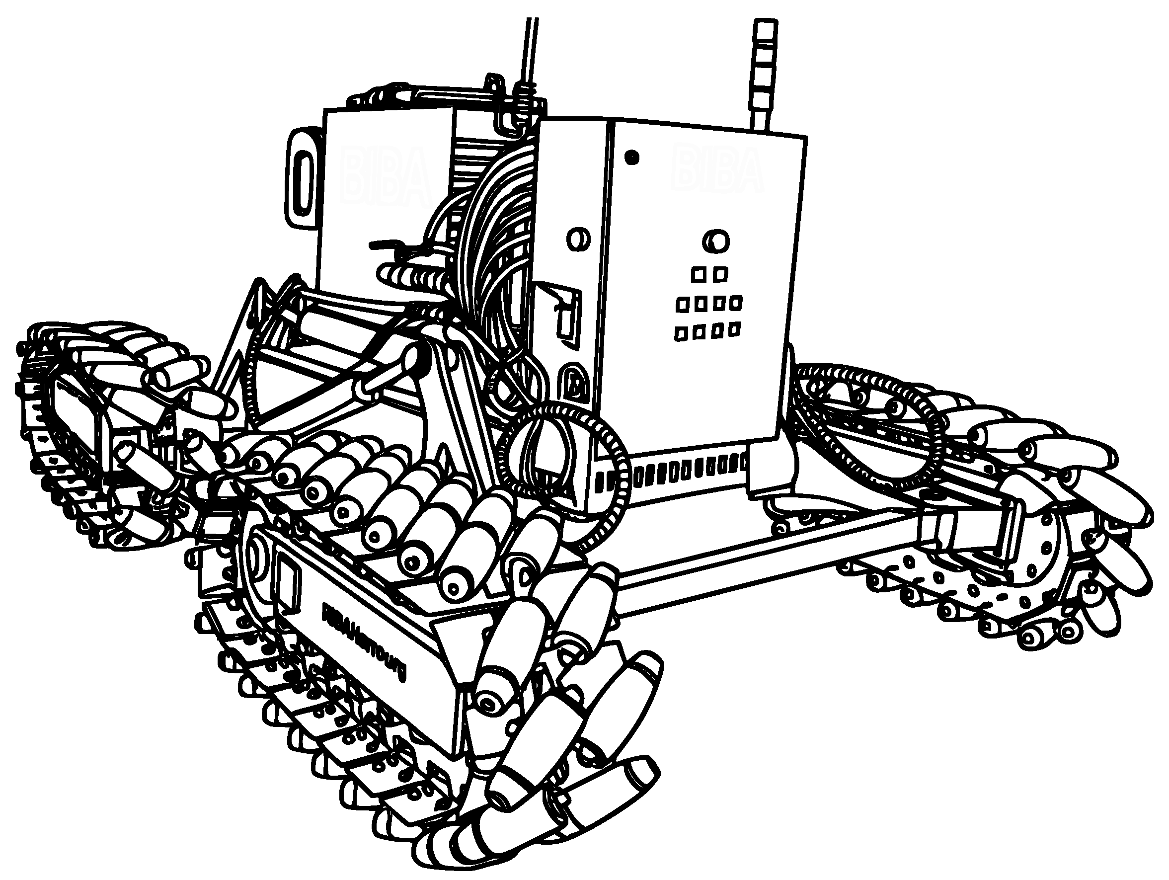
There are different types of crawler systems, which can be classified according to the track type (flexible, rigid, and omnidirectional) [112]. Omnidirectional systems are widely used in robotics. These systems allow the robot to move with high maneuverability but can only be used on smooth, clean surfaces. In [113], a crawler system based on the operation of the Mecanum wheel is presented [114]. It is possible to move in any direction using this system and rotating the tracks differently. Figure 12 shows an example of an omnidirectional robot.
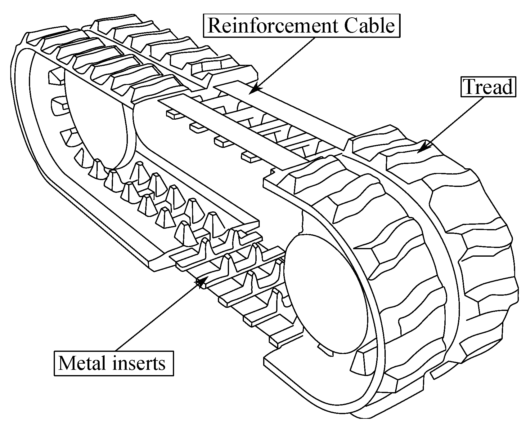
The most popular solution for tracked vehicles is to use a flexible or rigid track system. Flexible tracks are characterized by metal inserts, reinforcing cables, and the continuous rubber tread [116,117]. The metal inserts, which are placed at regular intervals defined by the pitch, are essential to ensure contact between the track and the undercarriage wheels. Steel or fabric cables improve tensile strength. These cables are sized according to diameter and number of windings. Figure 13 shows an example of a flexible track.
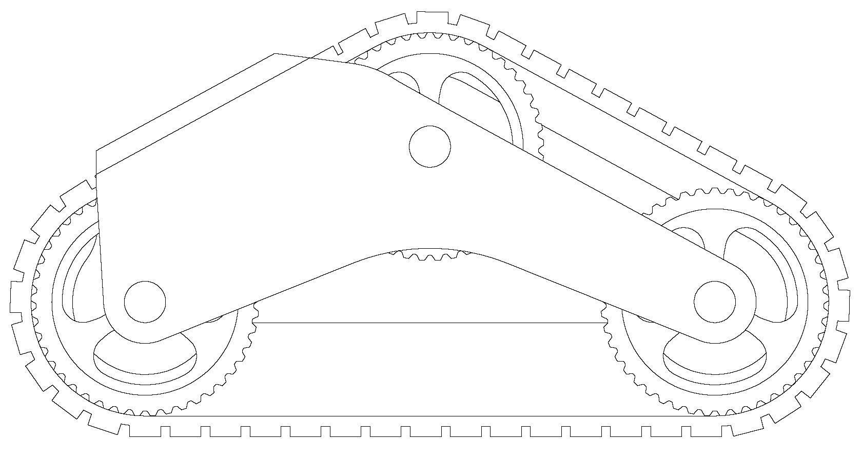
In addition to their materials, track systems can also be grouped based on rack configuration and wheel positioning. A typical horizontal track has good terrain adaptability but has high friction resistance. This results in high energy consumption. To overcome this issue, triangular tracks have been developed and mounted in place of wheels. Triangular tracks, such as those in Figure 14, have the advantages of wheel traction and the stability typical of the track. It allows the vehicle to move with agility over different types of terrain.
Liu et al. studied in detail the advantages of adopting triangular tracks in a combine harvester [118]. The triangular design enables more even load distribution, enhancing stability on uneven or muddy terrain. It also provides a smaller turning radius, which is helpful in fields with limited space. An integrated reassemblable wheel-track mechanism is presented in [26]. The mechanism allows the vehicle to switch between wheel and triangular track modes by the movement of a deformation mechanism. In this way, the system can choose the best traction according to the terrain characteristics.
Selecting a different traction system is mainly influenced by the type of soil [119]. These are classified according to several aspects such as composition, cohesiveness, and grain size. Soils can be classified into cohesive, frictional, semi-cohesive, rocky, organic, and mixed soils [120]. Cohesive soils are defined as soils characterized by the presence of very fine particles. They are characterized by high deformability and exhibit plastic behavior under load. On the other hand, frictional soils are composed of larger particles, such as sand or gravel. They exhibit low deformability because the particles that make up the soil tend to slip rather than deform plastically. Semi-cohesive soils lie between cohesive and frictional soils. Organic soils, on the other hand, are characterized by very low tensile strength and can lead to localized sinking and uneven deformation.
In this paper, it is not possible to thoroughly examine all terra-mechanical models, but some key parameters are provided below to best interpret the treatment [121]. A key parameter in the equations describing soil behavior under load is the shear stress-strain relationship, which is identified by the parameter k. It measures the resistance of the soil to deformation under shear forces, such as those generated by contact between a wheel or track and the ground. It represents a key parameter in the design and simulation of off-road vehicle performance, influencing the choice between wheels and tracks for specific types of terrain. A high value of k indicates that the soil can resist larger deformations before reaching the maximum stress [122]. This is observed, for example, in more compact or cohesive soils. A low value of k suggests that maximum stress is reached quickly with minor deformation, which is typical of less cohesive soils such as sand or gravel.
Having finished the overview of the different wheel and track configurations, it is essential in this subsection to provide the reader with a comparison of the standard wheel and horizontal track, representative of the most commonly used solutions. The goal is to highlight the main trade-offs and distinctive performance characteristics of each system. To fully understand the performance and differences between the two traction systems, it is necessary to study the vehicle-ground interaction [123].
Wong et al. made a comparison of a multiaxial wheeled vehicle versus a tracked vehicle [85]. The traction of wheeled vehicles is lower than that of tracked vehicles. This is related to the ground contact area, which is less in the case of wheeled vehicles. Wheeled vehicles approach the performance of tracked vehicles on sandy and rocky soils. In experiments, it has been observed that the pressure is distributed similarly to wheeled vehicles in hard soils. Using this logic, it is also possible to use a model for tires for tracked vehicles as done by Zhang et al. [124]. From a computational point of view, it is possible to study the interaction with the terrain with different approaches. The terrain can be represented with a set of particles according to the discrete element method [125,126]. Furthermore, a finite element model can be utilized by partitioning the soil into distinct volumes, each with its unique mechanical properties.
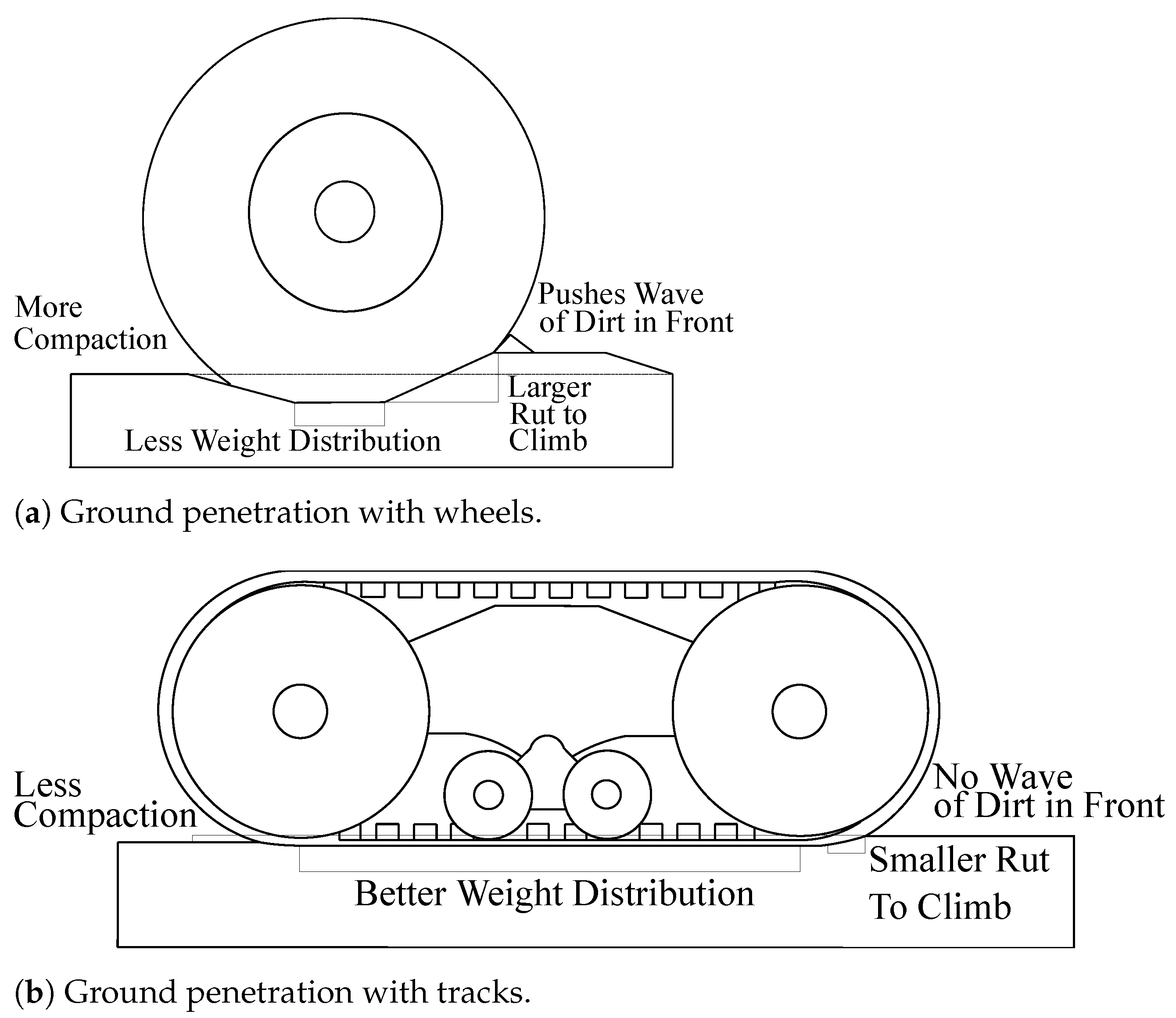
In [127], a comparison was made between a wheeled cart and a tracked cart. Ground contact is studied using an Integrated Soil Contact Model [128,129,130]. The main difference that emerged from the simulations is the load distribution. Tracked trucks are better suited for traversing soft and uneven terrain due to the larger contact area. This reduces sinking. Wheeled trolleys are more efficient on hard, flat terrain. In soft terrain, on the other hand, they are more prone to sinking. To clearly explain the difference between wheel and track, a summary image of the discussed and researched points is proposed in Figure 15.
By closely observing Figure 15a,b, it is possible to have a visual comparison between tracks and wheels. In tracked systems, there is better weight distribution, and the pressure exerted on the ground is also reduced, thereby reducing soil compaction [131]. In the case of wheels, the contact surface is smaller, so the wheel exerts more pressure on the soil. In this case, the problem of soil compaction is greater. In addition, the wheels tend to push waves of soil in the forward direction. Additionally, these accumulations can impede the progress of the vehicle. The greater pressure exerted by the wheels leaves more pronounced ruts, making progression more difficult, especially on soils that deform plastically.

4.2. Power Supply Systems for UGVs

Power supply is a crucial aspect of the operation of unmanned ground vehicles, directly affecting range, performance, and operational capabilities. The most common power sources for UGVs are batteries combined with electric motors, particularly in small and medium-sized platforms.
Several hybrid solutions have been proposed in the literature to improve the energy efficiency of these vehicles. For example, a system was presented in [132], in which an internal combustion engine drives an electric generator, while electric motors provide the vehicle motion. This configuration reduces power losses associated with mechanical transmission, as each wheel is individually driven by In-Wheel Motors (IWM), thereby improving the overall efficiency of the system.
Using IWM in off-road vehicles poses significant challenges. One of the main problems is managing power distribution between the drive wheels, which are no longer connected by a conventional transmission system. Without an appropriate control strategy, there is a risk of increasing power losses due to slip, reducing the overall energy efficiency of the vehicle [133]. An alternative, cutting-edge hybrid solution is the electric motor coupled with fuel cells [134,135].
Another interesting hybrid power solution is described in [136], where a system based on a polymer membrane fuel cell (PEMFC) serves as the primary power source. The system also includes batteries and supercapacitors to store energy reversibly. The goal of this configuration is to optimize real-time power distribution between the fuel cell and storage devices, minimizing hydrogen consumption and maximizing energy efficiency during dynamic driving cycle loads.
A practical example of this technology is provided in [137], which presents a system consisting of six lithium-ion polymer (LiPo) cells connected in series and a 200-watt proton-exchange membrane (PEM) fuel cell. In this case, the fuel cell is connected in parallel with the batteries without any restriction on charging, allowing for longer system lifetime and improved operational reliability.
Barreras et al. developed an all-wheel-drive (AWD) multipurpose electric vehicle with a hybrid powertrain based on PEM fuel cells and lead-acid batteries [138]. This vehicle uses two chassis connected by a universal joint and a propulsion system that combines fuel cells and batteries, offering good versatility and performance in complex environments.
The efficiency of a series hybrid UGV, consisting of electric motors, batteries, and a diesel generator, was analyzed in [139]. In this system, the battery serves as an energy buffer, while the diesel generator acts as a backup power supply, providing a greater range in high-load situations. In [140], combining eco-driving optimization with efficient energy management, a co-optimization strategy for hybrid unmanned electric crawler vehicles (HETVs) was proposed. Based on a hierarchical control framework, the plan aims to ensure accurate path tracking and optimal energy management simultaneously.
Finally, an advanced energy management strategy based on Deep Reinforcement Learning was proposed in [141]. This approach enables the optimization of power distribution according to road characteristics, thereby further improving vehicle efficiency under varying driving conditions.
In summary, Table 5 presents an overview of the power supply systems used in the unmanned ground vehicles reviewed in this study.

4.3. Hardware Systems

In recent years, advancements in hardware have played a crucial role in the development and deployment of unmanned ground vehicles. These autonomous systems, used in a wide range of applications, depend on a combination of highly specialized hardware components to ensure optimal performance in dynamic and complex environments. This subsection provides an overview of the major hardware components that comprise UGVs.
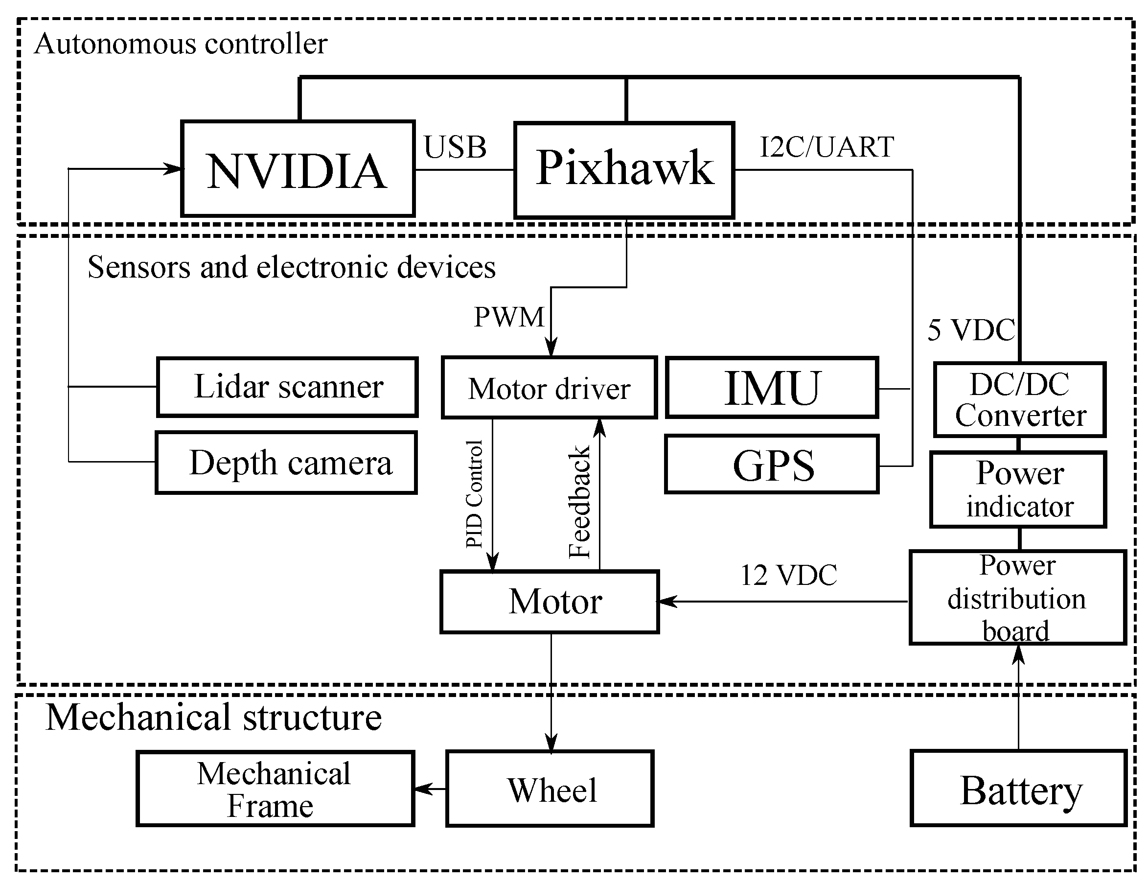
A robotic platform for teaching and research purposes is presented in [142]. The system has two configurations: a minimal configuration and a more extensive configuration. The two systems share the same central controller. The primary difference between the two configurations lies in the use of different NVIDIA-embedded computers: the minimal configuration utilizes the Jetson Nano, while the extended configuration employs the Jetson TX2. The NVIDIA Jetson Nano and NVIDIA Jetson TX2 modules are designed for applications in the fields of artificial intelligence and robotics. Still, they have substantial differences in their capabilities and technical specifications. The Jetson Nano represents a more affordable solution suitable for low-power projects. Equipped with a 128-core NVIDIA Maxwell graphical processing unit (GPU) and 4 gigabytes (GB) of DDR4 random access memory (RAM), it offers adequate performance for entry-level visual processing and machine learning applications. Its power efficiency makes it ideal for scenarios where power resources are limited. On the other hand, the Jetson TX2 is designed to handle more demanding applications. With a 256-core NVIDIA Pascal GPU and 8 GB of DDR4 RAM, the Jetson TX2 provides significantly more computing power, enabling the execution of complex algorithms and real-time data analysis. This configuration is particularly suitable for advanced robotics, drones, and machine vision applications that require high processing capabilities. In summary, while the Jetson Nano is perfect for low-power, low-budget projects, the Jetson TX2 is the ideal choice for applications requiring high performance and sophisticated computing capabilities.
The other components present are the Pixhawk central controller, the motor driver, and sensors such as the LIDAR and Intel Realsense D435 depth camera. The main controller board utilizes Pixhawk, equipped with a 32-bit ARM Cortex-M4 processor operating at 168 megahertz (MHz), 256 kilobytes (KB) of RAM, and 2 megabytes (MB) of Flash memory. This board interfaces with peripheral devices, the motor driver, the Inertial Measurement Unit (IMU), the Global Positioning System (GPS) module, the radio controller, and the battery indicator. Additionally, the motor driver allows four Direct-Current (DC) motors to be controlled by a speed command. It requires two power supplies: 12 volts for the DC motors and 5 volts for the electronic components. It receives the speed command via a pulse-width modulation (PWM) signal from the main board, which controls the DC motors in Brushed BiPolar mode. The schematization of the above is shown in Figure 16. A similar Hardware structure is presented in [143].
A small-scale, low-cost autonomous rover is presented in [144]. The vehicle is equipped with a skid-steer system and consists of a chassis with a width of 30 cm and a length of 34 cm, equipped with four wheels driven by four 12-volt DC motors. An Nvidia Jetson TX2 is installed on the rover as the on-board computer, along with an Arduino Uno microcontroller that serves as middleware between the on-board computer and the motor driver, as shown in Figure 17. For motor control, a Sabertooth Motor Driver TX2 driver has been implemented. In addition, the system is equipped with a sensor, the RP LIDAR A2M6, a two-dimensional (2D) laser scanner connected directly to the onboard computer as shown in Figure 17.
Middleware facilitates communication and interaction between the onboard computer, which can handle data processing and control logic, and the motor driver, which physically controls the motors of the rover. It can process incoming data from the onboard computer and translate it into commands that the motor driver can understand. This is particularly useful when the two systems operate on different protocols or data formats. Middleware provides a layer of abstraction that simplifies development and integration, enabling developers to focus on specific functionalities without worrying about the details of how the various components communicate with one another.
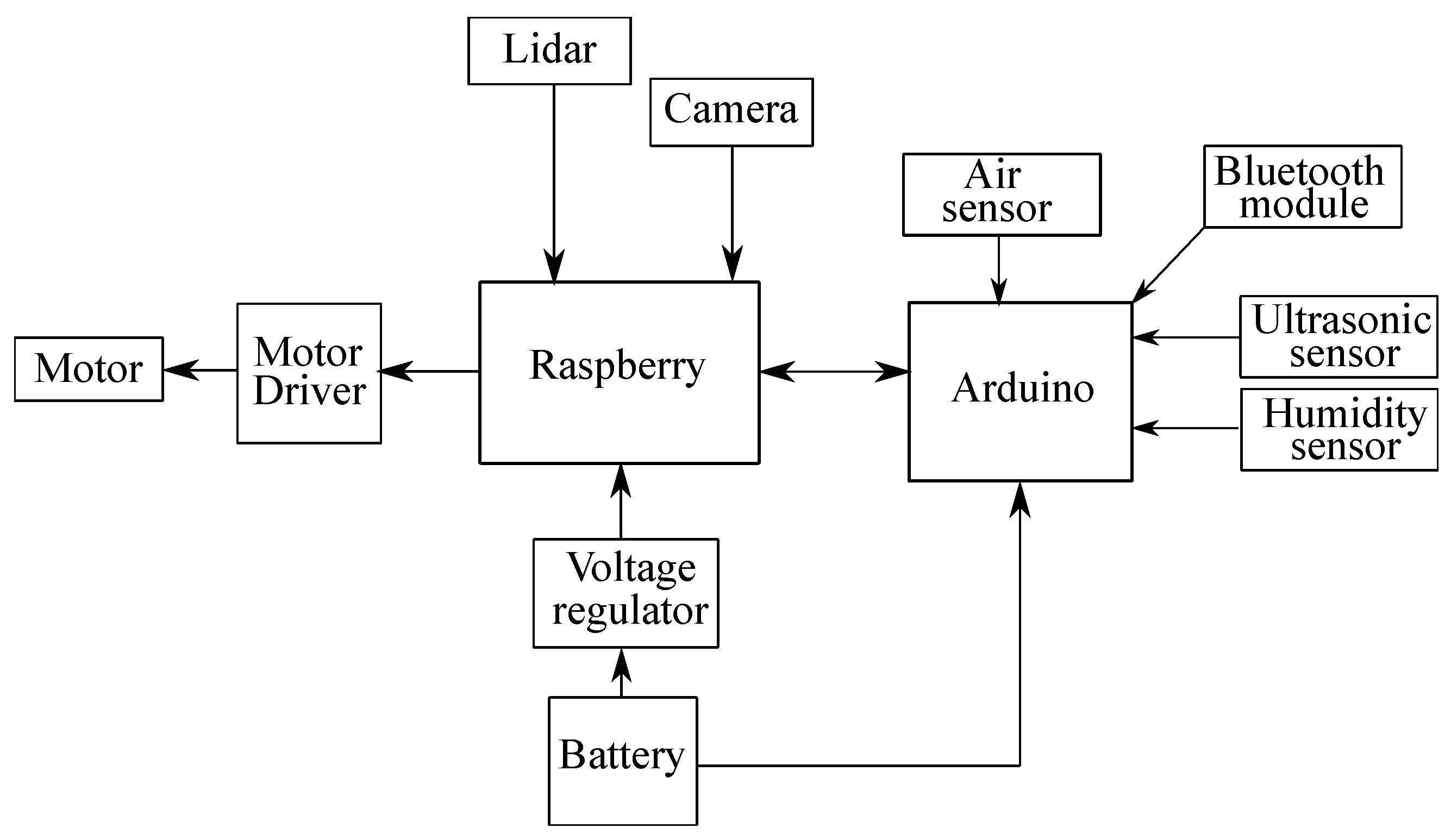
The use of high-performance GPUs to perform complex tasks significantly increases costs in the design of UGVs. In [145], to address this problem, a hybrid controller combining the Raspberry Pi model 3B board with the Arduino Uno board was proposed to control the UGV, as shown in Figure 18. Different tests showed that only 80% of the central processing unit (CPU) resources were used. In contrast, the remaining resources (along with the board pins) are available to integrate and manage other sensors for more complex applications.
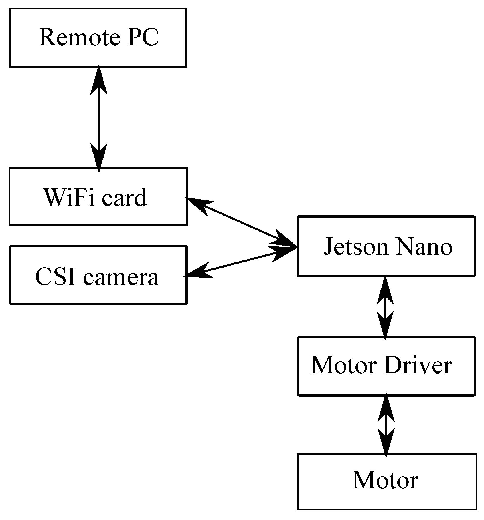
In [146], a Jetson Nano was used for motor control, a camera for video capture and image data acquisition, and a Wi-Fi card for communication with a personal computer (PC) equipped with an i7-9700 CPU, 16 GB RAM, and an RTX 2070 GPU as shown in Figure 19. The goal is to analyze the path, reprocess the data on the PC, and determine the configuration with the best performance.
The hardware design of the UGV system presented in [147] uses the NVIDIA Jetson Nano as the central processor, connected to various peripheral sensors to provide advanced functionality. These include a microphone for real-time audio streaming, a smoke sensor to detect fires outside the field of view, and a GPS module with an accuracy of 1-3 m for global localization. A 2D LIDAR is used for mapping, localization, and obstacle avoidance, while the IMU manages the robot’s orientation. In addition, an encoder provides odometry data, and a fourth-generation wireless (4G) modem provides connectivity for streaming and sending alerts. The system also features a stabilizing gyroscope to enhance mechanical stability and brushless direct current (BLDC) motors for improved locomotion. The added rear camera serves security purposes, while the Intel RealSense D435i provides depth data for facial recognition, object tracking, and obstacle avoidance.
In the software implementation, the Arduino Uno is programmed using the embedded C language to perform specific tasks. The Arduino Integrated Development Environment (IDE) is used for this purpose [145]. For the Raspberry Pi (https://www.raspberrypi.com/), the Python (https://www.python.org/) programming language is utilized, leveraging its powerful features and numerous useful predefined libraries. The code is written using Python 3 IDLE and executed within the Raspberry Pi operating system (OS).
In summary, Table 6 presents an overview of hardware systems used in unmanned ground vehicles reviewed in this study.

4.4. Navigation and Control

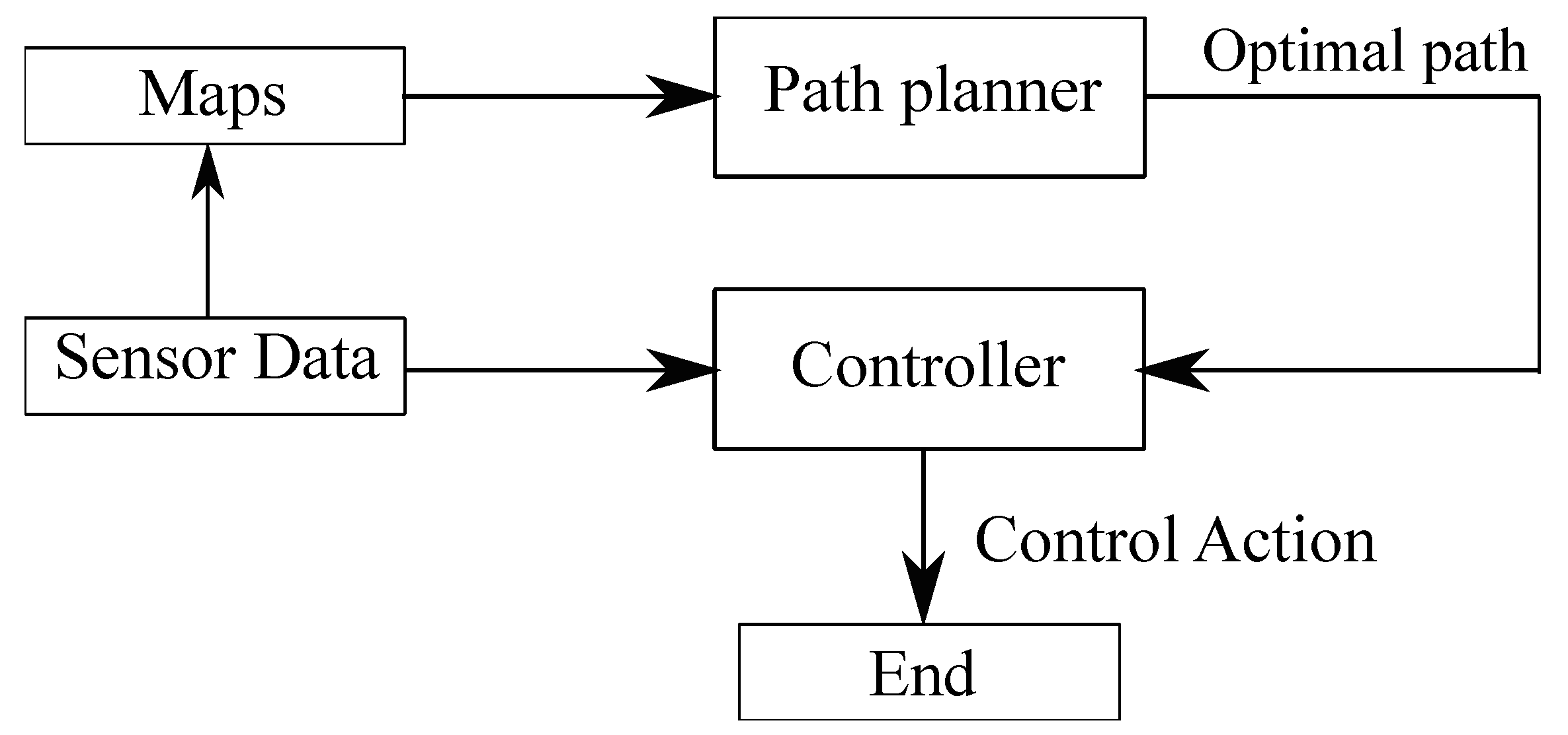
Addressing autonomous navigation and control is essential for the proper functioning of UGVs. However, route planning, an important step underlying effective control that is typically performed offline, should not be overlooked. Planning a path enables optimal path selection and simplifies the controller’s activities. In effect, the goal of planning is to define the path of the UGV. It receives as input a map and the start and end positions [148]. The planning is related to a discussion of system kinematics and does not account for robot dynamics. The trajectory and related measurements must be defined as input depending on the variables that need to be controlled. The control algorithm must allow the UGV to operate efficiently in any environment. This concept is schematized in Figure 20.
Due to space limitations, this section presents only a selection of the most widely used algorithms for path planning, autonomous navigation, and motion control. In [149], a path planning system is proposed that uses the adaptability of Partially Observable Markov Decision Processes (POMDP) [150,151]. The Artificial Potential Field (APF) method to realize a system capable of avoiding obstacles in an environment described through a TR-MAP (Topological Road Map) is analyzed in [152,153]. TR-MAPs are maps used for the navigation of autonomous robots. These maps represent spaces in terms of connections between significant places or nodes. In the article, several tests are conducted to determine the efficiency of the proposed method through comparisons with conventional algorithms such as Rapidly Exploring Random Tree (RRT) [154]. It is a probabilistic planning algorithm widely used in autonomous navigation [155], which builds a tree of configurations at each iteration. Specifically, at each step, a random node is generated. The algorithm searches for an existing node in the tree as close as possible to the node generated in the previous step, and, finally, the new node is inserted into the tree [156]. Another variant is the RRT-Star (RRT*) algorithm, which, unlike RRT, performs an optimization process to choose an optimal path.
Other known path planning algorithms are the D and D* [157,158]. The D-star (D*) algorithm was developed by Anthony Stentz [159]. It is adopted for autonomous robots moving in dynamic environments. Compared to other algorithms, it exhibits good adaptability to various scenarios and high efficiency in path computation. Some nonlinear controllers do not employ separate planning algorithms; instead, the planning and control parts are integrated. An example is the Nonlinear Model Predictive Control (NMPC) presented in [160]. This algorithm is implemented on Husky by Clearpath Robotics. The purpose is to enable the UGV to move crushed materials using a vehicle-mounted shovel safely. A hybrid control approach, Hybrid Model Predictive Control (HMPC), is reported in [161]. The developed controller can handle static and dynamic obstacles. The various tests conducted demonstrate that the HMPC is superior to a D* algorithm, both in terms of path length, travel time, and its ability to handle disturbances.
In [162], an autonomous control algorithm applied to a UGV that aims to move within crops organized in rows is proposed. The system has as input in the initial phase a map of the field from which to calculate the path coordinates. Then, an appropriate planner evaluates the trajectory to be followed. Navigation is guided by a signal based on GNSS (Global Navigation Satellite System) and AI (Artificial Intelligence). Specifically, when the system has a strong satellite signal, the vehicle utilizes only GNSS and inertial data, implementing Real-Time Kinematic corrections (RTK). On the other hand, when there is a poor satellite signal, a photo camera or a neural network is used. After analyzing the different types of handling, such as skid-steer and tracks, in the context of autonomous ground vehicles and their interaction with the terrain, it becomes essential to consider how advanced control systems can improve the adaptability and performance of the vehicle on various types of terrain.
Recent studies have explored precisely these control techniques and terra-mechanical modeling to address the challenges posed by complex and variable operating conditions. In particular, the survey provided in [163] combines the Extended Kalman Filter (EKF) with Model Predictive Control (MPC) to increase the adaptability and accuracy of the control system. By doing so, the MPC, utilizing a dynamic model of the vehicle, enables the generation of driving torque with faster responses than a speed-based controller. Meanwhile, the EKF estimates terrain drag coefficients in real-time, thereby enhancing the effectiveness of the MPC. Barrero et al. [164] developed a tracking system for a skid-steering agricultural vehicle based on predictive control. Because the vehicle operates in outdoor environments, a high-precision geolocation solution was implemented using a Kalman filter to fuse data from an IMU, wheel encoder, and GPS. Two controllers were implemented for autonomous tracking: a proportional one for linear speed and a Model-Based Predictive Controller (MBPC) for steering angle. The MBPC was developed through gray-box modeling and an incremental state-space strategy. The literature shows that the use of the MPC controller is optimal both on and off-road [165,166].
From this perspective, it is crucial to define accurate models of tire-soil interaction. For example, a model based on neural networks capable of adapting to deformable terrain was proposed in [167]. It follows that it is not only essential to design a system that is both structurally and energetically efficient, but also to design a navigation and control system that can effectively adapt to operating conditions by accurately estimating the state of the vehicle to optimize performance in variable terrain.
A key aspect in developing a control system is to keep in mind that UGVs interact with the terrain. For this reason, integrating terramechanics concepts should not be underestimated. Terramechanics is concerned with studying the interaction between vehicles and terrain. It allows the definition and identification of traction slip and stability. Integrating terramechanical models into navigation and control algorithms is essential to ensure high performance, especially on deformable terrain [168,169].

4.5. Path Planning and Energy Optimization

The interest in using UGVs across different scenarios has shifted the focus not only to route planning for a specific task, but also to energy-optimization planning [170]. In [171], an innovative approach is proposed that minimizes direction changes during navigation, resulting in more efficient, lower-energy coverage paths. In addition, the cost function to be minimized accounts for land characteristics and supports flexible, energy-efficient planning. Debnath et al. [172] analyze the main route-planning algorithms available, with a focus on energy efficiency. The use of genetic algorithms is helpful in this field for optimizing the path based on energy consumption, while also accounting for potential dynamic obstacles [173,174]. When evaluating hostile environments, such as off-road terrain, the challenges become even more complex. One key issue in these situations is torque saturation. To tackle this problem, a predictive controller is suggested in [175] to prevent saturation and achieve significant energy savings. A* planning algorithms are used to generate energy-efficient routes, and the effectiveness of the proposed method is validated through both simulations and experimental studies [176]. However, optimizing energy consumption is not the sole factor to consider in trajectory planning; potential obstacles, both static and dynamic, must also be addressed. Therefore, it is necessary to develop collision-avoidance algorithms that account for vehicle dynamics. Such methods generate optimal motion commands by searching over the space of actuation variables, ensuring robust navigation even in unstructured environments [177]. In more advanced contexts, such as space robotics, motion planning takes on an even more crucial role due to energy constraints and the operating environment. Optimal planning approaches that integrate the management of kinematic and dynamic constraints of the system are developed in these domains. A whole-body planner based on discrete dynamic programming and optimal interpolation, implemented in the ROS system and employed in the context of ESA missions, is proposed in [178]. In summary, route planning takes into account several variables, ranging from finding the shortest route to finding the trajectory with the lowest energy consumption to maximizing coverage of the operational area, ensuring smooth and safe movements even in the presence of static and dynamic obstacles.

5. Principal Applications

5.1. Precision Agriculture and Smart Farming

Integrating unmanned ground vehicles into digital agriculture is another significant development in Smart Agriculture. UGVs, such as Agri.q of the PIC4SeR, act as versatile platforms for acquiring data and performing field operations [179,180]. Through an architecture that allows navigation over uneven terrain and the use of robotic arms for precise operations, UGVs enable the collection of samples from soil and plants, as well as performing tasks such as fertilization [181,182]. Recent studies show the feasibility of implementing these technologies even through inexpensive solutions, such as using modified toy vehicles [183]. Additionally, artificial and swarm intelligence techniques can optimize collaborative data collection, making unmanned ground vehicles a powerful tool for precision agriculture [184]. These technologies enable more efficient management of agricultural resources, improving yields and reducing revenue losses.
Special emphasis is given to the use of UGVs in food crops, including a discussion of their environmental and economic impacts. Factors related to future developments, management, and performance of UGVs are also analyzed, with strategies to demonstrate to farmers the safety and profitability of implementing this technology [185]. UGVs are commonly used to detect animal droppings, monitor crop growth, identify storm or flood damage, and detect unwanted pests or molds. Navigation between the rows is done through machine vision cameras and GPS systems, which enable the detection of crop contours and edges, ensuring precise navigation without damage [186].
In [187], the Thorvald (Saga Robotics, Oslo, Norway) is presented. This UGV features both four-wheel skid-steer motion and steering with Ackermann. Bettucci et al. compared an autonomous tractor with a conventional one [188]. The comparison was made between corn seeding using a conventional tractor (Lamborghini R4.95) equipped with a 4-row Monosem NG Plus seeder (the working width is 3 m) and an autonomous tractor (Robotti 150d).
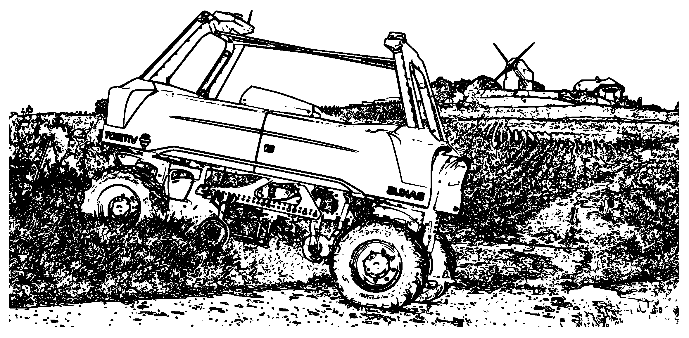
Another interesting example of applying UGVs in agriculture is the Bakus, shown in Figure 21, developed by Vitibot [189].
This vehicle is designed for viticulture. It performs operations such as tilling the soil, monitoring plant health, and crop management. All these operations are carried out in total autonomy.

5.2. Military Scope and Defense Applications

In the military field, unmanned ground vehicles are mainly used to defuse bombs and other explosive devices, operating via remote control to reduce the risk to personnel. An example of a more advanced UGV is the Mobile Detection Assessment Response System (MDARS), which was developed to meet various security needs [191]. In particular, MDARS is a vehicle designed to conduct semi-autonomous patrols, assess barriers, and respond to potential intrusions into military installations, thereby improving force protection and reducing risks to soldiers and workforce requirements in surveillance and security operations. The developed platform is smaller than a compact automobile and can operate in a single lane. Software developed by the government (Navy SPAWAR Systems Center, San Diego, CA, USA), called Multiple Resource Host Architecture (MRHA), is used for control planning and task execution. The use of UGVs for surveillance applications is increasing [192].
During World War II, the German Army commissioned Borgward to design a remote-controlled vehicle, which was later named Goliath (Gerät 67 or SdKfz.302), intended for carrying explosives to enemy targets [193]. It was 1.5 m long, 370 kg in weight, and could carry 80 kg of explosives for 800 m, with a maximum speed of 10 km per hour. A three-wire electric cable controlled it for movement and the detonation of explosives.
An unmanned ground vehicle designed for military-oriented applications, capable of autonomously tackling predefined tasks as much as possible, requiring operator support only in complex and unexpected decision-making situations, was presented in [194]. In the system, the electric actuators for remote vehicle control are designed to be disconnected for manual driving while maintaining road legality. Additionally, a removable linear actuator adjusts the transmission, while a DC motor drives the steering wheel via a toothed belt, allowing for disconnection and manual driving. Additionally, the braking system utilizes an actuator that pushes the brake pedal without physically attaching to it, allowing for operator intervention at any time. Moreover, potentiometers and limit switches provide feedback on movements, preventing overshooting. This design ensures the autonomy and safe operation of the vehicle.
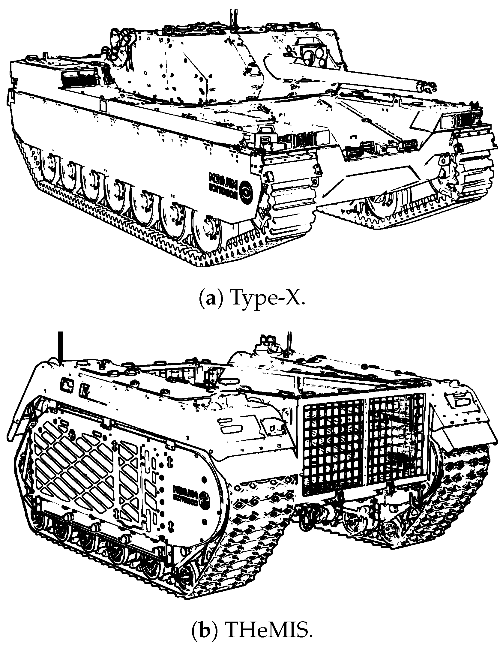
Several companies are experimenting with the use of UGVs in the military. In this vein, MILREM ROBOTICS has developed two hybrid UGV configurations, THeMIS and Type-X [195]. They are hybrid robotic platforms with a diesel engine, a current generator, and an accumulator. More specifically, THeMIS is an unmanned ground vehicle deployed in the counterinsurgency mission, Operation Barkhane, in Mali. It has been used for various purposes such as transportation, arming, ordnance deactivation, and intelligence operations support, depending on the mission [196]. THeMIS has been acquired by 16 countries, including eight NATO members: Estonia, France, Germany, the Netherlands, Norway, Spain, the United Kingdom, and the United States [197].
The Type-X Combat is designed to support mechanized units and to serve as a companion to main battle tanks. The Type-X Combat, shown in Figure 22a, is a UGV that can be equipped with various payloads. The vehicle can be equipped with various autocannons from 25 to 50 mm. The vehicle has dimensions of 600 × 290 × 220 cm and a total weight of 12000 kg, with a maximum load capacity of 4100 kg. It can reach a maximum road speed of 80 km per hour and a maximum speed in rough terrain of 50 km per hour, while the reverse speed is also 50 km per hour. The vehicle has a ground clearance of 50 cm and can negotiate slopes of up to 45 degrees, with a fording capacity of up to 150 cm depth. It has a turning radius of zero meters, providing exceptional maneuverability. In terms of protection, the vehicle complies with STANAG 4569 standards for kinetic energy and artillery protection of level 4, and it gives mine protection according to level 1.
The vehicle called THeMIS, shown in Figure 22b, is a UGV designed according to STANAG 3542 regulations for air transportability. It is 247 cm in length, 204 cm in width, and 117 cm in height. Its maximum speed reaches 20 km per hour. It has a mass of 1630 kg and can carry a maximum load of 1200 kg. It is designed to cope with slopes of up to 60% and side slopes of 30%, thus ensuring excellent mobility over rough terrain. Its ground clearance of 60 cm allows it to overcome obstacles and operate in complex environments, while its tractive force of 15,000 newtons enables it to haul heavy loads and bridge gaps of up to 90 cm. The UGV has state-of-the-art sensors for optimal vision and monitoring, including light detection and ranging (LIDAR), 1080p cameras, and Light-Emitting Diode (LED) and Infra-Red (IR) lights.
Another vehicle used in the military is the PackBot by iRobot, shown in Figure 3. It is a portable, combat-tested unmanned ground vehicle deployed in Afghanistan and Iraq. Yamauchi described several projects in which the PackBot has been used as the basis for developing new missions [198]. It has been used in the CHARS project, in which a sensor was designed to search for chemical and nuclear weapons; in the Griffon project, a hybrid UGV/UAV vehicle was developed [199,200]; in the Valkyrie project for the extraction and transportation of wounded; and in the Wayfarer project for the development of autonomous urban navigation capabilities [201]. In the Wayfarer project, a system was developed that enables the PackBot to perform reconnaissance operations autonomously. The system can follow a trajectory while avoiding obstacles and create a map of the environment using three-dimensional (3D) stereo vision, a planar LIDAR, GPS, and odometry.

5.3. Hazardous and Rescue Scenarios

Naranjo et al. presented an automation kit for converting military service vehicles into surveillance UGVs [202,203]. The kit was installed in a Spanish Army URO VAMTAC S3 vehicle. The purpose was to design an autonomous vehicle capable of performing various operations, including convoy movement, cyclic patrolling, and perimeter surveillance. The control logic follows the structure shown in Figure 16. In the non-civilian domain, UGVs are used for operations in hazardous environments [204]. During the Fukushima Daiichi nuclear disaster, small UGVs were utilized for observation missions in radioactive zones. In addition, the use of these robotic systems is critical in emergencies, where psychological stress can lead to significant human errors, as presented in [205]. Through special sensors, these robots can collect data from their surrounding environment, including temperature and the concentration of hazardous substances. Other studies have focused instead on developing methods to generate real-time 3D maps and evaluate optimal routes for rescue operations [206]. UGVs are also used for autonomous crack detection in structures damaged by natural disasters [207].
UGVs can also be utilized to perform missions in hazardous environments. The use of these systems is highly advantageous, as they keep operators out of dangerous environments. Additionally, through advanced systems, it is possible to assess risk and predict disasters using specialized algorithms [208]. For example, in chemical, biological, and nuclear disasters, robots are used to identify and locate radiation sources. The human operator can, in this way, monitor the environment from a remote location without coming into direct contact with the radiation present [209]. Unmanned ground vehicles have also proven useful in disaster scenarios caused by natural events, such as volcanic eruptions, seismic events, or hurricanes [210,211]. The use of such autonomous systems can also bring significant improvements to the industrial environment. In confined spaces, such as those in the oil and gas or hot metal industries, these systems can reduce the number of accidents [212]. Another environment in which a UGV can be used is exploration in the field of geographic exploration, such as that of volcanoes [213].
The primary threat to humans in these environments is the potential for sudden eruptions. The ROVOVOLC project was created in this spirit, namely, the development of a robotic system used for exploration. The platform is equipped with a SCARA manipulator used for gas sampling and rock collection [214,215]. Another possible application is the use of these systems to put out fires. An example is the Notre Dame de Paris cathedral fire, where firefighters were forced to withdraw due to structural damage, and a UGV took their place [216]. Additionally, small systems can be used for fire prevention inside houses and apartments [217].

5.4. Building and Construction Sector

Using unmanned ground vehicles in the construction industry is an emerging technology that is gaining traction for several innovative applications. UGVs are being utilized to automate complex tasks, such as site preparation, monitoring, and interacting with challenging environments, thereby reducing risks to human workers and increasing efficiency. Conventional snooper trucks and lifting platforms are applied to carry out inspection activities. This equipment has limitations in terms of cost and equipment interruption. In this field, robotic systems can minimize costs, risks, and downtime to carry out structural inspection programs [80]. It is challenging for the construction industry to adopt new technologies. Lat et al. presented a review of the literature regarding the adaptation of the construction industry to new technologies, such as the use of drones and unmanned vehicles for site monitoring operations [218].
One of the most significant applications of UGVs is their ability to autonomously and accurately identify structural damage. For example, during inspections of reinforced concrete structures, UGVs can be equipped with advanced sensors such as thermal cameras and high-resolution imaging systems, enabling them to detect cracks, deformations, and other anomalies. In [84], a system based on three-dimensional reconstruction and a crack detection algorithm was proposed, highlighting the importance of data acquisition to assess the structural health of damaged buildings. A practical example of such an application is the condition assessment of the Arlington Memorial Bridge (AMB) [219], performed using the RABIT Bridge Inspection Tool [220]. This instrument integrates three semi-automated, non-destructive survey technologies. The RABIT is capable of collecting data at a speed of 1219.2 m per second, enabling it to cover 1.83 m wide on a lane in about three hours. In recent times, advances in Europe have led to the implementation of non-destructive investigation techniques and modular approaches for monitoring and data collection, particularly for key materials in civil engineering, such as steel and concrete [221,222].
Lim et al. proposed a mobile robot to perform inspections on bridge pavements [223]. The system detects cracks using a high-resolution camera and a unique algorithm called the Laplacian of Gaussian. The global crack map is obtained by calibrating the acquired images and locating the robot. Additionally, manual visual inspection of structures is often subject to subjective results, which can lead to prediction errors. Using an autonomous mobile robot equipped with Charge-Coupled Device (CCD) cameras enables the collection of objective data, providing accurate predictions of potential structural failure. Such a monitoring system was studied in [224], where its effectiveness was validated through both laboratory experiments and field trials. In this context, it is crucial to adopt a multisensor measurement approach with a high degree of automation, a role in which UGVs can play a significant role in collecting data autonomously and safely in harsh environments.
The speed and accuracy of data collection underscore the potential of UGVs in the construction industry, particularly in settings where worker safety is paramount and the efficiency of structural inspections of buildings is crucial. In addition, integrating innovative technologies, such as UGVs, can significantly improve the effectiveness and safety of infrastructure monitoring operations, paving the way for future trends in structural degradation monitoring.

6. Illustrative Example of the Powertrain Preliminary Design for a Typical UGV System

6.1. Design Strategy of a Typical UGV System

The design process of a UGV, or any other innovative system, follows clearly defined steps. The first step is a thorough, systematic review of existing literature, so that the work of other engineers and researchers can be fully understood and examined in detail. This approach not only helps identify issues related to the studied system but also allows analysis of other disciplinary areas to spot potential design constraints. For example, electrical or control aspects may raise critical problems due to decisions made during the mechanical design phase. Therefore, it is essential to assess and understand all possible challenges.
Additionally, a careful review helps to anticipate future trends and potential obstacles. After completing the analysis, the identified functional requirements define the design scope and facilitate the first development of a mockup. This stage is crucial for establishing the functional requirements, thereby enabling the creation of a system that aligns closely with the operational tasks it must perform. In this vein, the mockup plays a vital role in the design process by providing a visual representation of the product idea before actual implementation. It allows evaluation of the graphical appearance and element placement, making it easier to identify corrections or improvements early in the project. Although the mockup produced in this phase is quite different from an actual prototype, since it only partially possesses the functionality of the desired system, its usefulness lies in enabling extensive testing, as it serves as a design tool.
Once the system characteristics are defined, the implementation assessment is performed through a simple evaluation. Naturally, results at this stage are not final but serve as a foundation for subsequent phases and eventual optimization, taking into account all design variables. Following this procedure, initial measurements of the system are established, followed by the kinematic definition of its mechanical components. Next, a CAD model of the entire system can be developed, resulting in an multibody model. Within this multibody environment, various analyses can be conducted: from assessing constraint reactions at mechanical joints to creating control systems, evaluating the forces needed for locomotion, and determining the most suitable propulsion system. Finally, FEM analyses can be performed to assess the structural integrity of components and, if needed, optimize the entire system. Using this integrated methodology, which combines multiple methods, it is possible to design a model that considers all relevant design variables to achieve an optimal solution.

6.2. Preliminary Design of a Typical UGV System

The design or purchase of a UGV intended to operate in complex environments requires the analysis and definition of the functional requirements to choose or design the most reliable system possible. This process is critical as it allows the most appropriate solution to achieve the goal to be selected scientifically. A comprehensive illustrative example is, therefore, provided in this section, which leads to the proper preliminary design for the most suitable motors and mechanical transmission mechanisms of a given UGV.
In recent decades, the development of decision-making methods has enabled more effective handling of complex problems characterized by uncertainty, multiple criteria, and decision variables. Several methods, such as the Analytic Hierarchy Process (AHP), the Technique for Order of Preference by Similarity to Ideal Solution (TOPSIS), the Fuzzy Logic (FL), and the Scoring Method (SM), have been presented and evaluated in the literature [225,226]. These tools are widely used in fields such as engineering, business management, and other areas where integrating qualitative and quantitative judgments is crucial [227,228]. In the analysis presented in this section, on the other hand, the authors choose to use the SM to carry out the preliminary design of the locomotion system of the UGV considered as an illustrative example. This preference is due to the limited number of decision variables and options since this section is devoted to the preliminary dimensioning of the system under study.
The SM involves assigning a numerical value to each alternative based on specific criteria. Each criterion is evaluated based on its relative weight, which is determined by the importance assigned in the context of the problem. The sum of the weighted scores determines the final ranking of the alternatives. This method, while simple and easily applicable, has limitations when the criteria are numerous or the relationships between them are complex. Based on the information gathered from the literature and summarized in Section 4.1, Table 7 is defined. The scoring of the various criteria reported in Table 7 is based on the assumption that the system is intended to operate over non-cohesive and uneven terrain.
Subsequently, Table 8 summarizes the design data for evaluating the motor power. In particular, Table 8 shows the power output of the single motor and the maximum speed at which it can travel, varying the percentage slope i and thus the inclination angle α .
As shown in Figure 23, to estimate the power required by the motors to move the system, the main forces acting on the UGV in the x direction during motion on an inclined plane are taken into account. The forces considered in Figure 23 are the weight force F g , the rolling resistance F r , and the aerodynamic drag F d . The required power is estimated by taking into account these forces and an appropriate safety coefficient that accounts for mechanical losses and the efficiency of the propulsion system.
The velocity of the vehicle is considered constant, as reported in Table 8. The body is subjected to the gravitational field of the Earth, with an acceleration g equal to 9.81 m per second squared along the vertical Y-axis. Thus, as shown in Figure 23, the weight force can be divided into a parallel force component F and an orthogonal force component F , both evaluated with respect to the plane inclined of the angle α , which can be respectively expressed as:
F = F g cos ( α ) F = F g sin ( α )
where F g = m g is the total weight force, m is the mass of the entire system, and α refers to the slope of the inclined ground that is assumed as a variable parameter.
Having evaluated the force component denoted with F , it is possible to assess the force due to the rolling resistance F r by considering an appropriate coefficient C r defined in Table 8. In addition, an aerodynamic drag force F d should also be considered in this analysis, which can be readily derived by using a drag coefficient C d . For simplicity, the numerical value of C d given in Table 8 is chosen by considering the front surface of the UGV as a rectangular panel having a cross-sectional area equal to A. By doing so, one can write:
F r = C r F
and
F d = 1 2 C d ρ A v 2
where ρ represents the mass density of the air. Thus, the numerical evaluation of the rolling resistance force and the aerodynamic drag force can be easily performed employing Equations (2) and (3), respectively. On the other hand, the total net force along the x direction of the inclined plane denoted with F n is the sum of all the resistive forces, thereby representing the magnitude of the thrust force F t that should be multiplied by the velocity v to evaluate the total ideal motor power P m , i , as shown below:
F n = F r + F d + F = F t
where P m , i = F t v . It follows that:
P m , r = F t v N η
where P m , i = N η P m , r is the total ideal motor power and P m , r represents the real power that a single motor must possess, which is evaluated by dividing the increased required power by the product of the number of motors N and the motor efficiency η . In particular, Table 9 shows the power of the individual motor as the angle α changes.
The values given in Table 9 represent the preliminary values necessary for designing or selecting the type of tracked vehicle. For a more accurate assessment of the required power, more thorough calculations are necessary, taking into account factors such as loss of grip between the track and the ground, mechanical friction, and transmission losses.
In the preliminary design of the powertrain discussed in this section, a commercial motor with a power rating of 5 kW and a rotational speed of 6000 rpm per minute is chosen to meet the maximum power requirement. Considering the maximum speed of 25 km/h, it is possible to estimate the angular speed required for traction by considering a crown gear meshing with the track of radius R equal to 0.10 m. Thus, the corresponding angular velocity ω p can be evaluated using the following formula:
ω p = v p R = 69.44 ( rad rad s s )
By knowing the input and output rotational speeds, it is possible to estimate the effective transmission ratio, which is evaluated as the ratio of the motor rotational speed ω a to the required rotational speed ω p as given below:
ε e = ω a ω p = 15.84 ( )
To achieve the required output in terms of rotational speed, a reduction gear is necessary. In particular, the chosen gear is a compound planetary gear because it has a high reduction ratio, a compact size, and cannot be achieved with a single-stage gear. Compound planetary gearing is a commonly used gear system in complex mechanical applications, such as automatic transmissions, compact gearboxes, and transmission systems that require high reduction ratios in small spaces. A compound planetary gear is made up of at least two planetary stages that are interconnected in such a way as to achieve more articulated behavior than the simple planetary gear [229,230]. It is composed of different components: a central pinion (a), one or more satellites (c′–c″), a planet carrier (p), and a planet gear (b). The schematization is shown in Figure 24. It is important to note that, in Figure 24, c′ is the satellite gear belonging to the first stage and c″ is that of the second stage.
To use the mechanisms represented in Figure 24 as a gearbox, the system has the planetary gear (b) locked, and the output speed corresponds to the rotation speed of the carrier (p). For the gear train thus built, it is possible to define the Willis gear ratio ε 0 and then estimate the actual gear ratio ε e as made explicit in the following equation:
ε 0 = ω a ω p ω b ω p = z c z a z b z c = 14 . 84 ( ) ε e = 1 ε 0 = 1 ( ) + 14.84 ( ) = 15 . 84 ( )
The value of ε 0 is −14.86 ( ) , but, for simplicity of construction and size, it is rounded to −15 ( ) . Subsequently, this compound ratio was decomposed into two stages, having respectively mechanical transmission ratios given by ε 1 and ε 2 . In particular, a value for ε 1 of −3 ( ) and a value for ε 2 of 5 ( ) were defined for the first and second stages, respectively. It is easy to observe that the initial condition is met, as evidenced by the following equation:
ε 0 = 15 ( ) ε 0 = ε 1 ε 2
From a geometric point of view, a 3:1 reduction ratio is used for the first stage, making the stage compact because the wheels are similar in diameter. A ratio of 5:1 requires a noticeable difference in gearing for the second stage. This aspect does not pose a problem because the outer gear is larger, allowing the inner satellites to fit within the gear case. Additionally, there are structural advantages associated with the present design solution. With a 3:1 ratio, the torque transmitted to the first stage is relatively small. On the other hand, employing a 5:1 ratio at the first stage would already result in five times the input torque, thereby worsening wear and bending strength on both the wheel tooth and the shaft.
After evaluating the reduction ratios in both stages, the minimum number of teeth can be determined using the following formulation:
z a = 2 1 + 1 + 1 ε 1 1 ε 1 + 2 sin 2 ( θ ) 1 ε 1 + 2 sin 2 ( θ ) = 14.98 ( ) 15 ( )
being θ the pressure angle of the gear wheels, which is considered to be 20 degrees. This value represents an international standard that facilitates the production of interchangeable components, as defined by various ISO, DIN, and AGMA standards. From the gear ratio of the first stage, it is easy to estimate the number of teeth of the satellite gear using the following expression:
z c = z a ε 1 = 45 ( )
To estimate the number of teeth of the second satellite gear, the same formula can be used again, this time considering the sprocket-wheel pair. In this case, the wheel-wheel contact involves internal toothing. Therefore, the formulation of the number of teeth has the following expression:
z c = 2 1 + 1 1 ε 2 2 1 ε 2 sin 2 ( θ ) 2 1 ε 2 sin 2 ( θ ) = 18.79 ( ) 19 ( ) z b = z c ε 1 = 95 ( )
Considering, for simplicity, a modulus equal to 1 mm, it is possible to verify the equality of the wheel spacings of the wheel pairs a c and c b . Furthermore, taking into account the geometry of the gear thus designed and remembering that the diameter is related to the number of teeth according to the relation D = z m , it is possible to write:
D a + D c + D c = D b
By substituting the previously calculated results in Equation (13), one can easily verify that the equality reported in this equation is not satisfied. As a result, it is necessary to modify the system design properly. Since the diameters are not equal, one option is to consider using a different sprocket module for each stage. By enforcing the equality of the gearbases and explicitly expressing all the variables involved in the calculations as a function of the moduli of the two stages, one can formulate the following equations:
D a = z a m 1 , D c = z c m 1 D c = z c m 2 , D b = z b m 2
which leads to the following:
z a + z c m 1 + z c m 2 = z b m 2
By using the equality reported in Equation (15) and employing the numbers of teeth previously evaluated, it turns out that the ratio of the modulus of the first stage m 1 to the modulus of the second stage m 2 is equal to 1.26 ( ) . This ratio does not allow the selection of standard modules. It is, therefore, more appropriate to iterate the design process by changing the number of teeth. In particular, since the number of teeth of the solar gear wheel z a and the number of teeth of the second stage satellite gear wheel z c represent minimum numbers, it is possible to increase them by choosing, for example, z a = 16 ( ) and z c = 20 ( ) . Because of what was extensively discussed within the present section, it is immediate to estimate the number of teeth of the other gear wheels z c and z b as given in the following equation:
z c = ε 1 z a = 48 ( ) z b = ε 2 z c = 100 ( )
Based on the relation of equality of center distances, it is possible to estimate the ratio between the moduli of the first and second stages, which for this tooth combination, turns out to be 1.25 ( ) . Thus, it is possible to define a module m 1 of 1.25 mm for the first stage, while a module m 2 of 1 mm is chosen for the second stage. Finally, the results of the gear mechanism thus designed are shown in Table 10.
The values represented in the Table 10 correspond to first-attempt values that satisfy the kinematic conditions of the rotor system. Following this initial, approximate but effective design, detailed structural verifications must be carried out to ensure and verify the proper functioning of the system.

7. Summary, Conclusions, and Future Work

7.1. Synopsis of the Review and Research Work

The authors’ research interests encompass the analysis of multibody mechanical systems, nonlinear optimal control, and applied structural identification. Within this framework, the study of Unmanned Ground Vehicles (UGVs) stands out as a particularly pertinent area that aligns seamlessly with the authors’ expertise and research focus. Consequently, this paper is dedicated to providing a thorough review of the theoretical advancements, practical developments, and contemporary challenges in the computer-aided design, modeling, and simulation of autonomous UGVs that are transforming modern mechanical engineering applications.
The present investigation can be divided into two main phases: a comprehensive research phase and a preliminary design phase. The research followed a defined and structured path, beginning with a historical background of the topic and then developing through a detailed literature review. This initial phase is the true strength of the work, as it provides a solid and well-documented foundation on which the entire analysis rests. All of this enabled the authors to understand the problems associated with the world of UGVs. The implementation of traction and control systems presents a challenge in both the design and purchase phases of a vehicle. Additionally, this paper highlights the applicability of these systems in various engineering fields.
In the first part of this review, the development of unmanned ground vehicles up to 2005 was examined using the traditional narrative approach. The historical review in this section highlights the evolution of these multidisciplinary engineering systems over time, as well as the areas of application in which they emerged. Subsequently, a systematic literature review approach was employed to derive an unbiased analysis of the main issues and principal challenges in this new and promising field of research, with a particular focus on mechanical engineering applications.

7.2. Current Trends, Performance Limitations, and Future Developments

In recent years, the field of UGV systems has made significant progress. In particular, the literature demonstrates a growing interest in the use of increasingly advanced systems, both from a technological standpoint and in the application of advanced materials [231,232]. The ability to utilize high computational power has enabled the development of increasingly accurate virtual models. Additionally, the use of advanced sensors has enabled the definition of what is known as the digital twin [233,234]. Recent research work highlights that such systems enable real-time monitoring and reduced maintenance costs by predicting failures [7,235]. In addition, the use of these systems, integrated with artificial intelligence algorithms and optimal control, enables the optimal utilization of available energy, achieving the goal of energy savings [171,236].
Unlike systems that operate in wide spaces, such as UAVs, UGV systems face several challenges, including operating in rugged terrain, navigating dynamic obstacles, and navigating confined spaces [237,238,239]. Achieving these goals is not only a technological challenge but also a mechanical one. Indeed, the use of advanced sensing facilitates overcoming possible obstacles, but the use of advanced and pioneering mechanical systems is also of importance. The possibility of developing modular or hybrid platforms could be of considerable interest. Possible solutions could be the combination of wheels and tracks or wheels and legs (wheel-legged systems), thereby providing better operational versatility [240]. Another innovative aspect could be the development of amphibious platforms and those that are multi-domain, i.e., capable of operating both on land and in water [241,242] or transforming into flying drones [243]. Prototypes of transformable vehicles capable of combining land locomotion and vertical flight are being developed [244]. These technologies are increasingly the subject of interest from both civilian and military sectors. Future research on UGVs will be most likely primarily based on addressing and solving these new technological challenges.
Despite the considerable progress made in recent years and analyzed in the previous sections, some limitations need to be emphasized. Liu et al. [245] conducted a review of path-planning methods for mobile robots and identified several critical issues. Most models use a grid-based approach, which is poorly suited to three-dimensional environments, leading the robot to lose accuracy in its movements. Another problem that has emerged is that most of the research is developed in virtual environments and not tested experimentally. In addition, most of the proposed planning algorithms assume static or little variable environments [246]. This turns out to be a limitation, as UGVs may exhibit poor adaptability in complex, unpredictable scenarios. Another limitation is the real-time detection of obstacles. The literature highlights that fusion sensor systems are not sufficiently robust for real environments characterized by varying weather conditions, particularly in the presence of reflective surfaces [247]. In addition, there is evidence of poor generalization and transfer of the proposed methods.
Some algorithms are valid only in simulation or on specific robotic platforms. In light of these considerations and consistent with the discussion in the previous sections, it is possible to converge on some future research directions. There is undoubtedly a need to develop adaptive planning and control algorithms that can robustly handle dynamic, unexpected, real-time environments. It may be promising to integrate generative artificial intelligence techniques and large language models into perception and control systems [248,249]. Such models can help improve the semantic understanding of the scene and enable the robot to interpret its surroundings. Such approaches can be a step toward greater cognitive autonomy of UGVs. There is a need for greater integration among perception, sensory fusion, and real-time obstacle-avoidance modules, with greater focus on off-road and unstructured scenarios. Finally, there is a need to deepen safety aspects and human-robot interaction [250]. The interaction must advance in a way that ensures transparency in decision-making, trust, and predictability.

7.3. Conclusive Discussion and Final Remarks

Due to the rapid developments in the engineering and scientific fields of unmanned ground vehicles, a substantial number of studies have been published on these vehicles from 2005 to 2024. For this reason, conducting an unbiased and objective historical review using the narrative method during this period has become quite challenging, if not impossible. Therefore, in the present investigation, a systematic literature review approach was employed to conduct an impartial, objective, standardized, and systematic review of studies published during this timeframe. Specifically, 581 studies were extracted from the primary databases and underwent bibliographic analysis in this investigation. This process revealed the most cited studies, the most productive authors, their social structure, and key research areas. In this context, a first research cluster addressing the main topics of vehicle design, cooperation with unmanned aerial vehicles, path planning, and obstacle avoidance was identified; a second research cluster focusing on trajectory tracking, agricultural applications, and advanced control applications emerged; and a third and last research cluster concentrating on autonomous driving, mapping, and sensor topics was found.
The work conducted in this research enabled the acquisition of in-depth knowledge about the various subsystems that comprise a typical UGV. The knowledge gained through the systematic review approach will allow the design and development of a UGV with extreme detail, suitable for various application contexts. The purpose of this work is to lay the foundation for designing a multitask platform that exhibits high stability and maneuverability, even in unstructured terrain.
Future research will focus on developing the Computer-Aided Design (CAD) model of the example of the UGV system described in the paper, as well as its subsequent multibody modeling. Building on this mechanical modeling, several directions can be pursued in future work. For instance, advanced control algorithms can be developed, and computer codes based on the Finite Element Method (FEM) can be implemented for the structural optimization of the system components under study. Furthermore, the theme of sustainability can be explored by utilizing energy management controls to enhance autonomy and incorporating sustainable materials into the system construction. All these fundamental issues concerning the mechanical modeling of UGVs will be explored, addressed, and solved in future investigations.

Author Contributions

This paper was principally devised and developed by the first author (R.L.R.) and by the second Author (Ö.E.G.). Great support in the development of this research work was provided by the third author (C.M.P.). The detailed review carried out by the fourth author (D.G.) considerably improved the quality of the work. The manuscript was written with substantial contributions from all authors. All authors have read and agreed to the published version of the manuscript.

Funding

This research received no external funding.

Institutional Review Board Statement

Not applicable.

Informed Consent Statement

Not applicable.

Data Availability Statement

The data presented in this study are available from the corresponding author upon reasonable request.

Conflicts of Interest

Rosario La Regina was employed by the company MEID4, Research Center for AI-based Innovation. The remaining authors declare that the research was conducted in the absence of any commercial or financial relationships that could be construed as a potential conflict of interest.

References

  1. Hamed, A.M.; Jayakumar, P.; Letherwood, M.D.; Gorsich, D.J.; Recuero, A.M.; Shabana, A.A. Ideal compliant joints and integration of computer aided design and analysis. J. Comput. Nonlinear Dyn. 2015, 10, 021015. [Google Scholar] [CrossRef]
  2. Foucault, G.; Cuillière, J.C.; François, V.; Léon, J.C.; Maranzana, R. Adaptation of CAD model topology for finite element analysis. Comput.-Aided Des. 2008, 40, 176–196. [Google Scholar] [CrossRef]
  3. Yoo, S.; Lee, S.; Kim, S.; Hwang, K.H.; Park, J.H.; Kang, N. Integrating deep learning into CAD/CAE system: Generative design and evaluation of 3D conceptual wheel. Struct. Multidiscip. Optim. 2021, 64, 2725–2747. [Google Scholar] [CrossRef]
  4. Louhichi, B.; Abenhaim, G.N.; Tahan, A.S. CAD/CAE integration: Updating the CAD model after a FEM analysis. Int. J. Adv. Manuf. Technol. 2015, 76, 391–400. [Google Scholar] [CrossRef]
  5. Wang, J.; Niu, W.; Ma, Y.; Xue, L.; Cun, H.; Nie, Y.; Zhang, D. A CAD/CAE-integrated structural design framework for machine tools. Int. J. Adv. Manuf. Technol. 2017, 91, 545–568. [Google Scholar] [CrossRef]
  6. Gujarathi, G.; Ma, Y.S. Parametric CAD/CAE integration using a common data model. J. Manuf. Syst. 2011, 30, 118–132. [Google Scholar] [CrossRef]
  7. Liang, H.; Chua, D.K.; Yeoh, J.K. Progress-Driven Waypoint Planning for UGV-based progress data collection and reality capture. Expert Syst. Appl. 2025, 280, 127512. [Google Scholar] [CrossRef]
  8. Li, Y.; Zhu, B.; Zhao, J.; Liu, Y. Terrain classification method based on fusion of vision and vehicle dynamics for UGV. Expert Syst. Appl. 2025, 279, 127495. [Google Scholar] [CrossRef]
  9. Shahar, F.S.; Sultan, M.T.H.; Nowakowski, M.; Łukaszewicz, A. UGV-UAV Integration Advancements for Coordinated Missions: A Review. J. Intell. Robot. Syst. 2025, 111, 69. [Google Scholar] [CrossRef]
  10. Anosri, S.; Panagant, N.; Champasak, P.; Bureerat, S.; Thipyopas, C.; Kumar, S.; Pholdee, N.; Yıldız, B.S.; Yildiz, A.R. A comparative study of state-of-the-art metaheuristics for solving many-objective optimization problems of fixed wing unmanned aerial vehicle conceptual design. Arch. Comput. Methods Eng. 2023, 30, 3657–3671. [Google Scholar] [CrossRef]
  11. Ait Saadi, A.; Soukane, A.; Meraihi, Y.; Benmessaoud Gabis, A.; Mirjalili, S.; Ramdane-Cherif, A. UAV path planning using optimization approaches: A survey. Arch. Comput. Methods Eng. 2022, 29, 4233–4284. [Google Scholar] [CrossRef]
  12. Sheridan, T. Telerobotics, Automation, and Human Supervisory Control, 1st ed.; MIT Press: Cambridge, MA, USA, 1992. [Google Scholar]
  13. Rehman, N.U.; Kumar, K.; Abro, G.e.M. Implementation of an autonomous path planning & obstacle avoidance UGV using SLAM. In Proceedings of the 2018 International Conference on Engineering and Emerging Technologies (ICEET), Lahore, Pakistan, 22–23 February 2018; pp. 1–5. [Google Scholar]
  14. Ni, J.; Hu, J.; Xiang, C. A review for design and dynamics control of unmanned ground vehicle. Proc. Inst. Mech. Eng. Part D J. Automob. Eng. 2021, 235, 1084–1100. [Google Scholar] [CrossRef]
  15. Baerveldt, A.J. Guest editorial: Agricultural robotics. Auton. Robot. 2002, 13, 5–7. [Google Scholar] [CrossRef]
  16. Quaglia, G.; Visconte, C.; Scimmi, L.S.; Melchiorre, M.; Cavallone, P.; Pastorelli, S. Robot arm and control architecture integration on a UGV for precision agriculture. In Proceedings of the Advances in Mechanism and Machine Science: Proceedings of the 15th IFToMM World Congress on Mechanism and Machine Science 15, Krakow, Poland, 30 June–4 July 2019; Springer: Berlin/Heidelberg, Germany, 2019; pp. 2339–2348. [Google Scholar]
  17. Rivera Chavez, Z.B.; Porcaro, A.; De Simone, M.C.; Guida, D. Improving Sustainable Viticulture in Developing Countries: A Case Study. Sustainability 2025, 17, 5338. [Google Scholar] [CrossRef]
  18. De Simone, M.C.; Veneziano, S.; Guida, D. Design of a non-back-drivable screw jack mechanism for the hitch lifting arms of electric-powered tractors. Actuators 2022, 11, 358. [Google Scholar] [CrossRef]
  19. Galar, D.; Kumar, U.; Seneviratne, D. Robots, Drones, UAVs and UGVs for Operation and Maintenance; CRC Press: New York, NY, USA, 2020. [Google Scholar]
  20. National Research Council; Division on Engineering and Physical Sciences. Technology Development for Army Unmanned Ground Vehicles; National Academies Press: Washington, DC, USA, 2003. [Google Scholar]
  21. Durst, P.J.; Monroe, G.; Bethel, C.L.; Anderson, D.T.; Carruth, D.W. A history and overview of mobility modeling for autonomous unmanned ground vehicles. In Proceedings of the Autonomous Systems: Sensors, Vehicles, Security, and the Internet of Everything, Orlando, FL, USA, 15–19 April 2018; SPIE: Bellingham, WA, USA, 2018; Volume 10643, pp. 103–113. [Google Scholar]
  22. Sharma, D.D.; Lin, J. Secure learning-based coordinated UAV–UGV framework design for medical waste transportation. Front. Remote Sens. 2024, 5, 1351703. [Google Scholar] [CrossRef]
  23. Asadi, K.; Suresh, A.K.; Ender, A.; Gotad, S.; Maniyar, S.; Anand, S.; Noghabaei, M.; Han, K.; Lobaton, E.; Wu, T. An integrated UGV-UAV system for construction site data collection. Autom. Constr. 2020, 112, 103068. [Google Scholar] [CrossRef]
  24. Shabana, A.A. Integration of computer-aided design and analysis: Application to multibody vehicle systems. Int. J. Veh. Perform. 2019, 5, 300–327. [Google Scholar] [CrossRef]
  25. Mikkola, A.; Shabana, A.A.; Sanchez-Rebollo, C.; Jimenez-Octavio, J.R. Comparison between ANCF and B-spline surfaces. Multibody Syst. Dyn. 2013, 30, 119–138. [Google Scholar] [CrossRef]
  26. Zhou, P.; Tang, S.; Liu, Y.; Zhao, J.; Sun, Z. Reconfigurable wheel-crawler-integrated walking mechanism design and kinetic analysis. Ind. Robot. Int. J. Robot. Res. Appl. 2023, 50, 633–647. [Google Scholar] [CrossRef]
  27. Cottrell, J.A.; Hughes, T.J.; Bazilevs, Y. Isogeometric Analysis: Toward Integration of CAD and FEA; John Wiley & Sons: New Delhi, India, 2009. [Google Scholar]
  28. Shabana, A.A. Geometrically accurate floating frame of reference finite elements for the small deformation problem. Proc. Inst. Mech. Eng. Part K J. Multi-Body Dyn. 2018, 232, 286–292. [Google Scholar] [CrossRef]
  29. Koul, P. Advancements in finite element analysis for tire performance: A comprehensive review. Int. J. Multidiscip. Res. Arts Sci. Technol. 2024, 2, 01–17. [Google Scholar] [CrossRef]
  30. Sanborn, G.G.; Shabana, A.A. On the integration of computer aided design and analysis using the finite element absolute nodal coordinate formulation. Multibody Syst. Dyn. 2009, 22, 181–197. [Google Scholar] [CrossRef]
  31. Piegl, L.; Tiller, W. The NURBS Book; Springer Science & Business Media: Berlin/Heidelberg, Germany, 2012. [Google Scholar]
  32. Grossi, E.; Desai, C.J.; Shabana, A.A. Development of geometrically accurate continuum-based tire models for virtual testing. J. Comput. Nonlinear Dyn. 2019, 14, 121006. [Google Scholar] [CrossRef]
  33. Pappalardo, C.M.; Lombardi, N.; Guida, D. A model-based system engineering approach for the virtual prototyping of an electric vehicle of class l7. Eng. Lett. 2020, 28, 215–234. [Google Scholar]
  34. Kuruvilla, J.K.; Seth, A.; Duttagupta, J.; Sharma, S.; Jaiswal, A. Structural Design and Analysis of 6-DOF Cylindrical Robotic Manipulators for Automated Agriculture; Apple Academic Press: Burlington, ON, Canada, 2024; pp. 147–168. [Google Scholar]
  35. Pappalardo, C.M.; Manca, A.G.; Guida, D. A Combined Use of the Multibody System Approach and the Finite Element Analysis for the Structural Redesign and the Topology Optimization of the Latching Component of an Aircraft Hatch Door. IAENG Int. J. Appl. Math. 2021, 51, 175–191. [Google Scholar]
  36. Gadola, M.; Chindamo, D.; Legnani, G.; Comini, M. Teaching automotive suspension design to engineering students: Bridging the gap between CAD and CAE tools through an integrated approach. Int. J. Mech. Eng. Educ. 2019, 47, 23–43. [Google Scholar] [CrossRef]
  37. Segura, C.C.; Hernandez, J.; Ramirez, H.; Aviles, O.; Mauledoux, M.; Dutra, M. Process Design for Autonomous Car Mining 1st Prototype “ACM1PT” to Help on Exploration Task on Outdoor Environments. Appl. Mech. Mater. 2016, 823, 447–452. [Google Scholar] [CrossRef]
  38. De Simone, M.C.; Veneziano, S.; Pace, R.; Guida, D. Multibody analysis of sloshing effect in a glass cylinder container for visual inspection activities. Appl. Sci. 2024, 14, 4522. [Google Scholar] [CrossRef]
  39. Yépez-Ponce, D.F.; Montalvo, W.; Guamán-Gavilanes, X.A.; Echeverría-Cadena, M.D. Route Optimization for UGVs: A Systematic Analysis of Applications, Algorithms and Challenges. Appl. Sci. 2025, 15, 6477. [Google Scholar] [CrossRef]
  40. Bonera, E.; Gadola, M.; Chindamo, D.; Morbioli, S.; Magri, P. Integrated design tools for model-based development of innovative vehicle chassis and powertrain systems. In Proceedings of the International Conference of the Italian Association of Design Methods and Tools for Industrial Engineering, Modena, Italy, 9–10 September 2019; Springer: Berlin/Heidelberg, Germany, 2019; pp. 118–128. [Google Scholar]
  41. Sharkey, N.; Sharkey, A. Electro-mechanical robots before the computer. Proc. Inst. Mech. Eng. Part C J. Mech. Eng. Sci. 2009, 223, 235–241. [Google Scholar] [CrossRef]
  42. Cyberneticzoo. 1914–Seleno, The Electric Dog–Hammond & Miessner. 2025. Available online: https://cyberneticzoo.com/precyber/1914-seleno-the-electric-dog-hammondmiessner/ (accessed on 28 February 2025).
  43. Everett, H. Unmanned Systems of World Wars I and II; MIT Press: Cambridge, MA, USA, 2015. [Google Scholar]
  44. Sukhopytnaya Torpeda Aubriot-Gabet: Torpille électrique (France). 2017. Available online: https://en.topwar.ru/123927-suhoputnaya-torpeda-aubriot-gabet-torpille-electrique-franciya.html (accessed on 10 January 2025).
  45. Marques, M.R.M. Reference Model for Interoperability of Autonomous Systems. Ph.D. Thesis, Universidade NOVA de Lisboa (Portugal), Lisbon, Portugal, 2018. [Google Scholar]
  46. Germain, É. De la guerre à distance à une guerre désincarnée: Les enjeux moraux d ‘une globalization du champ de bataille. Int. Rev. Red Cross 2014, 95, 28. [Google Scholar]
  47. Cooke, T. A Timeline of Military Robots and Drones; Capstone: North Mankato, MN, USA, 2017. [Google Scholar]
  48. Rondelli, V.; Franceschetti, B.; Mengoli, D. A review of current and historical research contributions to the development of ground autonomous vehicles for agriculture. Sustainability 2022, 14, 9221. [Google Scholar] [CrossRef]
  49. Larcombe, M. Mobile robots for industrial use. Ind. Robot. Int. J. 1979, 6, 70–76. [Google Scholar] [CrossRef]
  50. Marce, L.; Julliere, M.; Place, H.; Perrichot, H. A semi-autonomous remote controlled mobile robot. Ind. Robot. Int. J. 1980, 7, 232–235. [Google Scholar] [CrossRef]
  51. Heer, E. The Role of Robots and Automation in Space; Technical Report; Jet Propulsion Laboratory, California Institute of Technology: Pasadena, CA, USA, 1978. [Google Scholar]
  52. Center, A.I. Shakey the Robot; SRI International Artificial Intelligence Center, Computer Science and Technology Division: Menlo Park, CA, USA, 1984. [Google Scholar]
  53. Orlando, N.E. An intelligent robotics control scheme. In Proceedings of the 1984 American Control Conference, San Diego, CA, USA, 6–8 June 1984; pp. 204–209. [Google Scholar]
  54. Giralt, G.; Chatila, R.; Vaisset, M. An integrated navigation and motion control system for autonomous multisensory mobile robots. In Autonomous Robot Vehicles; Springer: New York, NY, USA, 1990; pp. 420–443. [Google Scholar]
  55. Nilsson, N.J. A mobius automation: An application of artificial intelligence techniques. In Proceedings of the 1st International Joint Conference on Artificial Intelligence, IJCAI, Citeseer, Washington, DC, USA, 7–9 May 1969; Volume 69, pp. 509–520. [Google Scholar]
  56. Odedra, S.; Prior, S.D.; Karamanoglu, M. Investigating the Mobility of Unmanned Ground Vehicles. In Proceedings of the International Conference on Manufacturing and Engineering Systems, Huwei, Taiwan, 17–19 December 2009. [Google Scholar]
  57. Yerazunis, S. Autonomous Control of Roving Vehicles for Unmanned Exploration of the Planets; Technical Report; Rensselaer Polytechnic Institute: Troy, NY, USA, 1978. [Google Scholar]
  58. Doig, G.A. Electronic and Software Subsystems for an Autonomous Roving Vehicle; Technical Report; Rensselaer Polytechnic Institute: Troy, NY, USA, 1980. [Google Scholar]
  59. Lowrie, J.W.; Thomas, M.; Gremban, K.; Turk, M. The autonomous land vehicle (ALV) preliminary road-following demonstration. In Proceedings of the Intelligent Robots and Computer Vision IV; SPIE: Bellingham, WA, USA, 1985; Volume 579, pp. 336–350. [Google Scholar]
  60. Turk, M.; Morgenthaler, D.; Gremban, K.; Marra, M. Video road-following for the autonomous land vehicle. In Proceedings of the 1987 IEEE International Conference on Robotics and Automation, Raleigh, NC, USA, 31 March –3 April 1987; Volume 4, pp. 273–280. [Google Scholar]
  61. Turk, M.A.; Morgenthaler, D.G.; Gremban, K.D.; Marra, M. VITS-A vision system for autonomous land vehicle navigation. IEEE Trans. Pattern Anal. Mach. Intell. 1988, 10, 342–361. [Google Scholar] [CrossRef]
  62. Torii, T. Research in autonomous agriculture vehicles in Japan. Comput. Electron. Agric. 2000, 25, 133–153. [Google Scholar] [CrossRef]
  63. Shoemaker, C.M.; Bornstein, J.A. The Demo III UGV program: A testbed for autonomous navigation research. In Proceedings of the 1998 IEEE International Symposium on Intelligent Control (ISIC) Held Jointly with IEEE International Symposium on Computational Intelligence in Robotics and Automation (CIRA) Intell., Gaithersburg, MD, USA, 17 September 1998; pp. 644–651. [Google Scholar]
  64. Lane, G.R.; Lescoe, P.; Cooper, S. Unmanned ground vehicle control technology. In Proceedings of the NTC’91-National Telesystems Conference Proceedings, Atlanta, GA, USA, 26–27 March 1991; p. 329. [Google Scholar]
  65. Kumar, S.; Khan, G. Self controlled robot for military purpose. Int. J. Technol. Res. Eng. 2014, 1, 2347–4718. [Google Scholar]
  66. FLIR. PackBot-Unmanned Ground System. 2025. Available online: https://defense.flir.com/defense-products/packbot-525/ (accessed on 28 February 2025).
  67. Lindemann, R.A.; Voorhees, C.J. Mars Exploration Rover mobility assembly design, test and performance. In Proceedings of the 2005 IEEE International Conference on Systems, Man and Cybernetics, Waikoloa, HI, USA, 12 October 2005; Volume 1, pp. 450–455. [Google Scholar]
  68. NASA. Mars Exploration Rovers: Spirit and Opportunity. 2025. Available online: https://science.nasa.gov/mission/mars-exploration-rovers-spirit-and-opportunity/ (accessed on 15 January 2025).
  69. Zakrajsek, J.; McKissock, D.; Woytach, J.; Zakrajsek, J.; Oswald, F.; McEntire, K.; Hill, G.; Abel, P.; Eichenberg, D.; Goodnight, T. Exploration rover concepts and development challenges. In Proceedings of the 1st Space Exploration Conference: Continuing the Voyage of Discovery, Orlando, FL, USA, 30 January–1 February 2005; p. 2525. [Google Scholar]
  70. Braid, D.; Broggi, A.; Schmiedel, G. The TerraMax autonomous vehicle. J. Field Robot. 2006, 23, 693–708. [Google Scholar] [CrossRef]
  71. Ozguner, U.; Redmill, K.A.; Broggi, A. Team TerraMax and the DARPA grand challenge: A general overview. In Proceedings of the IEEE Intelligent Vehicles Symposium, Parma, Italy, 14–17 June 2004; pp. 232–237. [Google Scholar]
  72. ELÁŠ, J.; RAÚSOÁ, D. Trends of development in unmanned military motor vehicles. Univ. Rev. 2013, 7, 8–14. [Google Scholar]
  73. Blokhin, A.; Koshurina, A.; Krasheninnikov, M.; Dorofeev, R. The analytical review of the condition of heavy class military and dual-purpose unmanned ground vehicle. In Proceedings of the MATEC Web of Conferences. EDP Sciences, Lille, France, 6–11 July 2015; Volume 26, p. 04002. [Google Scholar]
  74. Czapla, T.; Wrona, J. Technology development of military applications of unmanned ground vehicles. In Vision Based Systemsfor UAV Applications; Springer: Heidelberg, Germany, 2013; pp. 293–309. [Google Scholar]
  75. Azmat, M.; Kummer, S. Potential applications of unmanned ground and aerial vehicles to mitigate challenges of transport and logistics-related critical success factors in the humanitarian supply chain. Asian J. Sustain. Soc. Responsib. 2020, 5, 3. [Google Scholar] [CrossRef]
  76. Moher, D.; Liberati, A.; Tetzlaff, J.; Altman, D.G. Preferred reporting items for systematic reviews and meta-analyses: The PRISMA statement. Int. J. Surg. 2010, 8, 336–341. [Google Scholar] [CrossRef]
  77. Aria, M.; Cuccurullo, C. bibliometrix: An R-tool for comprehensive science mapping analysis. J. Inf. 2017, 11, 959–975. [Google Scholar] [CrossRef]
  78. Tokekar, P.; Vander Hook, J.; Mulla, D.; Isler, V. Sensor planning for a symbiotic UAV and UGV system for precision agriculture. IEEE Trans. Robot. 2016, 32, 1498–1511. [Google Scholar] [CrossRef]
  79. Li, J.; Deng, G.; Luo, C.; Lin, Q.; Yan, Q.; Ming, Z. A hybrid path planning method in unmanned air/ground vehicle (UAV/UGV) cooperative systems. IEEE Trans. Veh. Technol. 2016, 65, 9585–9596. [Google Scholar] [CrossRef]
  80. Lattanzi, D.; Miller, G. Review of robotic infrastructure inspection systems. J. Infrastruct. Syst. 2017, 23, 04017004. [Google Scholar] [CrossRef]
  81. Carlson, J.; Murphy, R.R. How UGVs physically fail in the field. IEEE Trans. Robot. 2005, 21, 423–437. [Google Scholar] [CrossRef]
  82. Yoon, Y.; Shin, J.; Kim, H.J.; Park, Y.; Sastry, S. Model-predictive active steering and obstacle avoidance for autonomous ground vehicles. Control Eng. Pract. 2009, 17, 741–750. [Google Scholar] [CrossRef]
  83. Yu, H.; Meier, K.; Argyle, M.; Beard, R.W. Cooperative path planning for target tracking in urban environments using unmanned air and ground vehicles. IEEE/ASME Trans. Mechatronics 2014, 20, 541–552. [Google Scholar] [CrossRef]
  84. Torok, M.M.; Golparvar-Fard, M.; Kochersberger, K.B. Image-based automated 3D crack detection for post-disaster building assessment. J. Comput. Civ. Eng. 2014, 28, A4014004. [Google Scholar] [CrossRef]
  85. Wong, J.Y.; Huang, W. “Wheels vs. tracks”—A fundamental evaluation from the traction perspective. J. Terramech. 2006, 43, 27–42. [Google Scholar] [CrossRef]
  86. Qin, H.; Meng, Z.; Meng, W.; Chen, X.; Sun, H.; Lin, F.; Ang, M.H. Autonomous exploration and mapping system using heterogeneous UAVs and UGVs in GPS-denied environments. IEEE Trans. Veh. Technol. 2019, 68, 1339–1350. [Google Scholar] [CrossRef]
  87. Manrique, C.; Pappalardo, C.; Guida, D. On the Analytical and Computational Methodologies for Modelling Two-wheeled Vehicles within the Multibody Dynamics Framework: A Systematic Literature Review. J. Appl. Comput. Mech. 2021, 8, 153–181. [Google Scholar] [CrossRef]
  88. Pérez Carrera, C.; Genel, Ö.E.; La Regina, R.; Pappalardo, C.M.; Guida, D. A comprehensive and systematic literature review on flying cars in contemporary research. J. Appl. Comput. Mech. 2025, 11, 642–666. [Google Scholar]
  89. Typiak, A. Requirements for mobility of platforms and power supply system for unmanned ground vehicles. J. KONES 2009, 16, 457–464. [Google Scholar]
  90. Colyer, R.; Economou, J. Comparison of steering geometries for multi-wheeled vehicles by modelling and simulation. In Proceedings of the 37th IEEE Conference on Decision and Control (Cat. No. 98CH36171), Tampa, FL, USA, 16–18 December 1998; Volume 3, pp. 3131–3133. [Google Scholar]
  91. Zhang, S.; Vantsevich, V.V. Turnability of a small UGV with individual wheel skid-steering on soft terrain. In Proceedings of the International Design Engineering Technical Conferences and Computers and Information in Engineering Conference, Quebec City, QC, Cananda, 26–29 August 2018; American Society of Mechanical Engineers: New York, NY, USA, 2018; Volume 51784, p. V003T01A017. [Google Scholar]
  92. Tran, T.H.; Kwok, N.M.; Scheding, S.; Ha, Q.P. Dynamic modelling of wheel-terrain interaction of a UGV. In Proceedings of the 2007 IEEE International Conference on Automation Science and Engineering, Scottsdale, AZ, USA, 22–25 September 2007; pp. 369–374. [Google Scholar]
  93. Narvesen, A.; Selekwa, M.F. Dynamics and Control of Four Wheeled Differentially Steered UGVs. In Proceedings of the ASME International Mechanical Engineering Congress and Exposition, Montreal, QC, Canada, 14–20 November 2014; Volume 46476, p. V04AT04A034. [Google Scholar]
  94. Baril, D.; Grondin, V.; Deschênes, S.P.; Laconte, J.; Vaidis, M.; Kubelka, V.; Gallant, A.; Giguere, P.; Pomerleau, F. Evaluation of skid-steering kinematic models for subarctic environments. In Proceedings of the 2020 17th Conference on Computer and Robot Vision (CRV), Ottawa, ON, Canada, 13–15 May 2020; pp. 198–205. [Google Scholar]
  95. Zhang, J.; Li, W.; Yan, J.; Shan, L. A Comparative Study of Ackermann Two-Axle Steering and Skid-Steering Mechanisms for Unmanned Ground Vehicles. In Proceedings of the International Conference on Autonomous Unmanned Systems, Nanjing, China, 9–11 September 2023; Springer: Berlin/Heidelberg, Germany, 2023; pp. 332–341. [Google Scholar]
  96. Lee, J.Y.; Han, S.; Kim, M.; Seo, Y.S.; Park, J.; Park, D.I.; Park, C.; Seo, H.; Lee, J.; Kim, H.S.; et al. Variable-stiffness–morphing wheel inspired by the surface tension of a liquid droplet. Sci. Robot. 2024, 9, eadl2067. [Google Scholar] [CrossRef] [PubMed]
  97. Jia, Z.; Smith, W.; Peng, H. Terramechanics-based wheel–terrain interaction model and its applications to off-road wheeled mobile robots. Robotica 2012, 30, 491–503. [Google Scholar] [CrossRef]
  98. Staicu, S. Dynamics equations of a mobile robot provided with caster wheel. Nonlinear Dyn. 2009, 58, 237–248. [Google Scholar] [CrossRef]
  99. Robo-Dyne. 4WD eXplorer: Four-Wheel-Driving Steering Robot Vehicle. 2024. Available online: https://robodyne-services.com/explorer-4wd-ugv-four-wheel-driving-steering-robot-vehicle/ (accessed on 13 December 2024).
  100. Samarini, E.; Shabana, A.A.; Grossi, E.; Somà, A. Integration of geometry and analysis for the study of continuum-based airless tyres of planetary wheeled robots. Int. J. Veh. Perform. 2020, 6, 446–480. [Google Scholar] [CrossRef]
  101. Sekhar, G.C.; Anjaneyulu, B.; Rao, K.; Rao, G.N. Design and analysis of four wheeler airless tire. Int. J. Eng. Sci. 2016, 6, 3365–3379. [Google Scholar]
  102. Patel, M.D.; Pappalardo, C.M.; Wang, G.; Shabana, A.A. Integration of geometry and small and large deformation analysis for vehicle modelling: Chassis, and airless and pneumatic tyre flexibility. Int. J. Veh. Perform. 2019, 5, 90–127. [Google Scholar] [CrossRef]
  103. Blundell, M.; Harty, D. The Multibody Systems Approach to Vehicle Dynamics; Elsevier: Oxford, UK, 2004. [Google Scholar]
  104. Shabana, A.A. Dynamics of Multibody Systems; Cambridge University Press: Cambridge, UK, 2020. [Google Scholar]
  105. Shabana, A.A. Computational Continuum Mechanics; John Wiley & Sons: Hoboken, NJ, USA, 2018. [Google Scholar]
  106. Samarini, E. Development of ANCF Airless Tire Model for the Mars Rover. Master’s Thesis, University of Illinois at Chicago, Chicago, IL, USA, 2020. [Google Scholar]
  107. Huang, G.; Yang, Z. Dynamic simulation of a rigid-flexible coupling positioning stage base on modified floating frame of reference formulation. In Proceedings of the 2nd International Conference on Applied Mathematics, Modelling, and Intelligent Computing (CAMMIC 2022), Kunming, China, 25–17 March 2022; SPIE: Bellingham, WA, USA, 2022; Volume 12259, pp. 721–727. [Google Scholar]
  108. Dickerson, S.L.; Lapin, B.D. Control of an omni-directional robotic vehicle with Mecanum wheels. In Proceedings of the NTC’91-National Telesystems Conference Proceedings, Atlanta, GA, USA, 26–17 March 1991; pp. 323–328. [Google Scholar]
  109. Abd Mutalib, M.A.; Azlan, N.Z. Prototype development of mecanum wheels mobile robot: A review. Appl. Res. Smart Technol. (ARSTech) 2020, 1, 71–82. [Google Scholar] [CrossRef]
  110. Park, I.; Pi, Y.; Park, J.; Kim, H.S.; Seo, T. Robust Optimal Design of a Shape-Morphing Wheel with High Speed Locomotion. Int. J. Precis. Eng. Manuf. 2025, 26, 1–11. [Google Scholar] [CrossRef]
  111. Sidi, M.H.A.; Hudha, K.; Abd Kadir, Z.; Amer, N.H. Modeling and path tracking control of a tracked mobile robot. In Proceedings of the 2018 IEEE 14th International Colloquium on Signal Processing & Its Applications (CSPA), Penang, Malaysia, 9–10 March 2018; pp. 72–76. [Google Scholar]
  112. Bruzzone, L.; Nodehi, S.E.; Fanghella, P. Tracked locomotion systems for ground mobile robots: A review. Machines 2022, 10, 648. [Google Scholar] [CrossRef]
  113. Fiedeń, M.; Bałchanowski, J. A mobile robot with omnidirectional tracks—Design and experimental research. Appl. Sci. 2021, 11, 11778. [Google Scholar] [CrossRef]
  114. Chen, P.; Mitsutake, S.; Isoda, T.; Shi, T. Omni-directional robot and adaptive control method for off-road running. IEEE Trans. Robot. Autom. 2002, 18, 251–256. [Google Scholar] [CrossRef]
  115. Ernits, R.M.; Hoppe, N.; Kuznetsov, I.; Uriarte, C.; Freitag, M. A new omnidirectional track drive system for off-road vehicles. In Proceedings of the XXII International Conference on Material Handling, Constructions and Logistics, Belgrade, Serbia, 4–6 October 2017. [Google Scholar]
  116. Teramoto, E.; Yabe, F.; Fukushima, K.; Narahara, H.; Kiyono, Y.; Togasi, S.; Kadono, M.; Nishimura, N.; Muramatsu, T. Development of a high-speed, half-tracked truck with metal-coreless rubber track. J. Terramech. 1996, 33, 113–123. [Google Scholar] [CrossRef]
  117. Grazioso, A.; Galati, R.; Mantriota, G.; Reina, G. Multibody simulation of a novel tracked robot with innovative passive suspension. In Proceedings of the International Conference of IFToMM ITALY, Naples, Italy, 7–9 September 2022; Springer: Berlin/Heidelberg, Germany, 2022; pp. 139–146. [Google Scholar]
  118. Liu, W.; Luo, X.; Zeng, S.; Zeng, L.; Wen, Z. The Design and Test of the Chassis of a Triangular Crawler-Type Ratooning Rice Harvester. Agriculture 2022, 12, 890. [Google Scholar] [CrossRef]
  119. Lawton, D.T.; Levitt, T.S.; McConnell, C.; Glicksman, J. Terrain models for an autonomous land vehicle. In Readings in Computer Vision; Elsevier: San Francisco, CA, USA, 1987; pp. 483–491. [Google Scholar]
  120. Crisan, A.V.; Morariu-Gligor, R.M. A study on the impact force in case of tamping rammers. Rom. J. Acoust. Vib. 2019, 16, 78–83. [Google Scholar]
  121. He, R.; Sandu, C.; Khan, A.K.; Guthrie, A.G.; Els, P.S.; Hamersma, H.A. Review of terramechanics models and their applicability to real-time applications. J. Terramech. 2019, 81, 3–22. [Google Scholar] [CrossRef]
  122. Tsitouridis, G. Terramechanics and Soil–Wheel Interactions for Road Vehicle Applications. Ph.D. Thesis, Loughborough University, Loughborough, UK, 2019. [Google Scholar]
  123. Jinzheng, Z.; Qi, W.; Qichun, J.; Peng, Z. Simulation Analysis of Interaction Mechanism Between Triangular Track and Ground Based on Bekker Theory. Acta Technica 62 No. 2B/2017, 1120 c 2017 Institute of Thermomechanics CAS, v.v.i. Available online: http://journal.it.cas.cz (accessed on 9 November 2025).
  124. Zhang, R.; Zhou, W.; Liu, H.; Gong, J.; Chen, H.; Khajepour, A. Similarities between Wheels and Tracks: A “Tire Model” for Tracked Vehicles. IEEE Trans. Veh. Technol. 2024, 73, 16416–16431. [Google Scholar] [CrossRef]
  125. Johnson, J.B.; Kulchitsky, A.V.; Duvoy, P.; Iagnemma, K.; Senatore, C.; Arvidson, R.E.; Moore, J. Discrete element method simulations of Mars Exploration Rover wheel performance. J. Terramech. 2015, 62, 31–40. [Google Scholar] [CrossRef]
  126. Jaiswal, S.; Korkealaakso, P.; Åman, R.; Sopanen, J.; Mikkola, A. Deformable terrain model for the real-time multibody simulation of a tractor with a hydraulically driven front-loader. IEEE Access 2019, 7, 172694–172708. [Google Scholar] [CrossRef]
  127. Kulju, S.; Ala-Ilomäki, J. Integration soil contact model—A flexible pressure-sinkage method for simulating low speed vehicles with wheels and tracks. Soil Tillage Res. 2025, 246, 106312. [Google Scholar] [CrossRef]
  128. Schäfer, B.; Gibbesch, A.; Krenn, R.; Rebele, B. Planetary rover mobility simulation on soft and uneven terrain. Veh. Syst. Dyn. 2010, 48, 149–169. [Google Scholar] [CrossRef]
  129. Taghavifar, H.; Rakheja, S. A novel terramechanics-based path-tracking control of terrain-based wheeled robot vehicle with matched-mismatched uncertainties. IEEE Trans. Veh. Technol. 2019, 69, 67–77. [Google Scholar] [CrossRef]
  130. Zhou, F.; Arvidson, R.E.; Bennett, K.; Trease, B.; Lindemann, R.; Bellutta, P.; Iagnemma, K.; Senatore, C. Simulations of mars rover traverses. J. Field Robot. 2014, 31, 141–160. [Google Scholar] [CrossRef]
  131. Acquah, K.; Chen, Y. Soil compaction from wheel traffic under three tillage systems. Agriculture 2022, 12, 219. [Google Scholar] [CrossRef]
  132. Bugár, M.; Stanák, V.; Ferencey, V. Hybrid powertrain conceptual design for unmanned ground vehicle. Sci. Mil. J. 2011, 6, 13. [Google Scholar]
  133. Salama, M.A.; Vantsevich, V.V.; Way, T.R.; Gorsich, D.J. UGV with a distributed electric driveline: Controlling for maximum slip energy efficiency on stochastic terrain. J. Terramech. 2018, 79, 41–57. [Google Scholar] [CrossRef]
  134. Broderick, J.; Hartner, J.; Tilbury, D.M.; Atkins, E.M. Modeling and simulation of an unmanned ground vehicle power system. In Proceedings of the Unmanned Systems Technology XVI, Baltimore, ML, USA, 5–8 May 2014; SPIE: Bellingham, WA, USA, 2014; Volume 9084, pp. 46–55. [Google Scholar]
  135. Baldic, J.; Osenar, P.; Lauder, N.; Launie, P. Fuel cell systems for long duration electric UAVs and UGVs. In Proceedings of the Defense Transformation and Net-Centric Systems, Orlando, FL, USA, 12–16 April 2010; SPIE: Bellingham, WA, USA, 2010; Volume 7707, pp. 9–17. [Google Scholar]
  136. Bugár, M.; Ferencey, V. Control management system of the hybrid—Electric power sources simulation for unmanned ground vehicle. In Proceedings of the 2016 Cybernetics & Informatics (K&I), Orlando, FL, USA, 5–8 July 2016; pp. 1–6. [Google Scholar]
  137. González, E.L.; Cuesta, J.S.; Fernandez, F.J.V.; Llerena, F.I.; Carlini, M.A.R.; Bordons, C.; Hernandez, E.; Elfes, A. Experimental evaluation of a passive fuel cell/battery hybrid power system for an unmanned ground vehicle. Int. J. Hydrogen Energy 2019, 44, 12772–12782. [Google Scholar] [CrossRef]
  138. Barreras, F.; Maza, M.; Lozano, A.; Báscones, S.; Roda, V.; Barranco, J.E.; Cerqueira, M.; Vergés, A. Design and development of a multipurpose utility AWD electric vehicle with a hybrid powertrain based on PEM fuel cells and batteries. Int. J. Hydrogen Energy 2012, 37, 15367–15379. [Google Scholar] [CrossRef]
  139. Farella, A.; Paciolla, F.; Quartarella, T.; Pascuzzi, S. Agricultural unmanned ground vehicle (UGV): A brief overview. In Proceedings of the International Symposium on Farm Machinery and Processes Management in Sustainable Agriculture, Lublin, Poland, 12–14 June 2024; Springer: Berlin/Heidelberg, Germany, 2024; pp. 137–146. [Google Scholar]
  140. Guo, L.; Zhang, X.; Zou, Y.; Han, L.; Du, G.; Guo, N.; Xiang, C. Co-optimization strategy of unmanned hybrid electric tracked vehicle combining eco-driving and simultaneous energy management. Energy 2022, 246, 123309. [Google Scholar] [CrossRef]
  141. Tan, Y.; Xu, J.; Ma, J.; Li, Z.; Chen, H.; Xi, J.; Liu, H. A transferable perception-guided EMS for series hybrid electric unmanned tracked vehicles. Energy 2024, 306, 132367. [Google Scholar] [CrossRef]
  142. Minh, T.B.; Luan, H.T.; Nhu, T.Q.; Duong, B.M. MiniRos: An autonomous UGV robot for education and research. In Proceedings of the 2021 International Conference on System Science and Engineering (ICSSE), Nha Trang City, Vietnam, 26–28 August 2021; pp. 170–175. [Google Scholar]
  143. Arana, G.; Garcia, A.; Nguyen, J.; Velazquez, A. Final Design Report: NavG – NGCP. California Polytechnic State University, San Luis Obispo, CA, USA. Northrop Grumman Collaboration Project (NGCP) Capstone Report. 2020. Available online: https://www.justinnuwin.com/projects/cp-capstone/report.pdf (accessed on 9 November 2025).
  144. Teskeredzic, E.; Akagic, A. Low cost UGV platform for autonomous 2D navigation and map-building based on a single sensory input. In Proceedings of the 2020 7th International Conference on Control, Decision and Information Technologies (CoDIT), Prague, Czech Republic, 29 June–2 July 2020; Volume 1, pp. 988–993. [Google Scholar]
  145. Mudassir Ahmad, M.; Ahuja, K.; Nayyar, A. Hybrid Single Board Computer System for Unmanned Ground Vehicle. In Proceedings of the 2022 7th International Conference on Intelligent Information Technology, Foshan, China, 25–27 February 2022; pp. 106–112. [Google Scholar]
  146. Chang, C.C.; Juan, Y.H.; Huang, C.L.; Chen, H.J. Scenario analysis for road following using jetbot. In Proceedings of the 2020 IEEE Eurasia Conference on IOT, Communication and Engineering (ECICE), Yunlin, Taiwan, 23–25 October 2020; pp. 403–406. [Google Scholar]
  147. Atar, S.; Shaikh, A. Amphibious self-balancing autonomous surveillance UGV. Int. Res. J. Eng. Technol. (IRJET) 2021, 8, 1848–1854. [Google Scholar]
  148. Hu, Y.; Li, D.; He, Y.; Han, J. Path planning of UGV based on Bézier curves. Robotica 2019, 37, 969–997. [Google Scholar] [CrossRef]
  149. Li, P.; Li, W.; Cui, Z.; Yang, P.; Chen, C.; You, B.; Wang, J. UGV Navigation in Complex Environment: An Approach Integrating Security Detection and Obstacle Avoidance Control. IEEE Trans. Intell. Veh. 2025, 10, 4727–4741. [Google Scholar] [CrossRef]
  150. Liu, W.; Kim, S.W.; Pendleton, S.; Ang, M.H. Situation-aware decision making for autonomous driving on urban road using online POMDP. In Proceedings of the 2015 IEEE Intelligent Vehicles Symposium (IV), Seoul, Republic of Korea, 28 June–1 July 2015; pp. 1126–1133. [Google Scholar]
  151. Qin, L.; Yang, A.; Li, J.; Li, Y.; Feng, Y.; Liu, L. Review and outlook of decision-making methods in unmanned ground vehicles. In Proceedings of the International Conference on Autonomous Unmanned Systems, Changsha, China, 24–26 September 2021; Springer: Berlin/Heidelberg, Germany, 2021; pp. 2931–2941. [Google Scholar]
  152. Yongshen, L.; Xuerong, Y.; Yajun, Y.; Shengdong, P. Formation control of UGVs based on artificial potential field. In Proceedings of the 2018 37th Chinese Control Conference (CCC), Wuhan, China, 25–27 July 2018; pp. 6830–6835. [Google Scholar]
  153. Tanveer, A.; Ashraf, M.T.; Khan, U. Motion Planning for Autonomous Ground Vehicles Using Artificial Potential Fields: A Review. arXiv 2023, arXiv:2310.14339. [Google Scholar] [CrossRef]
  154. Gong, T.; Yu, Y.; Song, J. Path planning for multiple unmanned vehicles (MUVs) formation shape generation based on dual RRT optimization. Actuators 2022, 11, 190. [Google Scholar] [CrossRef]
  155. Dong, Y.; Zhang, Y.; Ai, J. Experimental test of unmanned ground vehicle delivering goods using RRT path planning algorithm. Unmanned Syst. 2017, 5, 45–57. [Google Scholar] [CrossRef]
  156. MathWorks. PlannerRRT. 2024. Available online: https://it.mathworks.com/help/nav/motion-planning.html?requestedDomain= (accessed on 18 November 2024).
  157. Saranya, C.; Unnikrishnan, M.; Ali, S.A.; Sheela, D.; Lalithambika, V. Terrain based D algorithm for path planning. IFAC-PapersOnLine 2016, 49, 178–182. [Google Scholar] [CrossRef]
  158. Maurović, I.; Seder, M.; Lenac, K.; Petrović, I. Path planning for active SLAM based on the D* algorithm with negative edge weights. IEEE Trans. Syst. Man Cybern. Syst. 2017, 48, 1321–1331. [Google Scholar] [CrossRef]
  159. Stentz, A. Optimal and efficient path planning for partially-known environments. In Proceedings of the 1994 IEEE International Conference on Robotics and Automation, San Diego, CA, USA, 8–13 May 1994; pp. 3310–3317. [Google Scholar]
  160. Khan, S.; Guivant, J. Nonlinear model predictive path-following controller for a small-scale autonomous bulldozer for accurate placement of materials and debris of masonry in construction contexts. IEEE Access 2021, 9, 102069–102080. [Google Scholar] [CrossRef]
  161. Khan, S.; Guivant, J.; Li, Y.; Liu, W.; Li, X. Hybrid model predictive control for unmanned ground vehicles. IEEE Trans. Intell. Veh. 2023, 9, 1537–1546. [Google Scholar] [CrossRef]
  162. Cerrato, S.; Mazzia, V.; Salvetti, F.; Martini, M.; Angarano, S.; Navone, A.; Chiaberge, M. A deep learning driven algorithmic pipeline for autonomous navigation in row-based crops. IEEE Access 2024, 12, 138306–138318. [Google Scholar] [CrossRef]
  163. Tao, J.; Liu, H.; Li, Y.; Guan, H.; Liu, J.; Chen, H. Design of trajectory tracking controller of unmanned tracked vehicles based on torque control. In Proceedings of the 2021 IEEE International Conference on Unmanned Systems (ICUS), Beijing, China, 15–17 October 2021; pp. 85–92. [Google Scholar]
  164. Barrero, O.; Tique, J.C. MBPC controller for UGV trajectory tracking. In Proceedings of the 2021 IEEE 5th Colombian Conference on Automatic Control (CCAC), Bagué, Colombia, 19–22 October 2021; pp. 314–319. [Google Scholar]
  165. Frasch, J.V.; Gray, A.; Zanon, M.; Ferreau, H.J.; Sager, S.; Borrelli, F.; Diehl, M. An auto-generated nonlinear MPC algorithm for real-time obstacle avoidance of ground vehicles. In Proceedings of the 2013 European Control Conference (ECC), Zurich, Switzerland, 17–19 July 2013; pp. 4136–4141. [Google Scholar]
  166. Hartley, E.N.; Maciejowski, J.M. Graphical FPGA design for a predictive controller with application to spacecraft rendezvous. In Proceedings of the 52nd IEEE Conference on Decision and Control, Florence, Italy, 10–13 December 2013; pp. 1971–1976. [Google Scholar]
  167. Dallas, J.; Cole, M.P.; Jayakumar, P.; Ersal, T. Terrain adaptive trajectory planning and tracking on deformable terrains. IEEE Trans. Veh. Technol. 2021, 70, 11255–11268. [Google Scholar] [CrossRef]
  168. Yurtsever, E.; Lambert, J.; Carballo, A.; Takeda, K. A survey of autonomous driving: Common practices and emerging technologies. IEEE Access 2020, 8, 58443–58469. [Google Scholar] [CrossRef]
  169. Wong, J.Y. Terramechanics and Off-Road Vehicle Engineering: Terrain Behaviour, Off-Road Vehicle Performance and Design; Butterworth-Heinemann: Oxford, UK, 2009. [Google Scholar]
  170. Góra, K.; Granosik, G.; Cybulski, B. Energy Utilization Prediction Techniques for Heterogeneous Mobile Robots: A Review. Energies 2024, 17, 3256. [Google Scholar] [CrossRef]
  171. Baras, N.; Dasygenis, M. UGV Coverage Path Planning: An Energy-Efficient Approach through Turn Reduction. Electronics 2023, 12, 2959. [Google Scholar] [CrossRef]
  172. Debnath, S.K.; Omar, R.; Latip, N.B.A. A review on energy efficient path planning algorithms for unmanned air vehicles. In Proceedings of the Computational Science and Technology: 5th ICCST 2018, Kota Kinabalu, Malaysia, 29–30 August 2018; pp. 523–532. [Google Scholar]
  173. Li, D.; Wang, X.; Sun, T. Energy-optimal coverage path planning on topographic map for environment survey with unmanned aerial vehicles. Electron. Lett. 2016, 52, 699–701. [Google Scholar] [CrossRef]
  174. Liu, J.; Chen, Z.; Zhang, Y.; Li, W. Path planning of mobile robots based on improved genetic algorithm. In Proceedings of the 2020 2nd International Conference on Robotics, Intelligent Control and Artificial Intelligence, Shanghai, China, 17–19 October 2020; pp. 49–53. [Google Scholar]
  175. Yacoub, M.I.; Necsulescu, D.S.; Sasiadek, J.Z. Energy consumption optimization for mobile robots motion using predictive control. J. Intell. Robot. Syst. 2016, 83, 585–602. [Google Scholar] [CrossRef]
  176. Liu, S.; Sun, D. Minimizing energy consumption of wheeled mobile robots via optimal motion planning. IEEE/ASME Trans. Mechatronics 2013, 19, 401–411. [Google Scholar] [CrossRef]
  177. Schlegel, C. Fast local obstacle avoidance under kinematic and dynamic constraints for a mobile robot. In Proceedings of the 1998 IEEE/RSJ International Conference on Intelligent Robots and Systems. Innovations in Theory, Practice and Applications (Cat. No. 98CH36190), Victoria, BC, Canada, 13–17 October 1998; Volume 1, pp. 594–599. [Google Scholar]
  178. Storiale, F.; Ferrentino, E.; Salvioli, F.; Kapellos, K.; Chiacchio, P. Optimal Whole Body Trajectory Planning for Mobile Manipulators in Planetary Exploration and Construction. IEEE Open J. Ind. Electron. Soc. 2025, 6, 1285–1297. [Google Scholar] [CrossRef]
  179. Cavallone, P.; Botta, A.; Carbonari, L.; Visconte, C.; Quaglia, G. The agri. q mobile robot: Preliminary experimental tests. In Proceedings of the Advances in Italian Mechanism Science: Proceedings of the 3rd International Conference of IFToMM Italy, Naples, Italy, 9–11 September 2020; Springer: Berlin/Heidelberg, Germany, 2021; pp. 524–532. [Google Scholar]
  180. Nandi, N.S.; Mallikarjuna, K.; Ashok, K.R.; Arunkumar, K.; Bale, A.S.; Vinay, N. Design and Fabrication of a Solar-Powered Bluetooth-Controlled Multipurpose Agromachine. In Precision Agriculture for Sustainability; Apple Academic Press: Boca Raton, FL, USA, 2024; pp. 221–240. [Google Scholar]
  181. Quaglia, G.; Visconte, C.; Scimmi, L.S.; Melchiorre, M.; Cavallone, P.; Pastorelli, S. Design of a UGV powered by solar energy for precision agriculture. Robotics 2020, 9, 13. [Google Scholar] [CrossRef]
  182. Quaglia, G.; Cavallone, P.; Visconte, C. Agri_q: Agriculture UGV for monitoring and drone landing. In Proceedings of the Mechanism Design for Robotics: Proceedings of the 4th IFToMM Symposium on Mechanism Design for Robotics, Udine, Italy, 11–13 September 2018; Springer: Berlin/Heidelberg, Germany, 2019; pp. 413–423. [Google Scholar]
  183. Niu, H.; Chen, Y. The Unmanned Ground Vehicles (UGVs) for Digital Agriculture. In Smart Big Data in Digital Agriculture Applications: Acquisition, Advanced Analytics, and Plant Physiology-informed Artificial Intelligence; Springer: Cham, Switzerland, 2023; pp. 99–109. [Google Scholar]
  184. Betancourt, J.; Li, I.; Mengi, E.; Corrales, L.; Zohdi, T. A computational framework for precise aerial agricultural spray delivery processes. Arch. Comput. Methods Eng. 2024, 31, 4149–4162. [Google Scholar] [CrossRef]
  185. Bonadies, S.; Lefcourt, A.; Gadsden, S.A. A survey of unmanned ground vehicles with applications to agricultural and environmental sensing. In Proceedings of the Autonomous Air and Ground Sensing Systems for Agricultural Optimization and Phenotyping, Baltimore, ML, USA, 18–19 April 2016; SPIE: Bellingham, WA, USA, 2016; Volume 9866, pp. 142–155. [Google Scholar]
  186. Bonadies, S.; Gadsden, S.A. An overview of autonomous crop row navigation strategies for unmanned ground vehicles. Eng. Agric. Environ. Food 2019, 12, 24–31. [Google Scholar] [CrossRef]
  187. Asiminari, G.; Moysiadis, V.; Kateris, D.; Busato, P.; Wu, C.; Achillas, C.; Sørensen, C.G.; Pearson, S.; Bochtis, D. Integrated Route-Planning System for Agricultural Robots. AgriEngineering 2024, 6, 657–677. [Google Scholar] [CrossRef]
  188. Bettucci, F.; Sozzi, M.; Gasparini, F.; Sartori, L.; Marinello, F. Comparing the Performance of Traditional and Autonomous Tractors in Maize Sowing: An Overall Evaluation of Agricultural Robot Adoption. In Proceedings of the International Conference on Safety, Health and Welfare in Agriculture and Agro-food Systems, Ragusa, Italy, 6–9 September 2023; Springer: Berlin/Heidelberg, Germany, 2023; pp. 276–284. [Google Scholar]
  189. Bowman, S. Top technology trends from SIMEI. Aust. New Zealand Grapegrow. Winemak. 2020, 672, 41–43. [Google Scholar]
  190. Vitibot. Robots for Precision Viticulture. Available online: https://vitibot.fr/?lang=it (accessed on 15 January 2025).
  191. Shoop, B.; Johnston, M.; Goehring, R.; Moneyhun, J.; Skibba, B. Mobile detection assessment and response systems (MDARS): A force protection physical security operational success. In Proceedings of the Unmanned Systems Technology VIII, Orlando, FL, USA, 29–31 August 2006; SPIE: Bellingham, WA, USA, 2006; Volume 6230, pp. 668–678. [Google Scholar]
  192. Mohebbi, A.; Safaee, S.; Keshmiri, M.; Keshmiri, M.; Mohebbi, S. Design, simulation and manufacturing of a tracked surveillance unmanned ground vehicle. In Proceedings of the 2010 IEEE International Conference on Robotics and Biomimetics, Tianjin, China, 14–18 December 2010; pp. 1268–1275. [Google Scholar]
  193. Lepage, J.D.G. German Military Vehicles of World War II: An Illustrated Guide to Cars, Trucks, Half-Tracks, Motorcycles, Amphibious Vehicles and Others; McFarland: Jefferson, NC, USA, 2007. [Google Scholar]
  194. Appelqvist, P.; Knuuttila, J.; Ahtiainen, J. Mechatronics design of an unmanned ground vehicle for military applications. Mechatron. Syst. Appl. 2010, 237–262. [Google Scholar] [CrossRef]
  195. Robotics, M. Careers. 2024. Available online: https://careers.milrem.com/ (accessed on 10 October 2024).
  196. Robotics, M. Milrem Robotics’ New Combat UGV. Available online: https://milremrobotics.com/milrem-robotics-presents-a-new-combat-ugv/ (accessed on 9 November 2025).
  197. Mathiassen, K.; Baksaas, M.; Græe, S.A.; Mentzoni, E.A.; Nielsen, N.H. Making the Milrem Themis UGV ready for autonomous operations. In Proceedings of the Unmanned Systems Technology XXIII, Online, 12–16 April 2021; SPIE: Bellingham, WA, USA, 2021; Volume 11758, pp. 221–240. [Google Scholar]
  198. Yamauchi, B.M. PackBot: A versatile platform for military robotics. In Proceedings of the Unmanned Ground Vehicle Technology VI, Orlando, FL, USA, 13–15 April 2004; SPIE: Bellingham, WA, USA, 2004; Volume 5422, pp. 228–237. [Google Scholar]
  199. Yamauchi, B.; Rudakevych, P. Griffon: A man-portable hybrid UGV/UAV. Ind. Robot. Int. J. 2004, 31, 443–450. [Google Scholar] [CrossRef]
  200. Rudakevych, P.; Yamauchi, B. A man portable hybrid UAV/UGV system. In Proceedings of the Unmanned Systems Technology IX, Orlando, FL, USA, 9–12 April 2007; SPIE: Bellingham, WA, USA, 2007; Volume 6561, pp. 380–389. [Google Scholar]
  201. Yamauchi, B. Autonomous urban reconnaissance using man-portable UGVs. In Proceedings of the Unmanned Systems Technology VIII, Kissimmee, FL, USA, 17–20 April 2006; SPIE: Bellingham, WA, USA, 2006; Volume 6230, pp. 261–271. [Google Scholar]
  202. Naranjo, J.E.; Jimenez, F.; Anguita, M.; Rivera, J.L. Automation kit for dual-mode military unmanned ground vehicle for surveillance missions. IEEE Intell. Transp. Syst. Mag. 2018, 12, 125–137. [Google Scholar] [CrossRef]
  203. Nawaz, H.; Ali, H.M.; Laghari, A.A. UAV communication networks issues: A review. Arch. Comput. Methods Eng. 2021, 28, 1349–1369. [Google Scholar] [CrossRef]
  204. Murphy, R.R. Disaster Robotics; MIT Press: Cambridge, MA, USA, 2017. [Google Scholar]
  205. Murphy, R.R. Humans and robots in off-normal applications and emergencies. In Proceedings of the Advances in Human Factors in Robots and Unmanned Systems: Proceedings of the AHFE 2019 International Conference on Human Factors in Robots and Unmanned Systems, Washington DC, USA, 24–28 July 2019; Springer: Berlin/Heidelberg, Germany, 2020; pp. 171–180. [Google Scholar]
  206. Zhang, Z.; Guo, H.; Nejat, G.; Huang, P. Finding disaster victims: A sensory system for robot-assisted 3D mapping of urban search and rescue environments. In Proceedings of the 2007 IEEE International Conference on Robotics and Automation, Rome, Italy, 10–14 April 2007; pp. 3889–3894. [Google Scholar]
  207. Hu, X.; Assaad, R.H. The use of unmanned ground vehicles (mobile robots) and unmanned aerial vehicles (drones) in the civil infrastructure asset management sector: Applications, robotic platforms, sensors, and algorithms. Expert Syst. Appl. 2023, 232, 120897. [Google Scholar] [CrossRef]
  208. Rosas, F.G.; Hoeller, F.; Schneider, F.E. Autonomous robot exploration and measuring in disaster scenarios using behavior trees. In Proceedings of the 2020 IEEE 10th International Conference on Intelligent Systems (IS), Varna, Bulgaria, 28–30 August 2020; pp. 469–474. [Google Scholar]
  209. Schwaiger, S.; Muster, L.; Novotny, G.; Schebek, M.; Wöber, W.; Thalhammer, S.; Böhm, C. UGV-CBRN: An Unmanned Ground Vehicle for Chemical, Biological, Radiological, and Nuclear Disaster Response. arXiv 2024, arXiv:2406.14385. [Google Scholar]
  210. Horsch, C.; Cuijpers, I.R.; Ham, J. Urban Search and Rescue Robots; Eindhoven University of Technology: Eindhoven, The Netherlands, 2012. [Google Scholar]
  211. Davids, A. Urban search and rescue robots: From tragedy to technology. IEEE Intell. Syst. 2002, 17, 81–83. [Google Scholar]
  212. Bruzzone, A.G.; Massei, M.; Di Matteo, R.; Kutej, L. Introducing intelligence and autonomy into industrial robots to address operations into dangerous area. In Proceedings of the International Conference on Modelling and Simulation for Autonomous Systems, Prague, Czech Republic, 17–19 October 2018; Springer: Berlin/Heidelberg, Germany, 2018; pp. 433–444. [Google Scholar]
  213. Caltabiano, D.; Muscato, G. A Robotic System for Volcano Exploration; InTech Open: Rijeka, Croatia, 2005. [Google Scholar]
  214. Borgese, A.; Cantelli, L.; Calogero Guastella, D.; Sutera, G.; Muscato, G. Highlights on some robots and drones for hazardous environments. In Proceedings of the 2021 International Symposium on Electrical, Electronics and Information Engineering, Seoul, Repiblic of Korea, 19–21 February 2021; pp. 45–49. [Google Scholar]
  215. Muscato, G.; Caltabiano, D.; Guccione, S.; Longo, D.; Coltelli, M.; Cristaldi, A.; Pecora, E.; Sacco, V.; Sim, P.; Virk, G.S.; et al. ROBOVOLC: A robot for volcano exploration result of first test campaign. Ind. Robot Int. J. 2003, 30, 231–242. [Google Scholar] [CrossRef]
  216. Quenzel, J.; Splietker, M.; Pavlichenko, D.; Schleich, D.; Lenz, C.; Schwarz, M.; Schreiber, M.; Beul, M.; Behnke, S. Autonomous fire fighting with a uav-ugv team at mbzirc 2020. In Proceedings of the 2021 International conference on unmanned aircraft systems (ICUAS), Athens, Greece, 15–18 June 2021; pp. 934–941. [Google Scholar]
  217. Talavera, N.F.; Roldán-Gómez, J.J.; Martín, F.; Rodriguez-Sanchez, M. An autonomous ground robot to support firefighters’ interventions in indoor emergencies. J. Field Robot. 2023, 40, 614–625. [Google Scholar] [CrossRef]
  218. Lat, D.; Noor, S.; Rahman, N.; Razali, R. Construction industry towards IR 4.0-A review. AIP Conf. Proc. 2021, 2339, 020084. [Google Scholar] [CrossRef]
  219. Gucunski, N.; Boone, S.D.; Zobel, R.; Ghasemi, H.; Parvardeh, H.; Kee, S.H. Nondestructive evaluation inspection of the Arlington Memorial Bridge using a robotic assisted bridge inspection tool (RABIT). In Proceedings of the Nondestructive Characterization for Composite Materials, Aerospace Engineering, Civil Infrastructure, and Homeland Security, Santa Clara, CA, USA, 10–13 March 2014; SPIE: Bellingham, WA, USA, 2014; Volume 9063, pp. 148–160. [Google Scholar]
  220. RABIT™ Bridge Deck Assessment Tool. Available online: https://cait.rutgers.edu/wp-content/uploads/2018/08/rabit_factsheet_070118_web-update.pdf (accessed on 1 November 2024).
  221. Kurz, J.H.; Boller, C.; Dobmann, G. Condition assessment of civil infrastructure in Europe: Recent developments and what might be ahead. J. Eng. Mech. 2013, 139, 702–711. [Google Scholar] [CrossRef]
  222. Tung, P.C.; Hwang, Y.R.; Wu, M.C. The development of a mobile manipulator imaging system for bridge crack inspection. Autom. Constr. 2002, 11, 717–729. [Google Scholar] [CrossRef]
  223. Lim, R.S.; La, H.M.; Shan, Z.; Sheng, W. Developing a crack inspection robot for bridge maintenance. In Proceedings of the 2011 IEEE International Conference on Robotics and Automation, Shanghai, China, 9–13 May 2011; pp. 6288–6293. [Google Scholar]
  224. Yu, S.N.; Jang, J.H.; Han, C.S. Auto inspection system using a mobile robot for detecting concrete cracks in a tunnel. Autom. Constr. 2007, 16, 255–261. [Google Scholar] [CrossRef]
  225. Rahim, R.; Siahaan, A.P.U.; Wijaya, R.F.; Hantono, H.; Aswan, N.; Thamrin, S.; Sari, D.A.P.; Agustina, S.; Santosa, R.B.; Muttaqin, W.M.; et al. Technique for Order of Preference by Similarity to Ideal Solution (TOPSIS) method for decision support system in top management. Int. J. Eng. Technol. 2018, 7, 290–293. [Google Scholar]
  226. Skolnick, A. A structure and scoring method for judging alternatives. IEEE Trans. Eng. Manag. 1969, EM-16, 72–83. [Google Scholar] [CrossRef]
  227. Villecco, F.; Pellegrino, A. Evaluation of uncertainties in the design process of complex mechanical systems. Entropy 2017, 19, 475. [Google Scholar] [CrossRef]
  228. Villecco, F. On the evaluation of errors in the virtual design of mechanical systems. Machines 2018, 6, 36. [Google Scholar] [CrossRef]
  229. Budynas, R.G.; Nisbett, J.K. Shigley’s Mechanical Engineering Design; McGraw-Hill: New York, NY, USA, 2011; Volume 9. [Google Scholar]
  230. Shigley, J.E.; Mischke, C.R.; Brown, T.H., Jr. Standard Handbook of Machine Design; McGraw-Hill: New York, NY, USA, 2004. [Google Scholar]
  231. Ersü, C.; Petlenkov, E.; Janson, K. A systematic review of cutting-edge radar technologies: Applications for unmanned ground vehicles (UGVs). Sensors 2024, 24, 7807. [Google Scholar] [CrossRef] [PubMed]
  232. Fattori, F.; Cocuzza, S. Tethered Drones: A Comprehensive Review of Technologies, Challenges, and Applications. Drones 2025, 9, 425. [Google Scholar] [CrossRef]
  233. Sun, M.; Tang, J.; Zhao, J. Efficient Updating of UGV-Assisted Reality Digital Twin: An AoDT-Oriented Approach. IEEE Internet Things J. 2024, 12, 29109–29120. [Google Scholar] [CrossRef]
  234. Zhao, L.; Nie, Z.; Li, P.; Yang, H. Digital twin-based collision avoidance planning and control at an intersection for unmanned ground vehicles. IEEE Trans. Veh. Technol. 2024, 74, 74–86. [Google Scholar] [CrossRef]
  235. Ramirez, C.A.; Agrawal, P.; Thompson, A.E. An approach integrating model-based systems engineering, iot, and digital twin for the design of electric unmanned autonomous vehicles. Systems 2025, 13, 73. [Google Scholar] [CrossRef]
  236. Banić, M.; Simonović, M.; Stojanović, L.; Rangelov, D.; Miltenović, A.; Perić, M. Digital twin based lightweighting of robot unmanned ground vehicles. Facta Univ. Ser. Autom. Control Robot. 2022, 1, 187–199. [Google Scholar] [CrossRef]
  237. De Simone, M.C.; Veneziano, S.; Porcaro, A.; Guida, D. Design of Experiments Approach for Structural Optimization of Urban Air Mobility Vehicles. Actuators 2025, 14, 176. [Google Scholar] [CrossRef]
  238. De Simone, M.C.; Guida, D. Control Design for an Under-Actuated UAV Model. FME Trans. 2018, 46, 443–452. [Google Scholar] [CrossRef]
  239. Oubbati, O.S.; Alotaibi, J.; Alromithy, F.; Atiquzzaman, M.; Altimania, M.R. A UAV-UGV Cooperative System: Patrolling and Energy Management for Urban Monitoring. IEEE Trans. Veh. Technol. 2025, 74, 13521–13536. [Google Scholar] [CrossRef]
  240. Liu, B.; Liu, H.; Han, Z.; Qin, Y.; Han, L.; Ren, X. Motion control framework for unmanned wheel-legged hybrid vehicle considering uncertain disturbances based robust model predictive control. J. Vib. Control 2024, 30, 837–849. [Google Scholar] [CrossRef]
  241. Putra, E.C.K.; Suryanto, M.R.; Suryanto, S.; Adiputra, R.; Prabowo, A.R.; Puryantini, N.; Carvalho, H.; Jurkovič, M.; Imanullah, F. Technological developments of amphibious aircraft designs: Research milestone and current achievement. Curved Layer. Struct. 2025, 12, 20250026. [Google Scholar] [CrossRef]
  242. Zuo, Z.; Qin, W.; Xu, Z.; Li, Y.; Chen, T. Path Planning Algorithm of Amphibious Unmanned Platform Based on Proximal Policy Optimization. Trans. Beijing Inst. Technol. 2025, 45, 19–25. [Google Scholar]
  243. Pushp, D.; Kalhapure, S.; Das, K.; Liu, L. Uav-miniugv hybrid system for hidden area exploration and manipulation. In Proceedings of the 2022 IEEE/RSJ International Conference on Intelligent Robots and Systems (IROS), Kyoto, Japan, 23–27 October 2022; pp. 1297–1304. [Google Scholar]
  244. Chen, Y.; Liu, Z.; Xu, Z.; Lin, J.; Guan, X.; Zhou, Z.; Zheng, D.; Hewitt, A. UAVs-UGV cooperative boom sprayer system based on swarm control. Comput. Electron. Agric. 2025, 235, 110339. [Google Scholar] [CrossRef]
  245. Liu, L.; Wang, X.; Yang, X.; Liu, H.; Li, J.; Wang, P. Path planning techniques for mobile robots: Review and prospect. Expert Syst. Appl. 2023, 227, 120254. [Google Scholar] [CrossRef]
  246. Al Mahmud, S.; Kamarulariffin, A.; Ibrahim, A.M.; Mohideen, A.J.H. Advancements and challenges in mobile robot navigation: A comprehensive review of algorithms and potential for self-learning approaches. J. Intell. Robot. Syst. 2024, 110, 120. [Google Scholar] [CrossRef]
  247. Sharma, N.; Pandey, J.K.; Mondal, S. A review of mobile robots: Applications and future prospect. Int. J. Precis. Eng. Manuf. 2023, 24, 1695–1706. [Google Scholar] [CrossRef]
  248. Wang, J.; Shi, E.; Hu, H.; Ma, C.; Liu, Y.; Wang, X.; Yao, Y.; Liu, X.; Ge, B.; Zhang, S. Large language models for robotics: Opportunities, challenges, and perspectives. J. Autom. Intell. 2025, 4, 52–64. [Google Scholar] [CrossRef]
  249. Longo, C.F.; Mongiovi, M.; Bulla, L.; Lieto, A. Eliciting metaknowledge in Large Language Models. Cogn. Syst. Res. 2025, 91, 101352. [Google Scholar] [CrossRef]
  250. Buracchio, G.; Callegari, A.; Donini, M.; Gena, C.; Lieto, A.; Lillo, A.; Mattutino, C.; Mazzei, A.; Pigureddu, L.; Striani, M.; et al. Emotion Alignment in Human-Robot Interaction: Effects on Communication Styles and Persuasion. IEEE Trans. Affect. Comput. 2025. [Google Scholar] [CrossRef]
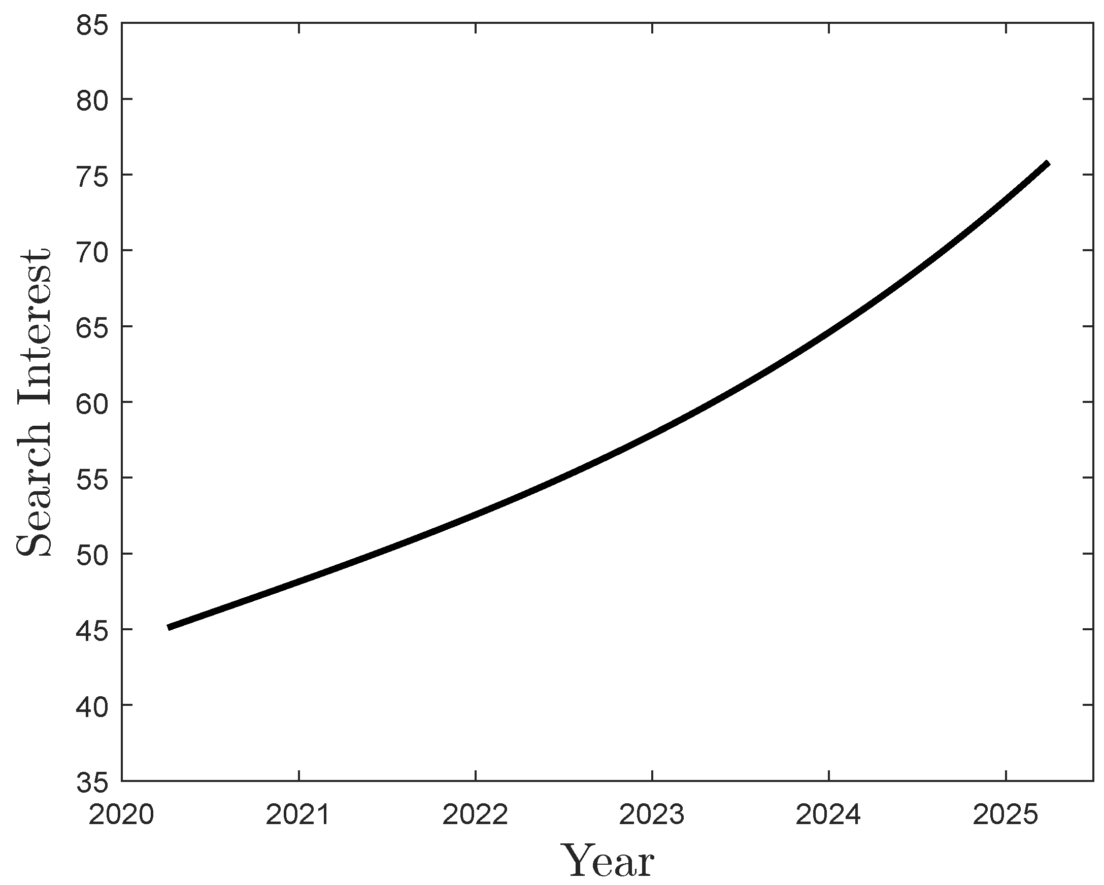
Figure 1. Google search interest over year for the keyword ”unmanned ground vehicle”.
Machines 13 01071 g001
Figure 2. Electric Dog [42].
Machines 13 01071 g002
Figure 3. Packbot510 [66].
Machines 13 01071 g003
Figure 4. Mars Exploration Rover Opportunity [68].
Machines 13 01071 g004
Figure 5. Scientific publications on unmanned ground vehicles between 2005 and 2024.
Machines 13 01071 g005
Figure 6. Systematic literature review methodology: PRISMA flow diagram.
Machines 13 01071 g006
Figure 7. Production of the top 10 authors over time. TC: Total Citations.
Machines 13 01071 g007
Figure 8. The conceptual structure map was created with the MCA algorithm and the K-Means clustering algorithm. The abscissa and ordinate are named as “Dim 1 (35.4%)” and “Dim 2 (17.01%)”, respectively.
Machines 13 01071 g008
Figure 9. Authors’ collaboration network.
Machines 13 01071 g009
Figure 10. Different types of wheels analyzed in this study. (a) Standard wheel. (b) Wheel caster. (c) Solid tires. (d) Airless tire. (e) Mecanum wheel. (f) Morphing wheel [96].
Machines 13 01071 g010
Figure 11. Robot explorer [99].
Machines 13 01071 g011
Figure 12. Omnidirectional tracks [115].
Machines 13 01071 g012
Figure 13. Continuous tracks.
Machines 13 01071 g013
Figure 14. Triangular track.
Machines 13 01071 g014
Figure 15. Terrain interaction of wheeled and tracked mobility systems.
Machines 13 01071 g015
Figure 16. Hardware architecture 1.
Machines 13 01071 g016
Figure 17. Hardware architecture 2.
Machines 13 01071 g017
Figure 18. Hardware architecture 3.
Machines 13 01071 g018
Figure 19. Hardware architecture 4.
Machines 13 01071 g019
Figure 20. Flow chart of the path planning and control process.
Machines 13 01071 g020
Figure 21. UGV for precision viticulture [190].
Machines 13 01071 g021
Figure 22. UGV producted by MILREM ROBOTICS [195].
Machines 13 01071 g022
Figure 23. Schematization of the forces acting on a tracked vehicle.
Machines 13 01071 g023
Figure 24. Example of a compound planetary gearing system serving as a mechanical reducer. The fundamental mechanical components that form the mechanism are the connecting components between the input and the output: a central pinion (a), a couple of first stage satellites (c′), a couple of second stage satellites (c″), a planet carrier (p), and a fixed planet gear (b).
Machines 13 01071 g024
Table 1. Main information about the reviewed documents.
Main Information About DataResults
Timespan2005:2024
Sources (Journals, Books, etc.)375
Documents581
Average years from publication8
Average citations per documents13.56
Table 2. General information on document types and their content.
Document TypesResults
article230
article; early access1
article; proceedings paper2
conference paper184
editorial material1
proceedings paper157
review6
Document contentsResults
Keywords Plus (ID)2593
Authors Keywords (DE)1623
Table 3. General information on authors and their collaborations.
AuthorResults
Total authors1998
Authors of single-authored documents6
Authors collaborationsResults
Single-authored documents6
Average number of Co-Authors per document4.08
Table 4. The top 10 most cited documents in the dataset.
Most Cited DocumentTotal CitationsTotal Citations per Year
TOKEKAR P, 2016, IEEE TRANS ROBOT [78]32432.40
LI J, 2016, IEEE TRANS VEH TECHNOL [79]19719.70
LATTANZI D, 2017, J INFRASTRUCT SYST [80]18620.67
CARLSON J, 2005, IEEE TRANS ROBOT [81]1788.48
YOON Y, 2009, CONTROL ENG PRACT [82]17710.41
LINDEMANN R, 2005, CONF PROC IEEE INT CONF SYST MAN CYBERN [67]1738.24
YU H, 2015, IEEE-ASME TRANS MECHATRON [83]16815.27
TOROK M, 2014, J COMPUT CIV ENG [84]16213.50
WONG J, 2006, J TERRAMECH [85]1477.35
QIN H, 2019, IEEE TRANS VEH TECHNOL [86]14320.43
Table 5. Power supply systems used in UGVs. Each system is evaluated based on its configuration, applications, advantages, and limitations.
Power Supply SystemCharacteristicsApplicationsAdvantagesLimitations
Internal combustion engine (ICE) + electric motor (EM)ICE drives an electric generator, while electric motors generate the vehicle motion.Military and security operations.Reduces power loss associated with mechanical transmission.Environmental issues, system complexity, and additional weight.
In-Wheel Motors (IWM)Each wheel is individually driven by an integrated motor.Military and security operations.Improved overall system efficiency and modularity.Low energy storage capacity; difficult power distribution among wheels; requires advanced control strategies.
Fuel cell + battery hybrid systemFuel cell serves as the primary power source, with batteries providing supplementary energy.Military and security operations.No restriction on charging, leading to longer system lifetime and improved reliability.High complexity, elevated cost, and hydrogen storage issues.
Table 6. Hardware systems used in UGVs. Each system is described by its characteristics, applications, advantages, and limitations.
Hardware SystemCharacteristicsApplicationsAdvantagesLimitations
NVIDIA Jetson NanoCompact and powerful embedded computer.Robotics, image classification, speech processing.Low cost and energy efficient.Limited computational power for high-end AI tasks.
NVIDIA Jetson TX2High-performance and power-efficient computing module.Manufacturing robots, drones, biomedical systems.Greater computing power and speed; suitable for complex algorithms.Higher cost compared to entry-level boards.
PixhawkCentral flight controller with multiple peripheral interfaces.Unmanned Aerial Vehicles (UAVs) and autonomous systems.Includes IMU, GPS, radio controller, and battery monitor.Limited CPU and memory; reduced processing capability.
Raspberry PiSingle-board computer with CPU, RAM, HDMI, USB, and wireless LAN.Automation, robotics, home servers, computer vision, and education.Low power consumption, affordable, compact design.Limited speed, I/O bandwidth, and networking performance in some models.
ArduinoMicrocontroller-based board with digital and analog I/O ports.Robotics, IoT, automation, and education.Low power consumption, cost-effective, easy to program.Limited memory, low computational capability, lacks real-time performance.
Table 7. Comparison of tracked and wheeled configurations. In this table, 1 represents the lowest rating, while 5 indicates the highest.
CriterionTrackedWheelsComments
Traction53Tracks offer superior traction, especially on low-cohesion surfaces.
Terrain adaptability52Tracks adapt better to uneven terrain, allowing them to overcome obstacles more easily.
Maneuverability43Both configurations are maneuverable, but the tracks can perform pivot turning.
Energy efficiency35Wheels are generally more energy efficient.
Speed on flat land35Wheels provide higher speeds on flat and firm surfaces.
Stability on slopes53Tracks ensure greater stability on slopes and slippery surfaces.
Ground pressure52The larger contact area of the tracks reduces sinking on soft terrain.
Mechanical robustness44Both systems can be designed to be robust.
Maintenance costs34Tracked systems require more frequent maintenance compared to wheels.
Initial cost35Wheeled configurations generally have lower production costs.
Total3836Overall score
Table 8. Main parameters used for the UGV sizing.
SymbolDescriptionValue (Units)
mMass of the UGV600 (kg)
vMaximum speed25 (km/h)
C r Rolling friction coefficient0.05 (−)
C d Drag coefficient0.8 (−)
AFrontal area0.88 (m2)
ρ Air density1.225 (kg/m3)
α Inclination angle0–30.96 (deg)
i = tan ( α ) · 100 Percentage slope0–60 (%)
η Efficiency of electric motor0.91 (−)
nNumber of motors2 (−)
Table 9. Required power at different road grades and corresponding velocities.
Percentage Slope (%)Required Power (W)Maximum Velocity (km/h)
01202.325
104431.425
204899.122
304839.416
404890.613
504868.011
604510.19
Table 10. Compound planetary gearing system parameters.
GearNumber of Teeth (-)Module (mm)Pitch Diameter (mm)
a161.2520
c′481.2560
c″201.0020
b1001.00100
Disclaimer/Publisher’s Note: The statements, opinions and data contained in all publications are solely those of the individual author(s) and contributor(s) and not of MDPI and/or the editor(s). MDPI and/or the editor(s) disclaim responsibility for any injury to people or property resulting from any ideas, methods, instructions or products referred to in the content.