1. Introduction
As core equipment in infrastructure construction, mining, and material handling, the level of intelligence and automation of construction machinery directly impacts operational efficiency, safety, and operator comfort. The loader, being one of the most widely used types of construction machinery, relies on its front working device to perform complex operations such as digging, lifting, and dumping. Achieving high-precision, high-dynamic trajectory tracking control of the working device’s end-effector is a key technology for enhancing the automation level of loaders. This advancement holds significant importance in reducing operator workload, improving operational accuracy and efficiency, and lowering energy consumption [
1].
The motion control of the working device is primarily realized through its hydraulic drive system. Electro-hydraulic proportional control systems have become the mainstream solution for modern construction machinery due to their advantages of high power density, fast response, relatively high control accuracy, and moderate cost [
2,
3,
4]. However, the loader working device is a typical multi-degree-of-freedom mechanical-hydraulic system characterized by strong nonlinearity, strong coupling, time-varying behavior, and complex external load disturbances. Its dynamic performance is significantly affected by various factors, including the nonlinearity of hydraulic valves, friction in hydraulic cylinders, oil compressibility, load mass variations, and system parameter uncertainties [
5,
6]. These inherent complexities make it difficult for traditional linear control theory-based methods to achieve satisfactory trajectory tracking performance. Particularly when dealing with large-range motions, abrupt load changes, and system parameter perturbations, issues such as increased tracking errors, response lag, and even instability are prone to occur [
7].
To address these challenges, numerous advanced control strategies have been introduced into the field of electro-hydraulic proportional control for construction machinery in recent years. For instance, sliding mode control has attracted attention due to its strong robustness, but its inherent chattering phenomenon may exacerbate system wear and compromise control precision [
8,
9,
10]. While particle swarm optimization and genetic algorithms have been employed to optimize PID parameters, thereby improving parameter self-adaptability, their effectiveness in compensating for the strongly coupled dynamics of hydraulic systems remains limited [
11]. Model predictive control predicts system behavior through rolling optimization and feedback correction, yet this method relies on an accurate system model and entails substantial online computational burden [
12]. Fuzzy control and neural network control do not require precise models but typically demand extensive empirical knowledge or training data [
13,
14].
As a systematic nonlinear controller design approach, backstepping is particularly suitable for cascade system control due to its structured design process and effective handling of system nonlinearities [
15]. The integration of adaptive mechanisms with backstepping, forming the adaptive backstepping control approach, enables simultaneous treatment of system nonlinearities and parameter uncertainties, thereby significantly enhancing both tracking performance and system robustness [
16,
17,
18]. Although the adaptive backstepping algorithm has demonstrated remarkable success in fields such as robotics and aerospace [
19,
20,
21], its in-depth theoretical research, tailored design, and comprehensive experimental validation remain relatively scarce for trajectory tracking control in complex electro-hydraulic systems like loader working devices, which exhibit unique load characteristics and strong nonlinearities.
Building upon the aforementioned background and analysis, this paper focuses on the high-performance trajectory tracking control problem of loader working devices, proposing a novel control strategy based on an adaptive backstepping algorithm. The main contributions and innovations of this study are manifested in the following aspects:
(1) High-fidelity system modeling: Unlike simplified models commonly used in prior studies, this work establishes a comprehensive fifth-order nonlinear state-space model that explicitly incorporates the dynamics of the electro-hydraulic proportional pressure-reducing valve and the hydraulic control directional valve. This model more accurately captures the high-frequency characteristics and nonlinearities inherent in the loader’s electro-hydraulic system.
(2) Loader-specific adaptive backstepping controller design: A trajectory tracking controller based on the adaptive backstepping algorithm is developed. Its innovation lies in the tailored design of adaptive laws that simultaneously estimate multiple critical time-varying parameters (e.g., viscous damping coefficient, leakage coefficient, load spring stiffness, bulk modulus, directional valve gain, and external load force) unique to the complex operating conditions of loaders. This multi-parameter online estimation provides robust compensation for system uncertainties.
(3) Comprehensive experimental validation: The proposed control strategy is implemented on a rapid-control-prototyping platform and validated through extensive experiments on a real-world loader working device. The performance is rigorously compared against a classical PID controller, quantitatively demonstrating significant improvements in trajectory tracking accuracy under realistic load variations.
The remainder of this paper is organized as follows:
Section 2 details the working principle of the electro-hydraulic proportional control system for loader working devices;
Section 3 establishes the nonlinear mathematical model of the system;
Section 4 presents the trajectory tracking controller design method based on the adaptive backstepping algorithm;
Section 5 demonstrates the experimental platform setup and provides detailed results analysis and discussion; finally,
Section 6 summarizes the key findings.
2. Working Principle
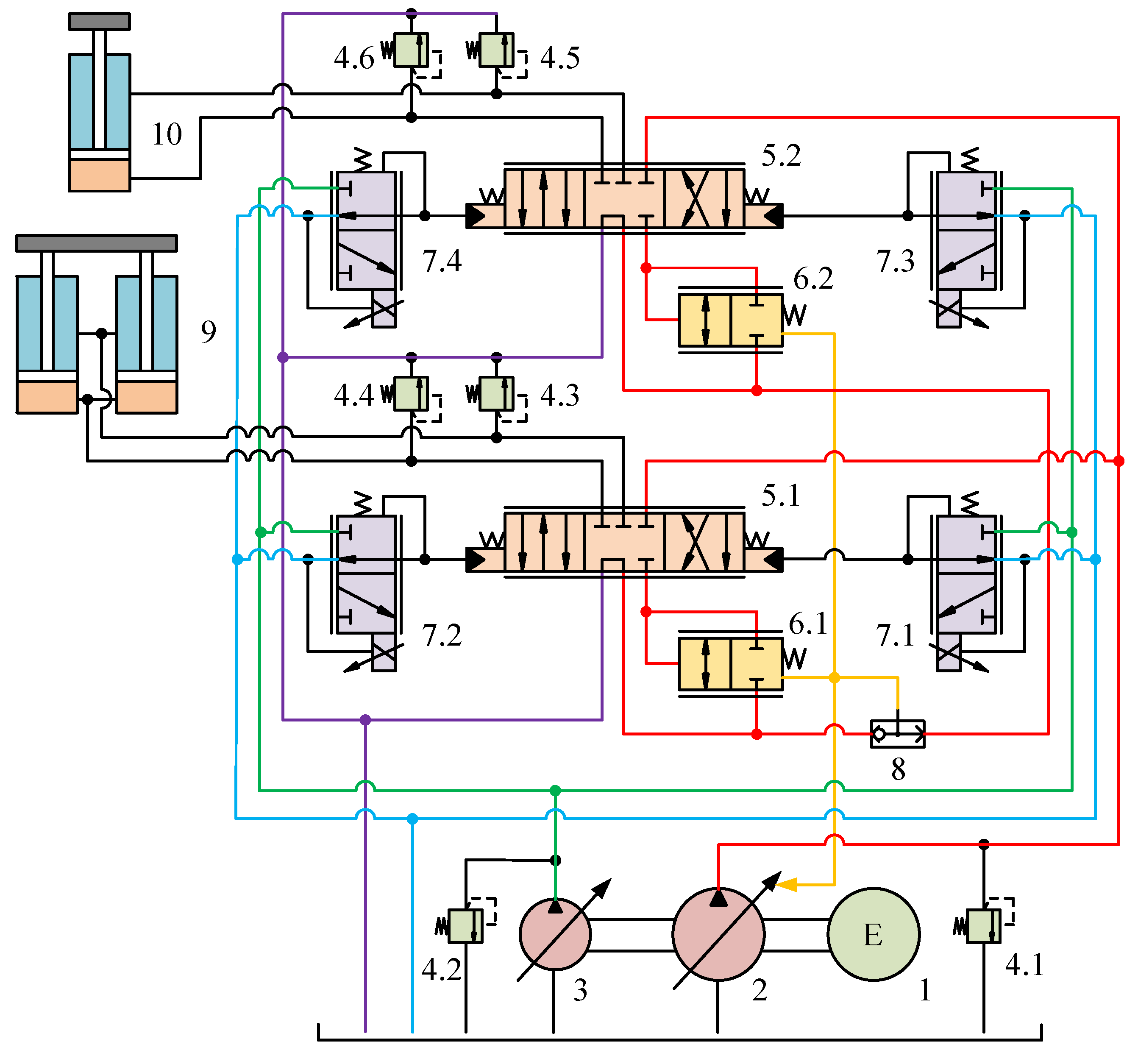
Figure 1 shows the hydraulic schematic diagram of the loader working device. The engine (1) coaxially drives a load-sensing pump (2) and a constant-pressure variable displacement pump (3). The load-sensing pump serves as the main oil supply unit of the system, automatically adjusting its output pressure and flow rate according to the actual working conditions, enabling adaptive matching of power to the load and helping to reduce system energy consumption. The constant-pressure variable displacement pump provides a stable pilot control oil source for the system. The high-pressure oil delivered by the load-sensing pump is distributed to the boom hydraulic cylinder (9) and the bucket hydraulic cylinder (10) after passing through the hydraulic control directional valves (5.1, 5.2) and pressure compensation valves (6.1, 6.2), thereby providing power support for the working device. The multiple relief valves (4.1~4.6) in the system are used to limit the maximum pressure in different circuits, ensuring system safety.
Electro-hydraulic proportional control is the core for achieving precise displacement tracking of the hydraulic cylinders. The pilot oil pressure output by the constant-pressure variable displacement pump is precisely regulated by the electro-proportional pressure-reducing valves (7.1~7.4). These pressure-reducing valves receive electrical command signals from the controller and convert them into corresponding hydraulic control pressures. This pressure acts on the spool control ends of the hydraulic control directional valves, thereby precisely controlling the spool displacement. By adjusting the spool displacement, the flow rate entering the hydraulic cylinders can be accurately controlled, ultimately regulating the motion speed and direction of the cylinders. The pressure compensation valves (6.1, 6.2) are used to maintain a constant pressure differential across the orifices of the hydraulic control directional valves. This ensures that the flow rate through the valve orifices is solely related to the spool opening and remains unaffected by fluctuations in load pressure, thereby improving the control precision of the system. The shuttle valve (8) selects the higher load pressure between the boom cylinder and the bucket cylinder and feeds it back to the displacement mechanism of the load-sensing pump, ensuring the pump’s output pressure consistently adapts to the highest load pressure.
During the loader’s digging operation, the motion control of the working mechanism is achieved through coordinated operation of the boom system and bucket system. The movement trajectory of the working mechanism is typically represented by the bucket tip trajectory. Therefore, based on the optimally planned motion trajectory of the bucket tip, the ideal displacement trajectories of both the boom hydraulic cylinder and bucket hydraulic cylinder can be calculated.
Both the boom and bucket systems employ electro-hydraulic proportional control technology for precise regulation.
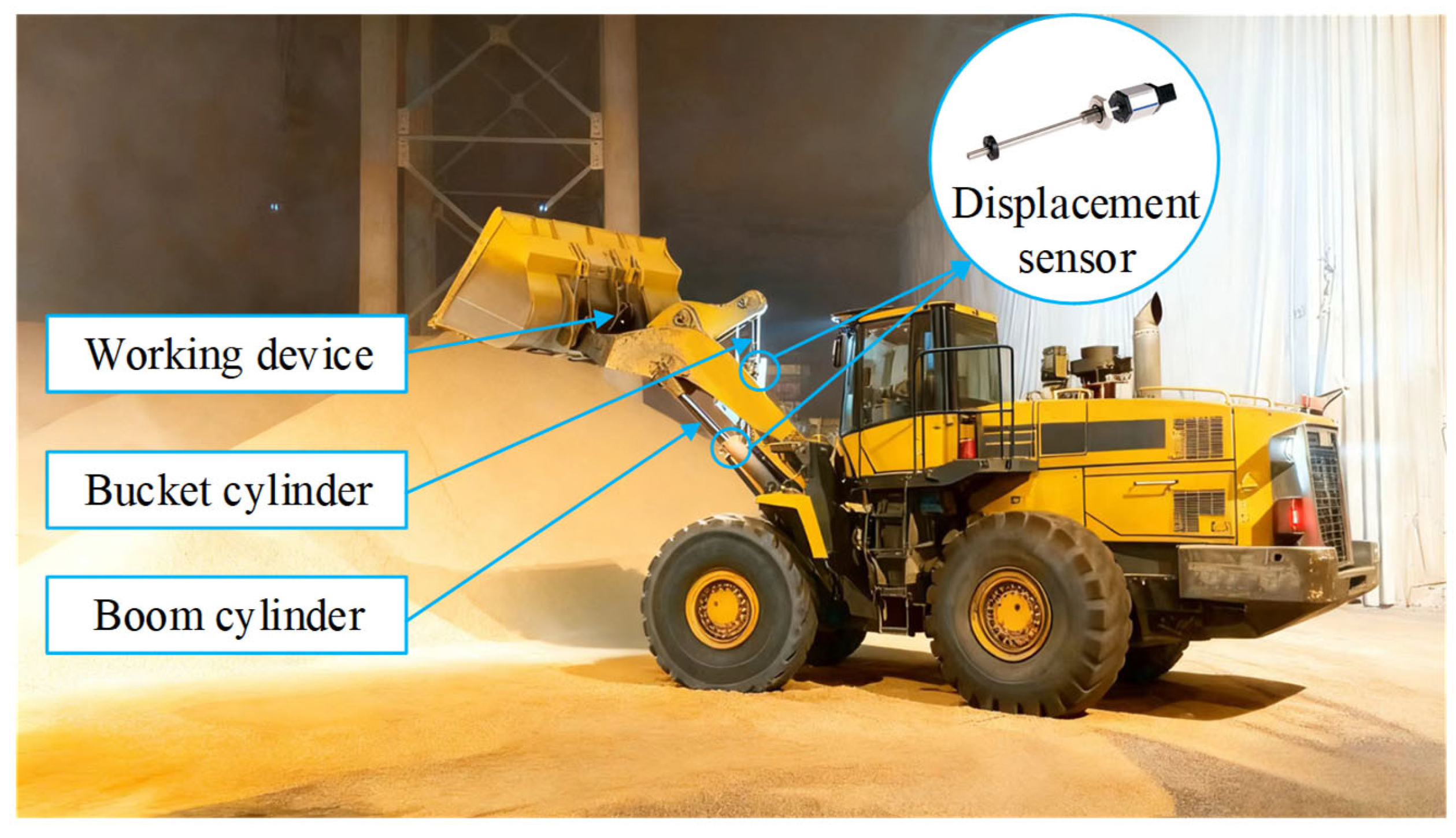
Figure 2 illustrates the complete control process. Displacement sensors continuously monitor the hydraulic cylinder positions, comparing them with desired displacements to generate error signals that are fed into the controller. After processing, the controller outputs precise voltage command signals, which are converted and amplified by proportional amplifiers to drive the electro-proportional pressure reducing valves. The pressure-reducing valves, responding to input currents, deliver control oil at corresponding pressures to adjust the spool displacement of the hydraulic control directional valves. This precisely regulates the hydraulic oil flow rate, ultimately achieving closed-loop control of the hydraulic cylinder displacements. Through accurate position control of both the boom and bucket hydraulic cylinders, the bucket tip can closely follow the predetermined motion trajectory with high precision.
4. Control Strategy
The block diagram of the trajectory tracking control based on the adaptive backstepping algorithm is illustrated in
Figure 4. The mathematical model of the electro-hydraulic proportional system is decomposed into a sequence of subsystems in strict feedback form. Using a recursive design approach, the virtual control law is systematically derived starting from the hydraulic cylinder displacement tracking error. Parameter adaptation laws are introduced to estimate unknown system parameters online, while Lyapunov functions are constructed to ensure the stability of each subsystem. Ultimately, the actual control input signal is synthesized to drive the hydraulic cylinder’s actual displacement to asymptotically converge to the desired displacement.
Considering that both the proportional amplifier and electro-proportional pressure reducing valve exhibit proportional characteristics, the system’s input control voltage and the output pressure of the pressure reducing valve maintain a linear relationship. Therefore, this study selects the output pressure
of the pressure-reducing valve as the system’s control variable. The system state variables are defined as: hydraulic cylinder displacement
, hydraulic cylinder velocity
, load pressure
, spool displacement of the directional valve
, and spool velocity of the directional valve
. Letting the state vector
, the state-space equation of the system is obtained as:
where
,
,
,
,
,
,
,
,
, and
.
During actual loader operations, due to complex and variable working environments, dynamically changing load conditions, and inherent hydraulic system characteristics, key system parameters often exhibit significant time-varying properties. These include the viscous damping coefficient of the hydraulic cylinder, leakage coefficient of the hydraulic cylinder, load spring stiffness, bulk modulus of the hydraulic oil, gain coefficient of the directional valve, viscous damping coefficient of the directional valve, and external load force. Accordingly, in establishing the state-space equations, terms containing these unknown parameters are defined as time-varying unknown quantities, including , , , , , and .
The step-by-step design procedure for the trajectory tracking controller based on the adaptive backstepping algorithm is presented as follows:
Define the error equations for each subsystem as:
where
is the desired displacement of the hydraulic cylinder,
is the virtual control variables for subsystems.
Step 1: For the first subsystem
The derivative of
is obtained as:
Define the Lyapunov function for the first subsystem as:
The derivative of
yields:
Define the virtual control variable
for the first subsystem as:
Further derivation gives:
Step 2: For the second subsystem
The derivative of
is obtained as:
Define the estimation errors for
,
and
as:
where
is the true values of the uncertain parameters,
is the estimated values of the uncertain parameters.
Define the Lyapunov function for the second subsystem as:
The derivative of
yields:
To eliminate
,
and
, let:
Define the virtual control variable
for the second subsystem as:
Substituting Equations (27) and (28) into Equation (26) yields:
Step 3: For the third subsystem
The derivative of
is obtained as:
Define the estimation errors for
,
and
as:
Define the Lyapunov function for the third subsystem as:
The derivative of
yields:
To eliminate
,
and
, let:
Define the virtual control variable
for the third subsystem as:
Substituting Equations (34) and (35) into Equation (33) yields:
Step 4: For the fourth subsystem
The derivative of
is obtained as:
Define the Lyapunov function for the fourth subsystem as:
The derivative of
yields:
Define the virtual control variable
for the fourth subsystem as:
Further derivation gives:
Step 5: For the fifth subsystem
The derivative of
is obtained as:
Define the estimation error for
as:
Define the Lyapunov function for the fifth subsystem as:
The derivative of
yields:
Define the control variable
of the adaptive backstepping controller as:
Substituting Equations (46) and (47) into Equation (45) yields:
where
is the backstepping coefficient of the controller, and
.
The adaptive laws in Equations (27), (34) and (46) are modified with a projection operator to ensure parameter boundedness. The closed-loop system is uniformly ultimately bounded, and the tracking error converges to a small residual set.
The global asymptotic stability of the closed-loop system is guaranteed by the Lyapunov stability theory. Consider the final composite Lyapunov function candidate for the entire system:
The derivative of
V along the trajectories of the system is:
Substituting the error dynamics, the virtual control laws (Equations (21), (28), (35) and (40)), the actual control law (Equation (47)), and the parameter adaptation laws (Equations (27), (34) and (46)), it can be rigorously derived that:
Since V is positive definite and is negative semi-definite, V is bounded, which implies that all error signals and parameter estimation errors are bounded. Furthermore, from Barbălat’s lemma, it can be concluded that the tracking errors asymptotically converge to zero as time increases. Therefore, the global asymptotic stability of the system is ensured.
In conclusion, when the electro-hydraulic proportional control system of the loader working device adopts the control law shown in Equation (47), combined with the parameter adaptation laws designed in Equations (27), (34), and (46), it ensures that the final position tracking error of the electro-hydraulic proportional control system asymptotically converges to zero.
6. Conclusions
This study proposes and validates an adaptive backstepping control strategy to address the high-precision trajectory tracking requirements of loader working devices under strong nonlinearities, parameter uncertainties, and external load disturbances. Through systematic theoretical analysis, controller design, and experimental investigation, the following conclusions are drawn:
(1) The designed adaptive backstepping tracking controller guarantees global asymptotic stability of the closed-loop system via Lyapunov stability theory, while incorporating adaptive laws for real-time online estimation of key uncertain parameters. This significantly enhances robustness against parameter variations and external disturbances.
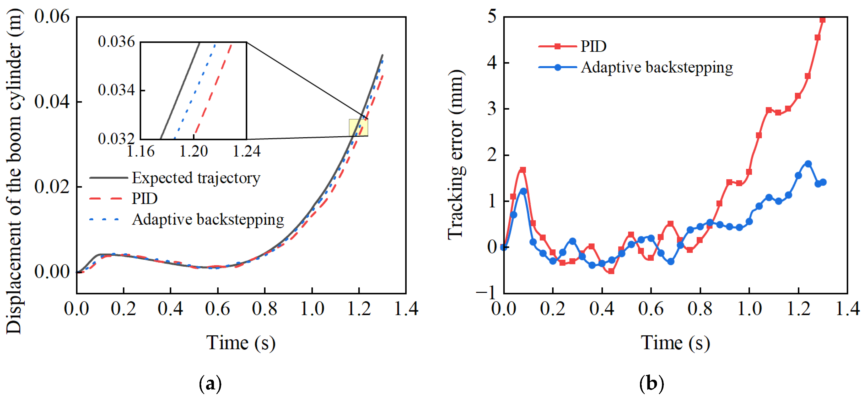
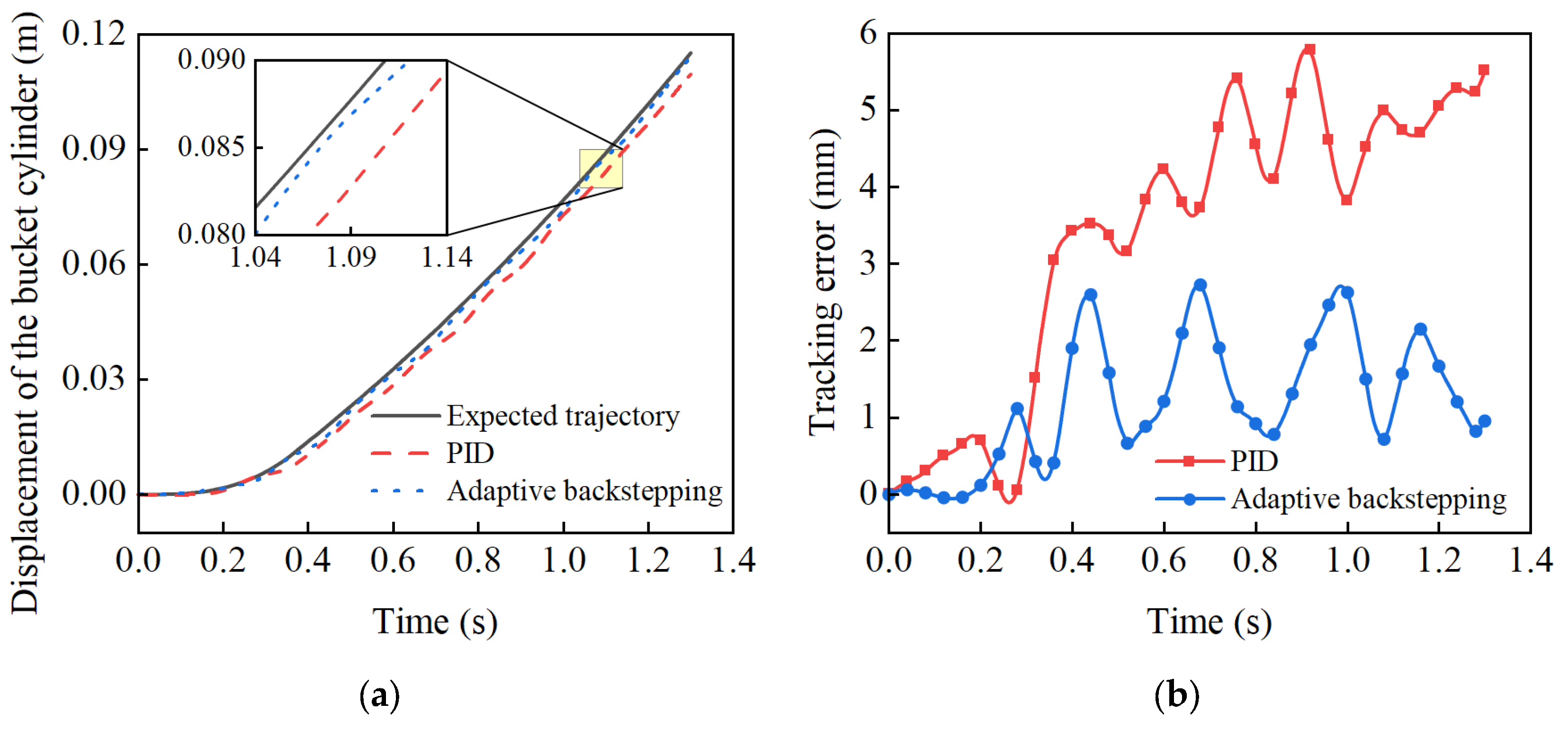
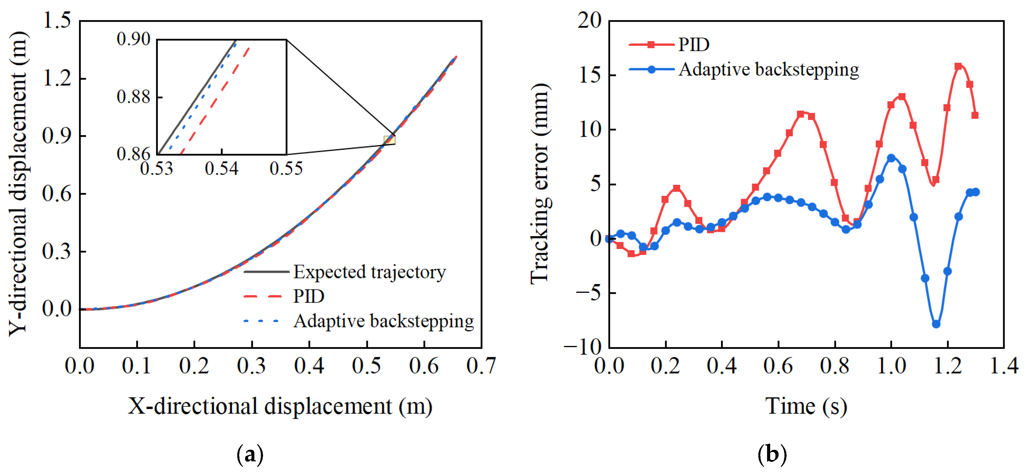
(2) The experimental results based on a representative mining trajectory show that, compared with classical PID control, the proposed method reduced the maximum tracking error and the RMSE for the boom cylinder by 63.08% and 57.98%, and for the bucket cylinder by 53.18% and 62.14%, respectively. Most importantly, for the critical bucket tip trajectory, the corresponding improvements reached 50.88% and 56.07%,conclusively demonstrating its superior performance in improving trajectory tracking accuracy.
The proposed adaptive backstepping control strategy shows promise in improving trajectory tracking accuracy for loader electro-hydraulic systems. The methodological framework can serve as a reference for intelligent control of similar construction machinery. Future research will focus on embedded real-time algorithm optimization and integration with intelligent control methods.
