Abstract
To address the difficulty of directly detecting internal stresses in high-temperature forgings during dual-manipulator control experiments and the significant safety risks associated with high-temperature environments, this study developed an experimental device to simulate the deformation behavior of such forgings. First, numerical simulations of the elongation process were conducted using DEFORM V11 software to examine the deformation mechanisms of high-temperature forgings. Quantitative results for axial deformation, maximum deformation velocity, and deformation force ranges were obtained, which defined the operational specifications and functional requirements of the device. Second, the mechanical structure and hydraulic system were designed based on engineering principles. The dynamic response characteristics of the simulation device under conventional PID and fuzzy PID control were compared through simulations, and the feasibility of the fuzzy PID control strategy was experimentally verified. Finally, a joint simulation model of the high-temperature forging deformation simulation device and the dual forging manipulator clamping system was established. This model was used to analyze the dynamic response of the simulated workpiece under typical cooperative conditions of dual manipulators and to assess the accuracy of the simulation process during clamping. The results confirmed the practical applicability of the device. Overall, the developed simulation device can effectively reproduce the deformation behavior of high-temperature forgings under ambient conditions, providing a safe and reliable platform for studying coordinated control strategies of dual forging manipulators.
1. Introduction
With the rapid advancement of industries such as shipbuilding, aerospace, and wind energy, the production of large-scale shaft forgings is subject to increasingly stringent requirements for efficiency and quality [1,2]. In the forging process, clamping methods are primarily classified into single-manipulator and dual-manipulator modes. Compared with the single-manipulator approach, dual-manipulator coordinated clamping mitigates the cantilever effect, improves load-bearing capacity, and enhances operational continuity, thereby significantly increasing forming efficiency [3,4,5]. However, due to the unpredictable deformation at both ends of the forging during processing, achieving coordinated control with dual manipulators is considerably more complex than with a single manipulator. At present, mature control strategies are lacking, and most current methods rely heavily on empirical experimentation [6,7,8]. These experimental approaches, however, present notable challenges, including difficulties in measuring internal forces, significant safety risks, and high material costs-highlighting the pressing need for a safer and more efficient alternative.
To deepen the understanding of forging behavior, particularly in titanium alloys, extensive research has been conducted both domestically and internationally. Kukuryk [9] systematically analyzed the hot forging process of Ti-6Al-4V alloy, identifying three typical metal flow patterns and the evolution of thermal phenomena. Liu and Baker [10] developed a constitutive model for the isothermal forging of IMI685 titanium alloy based on experimental investigations. Alimov et al. [11], Wu and Pang [12] utilized numerical simulations to explore the microstructural evolution and forming mechanisms during the hot forging of titanium alloys. Fang X. et al. [13] systematically studied the non-isothermal creep deformation behavior of TC4 titanium alloy and proposed optimal process parameters corresponding to its creep characteristics. Chen Y. et al. [14], through tensile testing, observed that the strength of TC4 and TC17 forgings increases with strain rate, while elongation decreases. Collectively, these studies have established a solid foundation for understanding the deformation behavior of titanium alloy forgings.
Meanwhile, simulation technologies for the forging process have seen significant advancements. Kim B. T. et al. [15] employed the finite volume method to simulate the forging compression process, confirming its applicability to complex hot forging operations and providing a theoretical basis for the design of forging simulators. Zhang P. et al. [16] analyzed the compliant motion of forging manipulators and proposed a two-degree-of-freedom parallel mechanism to simulate workpiece loading conditions, enabling assessment of the manipulator’s load-bearing capacity. Im et al. [17] developed a cold heading forging design system for spherical joints by integrating forging simulators with computer-aided process technologies, thereby enhancing the efficiency of process design. However, existing studies have primarily focused on auxiliary simulations of forging equipment, while simulation devices and technologies specifically designed to address the collaborative control requirements of manipulators—aimed at accurately replicating the dynamic deformation behavior of the forging workpiece—remain largely unexplored.
To address the challenges posed by unpredictable deformation and the inability to directly measure internal forces in high-temperature forgings, this study presents the development of a high-temperature forging deformation simulation device (HTFDSD). The device is designed to replicate the deformation behavior of forgings under ambient conditions, thereby serving as a surrogate for high-temperature forgings in dual-manipulator forging simulation experiments. This solution is expected to provide a reliable experimental platform for advancing coordinated control strategies in dual forging manipulator systems.
2. Analysis of Boundary Conditions in HTFDSD Design
2.1. Functional Requirements Analysis of HTFDSD
Figure 1 illustrates the deformation behavior of the forging during the elongation process under the dual forging manipulator mode. At this stage, the forging experiences deformation in three directions due to the action of the press: axial elongation, lateral spreading, and vertical upsetting. Among these, axial elongation results in positional coupling with the grippers of the manipulators on both sides, generating significant reaction forces that can compromise forming quality. Vertical upsetting lowers the central axis of the forging, necessitating a reduction in the clamping height of the manipulators to prevent gripper detachment or instability in the clamping system. In contrast, lateral spreading has minimal impact on the manipulators’ operation and can therefore be disregarded. Consequently, HTFDSD must be capable of reproducing the axial elongation and vertical upsetting behavior of the forging. Since vertical deformation is predominantly governed by the press anvil—with its deformation velocity and displacement synchronized with the anvil—the study primarily concentrates on the characteristics of axial deformation.
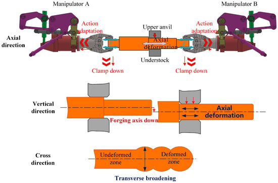
Figure 1.
Schematic of forging deformation in the elongation step with dual manipulators.
2.2. Influence of Various Factors on the Axial Deformation Behavior of Forgings
The deformation behavior of forgings is affected by several key factors, including the reduction ratio, the anvil-to-forging width ratio, the forging speed of the press, the initial forging temperature, and the feed rate. To investigate their effects, a simulation model was established using DEFORM software to analyze the influence of each parameter on forging deformation, thereby providing a theoretical basis for the design of the HTFDSD.
The HTFDSD was designed based on the “5 MN Fast Forging Hydraulic Press-Dual Manipulator Pilot Platform” at Yanshan University. Through analysis of the press and manipulator dimensions and load-bearing capacities, the maximum cross-sectional diameter of the simulated forging was set at 400 mm, with a length of 1500 mm. A corresponding simulation model was then developed, as illustrated in Figure 2. For clarity in subsequent discussions, the positive direction of the z-axis is defined as leftward, and the negative direction as rightward.
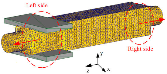
Figure 2.
Elongation simulation model of forgings.
The simulation employs the widely used Wide Die Heavy Blow Forging (WHF) method, which typically involves a blank width ratio between 0.5 and 0.8 and a reduction ratio greater than 20%. Titanium alloys such as TC4 and TC6 are selected as the simulated materials, with the initial forging temperature ranging from 850 °C to 1000 °C.
A finite element model was developed using DEFORM V11 software. The billet was meshed into approximately 15,000 tetrahedral elements, with local mesh refinement applied to enhance accuracy in the contact regions. A thermo-mechanically coupled analysis was performed to simultaneously compute deformation and heat transfer. The high-temperature rheological behavior of the titanium alloy was characterized using the Arrhenius constitutive model, with parameters determined from published experimental data within the corresponding temperature range. Friction between the billet and dies was modeled using a shear friction law with a friction factor of 0.7. A sparse matrix solver was employed, and the force convergence criterion was set to 0.1. The basic boundary condition parameters used in the simulation are summarized in Table 1.
Based on this model, the effects of various process parameters on the deformation behavior of the forging were systematically investigated, revealing their underlying influence mechanisms.

Table 1.
The fundamental parameters of the simulation boundary conditions.
Table 1.
The fundamental parameters of the simulation boundary conditions.
| Initial Forging Temperature | Blank Width Ratio | Forging Speed | Friction Factor | Reduction Ratio |
|---|---|---|---|---|
| 850 °C | 0.6 | 40 mm/s | 0.6 | 20% |
2.2.1. Effect of Reduction Ratio on the Axial Deformation of Forgings
Figure 3 illustrates the effect of a reduction ratio ranging from 20% to 30% on the axial deformation and peak deformation velocity of the forging. As shown in Figure 3a, increasing the reduction ratio from 20% to 30% results in an increase in axial elongation from 56.3 mm to 77.4 mm. Based on the principle of volume constancy during deformation, the deformation volume increases with the expansion of the deformation zone, and the elongation demonstrates an approximately linear relationship with the reduction ratio. Figure 3b shows that, as the reduction ratio increases, the maximum axial deformation velocity on the left side rises from 15.6 mm/s to 17.9 mm/s, while on the right side it increases from −14.3 mm/s to −15.9 mm/s. Although the deformation velocity exhibits a slight increase, the overall variation remains limited. The simulation results suggest that the reduction ratio has a minor effect on the peak deformation velocity during elongation, with the maximum single-pass elongation reaching approximately 77.4 mm and the peak deformation velocity around 18 mm/s.
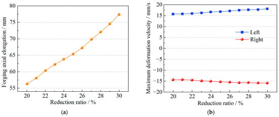
Figure 3.
Variation in axial deformation of forgings under different reduction ratios. (a) Effect of reduction ratio on forging axial elongation. (b) Effect of reduction ratio on forging deformation velocity.
2.2.2. Effect of Blank Width Ratio on the Axial Deformation of Forgings
Figure 4 presents the axial deformation behavior of the forging under identical conditions with a blank width ratio ranging from 0.6 to 0.8. As shown in Figure 4a, the influence of the anvil width ratio on axial elongation is modulated by the reduction ratio. When the reduction ratio is below 24%, its effect is negligible. However, when the reduction ratio increases to 30%, the axial elongation difference between the maximum and minimum anvil width ratios reaches 2.3 mm, indicating that the deformation shifts more prominently in the horizontal direction, with a maximum elongation of 72.2 mm. Figure 4b shows that, at a fixed reduction ratio of 20% and a blank width ratio between 0.6 and 0.8, the variation in maximum axial deformation velocity on both sides of the forging is approximately 2 mm/s, with a peak value of 16.1 mm/s. This suggests that the anvil width ratio has little effect on deformation velocity. The simulation results indicate that employing a lower reduction ratio enhances the accuracy of deformation simulation.
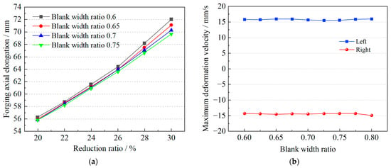
Figure 4.
Variation in axial deformation of forgings under different blank width ratios. (a) Effect of blank width ratio on forging axial elongation. (b) Effect of blank width ratio on forging deformation velocity.
2.2.3. Effect of Initial Forging Temperature on the Axial Deformation of Forgings
The simulation was performed at four commonly used forging temperatures—850 °C, 900 °C, 950 °C, and 1000 °C—uniformly distributed within the 850–1000 °C range. The effect of temperature on forging deformation is illustrated in Figure 5. As shown in Figure 5a, the axial elongation of the forging remains nearly constant across the temperature range, suggesting that the initial temperature has a minimal effect. This is because, although elevated temperatures enhance metal plasticity, the deformation is primarily governed by the volume of the deforming body; under constant volume, temperature has little influence on elongation. Figure 5b indicates that the maximum axial deformation velocity varies by no more than 2 mm/s within the temperature range, showing no significant correlation with temperature. The most notable influence of temperature is observed in the deformation force, as shown in Figure 5c. With increasing temperature, the internal deformation force decreases substantially, with the maximum value reduced to approximately 28 tons, leading to more uniform material flow. For forging presses, elevated temperatures lower deformation resistance and reduce load requirements. For the design of HTFDSD, it is recommended to adopt 30 tons as the maximum initial parameter to ensure a sufficient safety margin.
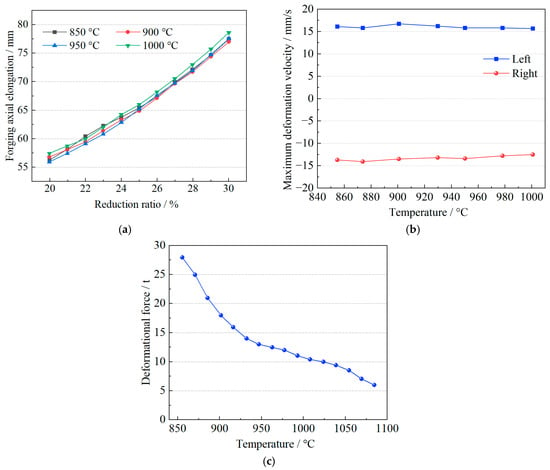
Figure 5.
Effect of initial forging temperature on the axial deformation behavior of the forging. (a) Effect of temperature on forging axial elongation. (b) Effect of temperature on forging deformation velocity. (c) Effect of temperature on the deformation force of the forging.
2.2.4. Effect of Friction Factor on the Axial Deformation of Forgings
Friction plays a critical role in influencing material flow behavior during the forging process. A friction factor that is too low may result in relative sliding between the forging and the die surface, while an excessively high value can cause sticking between the material and the die. In the simulation, the friction factor was set between 0.4 and 0.6 to examine its effect on the axial deformation of the forging, as shown in Figure 6. When the reduction ratio was between 20% and 30%, the elongation remained largely unchanged, with only slight fluctuations observed between 21% and 25%. This is because friction primarily affects the deformation resistance in the contact region between the forging and the die, whereas the main deformation occurs in the internal, non-contact region, where the stress distribution remains relatively uniform and axial material flow is minimally affected. Therefore, variations in the friction factor have little influence on the forging’s elongation or its maximum deformation velocity.
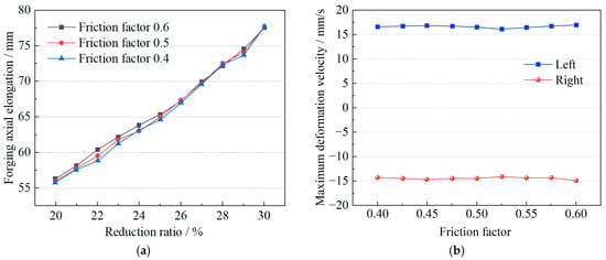
Figure 6.
Effect of friction factor on the axial deformation behavior of the forging. (a) Effect of friction factor on forging axial elongation. (b) Effect of friction factor on forging deformation velocity.
2.2.5. Effect of Forging Speed on the Axial Deformation of Forgings
Forging speed refers to the rate at which the press drives the die during the forging process. It significantly influences the internal metal flow within the workpiece. At low forging speeds, deformation is generally uniform, but rapid heat dissipation may lead to hardening. Conversely, high forging speeds can result in insufficient deformation, potentially causing folding or cracking. Therefore, it is essential to perform simulation analyses of the deformation behavior of the workpiece under varying forging speeds.
The effect of forging speed on the axial deformation of the workpiece is illustrated in Figure 7. Figure 7a shows that variations in forging speed within the 20% to 32% range have a negligible effect on axial elongation. However, Figure 7b demonstrates that as the forging speed increases from 16 mm/s to 40 mm/s, the maximum axial deformation velocity on the left side of the workpiece increases from 5 mm/s to approximately 15 mm/s, while on the right side it rises from 5 mm/s to around 13 mm/s. The trend is nearly linear, and the deformation velocities on both sides are comparable. These results indicate that increasing the forging speed significantly enhances material flow and produces a linear increase in deformation velocity. Therefore, during elongation simulations using a test device, the deformation velocity can be directly estimated based on the forging speed defined in the process parameters.
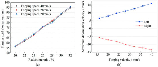
Figure 7.
Effect of forging speed on the axial deformation behavior of the forging. (a) Effect of forging speed on forging axial elongation. (b) Effect of forging speed on forging deformation velocity.
In summary, the reduction ratio, feed rate, and die width ratio significantly influence the elongation deformation of the forging, whereas the effects of initial temperature, friction factor, and forging speed are minimal and can be disregarded. Among these factors, the reduction ratio and feed rate exhibit an approximately linear relationship with elongation.
The differences in their influence mainly stem from the distinct roles these parameters play in the transmission of deformation energy. The reduction ratio, feed amount, and anvil width ratio directly determine the stress state and volume distribution within the core deformation zone of the forging, thereby exerting a dominant influence on elongation efficiency. In contrast, variations in initial temperature, friction coefficient, and forging speed within the conventional process window defined in this study have only a secondary effect on the total deformation energy and can therefore be considered less significant.
Accordingly, the design of the simulation device prioritizes high-precision and symmetrical coordinated control of the reduction ratio and feed amount—namely, the axial displacement and velocity—to accurately replicate the core elongation process. Meanwhile, secondary factors such as temperature and friction are treated as constant parameters in the simulator. This design strategy achieves an optimal balance between simulation fidelity and system complexity.
Based on these findings, the design requirements for HTFDSD are as follows:
- The device must be capable of simulating deformation in both the axial and vertical directions of the forging.
- The deformation magnitude and velocity on both sides of the forging are similar, indicating symmetric deformation. Therefore, during axial deformation simulation, the device should ensure synchronized and symmetric motion on both sides.
- The device must incorporate force feedback functionality to support coordinated control of dual manipulators in future applications.
3. Structure Design of HTFDSD
3.1. Structural Design of HTFDSD
HTFDSD was designed based on the “5 MN fast-forging hydraulic press–dual forging manipulator pilot platform” at Yanshan University. Within the dimensional constraints of the platform, the maximum distance between the clamps of the two manipulators is 2500 mm, and the maximum distance between the upper anvil plate and the lower anvil of the press is 800 mm. To allow sufficient space for installation and operation, the horizontal dimension of the device is limited to 2000 mm, while the vertical dimension is restricted to 700 mm. Figure 8 presents a schematic of the horizontal and vertical spatial clearances of the pilot platform.
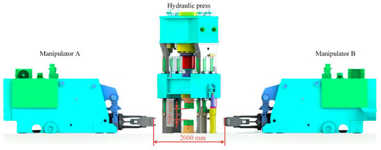
Figure 8.
A schematic diagram of the spatial distance of the pilot platform.
According to Figure 5, the deformation force required for the simulated workpiece is approximately 30 t, which is considerable. During subsequent clamping tests involving HTFDSD and dual manipulators, force coupling may also occur. Consequently, a hydraulic system is more suitable than a rigid mechanical device for performing the simulation. Based on the design requirements, the preliminary scheme of HTFDSD incorporates three hydraulic cylinders arranged in a T-shaped configuration. The structural schematic of HTFDSD is shown in Figure 9, comprising a base, hydraulic cylinders, connectors, detachable clamping ends, and sensors. The base is fixed to the lower anvil plate to ensure stability. The three hydraulic cylinders perform distinct functions: the two horizontal cylinders extend synchronously to simulate axial elongation, while the vertical cylinder adjusts the height to replicate changes in the workpiece axis. Pressure sensors are mounted at the ends of the piston rods to monitor clamping forces in real time, and displacement sensors are installed on the cylinders to precisely control piston strokes and record displacements. Closed-loop feedback ensures the accuracy of deformation simulation. The sensor system provides dual data support—force and displacement—for process optimization, ensuring that the overall design satisfies both functional requirements and experimental data acquisition needs.
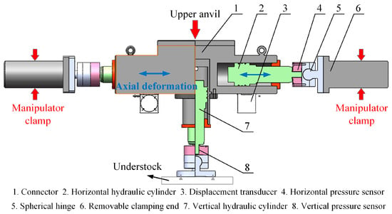
Figure 9.
Structure diagram of HTFDSD.
The strokes and dimensions of the three hydraulic cylinders are constrained by both the spatial limitations of the pilot platform and the deformation characteristics of the workpiece. Each horizontal cylinder has a stroke of 120 mm, while the vertical cylinder has a stroke of 100 mm. The maximum velocity of the horizontal cylinders is set at 50 mm/s, based on the results in Section 2, and the vertical cylinder’s velocity, restricted by the conditions of the pilot platform, is also limited to 50 mm/s.
For the clamping mechanism, detachable circular-section clamping ends are employed to facilitate material replacement and to investigate jaw engagement effects. Their dimensions are determined by the manipulator clamp size, with a diameter of 150 mm and a length of 300 mm. The connectors are fabricated from high-strength steel and sized to match the width of the upper anvil, preventing direct impact of the press on the hydraulic cylinders. This modular design ensures structural strength while improving experimental flexibility.
However, under real operating conditions, unbalanced coupling forces inevitably arise on both sides of HTFDSD due to factors such as manipulator response speed, inertial mass, and control precision. As illustrated in Figure 10, which shows the force distribution between HTFDSD and the clamps after the die is lifted, these coupling forces generate bending moments in both the horizontal and vertical directions. Such bending moments may result in uneven loading, wear, or structural damage to the hydraulic cylinders, ultimately reducing the service life of HTFDSD.
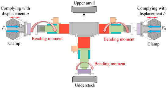
Figure 10.
Schematic diagram of the bending moment acting on HTFDSD.
Based on the force analysis under the previously described clamping conditions, HTFDSD was improved. The device incorporates three spherical hinge mechanisms, linking the horizontal pressure sensors to the detachable clamping ends and the vertical pressure sensors to the base. After lifting the upper anvil, rotational movement between the spherical hinge components releases bending moments, thereby ensuring system safety.
Each spherical hinge consists primarily of a ball and a socket. The commonly used material is GCr15, which has an allowable stress of approximately 10 GPa, a Poisson’s ratio of 0.3, and an elastic modulus of 210 GPa. The maximum load of the hydraulic cylinder is 30 t. According to Hertz contact theory, the contact stress between the ball and socket must not exceed the material’s allowable stress. The ball radius is calculated using the following formula:
where σmax is the allowable stress (GPa); r is the radius of the ball (mm); and E is the equivalent elastic modulus (GPa).
Substituting the data yields a ball radius of 261 mm. The maximum swing angle of the spherical hinge is designed to be 10°. Using Equation (2), the radius of the socket is calculated to be 305 mm.
where θ is the maximum deflection angle and R is the radius of the socket (mm).
To implement the proposed design, the spherical hinge was fabricated using custom-made components instead of standard parts to ensure precise compatibility with the device’s structural dimensions and load requirements. During manufacturing, both the ball head and the socket were produced from GCr15 bearing steel and subjected to quenching and tempering treatments to achieve high hardness and wear resistance. To guarantee smooth rotation of the ball head within the socket and reliable load-bearing performance, the mating surfaces were finely ground and polished to attain a low surface roughness. During assembly, a micron-level clearance was maintained between the ball head and the socket, and a high-performance lubricant was applied. This configuration not only enables flexible rotation within the designed swing angle of 10° but also prevents impact and positioning inaccuracies resulting from excessive clearance. The integration of this customized design with precision manufacturing and assembly processes ensures the spherical hinge’s feasibility and reliability in practical applications.
The physical prototype of HTFDSD is shown in Figure 11. And the mechanical design parameters of HTFDSD are listed in Table 2.
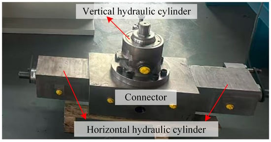
Figure 11.
The physical prototype of HTFDSD.

Table 2.
The mechanical design parameters of HTFDSD.
3.2. Design of the Hydraulic System for HTFDSD
According to Table 2, the three hydraulic cylinders are designed with identical loads and a maximum velocity of 30 t and 50 mm/s, respectively, with strokes of 120 mm and 100 mm. To determine the basic parameters of the hydraulic system, a system pressure of 25 MPa, commonly used in engineering practice, was selected. Using Equations (3)–(5), the displacement, force, and velocity of the cylinders were substituted into the calculations, yielding the fundamental dimensional parameters of the three cylinders, as presented in Table 3.
where F represents the load force of the hydraulic cylinder (N); D is the rodless chamber diameter of the cylinder (mm); P is the system pressure (MPa); Q is the cylinder flow rate (L/min); A is the cross-sectional area of the rodless chamber (mm2); v is the piston velocity (mm/s); and d is the piston rod diameter (mm).

Table 3.
The dimension parameters of hydraulic cylinder.
To ensure the accuracy of HTFDSD, the horizontal hydraulic cylinders are controlled by proportional valves, with the horizontal and vertical cylinder circuits operated independently. The hydraulic schematic is shown in Figure 12, with a variable pump serving as the system’s power source. The vertical cylinder circuit is regulated via the 3.3 proportional directional valve. When this valve is in the right position, oil is supplied to both the accumulator and the vertical cylinder. Once the accumulator pressure reaches the load corresponding to its own weight, the vertical cylinder piston rod begins to extend. After full extension, the 3.3 proportional valve returns to the neutral position, placing the device in the pre-forging preparation stage.
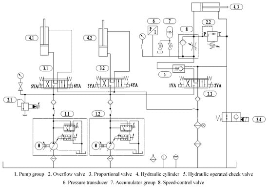
Figure 12.
Hydraulic schematic diagram of HTFDSD.
During forging, when the press descends and the anvil contacts HTFDSD, the load on the vertical cylinder piston rod increases, causing passive retraction. Oil is supplied from the tank through the directional valve to the rodless chamber. Due to the presence of the 5 hydraulic check valve, oil flows into the accumulator, increasing its pressure. Pressure sensor 6 detects this rise and outputs an electrical signal, which opens the proportional valves of the two horizontal cylinder circuits. Displacement feedback is then used to control the extension of the horizontal cylinder piston rods, simulating the axial elongation of the workpiece.
After the anvil rises, the load on the vertical cylinder piston rod decreases, and high-pressure oil from the accumulator pushes the piston rod outward. As the pressure measured by the sensor drops, proportional directional valves 3.1 and 3.2 of the horizontal circuits stop supplying oil, halting horizontal motion. Following the experiment, adjusting the neutral positions of the three proportional directional valves allows all three hydraulic cylinders to reset. The configuration requirements and models of the key hydraulic components are listed in Table 4.

Table 4.
Configuration requirements of key hydraulic components of HTFDSD.
3.3. Control Performance Analysis of HTFDSD
To ensure that HTFDSD accurately replicates the forging’s deformation displacement and response to control signals, two control strategies were developed: conventional PID and fuzzy PID control. Simulation analyses of the horizontal hydraulic cylinders were conducted using both methods. By comparing the response curves and dynamic characteristics of the two strategies, the optimal control method was identified to ensure simulation accuracy. The simulation model is shown in Figure 13.
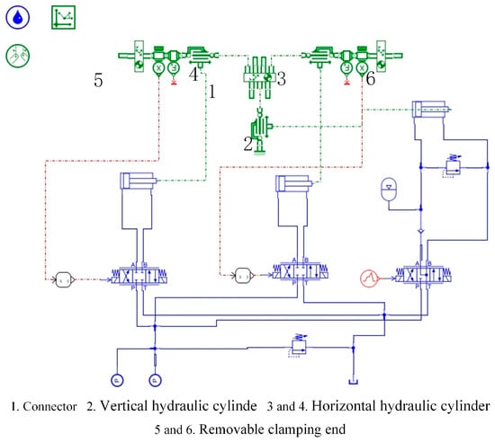
Figure 13.
Simulation model of HTFDSD.
The PID control logic is shown in Figure 14. According to the deformation analysis of the forging, accurate simulation of the elongation process requires the device to meet both displacement and velocity criteria. Therefore, two types of input signals were applied in the simulation: a step signal and a ramp signal. The step signal corresponds to the maximum stroke of the horizontal hydraulic cylinder, set at 120 mm, while the ramp signal represents a typical forging deformation velocity of 10 mm/s with a total displacement of 100 mm. These inputs were used to assess the device’s ability to track displacement and velocity profiles under PID control. During the simulation, the PID parameters were adjusted, and the resulting motion curves are presented in Figure 15.

Figure 14.
PID control logic block diagram.
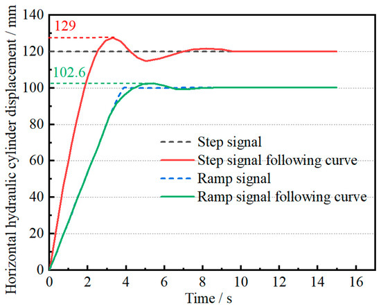
Figure 15.
Motion curve of HTFDSD’s horizontal cylinder under PID control.
As shown in Figure 15, under PID control with a step input signal, the system demonstrates a rise time of approximately 2 s, a peak displacement of 129 mm, a maximum overshoot of 7.5%, and three oscillations, reaching steady state at around 9.4 s. When a ramp signal with a slope of 10 is applied, the system exhibits a maximum overshoot of 2.6% and two oscillations. At this stage, the PID parameters are set to P = 50, I = 10, and D = 5. These results indicate that HTFDSD performs well in tracking low-speed input signals. However, when the piston rod operates at maximum speed, the system experiences larger overshoot and increased oscillations. If the horizontal end of HTFDSD is clamped by a manipulator during operation, such oscillations may significantly affect the accuracy of the experiment. Therefore, the device may not reliably meet simulation requirements under high-speed operating conditions.
Compared to conventional PID control, the fuzzy PID method incorporates a fuzzy controller into the traditional structure. This controller uses the error and its rate of change as inputs, converting them into fuzzy linguistic variables. Based on a set of predefined fuzzy rules, it dynamically adjusts the proportional, integral, and derivative gains of the PID controller. The corrected parameters are then fed back into the PID controller for computation. This approach enables real-time adjustments based on both the magnitude and rate of change in the error, thereby enhancing system stability, responsiveness, and accuracy. The control logic of the fuzzy PID system is shown in Figure 16.

Figure 16.
Fuzzy PID control logic block diagram.
The stroke and velocity ranges of HTFDSD were taken as the input variables, and a 120 mm step signal was applied for simulation. The resulting data were compared with the response curve under conventional PID control. Given the complexity of actual working conditions, deviations may occur in the simulation results. To more accurately assess the operational performance of HTFDSD under real conditions, experimental validation of the horizontal hydraulic cylinder system with fuzzy PID control was conducted. The experimental setup is illustrated in Figure 17.
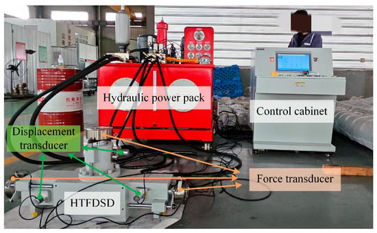
Figure 17.
Schematic diagram of HTFDSD test platform.
The simulation and experimental results are presented in Figure 18. Compared with the conventional PID control method, the system under fuzzy control shows little change in rise time; however, the maximum piston displacement of the hydraulic cylinder decreases from 129 mm to 123 mm, thereby reducing the maximum overshoot from 7.5% to 2.5%. Moreover, the number of oscillations decreases to two, shortening the time to reach steady state from 9.4 s to 6.2 s and enhancing system stability. Under the fuzzy PID control strategy, the experimental curve reaches steady state in 2.46 s, with the steady-state error approaching zero and no significant oscillations observed. These results demonstrate that, under no-load conditions, the system satisfies the operational accuracy requirements and provides an important foundation for subsequent cooperative control experiments of the dual manipulators.
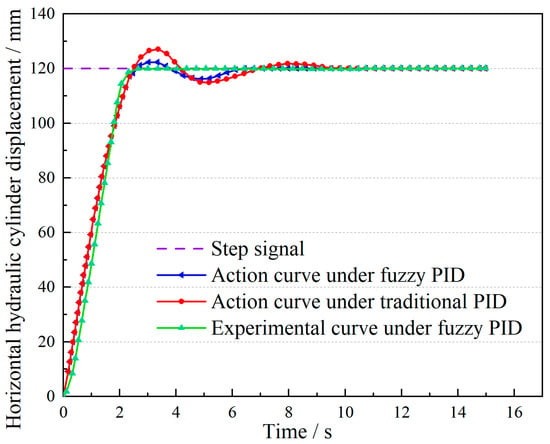
Figure 18.
Comparison curves of traditional PID and fuzzy PID under step signal input.
Under the load constraints applied by the manipulator’s gripper at the end of HTFDSD’s horizontal hydraulic cylinder, minimizing overshoot and oscillations is essential for ensuring the device’s safety and the accuracy of subsequent experiments involving coordination with dual forging manipulators. Therefore, the fuzzy PID control method was selected for displacement control of the horizontal hydraulic cylinder.
4. Co-Simulation Analysis of HTFDSD and Dual Forging Manipulators
Under practical operating conditions, during cooperative control experiments involving HTFDSD and dual manipulators, both ends of the device are constrained by the manipulators’ clamps. These constraints, combined with the coordinated motion of the three systems, lead to continuously varying loads. Such dynamic loads directly affect the device’s dynamic performance, thereby influencing the accuracy of the simulation results. Hence, under dual-manipulator clamping conditions, a systematic analysis of the device’s dynamic performance is required to verify its feasibility in practical applications. The co-simulation model of HTFDSD and the dual forging manipulators is presented in Figure 19.
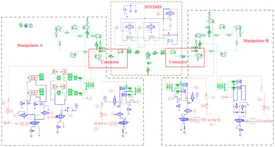
Figure 19.
The co-simulation model of HTFDSD and double forging manipulators.
HTFDSD uses the horizontal elongation deformation curve of the workpiece as its input. The two manipulators provide passive buffering for the cushion cylinders, one through a relief valve and the other through an accumulator. For Manipulator A, the relief valve opening pressure is set to 110 bar based on the hydraulic schematic of the “pilot-scale platform,” whereas Manipulator B employs an accumulator with an initial pressure of 50 bar. In the vertical direction, both HTFDSD and the manipulators’ clamps move downward at a speed of 40 mm/s. A co-simulation of the coordinated motion between HTFDSD and the dual forging manipulators is then carried out, and the results are analyzed separately according to the different buffering methods. The characteristic curve of HTFDSD under different manipulator clamping is shown in Figure 20.
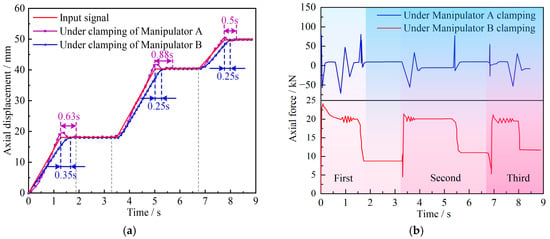
Figure 20.
The characteristic curve of HTFDSD under different manipulator clamping. (a) The displacement curve. (b) The force curve.
Figure 20a presents the displacement curve of HTFDSD under clamping conditions when Manipulator A employs relief valve buffering. The times required to reach steady state in the three stages are 0.63 s, 0.88 s, and 0.5 s, with overshoot values of 3–5%, indicating good overall tracking performance. When Manipulator B adopts accumulator buffering, the displacement curve of HTFDSD reaches steady state in the three stages at 0.35 s, 0.25 s, and 0.25 s, which is significantly shorter than with relief valve buffering, while the overshoot is nearly zero. However, tracking of the input signal shows a certain degree of delay.
To quantitatively assess the tracking accuracy, the coefficient of determination (R2) between the HTFDSD output and the input command signals under different buffering strategies was calculated, as shown in Equation (6). The results indicate that the R2 value for Manipulator A with safety valve buffering is 98.6%, while that for Manipulator B with accumulator buffering is 96.3%. These findings demonstrate that the HTFDSD achieves high-precision deformation simulation across various buffering strategies.
where Ei represents the i-th input signal value, Si denotes the i-th simulated value, and is the mean of all input signal values.
As shown in the force curve in Figure 20b, the relief valve remains closed during the initial stage of motion, producing relatively large force amplitudes on HTFDSD and causing its displacement response to lag slightly behind the input signal. As the piston rod extends, the coupling force between the clamp and HTFDSD increases, and the pressure in the rodless chamber of the cushion cylinder rises to the relief valve’s opening pressure and then stabilizes, enabling the displacement to follow the input signal more accurately. Near the target displacement, variations in piston rod velocity induce pressure fluctuations in the rodless chamber, leading to pronounced force oscillations and, consequently, noticeable overshoot and oscillation in the displacement curve near steady state.
Under accumulator buffering the force applied to HTFDSD is more concentrated and exhibits no large abrupt changes, resulting in a smoother displacement response without severe oscillations. Compared with relief valve buffering, the accumulator continues to exert relatively high forces on HTFDSD even after steady state is achieved, keeping it under a heavier load and thereby causing some delay in the motion of the horizontal cylinder.
In summary, HTFDSD exhibits distinct dynamic characteristics under different manipulator buffering methods. With relief valve buffering by Manipulator A, the device demonstrates good tracking performance; however, sharp pressure variations in the cushion cylinder before and after valve opening cause the displacement curve to show significant overshoot and oscillation during the steady-state phase. With accumulator buffering by Manipulator B, the dynamic response is smoother with minimal overshoot, but the continuous high back pressure provided by the accumulator imposes a heavier load on the device, resulting in a delay in displacement response.
The findings indicate that the dynamic characteristics of HTFDSD are strongly affected by buffering load properties: greater load fluctuations lead to more pronounced displacement oscillations, while higher loads cause more evident tracking delays. Nevertheless, under both clamping conditions, the displacement errors of the piston rods on both sides of the device approach zero after steady state, and the point-to-point error relative to the input signal remains below 5% throughout the process. These results confirm that, under dual-manipulator cooperative clamping on the “5 MN fast-forging hydraulic press pilot platform,” HTFDSD achieves deformation simulation accuracy exceeding 95%, thereby satisfying operational requirements.
5. Expanded Discussion on Error Sources and Limitations
To provide a more comprehensive assessment of the system’s reliability, potential error sources in both the experimentation and modeling processes were critically analyzed. The dynamic response of the HTFDSD can be influenced by several factors:
- Hydraulic System Non-Idealities: Time delays in servo valve response, nonlinear friction in hydraulic cylinders (especially from seal assemblies), and environmental fluctuations affecting hydraulic oil viscosity (e.g., temperature changes) can introduce hysteresis and force ripples, impacting control accuracy and dynamic tracking performance.
- Signal Noise: Measurement noise from sensors (e.g., force and displacement sensors) can affect the feedback signal quality, potentially leading to oscillations in the control system.
- Simulation Simplifications: In the joint simulation model, simplifications were inevitably made. These include mesh deformation in dynamic simulations, which may not perfectly capture localized stress concentrations, and the material modeling of the simulated workpiece, which might not account for all complex high-temperature rheological behaviors. These factors could contribute to discrepancies between simulated and actual physical responses.
While a full quantitative error budget is beyond the current scope, our analysis indicates that hydraulic hysteresis and nonlinear friction are likely the most significant contributors to the observed following lag under large loads. Signal noise primarily exacerbates displacement oscillations during periods of severe load variation. Acknowledging these limitations provides crucial transparency regarding the practical constraints of the HTFDSD. This analysis also offers guidance for future work, suggesting that employing advanced friction compensation techniques, implementing adaptive control strategies to account for oil viscosity changes, and utilizing higher-fidelity material models could significantly mitigate these error sources, thereby enhancing the reproducibility and reliability of the engineering design.
6. Conclusions
To address the challenges of predicting deformation and directly detecting internal forces in high-temperature forgings during dual-manipulator forging processes, a high-temperature forging deformation simulation device was developed based on the “5 MN Fast Forging Hydraulic Press Pilot Platform” at Yanshan University. A joint simulation model was also constructed by integrating the device with the clamping system of dual forging manipulators. Analysis of the dynamic response characteristics of the simulated workpiece under typical cooperative operating conditions verified the feasibility of the device, thereby providing a solid foundation for subsequent research on coordinated control strategies of dual forging manipulators. The main conclusions are as follows:
- Numerical analysis of the deformation behavior of high-temperature forgings during the elongation process was conducted using DEFORM software. The ranges of axial deformation, maximum deformation velocity, and deformation force were determined, establishing the operational specifications and functional requirements of HTFDSD.
- The mechanical structure and hydraulic system of HTFDSD were designed according to engineering requirements. The dynamic response characteristics of the HTFDSD under conventional PID and fuzzy PID control were compared through simulations, and the feasibility of the fuzzy PID control strategy was experimentally validated.
- A joint simulation model combining HTFDSD and the dual forging manipulator clamping system was developed. The dynamic response of the simulated workpiece under typical cooperative operating conditions was analyzed. Results indicate that the dynamic characteristics of HTFDSD are strongly influenced by buffering load: the more severe the load variation, the more pronounced the displacement oscillations; and the larger the load, the more evident the following lag phenomenon.
It is important to note that the experimental results presented herein, which demonstrate the superior performance of fuzzy PID control, are based on representative trials under no-load conditions for the purpose of initial validation. A comprehensive statistical analysis, including repeated experiments under both no-load and various load conditions to compute the mean and standard deviation of key performance indicators, will be conducted as a top priority once the main hydraulic press platform resumes operation. This effort aims to fully quantify the repeatability and operational confidence intervals of the system.
In addition, although the fuzzy PID controller exhibited excellent performance in both simulations and experiments under the tested conditions, a comprehensive quantitative analysis of uncertainties—including sensor measurement errors, system response repeatability, and controller gain sensitivity—is recommended as an essential next step to statistically validate its robustness and establish operational confidence intervals for industrial applications.
7. Patents
Zhai Fugang, Gu Zunzheng. High-temperature forge piece performance simulation device and use method thereof: China, CN202310045390.3[P]. https://worldwide.espacenet.com/patent/search/family/086791357/publication/CN116295608A?q=CN116295608A (accessed on 23 June 2023).
Author Contributions
Conceptualization, F.Z. and Z.G.; methodology, R.Z.; software, Z.G.; validation, X.W., Z.W. and Z.Y.; formal analysis, X.W.; investigation, Z.W.; resources, Z.Y.; data curation, Z.W.; writing—original draft preparation, X.W.; writing—review and editing, F.Z.; visualization, R.Z.; supervision, R.Z.; project administration, F.Z.; funding acquisition, F.Z. All authors have read and agreed to the published version of the manuscript.
Funding
This research was funded by the National Natural Science Foundation of China, grant number 52175064, and the National Science and Technology Major Project, grant number 12124778012.
Institutional Review Board Statement
Not applicable.
Informed Consent Statement
Not applicable.
Data Availability Statement
The original contributions presented in this study are included in the article. Further inquiries can be directed to the corresponding author.
Acknowledgments
The authors would like to thank the journal Materials for supporting the study on related fields over the years, and also thank the reviewers for their valuable opinions on this study.
Conflicts of Interest
Author Zunzheng Gu was employed by the company Forging Division, China National Heavy Machinery Research Institute Co., Ltd. The remaining authors declare that the research was conducted in the absence of any commercial or financial relationships that could be construed as a potential conflict of interest.
Abbreviations
The following abbreviations are used in this manuscript:
| HTFDSD | High-Temperature Forging Deformation Simulation Device |
References
- Ma, H.; Huang, X.; Cui, X.; Wang, P.; Chen, Y.; Hu, Z.; Hua, L. Management Control and Integration Technology of Intelligent Production Line for Multi-Variety and Complex Aerospace Ring Forgings: A Review. Metals 2022, 12, 1079. [Google Scholar] [CrossRef]
- Liu, X.; Qiao, M.; Meng, B. Research on key technology of intelligent production line of aircraft structural parts based on intelligent manufacturing. IOP Conf. Series. Earth Environ. Sci. 2020, 440, 022004. [Google Scholar] [CrossRef]
- Ding, H.; Feng, Z.; Yang, W.; Kecskeméthy, A. Structure synthesis of 6-DOF forging manipulators. Mech. Mach. Theory 2017, 111, 135–151. [Google Scholar] [CrossRef]
- Hou, J.; Zhang, Z.; Zhou, H.; Ning, D.; Gong, Y. Hydraulic systems control based on the characteristics of major-motion mechanism for an open-die forging manipulator. Adv. Mech. Eng. 2017, 9, 81–99. [Google Scholar] [CrossRef]
- Xing, Y.; Zhai, F.; He, Z.; Wang, X.; Zhao, R. Enhanced Force Sensing Method Using BP Neural Network and Sensitive Point Analysis for Forging Manipulator Clamping Mechanism in Operational Conditions. Machines 2025, 13, 226. [Google Scholar] [CrossRef]
- Wang, X.; Zhai, F.; Zhao, R.; Xing, Y.; He, Z. Synchronous control method for the walking system of the dual forging manipulators based on triangular velocity planning. Mech. Based Des. Struct. Mach. 2024, 53, 1228–1248. [Google Scholar] [CrossRef]
- Ding, W.; Deng, H.; Zhang, Y.; Ren, Y. Optimum Design of the Jaw Clamping Mechanism of Forging Manipulators Based on Force Transmissibility. Appl. Mech. Mater. 2012, 157–158, 737–742. [Google Scholar] [CrossRef]
- He, Z.; Zhai, F.; Xing, Y.; Wang, X.; Zhao, R.; Chang, R. Research on the perception capability and characteristics based on the full-attitude indirect sensing model of forging force. Mech. Based Des. Struct. Mach. 2025, 53, 5513–5533. [Google Scholar] [CrossRef]
- Kukuryk, M. Analysis of deformation and microstructural evolution in the hot forging of the Ti-6Al-4V alloy. Arch. Metall. Mater. 2015, 60, 597–604. [Google Scholar] [CrossRef]
- Liu, Y.; Baker, T.N. Deformation characteristics of IMI685 titanium alloy under β isothermal forging solutions. Mater. Sci. Eng. A 1995, 197, 125–131. [Google Scholar] [CrossRef]
- Alimov, A.; Zabelyan, D.; Burlakov, I.; Korotkov, I.; Gladkov, Y. Simulation of deformation behavior and microstructure evolution during hot forging of TC11 titanium alloy. Defect Diffus. Forum. 2018, 385, 449–454. [Google Scholar] [CrossRef]
- Wu, R.H.; Pang, K.C. Computer simulation on formation of precision forgings of titanium alloy and superalloy. Mater. Sci. Forum 2007, 539, 3130–3135. [Google Scholar] [CrossRef]
- Fang, X.; Shao, Y.; Lu, J.; Liu, L. Influence of forging process parameters on residual stress of TC4 titanium alloy forgings. Forg. Stamp. Technol. 2021, 46, 1–8. [Google Scholar] [CrossRef]
- Chen, Y.; Min, X.; Zhang, H.; Dai, J.; Zhou, Y. Effect of strain rate on mechanical properties of tc17 and tc4 alloy forgings. J. Aeronaut. Mater. 2023, 43, 49–59. [Google Scholar] [CrossRef]
- Kim, B.T.; Eom, J.; Choi, I.; Lee, M.C.; Park, S.; Joun, M.S. Computer simulation of complex hot forging processes by a forging simulator based on finite volume method. Trans. Mater. Process. 2007, 16, 187–192. [Google Scholar] [CrossRef][Green Version]
- Zhang, P.; Yao, Z.; Du, Z. Analysis of Forging Compliance Process and Design of the Forging Simulator. J. Shanghai Jiaotong Univ. 2010, 43, 674–677+682. [Google Scholar] [CrossRef]
- Im, C.S.; Suh, S.R.; Lee, M.C.; Kim, J.H.; Joun, M.S. Computer aided process design in cold-former forging using a forging simulator and a commercial cad software. J. Mater. Process. Technol. 1999, 95, 155–163. [Google Scholar] [CrossRef]
Disclaimer/Publisher’s Note: The statements, opinions and data contained in all publications are solely those of the individual author(s) and contributor(s) and not of MDPI and/or the editor(s). MDPI and/or the editor(s) disclaim responsibility for any injury to people or property resulting from any ideas, methods, instructions or products referred to in the content. |
© 2025 by the authors. Licensee MDPI, Basel, Switzerland. This article is an open access article distributed under the terms and conditions of the Creative Commons Attribution (CC BY) license (https://creativecommons.org/licenses/by/4.0/).