Article

Exploring the Impact of Cooling Environments on the Machinability of AM-AlSi10Mg: Optimizing Cooling Techniques and Predictive Modelling

1
State Key Laboratory of Advanced Equipment and Technology for Metal Forming, School of Mechanical Engineering, Shandong University, Jinan 250061, China
2
College of Mechanical and Electrical Engineering, Shandong University of Aeronautics, Binzhou 256600, China
*
Author to whom correspondence should be addressed.
Machines 2025, 13(11), 984; https://doi.org/10.3390/machines13110984 (registering DOI)
Submission received: 18 September 2025 / Revised: 15 October 2025 / Accepted: 21 October 2025 / Published: 24 October 2025
(This article belongs to the Special Issue Neural Networks Applied in Manufacturing and Design)

Abstract

Additively manufactured (AM) aluminum (Al) alloys are very useful in sectors like automotive, manufacturing, and aerospace because they have unique mechanical properties, such as their light weight, etc. AlSi10Mg made by laser powder bed fusion (LPBF) is one of the most promising materials because it has a high strength-to-weight ratio, good thermal resistance, and good corrosion resistance. But machining AlSi10Mg parts is still hard because they have unique microstructural properties from the way they were produced. This research investigates the machining efficacy of the AM-AlSi10Mg alloy in distinct cutting conditions (dry, flood, chilled air, and minimal quantity lubrication with castor oil). The study assesses how different cooling conditions affect important performance metrics such as cutting temperature, surface roughness, and tool wear. Due to castor oil’s superior lubricating and film-forming properties, MQL (Minimal Quantity Lubrication) reduces heat generation between 80 °C and 98 °C for the distinct speed–feed combinations. The Multi-Objective Optimization by Ratio Analysis (MOORA) approach is used to determine the ideal cooling and machining conditions (MQL, Vc of 90 m/min, and fr of 0.05 mm/rev). The relative closeness values derived from the MOORA approach were used to predict machining results using machine learning (ML) models (MLP, GPR, and RF). The MLP showed the strongest relationship between the measured and predicted values, with R values of 0.9995 in training and 0.9993 in testing.

1. Introduction

The aerospace, biomedical, automotive, and defense industries have all adopted additive manufacturing (AM) as a strategic technology due to its rapid developments. The significant benefits of AM for these industries include the potential to cut costs, shorten lead times, reduce component weight due to design freedom, and make components with complicated geometries that are close to net shape [1]. In aerospace applications, AM has demonstrated exceptional versatility across materials and functional domains. For metallic components, techniques such as Selective Laser Melting (SLM) and electron beam melting (EBM) have been adopted to produce high-performance turbine blades and fuel nozzles, which require superior mechanical strength under extreme mechanical loads [2]. Notably, General Electric’s incorporation of AM-fabricated fuel nozzles in their LEAP aircraft engines exemplifies a landmark achievement, reducing the part count from 20 to 1 while achieving a 25% weight reduction and improved durability. Despite these advancements, the integration of AM into aerospace systems faces multifaceted challenges [3].
A powder bed and a 3D CAD file are used in the SLM process to turn metal powders into a finished product, and this method is widely used for the integrated forming of complex aerospace components. The application of titanium alloys, steel, and nickel–chromium alloys commonly used in aerospace manufacturing has been the subject of numerous investigations [4]. Alloys made with aluminum (Al) have also been studied. Al alloys have a promising future due to their low density. When using the SLM method, a platform is constructed using incredibly thin layers of metallic powder, which are subsequently totally melted by the heat energy produced by one or a number of laser beams [5]. By carefully selecting which metallic particles to melt and subsequently re-solidify in each layer, the required 3D object is created. One of the SLM-based techniques is laser powder bed fusion (LPBF). For some applications, especially those that call for decreased porosity, LPBF-developed Al has the potential to replace casting as a production technology [6]. By analyzing the process factors and their effect on porosity, the production of completely dense components from AlSi10Mg generated by LPBF was assessed in several operations. The mechanical and microstructural properties of AM-produced AlSi10Mg were evaluated by Beevers et al. Building orientation, surface polish, heat treatment, platform temperature, and layer thickness (LT) were found to have a significant effect on improving mechanical performance [7]. The surface characteristics and geometric accuracy of the LPBF portion remain inadequate for direct use. Therefore, functional surfaces of LPBF-produced components usually need to be finished by a subtractive process, like any conventional or non-traditional cutting, in order to improve part quality [8]. The manufacturing industry has employed conventional subtractive manufacturing (SM) techniques to improve part quality attributes, which is a somewhat comprehensive solution. Toughness and strength are increased using the LPBF process, which produces a distinctive, anisotropic, and fine-grained microstructure [9]. The machinability of objects made with LPBF may therefore be very different from that of wrought or cast metals, even though they have the same chemical composition. Several physical mechanisms are used in machining to remove material from the work piece (W/p) [10].
When it comes to developing appropriate surfaces for cast or wrought alloys, machining processes are thought to be quite acceptable. Therefore, it is clear that machining is needed to complete the AM components [11]. Using the LPBF technique, Zimmerman et al. investigated the machinability of AM-AlSi10Mg. In relation to the build direction and feed motion during the end milling operation, the surface morphology, process forces, microhardness, and burr development were examined. These were compared to normally cast AlSi10Mg that did not have any coolant applied during machining, in order to clearly analyze the effect. The surface characteristics of AlSi10Mg were shown to be influenced by the production process [12]. Although machining without coolant is environmentally friendly, it significantly reduces machinability by degrading the machined surface and shortening cutter life. Manufacturing divisions typically use cutting fluids (CFs) to handle heat generated during machining. According to the literature, the use of CFs seriously disrupts the atmosphere and endangers human health both during use and disposal [13]. It costs a lot of money to post-treat the CFs for disposal. The machining behavior of anisotropic microstructures of AM parts has not yet been thoroughly examined, despite the fact that numerous research studies on the AM microstructural directionality based on the AM parameters have been carried out [14]. The MQL strategy has gained appeal due to its moderate cost and consideration for human health and the environment. In its broadest definition, the MQL system uses compressed air to spray a very small amount of oil (10–100 mL/h) onto the cutting region [15]. Monsuru et al. [15] examined the effectiveness of a variety of cooling methods (Dry, Flood, and MQL) in solving challenges with temperature, tool wear, and surface morphology when machining AM-AlSi10Mg. The MQL improved the flank wear by 29–45% and 18–31%, respectively, and surface defects were improved by 45–63% and 23–43% when compared to dry and flood conditions [16].
Manufacturing competitiveness has led to an emphasis on enhancing product quality through flexible production facilities and automation. Fully automated machining requires techniques and equipment to forecast and monitor the operation. These will integrate quality assurance and production to fulfill the Six Sigma process control standards [17]. Researchers have found artificial intelligence (AI) to be a strong and effective technique for developing relationships with inadequate data. Through learning and generalization, this AI technique is highly capable of producing significant solutions from a collection of inputs. A sub-division of AI is ML. The ML is the process by which predictive models adjust their parameters in response to system input to increase the accuracy of the estimation. ML is turning out to be a crucial tool for precise modeling of dynamic systems. Prediction of carbon emission [13], tool wear [18], surface quality [19] etc., are some of the recent works performed with the help of ML techniques. Laghari et al. [20] studied the effectiveness of genetic programming (GP) for distinct output responses in the cutting of HMMC. The GP results prove its higher efficiency regarding the prediction of cutting force, surface roughness, and tool life in comparison with RSM. Al Ansari et al. [21] deal with the prediction of HMMC by ANN. According to the inputs, the ANN model had been developed to forecast the surface unevenness. It had been found that ANN showed outstanding prediction with an overall accuracy of 99.48%.
From the literature discussed, (1) it is evident that there is a demand for cutting fluid (C/L) when performing subtractive manufacturing, and (2) it is apparent that the cutting process of AM-AlSi10Mg does not compare with any other ML techniques. Therefore, in this research work, AM-AlSi10Mg was machined with MQL (oil used is castor oil (Cao)) and compared in terms of dry, flood, and air-cooling conditions. Additionally, a MOORA approach was introduced to find the optimal solution. Furthermore, the relative closeness values received from MOORA were employed to perform predictions alongside ML models, and this is a data-driven strategy to improve the quality and performance of machining.

2. Materials and Methods

The L-PBF method was used to produce the AlSi10Mg samples with a 400 W Yb-fiber laser. The AlSi10Mg powder with a particle size range of 20–63 µm and a spherical shape was used. To keep oxidation to a minimum during the melting process, the build chamber was kept in an argon atmosphere. The process parameters based on the best values were chosen based on the literature to make sure that the melt pool stayed stable and had a high density. A layer thickness of 30 µm, a hatch spacing of 0.1 mm, a laser power of 300 W, and a scan speed of 1400 mm/s were used [22,23].
After the fabrication of AlSi10Mg, milling operations were carried out to evaluate its machinability characteristics. Milling was performed on a Feeler FV 1000 vertical machining center; this is a robust CNC machine known for its precision and efficiency in material removal processes. The cutting tool used was a BAP 300R tool holder, fitted with APMT 1135 carbide inserts, which are widely recognized for their excellent cutting performance, wear resistance, and durability when machining composites and alloys. The process parameters, including Vc, fr, and depth of cut (DOC), were selected based on extensive reviews of the literature to ensure optimal cutting conditions and minimize tool wear while achieving a good surface finish. Figure 1 presents the work flow of the investigation. Table 1 presents the details related to the process parameters.

2.1. Cooling Conditions

Four distinct environmental conditions were employed to study the machinability of the fabricated AlSi10Mg to evaluate its performance. No external coolant or lubrication setup was employed for dry cutting. Although dry machining is environmentally friendly, it leads to increased cutting temperature and wear. A ratio of one part oil to twenty parts water was utilized to prepare the flood coolant. Continuous supply of an emulsion-based coolant was used in the cutting area to dissipate heat and lower friction. To evaluate the performance of the machinability, air (chilled air) was used as a coolant. A vortex tube was used to provide chilled air for cooling, and cold air was produced from compressed air without the need for external power. Cao was used as the lubricant for MQL, and an MQL setup was utilized to spray the oil in small droplets close to the cutting area. Cao lowers cutting temperatures, improves surface smoothness, and lessens the friction at the tool-W/p contact due to its greater lubricating qualities and biodegradability. Throughout the MQL operation, a pressure of 4 bar was maintained.

2.2. Measurement

An HTC Model IR Gun, a non-contact IR thermometer, was used to note the cutting heat at the tool-W/p contact area, which is a vital element impacting thermal stress and tool wear. Ra that determines the quality of the machined surface was measured using the SJ-411 roughness tester (Mitutoyo, Aurora, IL, USA), capable of providing reliable values for Ra. Before testing, slip gauges were used to check the error of the instrument. The 3D surface topography was produced with help of Mountain map software (Version 10). Vb is a key indicator of tool life and efficiency, which was assessed by employing an OPTIV optical microscope. JEOL scanning electron microscope (SEM) was utilized for tool wear images.

3. Material Removal and Tool Wear Mechanisms

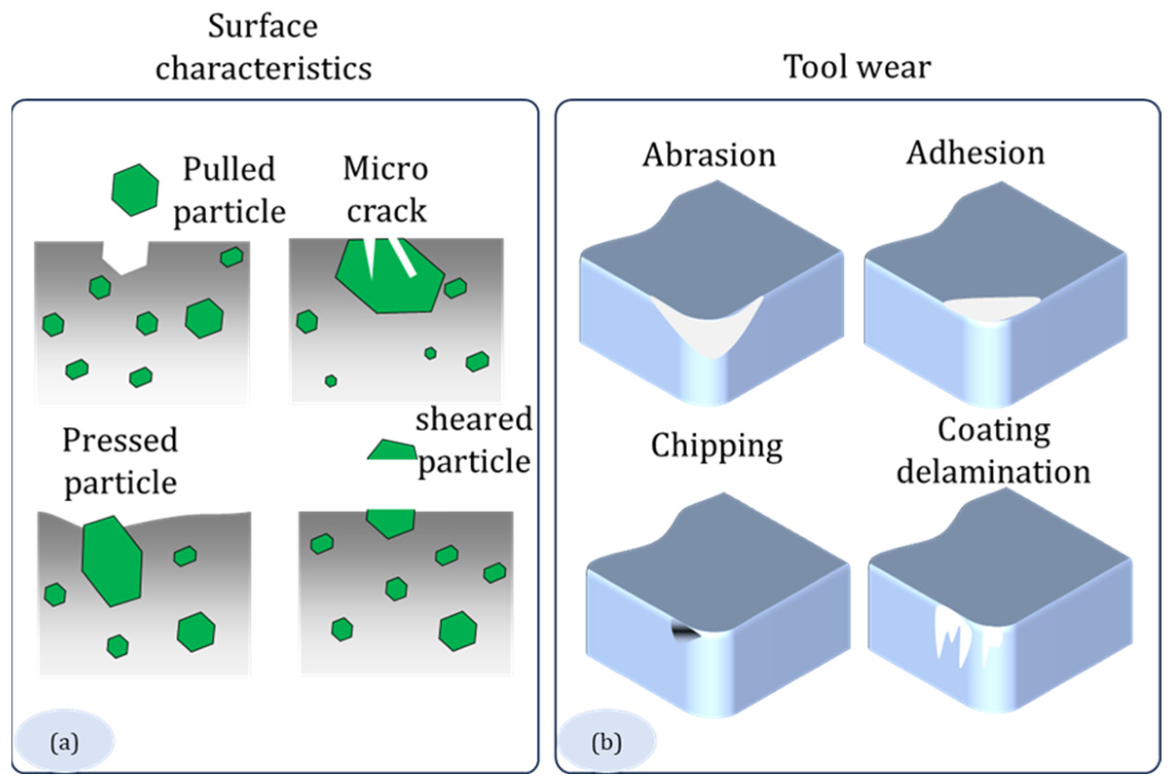
The material removal mechanism of the AlSi10Mg during milling with a PVD-TiAlN coated insert is presented in Figure 2a. There were noticeable characteristics on the machined surface, including (1) pulled, (2) microcrack, (3) pressed, and (4) sheared particles. When the matrix and reinforcement undergo weak bonding, it causes material to separate under distinct speed–feed combinations, which results in pulled particles. The formation of microcracks occurs during the machining process because of localized stress concentrations and thermal loading. The cutting tool pressure causes reinforcing particles to become embedded in the matrix, which results in the formation of pressed particles. On the other hand, sheared particles are the result of severe shear pressures at the junction between the tool and the work material.
Figure 2b presents the common tool wear mechanisms when machining. Material is removed from the cutting edge due to abrasion, which happens when the hard reinforcing particles (Si) in the alloy engage strongly with the tool surface. The tool surface as adhesion forms a built-up edge (BUE) which can worsen tool wear through material transfer from uneven loading. When machining complex intermetallic structures, because of high-impact pressure, chipping will take place. Especially when it comes in contact with hard particles. The heat and mechanical stresses produced during cutting cause coating delamination that slowly weakens the TiAlN coating from the substrate and quickens wear on the tool material. These mechanisms jointly lead to tool damage and hinder machining efficiency and life of the tool.

4. Results and Discussions

4.1. Effect of Temperature

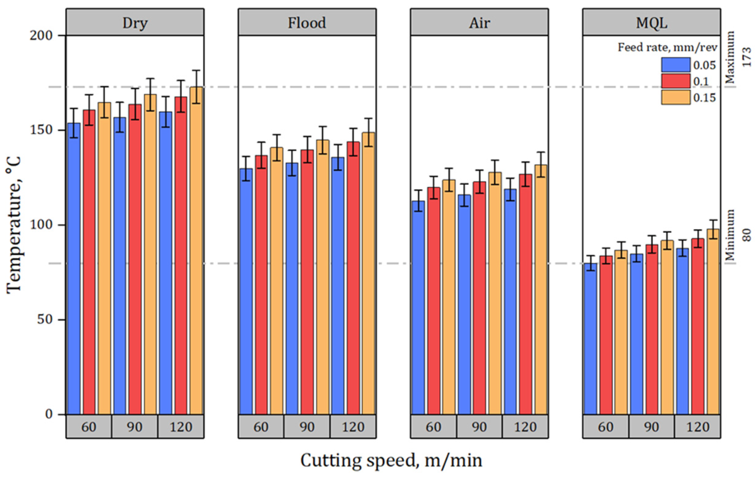
The study examines the effects of various cutting environments on temperature during machining by varying Vc, fr, and coolant type. The environments tested include dry cutting, flood cooling, air, and MQL. Figure 3 presents the effect of cutting temperature under distinct speed–feed combinations and environments. The results demonstrate that dry cutting, as expected, leads to significantly higher temperatures due to the absence of any cooling or lubrication, with temperatures reaching as high as 173 °C at 120 m/min and a fr of 0.15 mm/rev. Such high temperatures can accelerate tool wear, degrade the surface finish, and potentially lead to thermal damage in the material being machined. Flood cooling, which uses a water-based coolant, showed a moderate reduction in temperature (ranging from 130 °C to 149 °C), but still resulted in relatively high heat generation, especially at increased Vcs and frs. Air, an eco-friendly environment, provided a more significant reduction in cutting temperatures, with values ranging from 113 °C to 132 °C. This reduction can be ascribed to the cooling properties of the air, which reduces heat generation at the tool-W/p junction, thus lowering the amount of heat generated during machining. However, the most substantial improvement was observed when MQL with Cao was employed. The combination of air + oil yielded the lowest temperatures across all tested conditions, with values ranging from 80 °C to 98 °C. This decrease in temperature highlights the superior C/L capability of the air + oil mixture. As a vegetable oil, Cao provides superior lubricating and film-forming properties which contribute to lower friction and heat generation between the tool and the W/p [24]. This effect makes it easier for the CF to penetrate deeper into the cutting area between the tool and the W/p, which lubricates better and lowers heat production more effectively.

4.2. Effect of Surface Roughness

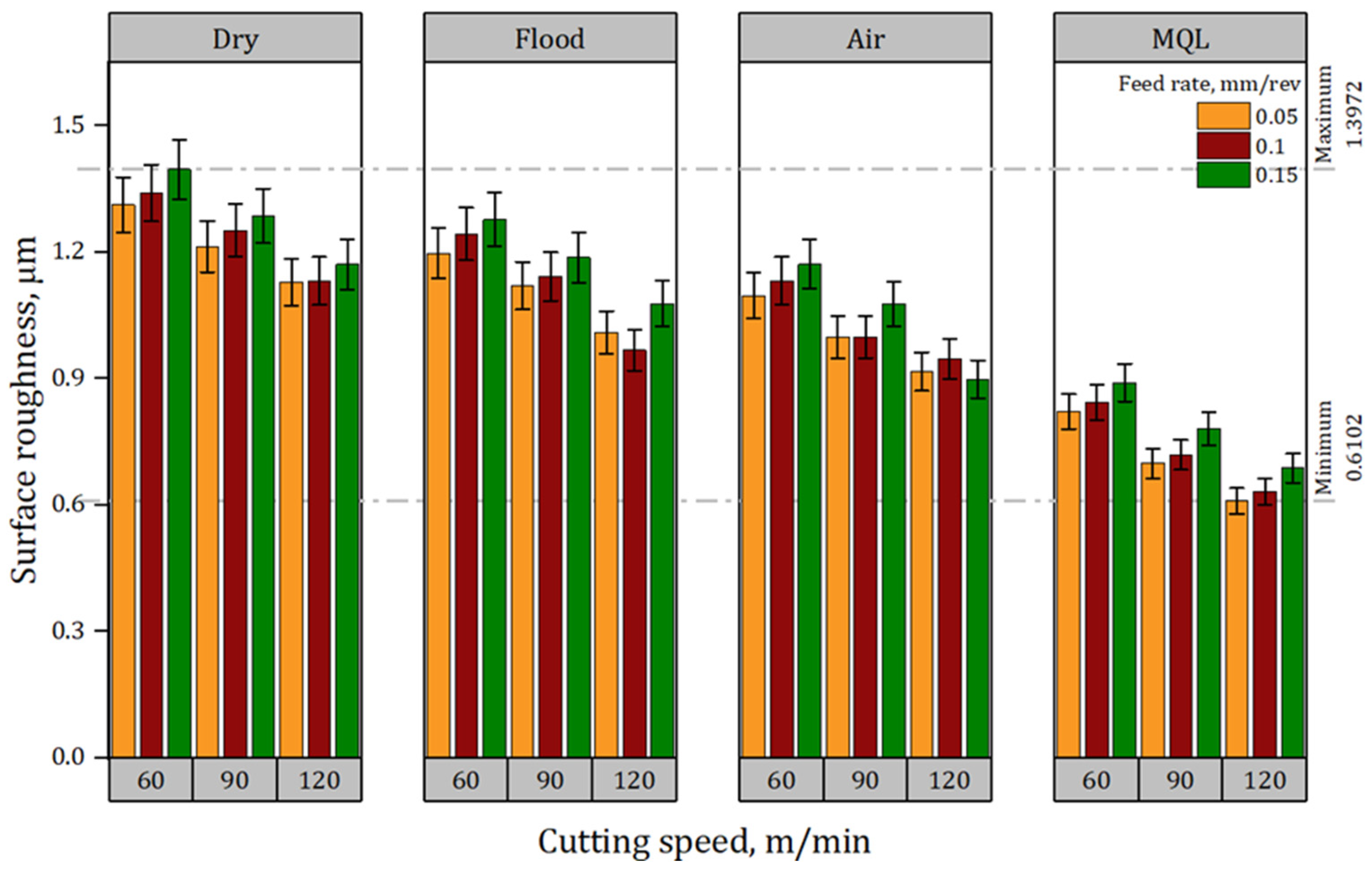
Ra has a direct impact on the part’s durability and performance, making it a crucial indicator of a machined surface’s quality [25]. Figure 4 presents the effect of Ra under distinct speed–feed combinations and environments. Dry cutting produces the highest Ra values. Ra rises with increasing frs because there is no cooling or lubrication, which causes increased vibration and significant tool-W/p friction. At 60 m/min and 0.15 mm/rev, the Ra reaches 1.3972 µm, which is the roughest surface observed under dry conditions. Similarly, even at lower frs, the dry cutting does not offer substantial improvements, with values consistently above 1.1 µm across all Vc. In contrast, the use of flood cooling significantly improves surface finish, with Ra values decreasing as the Vc increases. At 120 m/min and 0.05 mm/rev, the Ra is reduced to 1.01 µm, and at a fr of 0.1 mm/rev, it further drops to 0.9688 µm. This improvement can be ascribed to the cooling effect of the CF, which lowers cutting heat and lessens the surface unevenness. However, while flood cooling performs better than dry cutting, the results indicate that its effect on surface finish is still limited at higher frs. The application of chilled air shows a further reduction in Ra, demonstrating its heat reduction property. At 120 m/min and 0.15 mm/rev, the Ra drops to 0.8991 µm, a notable improvement over both dry and flood environments. The combination of air + oil proves to be the most effective solution for achieving the lowest Ra values across all cutting conditions employed in this investigation. At 120 m/min and 0.15 mm/rev, the Ra is significantly reduced to 0.6881 µm, and at lower frs, the Ra values drop even further, with a minimum of 0.6102 µm recorded at 120 m/min and 0.05 mm/rev. The combination of air and oil not only offers excellent lubrication but also creates a stable barrier among the tool and W/p, reducing tool wear and thereby improving the surface finish [26]. The low Ra values under MQL suggest that this mixture is highly effective at controlling machining forces, vibration, and tool wear, making it ideal for applications that require high-precision surface quality.
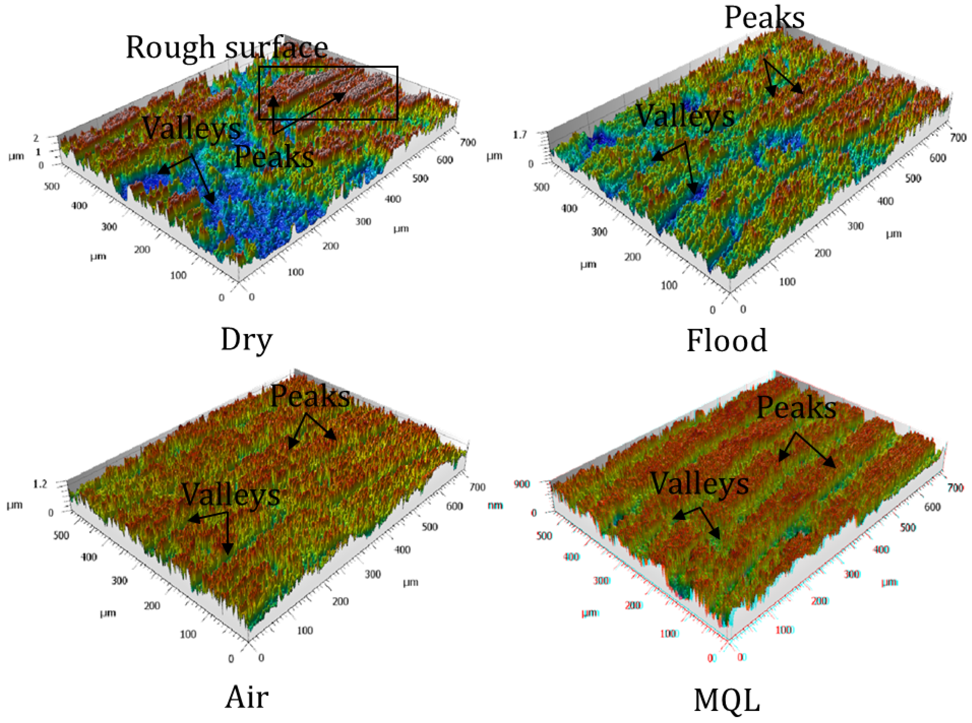
The surface attributes of the machined AM-AlSi10Mg under various cooling conditions were examined in this study using 3D surface plots (Figure 5). A comparative evaluation of the machined surface’s uniformity, waviness, and roughness across different cooling techniques is made possible by these surface plots, which offer an illustrative representation of the surface topography. MQL had the most consistent surface finish and the least number of peaks and valleys of all the cooling conditions. Cao’s efficient C/L properties lower the friction and heat generation at the tool-W/p contact region. MQL creates a protective layer that minimizes tool wear and reduces imperfections on the machined surface, as addressed before in this investigation. On the other hand, greater tool wear and excess heat generation caused higher peaks and valleys under dry and flood conditions. Surface quality was enhanced by air cooling in contrast to dry machining. The capacity of MQL to improve surface integrity was confirmed by the 3D surface plots, which showed a more uniform surface with lesser peaks and valleys.

4.3. Effect of Flank Wear

Vb under various cutting environments highlights the significant impact of L/C on tool degradation during machining [27]. Figure 6 presents the effect of Vb under distinct speed–feed combinations and environments. Under dry cutting conditions, Vb values are the highest. This is a direct consequence of increased friction, heat buildup, and eventual material wear at the contact area among the tool and the W/p [28]. At 120 m/min and 0.15 mm/rev, the wear reaches a peak of 0.188 mm. This rapid wear is detrimental to tool life and results in frequent tool changes, which increase machining downtime and cost. The use of flood coolants provide a moderate improvement in reducing tool wear. Flood cooling’s primary function is to reduce the temperature at the tool-W/p junction, thereby slowing down the rate of tool wear. However, its effectiveness is limited, particularly at higher frs, as it primarily controls temperature but does not provide substantial lubrication. At 120 m/min and 0.15 mm/rev, the Vb is still relatively high at 0.16 mm. Even though the tool experiences less thermal damage compared to dry cutting, mechanical wear due to friction remains a challenge. Air cooling significantly reduces Vb by creating a cushion between the tool and W/p. The wear decreases to 0.127 mm at 120 m/min and 0.15 mm/rev, which is a noticeable improvement compared to both dry and flood conditions. MQL controls temperature and minimizes tool-W/p contact friction, resulting in a slower wear process. The lowest Vb across all conditions is achieved by the combination of air + oil, which further improves the protective effect. Cao, renowned for its high viscosity and film-forming capabilities, improves the lubricating capability at the cutting junction [24]. Wear is decreased to 0.093 mm at the same speed–feed combination (120 m/min and 0.15 mm/rev). MQL has the potential to greatly increase tool life by lowering Vb, enabling longer continuous machining cycles, and lowering the frequency of tool replacements. By reducing wear, this lubricant mixture improves machining performance and controls surface quality and dimensional accuracy throughout longer production cycles. This reduces lubricant consumption and waste compared to synthetic- or petroleum-based coolants, improving tool efficiency and sustainable machining.
Figure 7 presents the SEM images of the flank side at a Vc of 120 m/min and a fr of 0.15 mm/rev. The combined impacts of high friction, heat stresses, and mechanical wear processes resulted in adhesion, abrasion, coating peel-off, and chipping in both dry and flood conditions. Because there is no lubrication or cooling during dry machining, the cutting area temperature rises significantly, increasing tool-W/p contact and promoting a strong adhesive connection between the W/p material and the tool surface. Material is transferred onto the tool because of this adhesion, eventually creating a BUE that eventually separates and leads to uneven tool wear. Moreover, excessive heat buildup weakens the coating and causes it to peel off; mechanical and thermal stresses produce localized material fracture that chips the cutting edge [29]. Introducing a constant coolant flow during flood machining helps to control the cutting area’s heat, minimizing tool thermal softening and minimizing adhesion and abrasive wear to some extent when compared to dry cutting. The tool material’s cyclic expansion and contraction is a contributing factor to coating peel-off. When the coolant suddenly cools down an overheated area, thermal cracking might result and cause a brittle cutting edge fracture, which is the reason for chipping. There was adhesion, abrasion, and peel-off of the coating under air and MQL conditions but no chipping. Even though convective heat loss happens to some extent during air cooling, it is not enough to significantly decrease the cutting temperature. On the other hand, MQL lessens direct metal-to-metal contact by supplying a fine mist of lubricating oil. In addition to reducing excessive heat accumulation, the thin lubricating film that forms between the tool and W/p lessens the severity of tool wear compared to other cutting conditions. Material transfer has taken place throughout the machining process, as evidenced by the presence of Fe as a parent element from AlSi10Mg under all cutting techniques. The main forces for material transfer are adhesion and diffusion wear processes. High friction and high cutting temperatures during dry and flood conditions promote diffusion between the W/p and tool, which results in material transfer. Even while lubrication lessens direct metal-to-metal contact under MQL conditions, the presence of Fe still verifies that some amount of diffusion has occurred.

5. Optimizations with MOORA

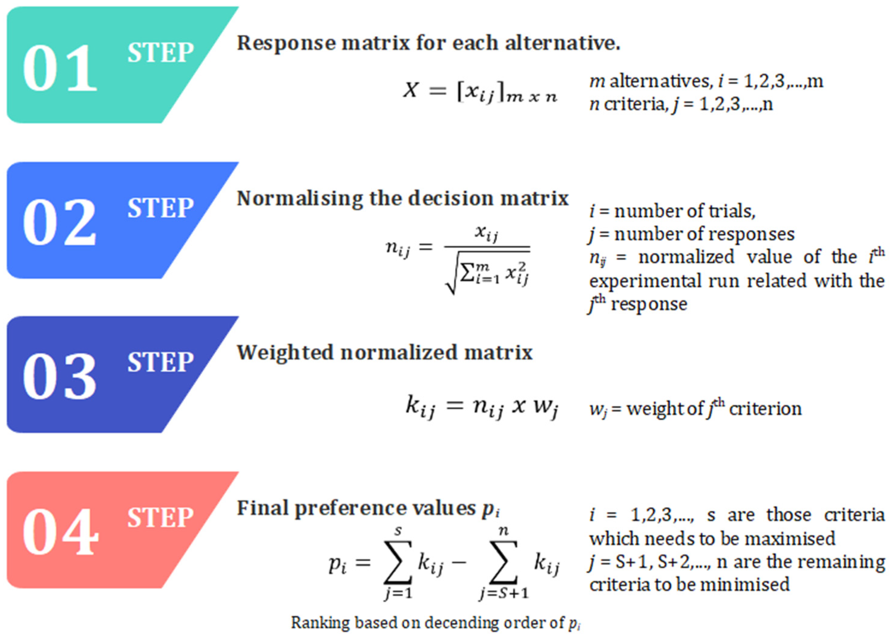
The MOORA (Multi-Objective Optimization on the basis of Ratio Analysis) method is a mathematical tool that helps in ranking the options where multiple outcomes are involved. This method considers both maximization and minimization objectives while computing the single preference value. This method has wide applications where performance evaluation, material selection, quality control, etc., are involved. Figure 8 presents the steps involved in the MOORA method.
The MOORA-based detailed analysis is presented in Table 2. From the MOORA method, a design combination of cutting fluid (air with oil, with a Vc of 90 m/min and a fr of 0.05 mm/rev) resulted in the highest relative closeness, and hence this design combination attained first place when compared with other alternatives. And for this optimal combination, a cutting temperature of 85 °C was observed, which seems to be in an optimal range, thus ensuring the prevention of overheating in the tool and the W/p. The Ra for this combination was observed to be 0.6999 µm, thus indicating a fine surface finish, enabling it to meet the demand of high-precision applications with good surface quality. Furthermore, being a key indicator of tool degradation, Vb for this optimal combination was observed as 0.078 mm. Lower Vb ensures the prolonged use of the tool without replacement and thus results in reduced operational costs.

6. Machine Learning

Incorporating machine learning (ML) into machining processes has become a game-changing approach due to the complicated and continuous interdependence between process factors and performance outcomes [30]. To minimize manufacturing costs, and increase product quality and working efficiency, this research uses ML techniques to provide accurate predictions that can accurately forecast tool life and surface roughness. Surface roughness directly affects machined part quality, whereas tool life affects resource utilization and production downtime [31]. ML-driven techniques encourage active decision-making and lower the dependency on expensive experiments. Figure 9 shows the process flow of ML in the machining process (https://www.vecteezy.com/). The ML models employed in this research work are explained below.
  • Gaussian Process Regression
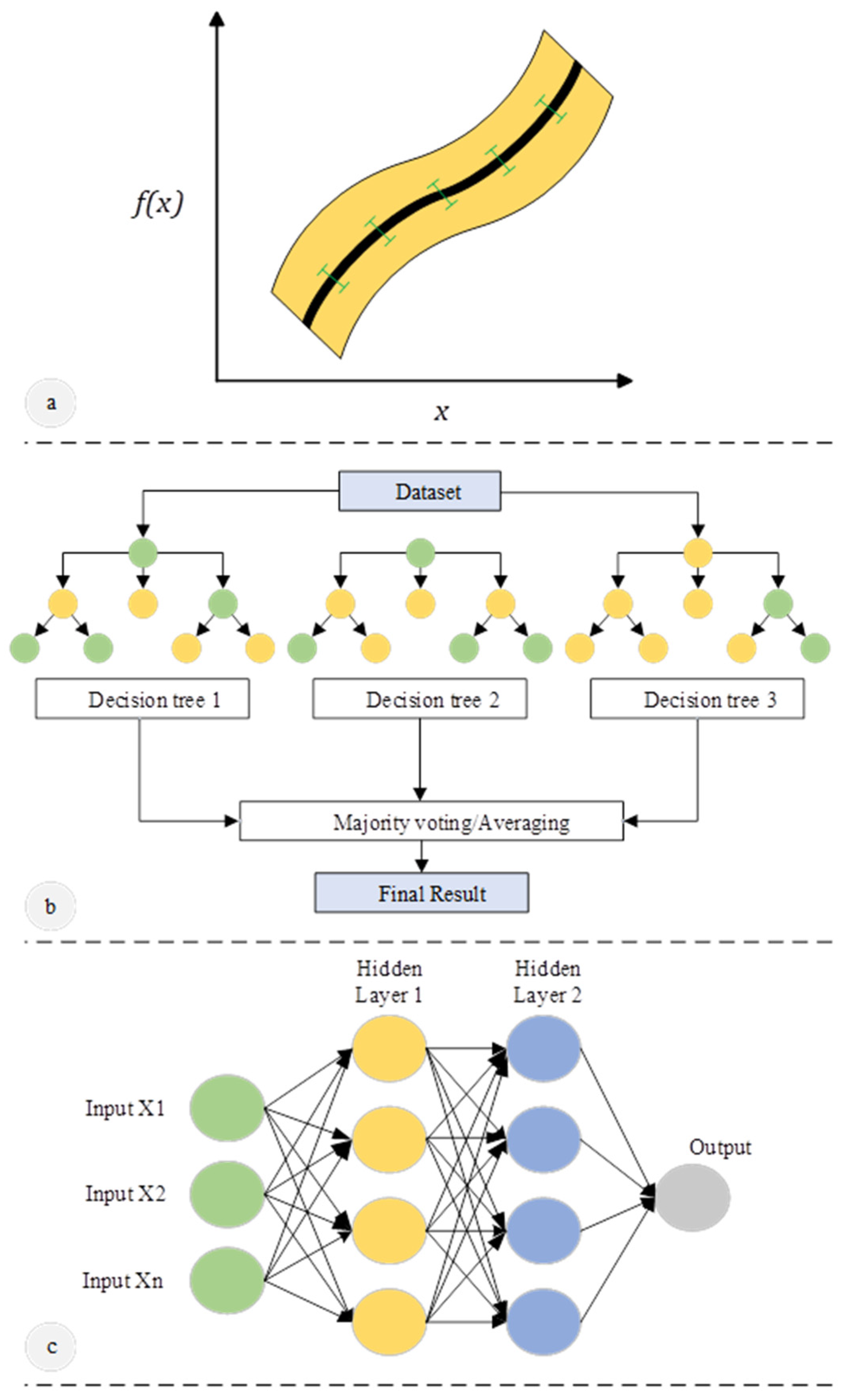
GPR is a well-established ML model [32]. As observations are made, it holds a posterior distribution and is predicated on the fact that the unknown forecast function is sampled from a multivariate Gaussian distribution. Figure 10a presents the schematic of GPR. According to the estimate of the covariance matrix, whose elements indicate the covariance between two features, the variance and mean for objective values can be accurately predicted. The main benefit of GPR is its ability to provide prediction uncertainty, which is a crucial component of active learning for the design of materials.
  • Random Forest
Algorithms that are based on decision trees, such as RF, are highly effective non-linear ML techniques [33]. Figure 10b presents the schematic of RF. The RF technique is an ensemble model that works to improve the performance of the model by combining numerous decision trees, each of which is trained using a randomized process. A weighted average or vote is then used to determine the outcome of each prediction, regardless of whether it is for regression or classification. The inherent evaluation of feature relevance provided by Random Forest helps find influential descriptors.
  • Multi-Layer Perceptron
One kind of neural network utilized for tasks like regression and classification is MLP [34]. Figure 10c presents the schematic of MLP. The architecture includes an input layer, an output layer, and one or more hidden layers. Each input neuron in the network is supplied by some weights, which are then added up, and the result is passed through an activation function like a sigmoid or rectified linear unit (ReLU) to learn complex patterns. Backpropagation technique is used to train the network and modifies the weights to reduce the variations among predicted and actual outcomes. MLP is widely used because MLP can efficiently handle relationships that are not linear.

6.1. Prediction

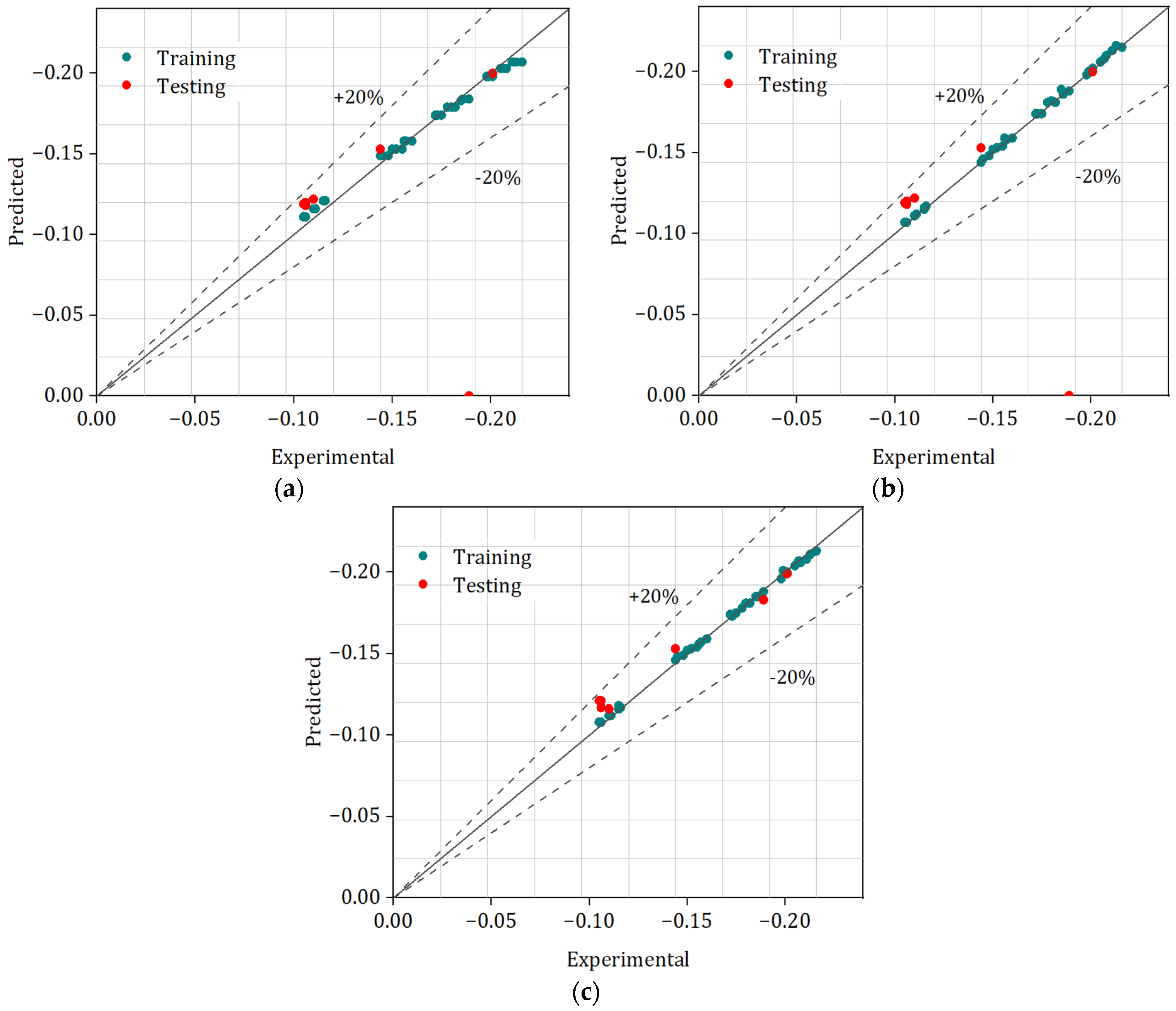
ML techniques GPR, MLP, and RF were used to assess predictive accuracy. The degree and direction of association among the predicted and measured values are assessed by the correlation coefficient (R). Figure 11a–c presents the training and testing of different algorithms (GPR, MLP, and RF). In this work, the Pi values were employed as the input for the prediction with different algorithms. A prediction model that is more accurate is indicated by a number that is near to 1. MLP exhibited the most predictive power and the best agreement between predicted and measured values, with training and testing R values of 0.9995 and 0.9993, respectively. GPR’s marginally lower R values of 0.9987 in training and 0.9963 in testing showed that MLP was the most accurate in detecting data connections, while RF came in second with R values of 0.9995 in training and 0.9944 in testing. A greater performance was achieved by the MLP, with two hidden layers present throughout both training and testing. Layered neural networks can describe complex non-linear data interactions, making the MLP strong. Two hidden layers allow the MLP to capture complex patterns, making it perfect for applications that require deep input feature knowledge. RF comes next to MLP in terms of predictive accuracy. This technique reduces overfitting and helps RF to control data variability by averaging results. Overall, RF performed well, though its prediction accuracy was marginally lower than that of MLP. In this study, GPR is ranked last in terms of its ability to evaluate prediction. Certain data sets respond well to GPR; however, it is unable to identify complex trends like MLP and RF.

6.2. Evaluation Metrics

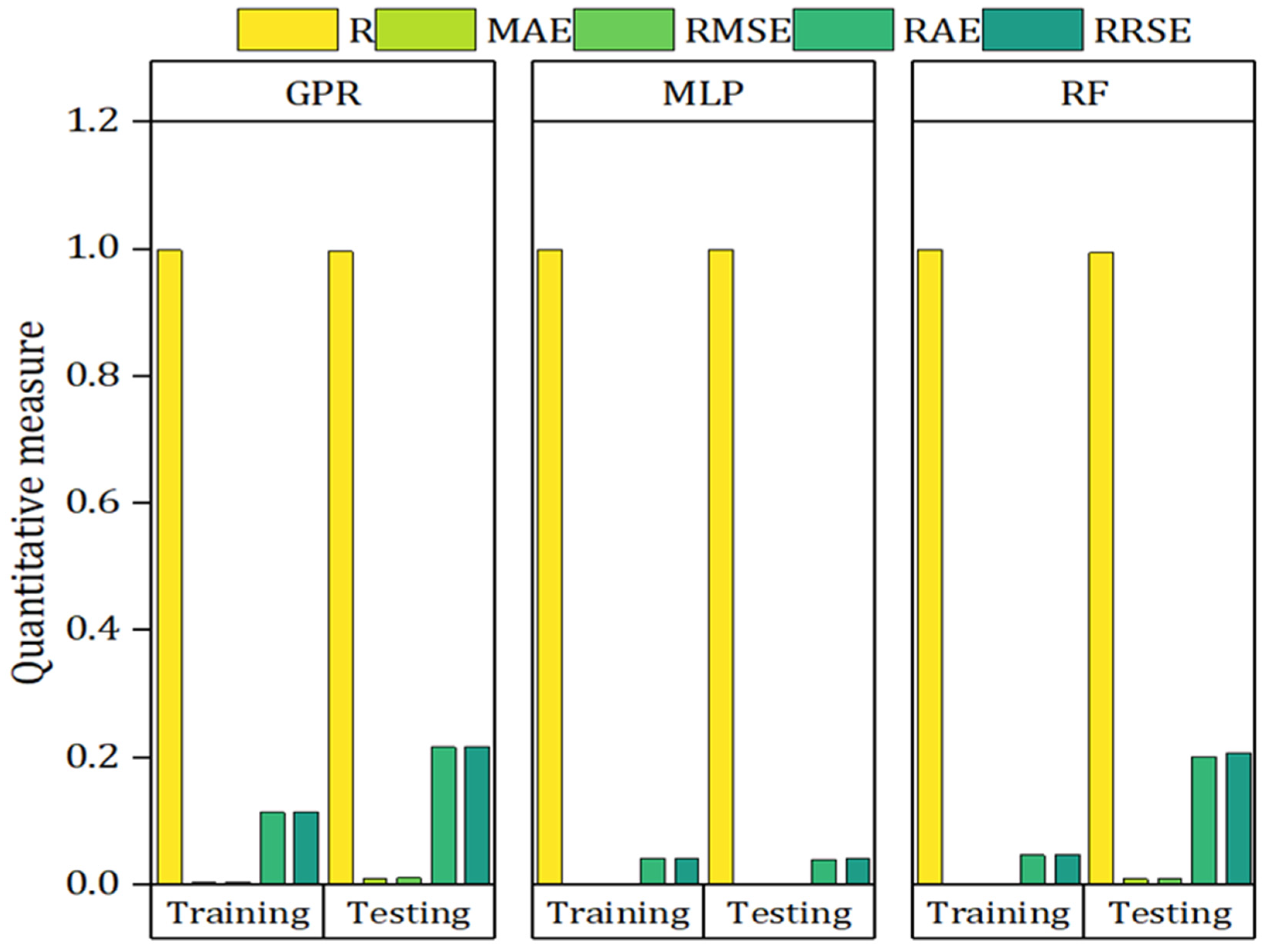
Mean Absolute Error (MAE), Root Mean Squared Error (RMSE), Relative Absolute Error (RAE), and Root Relative Squared Error (RRSE) were employed to assess the performance of the three ML models—GPR, MLP, and RF—for both the training and testing stages. Figure 12 presents the quantitative analysis of different metrics. With an MAE of 0.0013 in training and 0.0018 in testing, MLP demonstrated greater precision and the lowest error rates in terms of MAE. GPR exhibited more errors with 0.0035 in training and 0.01 in testing, while RF recorded training MAEs of 0.0014 and 0.0093 (testing MAE), demonstrating MLP’s superior accuracy. With 0.0015 in training and 0.0021 in testing, MLP maintained the lowest RMSE values. RF came in second with 0.0017 in training and 0.0103 in testing, and GPR came in third with 0.0041 in training and 0.0108 in testing. The RAE values further showed MLP’s better performance, exhibiting the lowest RAE values of 4.14% in training and 3.91% in testing, whereas RF recorded 4.66% in training and 20.14% in testing. GPR demonstrated the greatest RAE values, showing 11.36% in training and 21.64% in testing. With training and testing values of 4.21% and 4.17%, respectively, MLP showed the lowest RRSE values. The highest RRSE value was obtained by GPR, with 11.45% in training and 21.73% in testing, while RF recorded 4.75% in training and 20.79% in testing. MLP was the most accurate algorithm for high-accuracy predictions in this data set, followed by RF with its reliable but slightly less exact predictions, and GPR, which was the least accurate due to its limits.

7. Conclusions

In this research work, AM-AlSi10Mg was machined with distinct cooling conditions (MQL, dry, flood and air). In addition, the MOORA approach was introduced to find the optimal solution, and the final MOORA scores were employed to examine prediction using ML models. The resulting inferences were as follows:
  • The machining environment has a major impact on the cutting temperature; dry cutting yields the highest temperature, 173 °C, at 120 m/min and 0.15 mm/rev. The greatest shift is made with MQL employing Cao, which reduces heat generation (80–98 °C) because of its excellent lubricating and film-forming qualities.
  • Due to higher friction and vibration, dry cutting produces the highest Ra values at 60 m/min and 0.15 mm/rev, and the peak Ra is 1.3972 µm. By minimizing friction and tool wear, MQL produces the best results, lowering Ra to 0.6102 µm at 120 m/min and 0.05 mm/rev. With the lowest Ra values across all the conditions, the air and oil combination turns out to be the most efficient.
  • MQL effectively lowers Vb, making it the most successful C/L method. It prolongs tool life, reduces friction, and stops excessive heat buildup with its thin oil spray. MQL ensures stable cutting performance by reducing severe adhesion and coating peel-off, in contrast to other conditions. By lowering wear and metal transfer, the enhanced lubrication maintains superior surface quality.
  • The ideal machining parameters, which ensure effective performance, were determined by the MOORA method to be MQL, with a Vc of 90 m/min, and fr of 0.05 mm/rev. This combination reduced tool wear (Vb = 0.078 mm), maintained an ideal temperature of 85 °C, and produced a fine Ra of 0.6999 µm. The outcomes verify enhanced surface quality, longer tool life, and lower operating expenses, making it perfect for precision machining.
  • With R values of 0.9993 in testing and 0.9995 in training, MLP demonstrated the highest correlation between predicted and measured values, surpassing GPR and RF in terms of predictive accuracy. Furthermore, MLP had the lowest error rates in both the training and testing stages and showed higher accuracy across all assessment metrics (MAE, RMSE, RAE, and RRSE).

Author Contributions

Conceptualization, Z.D. and K.G.; methodology, Z.D.; software, J.S.; validation, X.H. and Z.D.; formal analysis, K.G. and J.S.; investigation, Z.D.; resources, X.H.; data curation, X.H.; writing—original draft preparation, Z.D.; writing—review and editing, K.G. and J.S.; visualization, Z.D.; supervision, J.S.; project administration, X.H.; funding acquisition, K.G. All authors have read and agreed to the published version of the manuscript.

Funding

This research was funded by the Civil Aerospace Technology Pre-research Project, grant number D020110, and the Jining Key Research and Development Program, grant number 2022KJHZ013.

Data Availability Statement

The original contributions presented in the study are included in the article; further inquiries can be directed to the corresponding author.

Conflicts of Interest

The authors declare no conflicts of interest. The funders had no role in the design of the study; in the collection, analyses, or interpretation of data; in the writing of the manuscript; or in the decision to publish the results.

Abbreviations

The following abbreviations are used in this manuscript:
AMAdditively Manufactured
LPBFLaser powder bed fusion
EBMElectron Beam Melting
MQLMinimal Quantity Lubrication
MOORAMulti-Objective Optimization by Ratio Analysis
MLMachine Learning
MLPMulti-Layer Perceptron
GPRGaussian Process Regression
RFRandom Forest
SLMSelective Laser Melting
LTLayer thickness
SMSubtractive Manufacturing
GPGenetic Programming
BUEBuilt-up Edge
MAEMean Absolute Error
RMSERoot Mean Squared Error
RAERelative Absolute Error
RRSERelative Squared Error

References

  1. Lee, H.; Lim, C.H.J.; Low, M.J.; Tham, N.; Murukeshan, V.M.; Kim, Y.J. Lasers in additive manufacturing: A review. Int. J. Precis. Eng. Manuf.-Green Technol. 2017, 4, 307–322. [Google Scholar] [CrossRef]
  2. Boretti, A. Metal additive manufacturing for internal combustion enginecomponents: A narrative review of applications, materials, processes, challenges, and future directions. Int. J. Adv. Manuf. Technol. 2025, 139, 6355–6397. [Google Scholar] [CrossRef]
  3. Pardeep, P.D. Exploring the Role of 3D Printing in Aerospace Engineering: Innovations in Lightweight Structural Components. Shodh Prakashan J. Eng. Sci. Res. 2025, 1, 77–98. [Google Scholar]
  4. Obeidi, M.A. Metal additive manufacturing by laser-powder bed fusion: Guidelines for process optimisation. Results Eng. 2022, 15, 100473. [Google Scholar] [CrossRef]
  5. Aboulkhair, N.T.; Simonelli, M.; Parry, L.; Ashcroft, I.; Tuck, C.; Hague, R. 3D printing of Aluminium alloys: Additive Manufacturing of Aluminium alloys using selective laser melting. Prog. Mater. Sci. 2019, 106, 100578. [Google Scholar] [CrossRef]
  6. Taghian, M.; Mosallanejad, M.H.; Lannunziata, E.; Del Greco, G.; Iuliano, L.; Saboori, A. Laser powder bed fusion of metallic components: Latest progress in productivity, quality, and cost perspectives. J. Mater. Res. Technol. 2023, 27, 6484–6500. [Google Scholar] [CrossRef]
  7. Poncelet, O.; Marteleur, M.; van der Rest, C.; Rigo, O.; Adrien, J.; Dancette, S.; Dancette, S.; Simar, A. Critical assessment of the impact of process parameters on vertical roughness and hardness of thin walls of AlSi10Mg processed by laser powder bed fusion. Addit. Manuf. 2021, 38, 101801. [Google Scholar] [CrossRef]
  8. Soe, A.N.; Sombatmai, A.; Promoppatum, P.; Srimaneepong, V.; Trachoo, V.; Pandee, P. Effect of post-processing treatments on surface roughness and mechanical properties of laser powder bed fusion of Ti–6Al–4V. J. Mater. Res. Technol. 2024, 32, 3788–3803. [Google Scholar] [CrossRef]
  9. Ross, N.S.; Srinivasan, N.; Ananth, M.B.J.; AlFaify, A.Y.; Anwar, S.; Gupta, M.K. Performance assessment of different cooling conditions in improving the machining and tribological characteristics of additively manufactured AlSi10Mg alloy. Tribol. Int. 2023, 186, 108631. [Google Scholar] [CrossRef]
  10. Schneider, S.A.; Hermsen, S.; Kirchmann, S.; Ganser, P.; Bergs, T.; Schleifenbaum, J.H. Machinability Analysis for Milling of Additively Manufactured Inconel 718 with Specifically Induced Porosity; Gottfried Wilhelm Leibniz Universität Hannover, Institut für Fertigungstechnik und Werkzeugmaschinen: Hannover, Germany, 2022; pp. 51–58. [Google Scholar]
  11. Bandyopadhyay, A.; Traxel, K.D.; Lang, M.; Juhasz, M.; Eliaz, N.; Bose, S. Alloy design via additive manufacturing: Advantages, challenges, applications and perspectives. Mater. Today 2022, 52, 207–224. [Google Scholar] [CrossRef]
  12. Zimmermann, M.; Müller, D.; Kirsch, B.; Greco, S.; Aurich, J.C. Analysis of the machinability when milling AlSi10Mg additively manufactured via laser-based powder bed fusion. Int. J. Adv. Manuf. Technol. 2021, 112, 989–1005. [Google Scholar] [CrossRef]
  13. Ross, N.S.; Rai, R.; Ananth, M.B.J.; Srinivasan, D.; Ganesh, M.; Gupta, M.K.; Korkmaz, M.E.; Krolczyk, G.M. Carbon emissions and overall sustainability assessment in eco-friendly machining of Monel-400 alloy. Sustain. Mater. Technol. 2023, 37, e00675. [Google Scholar] [CrossRef]
  14. Wood, P.; Díaz-Álvarez, J.; Rusinek, A.; Gunputh, U.; Bahi, S.; Díaz-Álvarez, A.; Miguélez, M.H.; Lu, Y.L.; Platek, P.; Sienkiewicz, J. Microstructure effects on the machinability of AM-produced superalloys. Crystals 2023, 13, 1190. [Google Scholar] [CrossRef]
  15. Lubis, M.I.J.; Ginting, A. A Review: Development of MQL systems applied for metal cutting. In Proceedings of the IOP Conference Series: Materials Science and Engineering, Medan, Indonesia, 3–4 September 2020; IOP Publishing: Bristol, UK, 2020. [Google Scholar]
  16. Ramoni, M.; Shanmugam, R.; Ross, N.S.; Gupta, M.K. An experimental investigation of hybrid manufactured SLM based Al-Si10-Mg alloy under mist cooling conditions. J. Manuf. Process. 2021, 70, 225–235. [Google Scholar] [CrossRef]
  17. Radhika, N.; Babudeva Senapathi, S.; Subramaniam, R.; Subramany, R.; Vishnu, K.N. Pattern recognition based surface roughness prediction in turning hybrid metal matrix composite using random forest algorithm. Ind. Lubr. Tribol. 2013, 65, 311–319. [Google Scholar] [CrossRef]
  18. Babu, T.R.; Samuel, G.L. Prediction of Machining Quality and Tool Wear in Micro-Turning Machine Using Machine Learning Models. In Advances in Micro and Nano Manufacturing and Surface Engineering: Proceedings of AIMTDR 2021; Springer Nature: Singapore, 2022; pp. 1–12. [Google Scholar]
  19. Bustillo, A.; Pimenov, D.Y.; Mia, M.; Kapłonek, W. Machine-learning for automatic prediction of flatness deviation considering the wear of the face mill teeth. J. Intell. Manuf. 2021, 32, 895–912. [Google Scholar] [CrossRef]
  20. Laghari, R.A.; Pourmostaghimi, V.; Laghari, A.A.; Qazani, M.R.C.; Sarhan, A.A. Genetic modeling for enhancing machining performance of high-volume fraction 45% SiCp/Al particle reinforcement metal matrix composite. Arab. J. Sci. Eng. 2025, 50, 9043–9059. [Google Scholar] [CrossRef]
  21. Al Ansari, M.S.; Kaliappan, S.; Mrudula, G.; Dehankar, P.B.; Maranan, R.; Teja, P.V.S. Optimizing Milling Parameters for Al7075/nano SiC/TiC Hybrid Metal Matrix Composites using Taguchi Analysis and ANN Prediction. E3S Web Conf. 2024, 556, 01021. [Google Scholar]
  22. Hong, Y.; Guo, K.; Sun, J.; Yang, B.; Zhang, C. Investigation on vibration properties of 3D printed lattice structures filled with tin–bismuth alloy. J. Appl. Phys. 2022, 131, 065105. [Google Scholar] [CrossRef]
  23. Sun, Q.; Sun, J.; Guo, K.; Liu, J. Investigation on mechanical properties and energy absorption capabilities of AlSi10Mg triply periodic minimal surface sheet structures fabricated via selective laser melting. J. Mater. Eng. Perform. 2022, 31, 9110–9121. [Google Scholar] [CrossRef]
  24. Jia, D.; Li, C.; Zhang, Y.; Yang, M.; Wang, Y.; Guo, S.; Cao, H. Specific energy and surface roughness of minimum quantity lubrication grinding Ni-based alloy with mixed vegetable oil-based nanofluids. Precis. Eng. 2017, 50, 248–262. [Google Scholar] [CrossRef]
  25. Korkmaz, M.E.; Gupta, M.K.; Ross, N.S.; Sivalingam, V. Implementation of green cooling/lubrication strategies in metal cutting industries: A state of the art towards sustainable future and challenges. Sustain. Mater. Technol. 2023, 36, e00641. [Google Scholar] [CrossRef]
  26. Ross, N.S.; Mashinini, P.M.; Mishra, P.; Ananth, M.B.J.; Mustafa, S.M.; Gupta, M.K.; Korkmaz, M.E.; Nag, A. Enhancing surface quality and tool life in SLM-machined components with Dual-MQL approach. J. Mater. Res. Technol. 2024, 31, 1837–1852. [Google Scholar] [CrossRef]
  27. Ramanan, K.V.; Ramesh Babu, S.; Jebaraj, M.; Nimel Sworna Ross, K. Face turning of Incoloy 800 under MQL and nano-MQL environments. Mater. Manuf. Process. 2021, 36, 1769–1780. [Google Scholar] [CrossRef]
  28. Ross, N.S.; Sheeba, P.T.; Shibi, C.S.; Gupta, M.K.; Korkmaz, M.E.; Sharma, V.S. A novel approach of tool condition monitoring in sustainable machining of Ni alloy with transfer learning models. J. Intell. Manuf. 2024, 35, 757–775. [Google Scholar] [CrossRef]
  29. Gupta, M.K.; Mia, M.; Jamil, M.; Singh, R.; Singla, A.K.; Song, Q.; Liu, Z.Q.; Khan, A.M.; Sarikaya, M. Machinability investigations of hardened steel with biodegradable oil-based MQL spray system. Int. J. Adv. Manuf. Technol. 2020, 108, 735–748. [Google Scholar] [CrossRef]
  30. Karabacak, Y.E. Intelligent milling tool wear estimation based on machine learning algorithms. J. Mech. Sci. Technol. 2024, 38, 835–850. [Google Scholar] [CrossRef]
  31. Sivalingam, V.; Zhou, Q.; Ross, N.S.; Tiwari, S.; Selvam, B.; Sun, J.; Gupta, M.K. Identification of tool wear and surface morphology measurements in sustainable milling of Al 6082 hybrid metal matrix composite. J. Mater. Res. Technol. 2023, 27, 7570–7581. [Google Scholar] [CrossRef]
  32. Prashanth, G.S.; Sekar, P.; Bontha, S.; Balan, A.S.S. Grinding parameters prediction under different cooling environments using machine learning techniques. Mater. Manuf. Process. 2023, 38, 235–244. [Google Scholar] [CrossRef]
  33. Sankaranarayanan, R.; Hynes, N.R.J.; Kumar, J.S.; Sujana, J.A.J. Random decision forest based sustainable green machining using Citrullus lanatus extract as bio-cutting fluid. J. Manuf. Process. 2021, 68, 1814–1823. [Google Scholar] [CrossRef]
  34. Danish, M.; Gupta, M.K.; Irfan, S.A.; Ghazali, S.M.; Rathore, M.F.; Krolczyk, G.M.; Alsaady, A. Machine learning models for prediction and classification of tool wear in sustainable milling of additively manufactured 316 stainless steel. Results Eng. 2024, 22, 102015. [Google Scholar] [CrossRef]
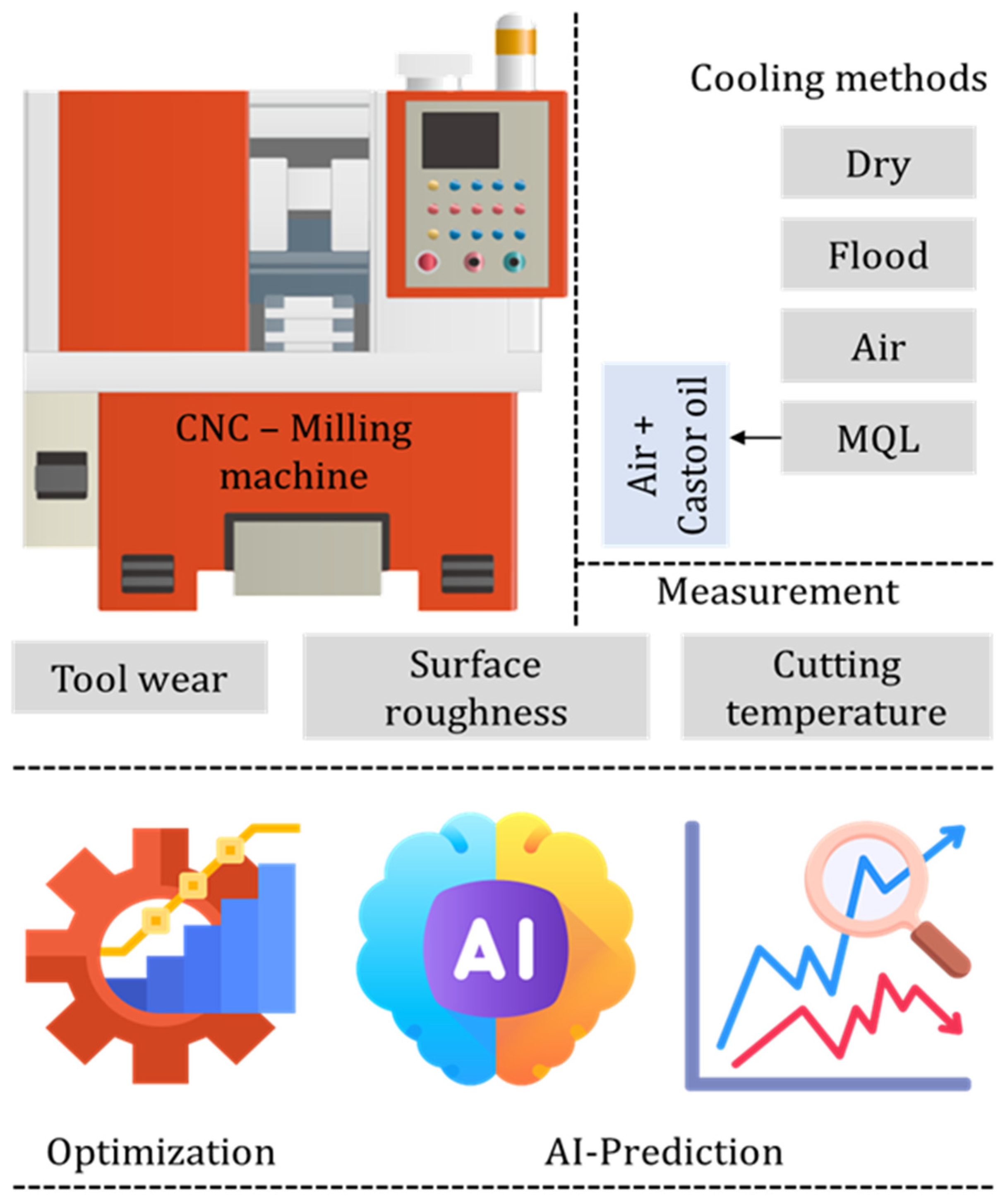
Figure 1. Work flow of this investigation.
Machines 13 00984 g001
Figure 2. (a) Material removal mechanisms and (b) tool wear mechanisms.
Machines 13 00984 g002
Figure 3. Cutting temperature under distinct speed–feed combinations and environments.
Machines 13 00984 g003
Figure 4. Surface roughness under distinct speed–feed combinations and environments.
Machines 13 00984 g004
Figure 5. Depiction of 3D surface plots under distinct cutting environments at a fr of 0.15 mm/rev and Vc of 120 m/min.
Machines 13 00984 g005
Figure 6. Flank wear under distinct speed–feed combinations and environments.
Machines 13 00984 g006
Figure 7. Flank wear under distinct cutting environments at a fr of 0.15 mm/rev and Vc of 120 m/min.
Machines 13 00984 g007
Figure 8. Step by step procedure for MOORA method.
Machines 13 00984 g008
Figure 9. Illustration of process flow of machine learning models.
Machines 13 00984 g009
Figure 10. Schematic of (a) Gaussian Process Regression, (b) Random Forest, and (c) Multi-Layer Perceptron.
Machines 13 00984 g010
Figure 11. Testing and training of (a) GPR, (b) MLP, and (c) RF.
Machines 13 00984 g011
Figure 12. Quantitative analysis of GPR, MLP, and RF.
Machines 13 00984 g012
Table 1. Work details and process parameters.
Milling machineFeeler FV 1000
WorkpieceAlSi10Mg
Dimension (cm)10 × 5 × 1
Insert (tool) coatingWC-TiAlN
Insert ModelAPMT
Length of cut (cm)5 (2 passes)
Speed (m/min)45–60
Feed (mm/rev)0.1–0.20
Radial DOC (mm)12
Axial DOC (mm)2
Table 2. MOORA application.
EnvironmentCutting SpeedFeed RateNormalized (nij)Weighted (kij)PiRank
Dry600.050.19530.20650.19170.06510.06880.0639−0.197828
Dry600.10.20410.21090.19930.06800.07030.0664−0.204831
Dry600.150.20920.21970.20430.06970.07320.0681−0.211134
Dry900.050.19910.19090.20680.06640.06360.0689−0.198929
Dry900.10.20790.19700.21680.06930.06570.0723−0.207232
Dry900.150.21430.20240.23180.07140.06750.0773−0.216236
Dry1200.050.20290.17770.22310.06760.05920.0744−0.201230
Dry1200.10.21300.17810.23310.07100.05940.0777−0.208133
Dry1200.150.21930.18420.23560.07310.06140.0785−0.213035
Flood600.050.16480.18840.16420.05490.06280.0547−0.172519
Flood600.10.17370.19560.17170.05790.06520.0572−0.180323
Flood600.150.17880.20100.17670.05960.06700.0589−0.185525
Flood900.050.16860.17630.17920.05620.05880.0597−0.174721
Flood900.10.17750.17970.18920.05920.05990.0631−0.182224
Flood900.150.18380.18680.19670.06130.06230.0656−0.189127
Flood1200.050.17240.15880.18800.05750.05290.0627−0.173120
Flood1200.10.18260.15230.19800.06090.05080.0660−0.177622
Flood1200.150.18890.16960.20050.06300.05650.0668−0.186426
Air600.050.14330.17270.11650.04780.05760.0388−0.144210
Air600.10.15210.17810.12030.05070.05940.0401−0.150213
Air600.150.15720.18440.12910.05240.06150.0430−0.156917
Air900.050.14710.15710.13160.04900.05240.0439−0.145311
Air900.10.15600.15730.14160.05200.05240.0472−0.151614
Air900.150.16230.16950.14910.05410.05650.0497−0.160318
Air1200.050.15090.14420.14790.05030.04810.0493−0.147712
Air1200.10.16100.14920.15410.05370.04970.0514−0.154815
Air1200.150.16740.14140.15920.05580.04710.0531−0.156016
MQL600.050.10140.12930.08650.03380.04310.0288−0.10572
MQL600.10.10650.13270.09020.03550.04420.0301−0.10985
MQL600.150.11030.14010.09400.03680.04670.0313−0.11487
MQL900.050.10780.11000.09770.03590.03670.0326−0.10521
MQL900.10.11410.11320.10150.03800.03770.0338−0.10964
MQL900.150.11660.12300.10530.03890.04100.0351−0.11508
MQL1200.050.11160.09590.11150.03720.03200.0372−0.10643
MQL1200.10.11790.09960.11400.03930.03320.0380−0.11056
MQL1200.150.12430.10820.11650.04140.03610.0388−0.11639
Disclaimer/Publisher’s Note: The statements, opinions and data contained in all publications are solely those of the individual author(s) and contributor(s) and not of MDPI and/or the editor(s). MDPI and/or the editor(s) disclaim responsibility for any injury to people or property resulting from any ideas, methods, instructions or products referred to in the content.