Abstract
This research presents the first known example of a Thrust-Augmented Rocker Bogie (TARB). As a robust and passive mechanisms, the rocker bogie suspension system has seen widespread application in ground-based robotic planetary exploration rovers. However, with the first demonstration of a multirotor on Mars, there is clearly a need to expand the locomotion capacity for planetary rovers. The TARB builds on the existing flight heritage of the rocker rogie but also innovatively combines the system with a multirotor configuration. The combined homogeneous mobility solution can successfully demonstrate multimodal mobility including in terrestrial, aerial, and hybrid forms of locomotion. The prototype TARB developed for this research was constructed in the form of a CanBot. CanBots provide a means to test space-oriented rover technologies with earth-based analogues. Three prototype multimodal CanBots are described in this work, with each showing improvements in mobility and overall design robustness. Laboratory validation of the final TARB-equipped CanBot showed that it could utilize the rocker-bogie system to engage complicated terrestrial terrains while also maintaining the capacity to fly as an aerial vehicle. The laboratory testing also indicated that the CanBot could climb significantly steeper slopes when employing the TARB in a hybrid mode, successfully climbing slopes of 60 degrees, demonstrating static stability on inclines of up to 90 degrees, and successfully navigating along fully inverted surfaces.
1. Introduction
The exploration of planetary surfaces using mobile robots has many significant and complex design goals. Planetary surfaces are inherently unstructured, rugged, unpredictable, and dynamic. These characteristics make the design of mobile robots for exploring such terrains particularly challenging, often necessitating innovative approaches for success. As part of its Innovative Advanced Concepts Program (NIAC), NASA identified a number of “Space Technology Grand Challenges” including that of “All Access Mobility” [1]. Although considerable time has elapsed since these Grand Challenges were established, there has still only been limited innovation in locomotion solutions for planetary surface exploration.
Additionally, new challenges have arisen for robotic planetary surface exploration that may require novel exploration modalities. One notable example includes subterranean structures such as caves and lava tubes. Such structures, which are well known on Earth, have now been found on planets such as Mars or even as close as Earth’s moon [2]. These geologic features are of particular interest to planetary scientists as they may provide a means to mitigate exposure to radiation and asteroid impacts for future lunar and martian outposts [3]. However, to date, planetary surface-exploring robots have been largely limited to relatively flat and open surface environments. This research proposes and validates a novel form of a multimodal rover which is intended to expand planetary exploration to these kinds of more complex environments.
1.1. Historical Planetary Exploration
The exploration of planetary surfaces using mobile robotic vehicles began in 1971 when the former Union of Soviet Socialist Republics (USSR) successfully deployed an eight-wheeled rover called Lunokhod 1 to the surface of Earth’s Moon. A second Lunokhod rover was also successfully operated on the Moon as well a few years later. However, it would not be until 1997 that a uniquely novel wheeled rover would be successfully deployed to the surface of a different planet. The Sojourner rover, featured in Figure 1a, was developed by NASA as a secondary mission payload on the Pathfinder lander. The rover employed a new mobility approach known as the rocker-bogie suspension system [4]. Since its successful demonstration with Sojourner, the rocker-bogie system has seen widespread usage in additional planetary surface rovers, including notable missions such as the Mars Exploration Rovers (MERs) in 2004, Mars Science Laboratory (MSL) in 2012 [5], and the Mars 2020 Rover in 2021 [6].
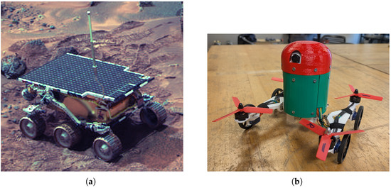
Figure 1.
Comparison of (a) original rocker-bogie system on Sojourner rover [7] to (b) advanced new Thrust-Augmented Rocker Bogie (TARB) CanBot [8].
The rocker-bogie mechanism is a springless and passive system which acts to maintain stability for wheeled planetary rovers by evenly distributing the weight of the rover across all the wheels, even while climbing over large obstacles. Typical rocker-bogie configurations feature a passive differential mechanism connected to two rocker arms on each side of the vehicle. These arms can spin freely, but in opposite directions. Additional passively driven bogies may be attached to the rocker arms to accommodate more wheels, which increase the amount of surface area in contact with the ground [9]. Ultimately, the rocker-bogie system has demonstrated exceptional success and continuing flight heritage in the domain of robotic planetary exploration; however, there are some notable shortcomings.
While the passive nature of the rocker-bogie system provides the benefit of simplicity and robustness, it also comes at the cost of limiting mobility recovery modes. In particular, situations have arisen where rovers equipped with the rocker-bogie system have experienced sand entrapment where the wheels dug themselves deeper into a low-density regolith instead of providing forward locomotion [10]. This failure mode was a significant contributing factor in the eventual death of both MERs [5]. Actively Articulated Suspension systems are being developed to accommodate for this shortcoming by providing a means to independently lift each wheel of the mobility system. Configurations for these systems vary from the SherpaTT test rover that had five degrees of freedom for each wheel [11] to the prototype VIPER rover which maintained three degrees of freedom for each of the four wheels [12]. However, significant additional mechanics, sensors, and software must be developed to support such systems, with only limited additional benefits to the mobility capacity. Such mobility advances include only the capacity to lift individual wheels out of entrapment and the potential coordination of lifting and rotating maneuvers to allow a planetary rover to ‘walk’ or ‘crab’ on its wheels [10,12,13].
While ‘crabbing’ has yet to be used widely in actual planetary surface exploration, the successful deployment of the first heavier-than-air rotorcraft to Mars in 2021 demonstrated that flight on other planets may be a revolutionary new way to explore. The Ingenuity Mars Helicopter, featured in Figure 2, was created as a technology demonstration and added as a secondary payload to the larger Mars 2020 Perseverance mission [14]. The vehicle utilized two counter-rotating coaxial propellers to achieve flight in the thin Martian atmosphere and was able to complete multiple scouting flights that collected data to help the larger Mars 2020 rover navigate [15]. The significant positive outcomes of this mission continue to encourage the development of additional aerial vehicles for exploring planets like Mars [16].
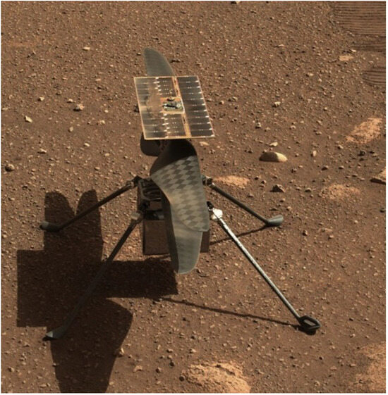
Figure 2.
Ingenuity rotorcraft on surface of Mars [17].
1.2. Multimodal Mobility
As the aerial age begins to dawn for planetary surface exploration, various new forms of locomotion should be considered to enhance the ability of robots to access previously inaccessible terrains. Of particular interest are the so-called ‘multimodal’ approaches, which combine multiple forms of locomotion into a single robotic mobility solution. The fusion of aerial and terrestrial locomotion techniques has been explored extensively by other researchers, with several archetypal categories identified by Kalantari et al. [18]. Among these categories, so-called ‘Active Wheeled’ solutions have been identified as the most feasible for near-term deployment in space environments, as they can potentially be adapted directly from existing mission profiles.
In an Active Wheeled multimodal system, an aerial vehicle, such as a multirotor, is combined directly with motorized wheels to facilitate both aerial flight and terrestrial driving [18]. As both monomodal motorized ground rovers and aerial multirotor aircraft have now been separately demonstrated in planetary surface-exploring missions, the integration of these locomotion approaches into a singular strategy represents a logical evolutionary direction.
This research further categorizes Active Wheeled multimodal approaches into heterogeneous and homogeneous designs. In the heterogeneous configuration, the mechanisms for demonstrating aerial and terrestrial locomotion may be separated distinctly as independent mobility solutions. In many cases, a single plane could be drawn that would separate the heterogeneous multimodal vehicle into distinct aerial and terrestrial sub-vehicles, where either of these sub-vehicles could operate successfully without the other. A few notable examples of heterogeneous designs include the Hybrid Exploration Robot for Air and Land Deployment (HEARALD) [19], the Air–Ground Amphibious Robot (AGAR) [20], and many others [21,22,23].
In contrast, homogeneous designs fully integrate the thrust generation needed for the aerial system into the terrestrial wheeled mobility, making it impossible to separate the two subsystems. The degree of integration between terrestrial and aerial locomotion is often so significant that they are used in tandem to aid mobility. One example of this relationship includes the Multi-Modal Mobility Morphobot or M4 developed by Sihite et al., which utilized ducted fans modified to allow the shrouds to act as wheels. By also mounting the modified ducted fans on the ends of two-degrees-of-freedom arms, the M4 could demonstrate aerial flight, terrestrial driving, and various hybrid mobility techniques. One such specialized climbing technique involved configuring two of the four propellers/wheels to drive up a slope while the other two were configured as propellers [24].
Homogeneous configurations for the Active Wheeled multimodal systems are noteworthy due to their potential for mobility efficiency. By fully integrating the terrestrial and aerial mobility approaches, redundant mechanisms and systems may be eliminated. Reducing system complexity and increasing mobility efficiency are essential for developing mobility solutions that will be feasible for planetary exploration, where power is often a limited resource, and robust mobility designs are required. Efficiently combining the mobility systems is exemplified by robots such as Drivocopter, a rover prototype that enclosed propellers inside spherical cages, enabling the cages to act as spherical wheels [18], and FCSTAR, a small ‘sprawling’ robot that directly powered the wheeled mobility system using the same motors used to drive the aerial multirotor system [25]. Figure 3 compares notable examples of heterogeneous versus homogeneous multimodal designs. Examples of the most relevant active wheeled multimodal robots are compiled in Table 1.
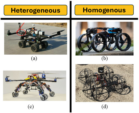
Figure 3.
Comparison of homogeneous and heterogeneous multimodal, including (a) AGAR [20], (b) M4 [24], (c) H.E.R.A.L.D [19], and (d) Drivocopter [18].

Table 1.
Compilation of mulitmodal active wheeled robots.
1.3. Multimodal in Space
Although not explicitly multimodal, active suspension systems represent an important step toward increasing the mobility effectiveness of planetary rovers. NASA’s VIPER rover was intended to engage new lunar terrains with one of the first wheeled mobility systems to not include any passive elements, a major departure from the traditional rocker-bogie technique [12]. Furthermore, the recent Chinese rover known as Zhurong demonstrated successful mobility on the surface of Mars in 2021 using a unique mobility system [13]. In addition to having a standard six-wheeled rocker-bogie system, Zhurong also had the capability to lock the differential mechanisms between the rocker arms and adjust the height of the suspension system for the purpose of lifting the cab and wheels [10]. This is the first and only known space deployment of an active suspension system capable of demonstrating multi-mode terrestrial locomotion capabilities.
The marked success of the Ingenuity rotorcraft, another rover that found success on Mars, has led NASA to consider using a similar robotic vehicle for the upcoming Mars Sample Return Mission. Initial renderings and engineering models of this updated vehicle known as the Sample Fetch Helicopter (SFH) appear to show a coaxial rotorcraft similar to Ingenuity fitted with wheels on its landing gear. The rover includes the multimodal aspect because it will need to both fly long distances quickly between the cached Mars Sample Tubes and the Mars Ascent Vehicle, while also demonstrating precise terrestrial navigation to get close enough to the tubes to collect them. If such a rover proceeds to deployment and use on Mars, it may be the first example of a multimodal planetary surface exploration robot [26,27].
Based on the previously analyzed literature, this research makes a number of key contributions to the field:
- Development of fully homogeneous multimodal locomotion technique targeted for deployment in planetary surface environments;
- Significantly improved capacity for rocker-bogie system to climb inclines well beyond any previous rover configurations;
- Unique hybrid locomotion mechanism that allowed for fully inverted operation of a rocker bogie.
2. Materials and Methods
The following section describes the development and testing of the proposed Thrust-Augmented Rocker Bogie.
2.1. CanBots
To provide a means for initially validating the TARB, in anticipation for future deployment to space environments, prototype vehicles were developed as CanBots. Much like their counterpart CanSats, CanBots are intended to be used as terrestrial analogs for small-scale planetary exploration robots. CanSats have largely been leveraged for simulating orbital CubeSat technologies while CanBots are oriented toward simulating surface exploration vehicles like micro- and nano-scale planetary rovers [28].
CanBots still represent an emerging field of study, which is also true of their planetary exploration equivalents. Small-scale planetary rovers have gained popularity in recent years as secondary mission payloads on many private lunar lander missions [29,30,31]. Planetary Robotics company Astrobotics has begun to develop a small-scale and modular design standard for a planetary rover which they call the “CubeRover” [32]. This design standard has yet to gain wide acceptance but is clearly attempting to translate the success of the CubeSat paradigm to the planetary rover domain.
To maintain some coherence with the apparent trends in small-scale planetary rovers, a similar modular design approach was adopted. The core tenants of this design system were initially developed for use in modular CanSats but have now been adopted for application in the CanBot field [33]. Noteworthy aspects of this design approach include the use of Commercial Off-The-Shelf (COTS) hardware and interchangeable modular parts to aid in rapid prototyping and iterative improvement strategies. This technique facilitated the development of many CanBot vehicles that helped inform the design of the final TARB.
Significant CanBots that directly informed the eventual development of the TARB included the creation of Vertically Oriented Quadrotor designs and multiple forms of rocker-bogie-equipped CanBots. Additionally, the creation of the initial multimodal prototypes that utilized other varieties of locomotion helped to establish the necessity for the configuration of the TARB. The following subsections describe some of these contributing vehicles in more detail.
2.2. Initial Multimodal CanBot
One such CanBot that demonstrated the capacity for multiple forms of locomotion included the Quadruped–Quadrotor design, or simply quadrupedal–rotor for short. This design allowed for the first heterogeneous combination of separate CanBot mobility modules. By leveraging the creation of two separate and distinct CanBot vehicles, namely, a quadrupedal design and a quadrotor design, the combined multimodal approach could be fabricated. Additionally, the presence of each individual mobility configuration as distinct CanBot vehicles allowed for a direct comparison of the multimodal approach to each existing monomodal locomotion technique [34].
Figure 4 illustrates the individual monomodal CanBots that were combined into the final multimodal configuration. In this case, a distinct aerial quadrotor CanBot, featured in Figure 4a, and a CanBot fitted with a terrestrial and quadrupedal chassis, depicted in Figure 4b, were the basis for the multimodal system included in Figure 4c. A supplemental video of the CanBot operating can be found here [35], and an in-depth study was conducted, using a Motion Capture (MoCap) system to characterize the mobility differences between the monomodal and multimodal CanBot. Notable outcomes from this study included a change in the walking gait and an increase in power consumption for the multimodal system when compared to the monomodal approaches [34].
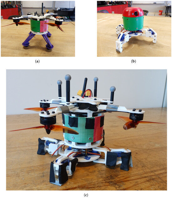
Figure 4.
Monomodal CanBots including (a) quadrotor CanBot and (b) quadruped CanBot utilized to construct (c) an initial multimodal ‘quadruped–rotor’ CanBot [34].
2.3. Heterogeneous Design Development
Similar to the quadrupedal–rotor CanBot, combining an aerial quadrotor with the terrestrial rocker bogie initially utilized a heterogeneous approach. As before, monomodal CanBots, representing each distinct locomotion approach, were first developed separately. These separate mobility modules were then later combined into a single CanBot that could demonstrate both forms of locomotion. Figure 5 features both monomodal vehicles and the combined heterogeneous rocker-bogie quadrotor CanBot. Notably, the monomodal quadrotor CanBot, which was created as a pathfinder for the heterogeneous design, employed symmetric propellers to allow for bidirectional thrust. This vehicle also leveraged a SpeedyBee F7 V3 (Zhuhai KuaiFeng Technology Co, Zhuhai, China), which is a COTS flight controller (FC). After reconfiguring the flight controller for “3D” mode and reprogramming the 4-in-1 Electronics Speed Controller (ESC) board included with the FC, this quadrotor CanBot was able to demonstrate both normal flight modes as well as reversed thrust capabilities, which would be necessary for the heterogeneous design. The monomodal rocker-bogie CanBot, whose mechanics were eventually incorporated into the heterogeneous design, utilized simplified mechanisms based on a central control arm. This arm was mechanically linked to each side of the rocker mechanisms through ball joints, which allowed for a limited range of differential averaging between the rocker arms. Each rocker arm was equipped with two continuous rotation servos, modified to have stronger and more robust metal gears. The full array of four servos were then controlled by an Arduino Nano (Arduino SA, Chiasso, Switzerland).
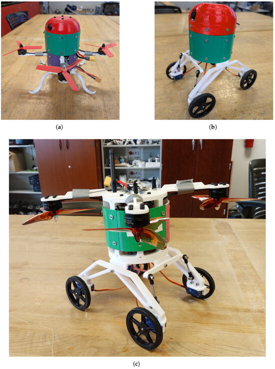
Figure 5.
Monomodal CanBots including (a) Quadrotor 2 CanBot and (b) Cross-Arm Rocker-Bogie CanBot utilized to construct (c) the initial heterogeneous rocker-bogie quad CanBot.
When combining these two modules, two configuration of the robot were generated. In the first configuration, the FC was maintained in the quadrotor module and the Arduino Nano was maintained in the rocker-bogie module. This initial CanBot design allowed the CanBot to separately demonstrate both aerial and terrestrial locomotion. To configure the robot for a hybrid mobility mode, the FC and ESC board from the aerial CanBot was removed and replaced with discrete ESCs. These controllers were reprogrammed in the same way as the 4-in-1 board but could be controlled more easily by the Arduino Nano. This was necessary as the standard BetaFlight firmware for the FC could not be reprogrammed at this time to eliminate self-stabilization modes. The second configuration of the heterogeneous rocker-bogie quadrotor design was able to successfully achieve a hybrid mobility mode in addition to demonstrating both aerial and terrestrial locomotion separately. In the hybrid mobility mode, both the terrestrial and aerial locomotion techniques were used in conjunction to allow for unique additional mobility capability. In this case, the hybrid approach allowed this CanBot to climb an inclined surface in excess of its static stability limit.
2.4. Homogeneous Design Development
By employing some significant lessons learned from the heterogeneous designs, the homogeneous design made a number of key improvements. Firstly, this approach significantly lowered the center of gravity for the CanBot to improve the general stability of the model. Second, the homogeneous design was still largely informed from the creation of separate monomodal CanBots, but the mechanics for those robots were fused to create single homogeneous mobility designs. The fusion of the rocker-bogie and quadrotor concepts was completed by mounting the thrust-generating propellers directly on the ends of the rocker arms. This created a system where the propellers were fixed directly to and located in close proximity with the wheels of the rocker bogie. To maintain enough clearance for the spinning propellers, the rocker arms were also flattened significantly and mechanically coupled using a differential gearbox instead of the sequence of control arms. The differential gearbox-based rocker-bogie approach is more commonly utilized for planetary surface-exploring robots and was first trialed as a discrete mechanism in another CanBot featured in Figure 6.
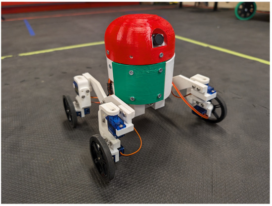
Figure 6.
Differential Gearbox-based rocker-bogie CanBot [8].
For terrestrial locomotion, the homogeneous design utilized the same continuous rotation servos developed for the heterogeneous design, with each of the four servo wheels mounted at the four corners of the rocker arms. With the passive differential mechanics coupling both control arms, the CanBot could successfully climb obstacles up to approximately the diameter of the wheels. As before, the driving motors on the CanBot were controlled by a separate Arduino Nano and Radio Frequency (RF) link. To achieve the aerial mobility mode, the SpeedyBee FC was reflashed with iNav firmware which allowed for multiple mixes and Proportional–Integral–Derivative (PID) profiles to be programmed onto the FC. The first profile was left configured for standard quadrotor flight mechanics, while the second mode was modified to directly control each of the propeller motors with PID gains set to zero. Further mechanical additions were also made to the differential gearbox to aid the flight mode, namely the inclusion of a custom mechanical clutch to arrest the mechanism at will.
As the propellers were now attached to the rocker arms, they could rotate freely along with the rocker arms. In an ideal-level flight mode with a perfectly balanced vehicle, the CanBot may have been able to fly in this configuration. However, with any imbalance, or particularly for yaw maneuvers where alternating propellers on opposite corners of the rocker arms are throttled up, would cause the vehicle to become unstable. Therefore, the mechanical clutch was an important feature for the flight mode. Figure 7 illustrates the relationship between the clutch and the differential gearbox. This clutch was constructed by leveraging a third shaft in the differential gearbox. Each rocker arm was connected to a shaft that terminated in a bevel gear. Each of these bevel gears were arranged on opposite sides of the gearbox in mirrored orientations. Between these two bevel gears was a third gear which provided the means for transferring mechanical force from one rocker arm to the other. The shaft for this third gear was extended to beyond the edge of the gearbox, and an additional pinion gear was attached to the end of the shaft. Three-dimensional printed pawls were then created to grab the pinion gears, and two such pawls were affixed to the horns of two metal geared servos. By rotating the pawls into the pinion gear, the differential gearbox could be mechanically arrested for flight.
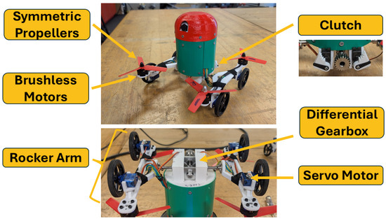
Figure 7.
TARB design in detail [8].
The servos controlling the pawls were connected to the Arduino Nano utilized for the terrestrial mode. Once the clutch was locked, the regular flight mode on the FC could be utilized to manually fly the CanBot as an aerial quadrotor. Then, with the clutch unlocked and the FC set to the second flight mode, the vehicle could also be operated in the hybrid mode. In this hybrid mode, the thrust for the propellers was reversed, while the rocker bogie could be used to climb over obstacles on the surface of the vehicle was climbing. Pertinent design information for the TARB can be found in Table 2. Additional design details and reference codes for all relevant CanBots have been compiled in Table 3.

Table 2.
TARB design specifications.

Table 3.
CanBot configurations.
2.5. Wheel Slippage Testing
Wheel slippage as a function of an inclined slope was identified as a preferable means for quantifying mobility effectiveness. This quantification technique has been previously utilized for wheeled planetary surface rovers from the Mars Exploration Rovers (MERs) [36] to more modern systems such as the Mars Science Laboratory (MSL) [37].
2.5.1. ATAT Table
To provide a consistent testing surface, the Analogous Terrain And Tilt table or ATAT table was developed. This test bed featured a relatively smooth Oriented Strand Board (OSB) surface that could be remotely inclined from zero to 90 degrees. The choice of the OSB surface was purposeful, to provide a worst-case scenario where frictional coefficients would be relatively low. In a real-world planetary surface, which could comprise of rock, sand, or other earthy substrates, the tractive forces would be expected to be higher on average than the particle board surface. Determining the coefficient of sliding friction for the table surface and rubber tires of TARB was completed by dragging a calibrated mass across the level surface of the ATAT table. To ensure a constant dragging velocity and a straight dragging path, an electric linear actuator and sliding rail were developed to drag the calibrated mass across the table surface. The four tires for the TARB were further affixed to the calibrated mass in such a manner as to not allow any rotation of the tires. To measure the frictional force as the calibrated mass was pulled across the table, a Pasco PS-2104 force sensor (Pasco Scientific Inc, Roseville, CA, USA) was affixed between the linear actuator and the calibrated mass. Once an average force was determined, the following formula was employed to determine the coefficient of sliding friction .
where ‘F’ represents the measured drag force, and ‘N’ was determined through the product of the calibrated mass and the local gravitational acceleration. Through this means, the average frictional coefficient for the table surface was determined to be 0.71. Since the dynamics of climbing the table surface were known to be more complex than a translational frictional coefficient could express, this value has been included as a general reference but was not directly employed for determining the wheel slippage later. The computational approach for determining wheel slippage is included in the results section.
The ATAT table was further equipped with digital inclinometers which could be remotely read using a camera system. One inclinometer was arranged to measure the incline of the test surface, while the other was arranged perpendicular to the first to make sure the surface was relatively level in the perpendicular direction. An example of the ATAT table in an inclined configuration is included in Figure 8.
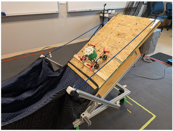
Figure 8.
TARB CanBot climbs partially inclined ATAT table.
Remote operation of the ATAT table was also a significant design criteria, as many of the CanBots being tested included spinning propellers that could pose a risk to the researchers. By starting with the table in the level position, the propellers on the CanBots could be armed and used to stabilize the vehicle while the surface of the table is inclined to the desired testing angle. Additionally, a safety blanket was also attached to the ATAT table to catch CanBots if they fell off the table. This functionality was important to arrest any propellers and to cushion the fall of the CanBots in the event of a premature failure of the mobility system.
2.5.2. Motion Capture
In addition to providing controllable angled surfaces to climb, the experimental process also leveraged an advanced Motion Capture (MoCap) system to measure the displacement of the CanBots. Utilizing an arrangement of eight OptiTrack Flex 3 Cameras (NaturalPoint Inc, Corvallis, OR, USA) mounted to the walls of the laboratory, and arrays of retro-reflective markers mounted to the CanBots, the robots could be localized to millimeter accuracy. Each CanBot was first trialed on the flat ATAT table to provide a benchmark for a zero-slip condition. Then, the surface of the ATAT table was gradually increased until the CanBot either fell off the surface or failed to continue climbing. Data from the MoCap system was then exported as CSVs and analyzed with a custom program in MATLAB 2023B. The following section describes these outcomes and provides more details about these experimental results.
3. Results
Wheel slippage for the CanBots was ascertained by first reconstituting the trajectory of each test run using the MoCap data. This data provided a means for ascertaining the approximate slope of the movement trajectory and the distance traveled by the CanBots. The distance traveled was then compared to the baseline value measured while the ATAT table was level. To determine wheel slippage, the same equation used to characterize the wheel slippage of a prototype MSL rover was employed:
This equation, utilized by Heverly et al. at NASA’s Jet Propulsion Laboratory (JPL), compares the actual traveled distance, , to the distance the rover was commanded to move, [37]. To determine the measured distance, both for the actual and commanded values, a general three-dimensional distance formula was employed:
where were the starting coordinates of the robot and were the final coordinates of the rover, all recorded by the MoCap system. By determining the displacement of the rover when the table was flat, the measured zero-slip distance could be computed with Equation (3). Then, the distance traveled at each level of inclination could also be computed with the same equation. Employing these measured distances with Equation (2) allowed the wheel slippage to be computed and then later compared to the amount of slope the vehicle climbed. The first set of data analyzed in the following section focuses on the heterogeneous CanBot design.
3.1. Heterogeneous CanBot Results
The initial heterogeneous combination of the rocker-bogie and quadrotor capabilities was tested and validated in a number of approaches. Firstly, the general locomotive capability of the vehicle was analyzed qualitatively, before more in-depth quantitative analyses of the wheel slippage were completed. The mobility analysis is presented first in the next section.
3.1.1. Heterogeneous Mobility Validation
In its first configuration, the heterogeneous CanBot was able to demonstrate separate terrestrial and aerial mobility capabilities. This included the capacity to drive along the ground using the rocker bogie, in addition to flying in the air as a multirotor, as demonstrated in [35]. Notable shortcomings of this design were observed during this testing process, including the relatively high center of gravity, which severely limited the ability for the CanBot to engage obstacles. Another major shortcoming was the inability to disable the automatic stabilization of the quadrotor, which initially precluded the ability to demonstrate the hybrid mobility mode.
During initial ATAT table testing, this later shortcoming proved to be of particular concern. While some attempts were made to manually correlate the desired angle of the CanBot with the stabilization angle targeted by the FC, this proved to be impractical during testing. This shortcoming necessitated the creation of the second configuration of the heterogeneous rocker-bogie CanBot. With the updated configuration, the vehicle could still drive and fly, but the capability for precise aerial maneuvering was lost with the replacement of the SpeedyBee FC. Testing of this configuration focused primarily on the feasibility of the hybrid mobility mode, and therefore, it largely utilized the ATAT table in various inclines. To minimize additional variables, the hybrid mobility mode was configured for maximum propeller thrust through all tested inclines. This convention was also employed for the later tested homogeneous design. Although this approach was known to cause inefficiencies for the less steep inclines, developing control techniques for the propeller thrust was determined to be beyond the scope of this research.
3.1.2. Heterogeneous Wheel Slippage
Testing of the second configuration of the heterogeneous design on the ATAT table necessitated the creation of a basic preprogrammed driving trajectory. This trajectory was added to the Arduino Nano and could be triggered at will by the pilot of the CanBot using a switch on the controller. The driving program initially directed the wheels to run continuously for a set period of time after receiving the relevant RC control signal. Later versions of this program developed for the homogeneous design gradually increased the speed of the wheels to reduce startup slippage.
Raw trajectory data for this CanBot is presented in Figure 9, while the computed wheel slippage for the rover is compiled in Figure 10. The first five test runs featured in these figures included inclines of between zero and approximately twenty degrees. For these tests, the heterogeneous rocker-bogie CanBot was able to climb the surface of the ATAT table without any thrust augmentation. These initial test runs are plotted as blue lines. Notably, based on the estimated center of gravity for the CanBot and the computed support polygon, the vehicle was expected to loose static stability at approximately 30 degrees of incline. However, the experimental testing found that the dynamic stability of the system became compromised at inclines exceeding approximately 20 degrees. Beyond that threshold of dynamic stability, the propellers were engaged with the thrust pointing away from the surface of the table so as to push the CanBot onto the surface. Trajectories of the heterogeneous CanBot design with the propeller augmentation engaged have been plotted in red for both figures. With this augmentation, the CanBot was able to continue to climb the slope beyond the point of static instability, reaching a maximum climbing angle of approximately 40 degrees. Figure 10 correlates the slope angle with the percent slippage of the wheels. Notably, the slippage percent increased regularly from zero to twenty degrees before suddenly decreasing as the thrust augmentation was engaged. Table A1 summarizes the results from both plots and indicates the measured travel distance of the CanBots and the mechanisms for determining the climbing angle.
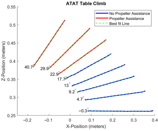
Figure 9.
Heterogeneous CanBot incline trajectory tracking [8].
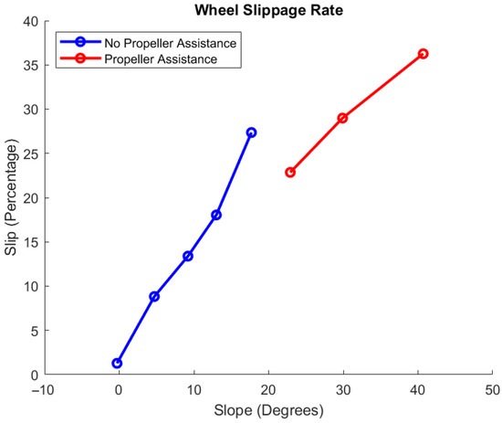
Figure 10.
Heterogeneous CanBot wheel slippage [8].
3.2. Homogeneous CanBot Results
In a similar fashion, the homogeneous Thrust-Augmented Rocker Bogie equipped CanBot was also tested in the various independent locomotion modes in addition to conducting hybrid locomotion experiments with the ATAT table.
3.2.1. Homogeneous Mobility Validation
To demonstrate both terrestrial and aerial mobility, first, the ATAT table was fitted with artificial rocks and TARB was tested with the differential clutch unlocked and the table in a level position. These tests, illustrated in Figure 11, showed that the rocker-bogie mechanisms operated as expected and allowed the vehicle to terrestrially traverse obstacles of a significant size. Aerial validation of the TARB was completed in a safe and controlled laboratory environment where the differential clutch was first locked and then the onboard FC set to a standard quadrotor flight profile. These tests indicated that the system was able to successfully hover and maneuver as a multirotor vehicle. Combined motion tests were also undertaken where the TARB was first driven terrestrially, then remotely reconfigured for flight mode to allow the rover to overcome very large obstacles [35]. These trials indicated that the system was capable of demonstrating chained actions, moving between terrestrial, aerial, and hybrid modes without the need for external modification.
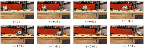
Figure 11.
CanBot uses rocker bogie to climb over rocks [8,35].
In addition to the ATAT-Table incline testing described later and featured in Figure 12, the final and most extreme mobility validation for the TARB involved fully inverting the vehicle with the thrust augmentation active. In this test, the homogeneous TARB demonstrated the capacity to stay adhered to the moving surface of the improved ATAT table to the point of complete inversion of the CanBot. Figure 13 displays an image sequence of the TARB successfully moving along the inverted surface of the ATAT table. In this mobility demonstration, the TARB was also successful in overcoming a small obstacle attached to the surface of the inverted table. This demonstration showed the unique mobility capacity of the TARB to engage inverted wheeled operation, with the rocker-bogie system operating successfully to facilitate rolling over obstacles. Additional inverted trials for the TARB design can be found in [35].
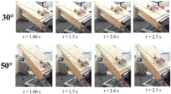
Figure 12.
CanBot in hybrid mode climbing ATAT table [8,35].

Figure 13.
CanBot in hybrid mode successfully climbs over object on inverted ATAT table [8,35].
3.2.2. Homogeneous Wheel Slippage
Incline testing of the homogeneous TARB followed the same general experimental approach as the heterogeneous system, as shown in Figure 12, where an image sequence of the TARB climbing the ATAT table is included. The trajectory data measured for the TARB-equipped CanBot is compiled in Figure 14. With the homogeneous design, the CanBot was able to climb a slope in excess of thirty degrees without requiring the addition of the thrust augmentation. Notably, once the thrust argumentation was engaged, the slippage rate at a slope of thirty degrees was greatly decreased from approximately 80 percent to around 40 percent. As before, the blue lines represent data collected without thrust augmentation, while the red lines represent tests where the propellers were active. With the addition of the thrust augmentation, the CanBot was able to further climb slopes of up to 60 degrees and was able to still maintain contact with the sloped surface up to inclines of 90 degrees. However, at the maximum incline of 90 degrees, the CanBot was unable to successfully climb the surface of the table.
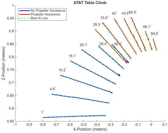
Figure 14.
Homogeneous CanBot incline trajectory tracking [8].
Figure 15 further expands the analysis of this data to indicate the wheel slippage rate as a function of the inclined slope. Similar to the heterogeneous approach, note how the slippage rate increases regularly before the thrust augmentation was engaged, and then decreases drastically with the addition of the thrust. Also notable from this data was an apparent significant increase in wheel slippage at the 50-degree incline point. This may represent the maximum useful slope that the TARB can feasibly climb without significant slippage. Table A2 summarizes all numerical results for the homogeneous design.
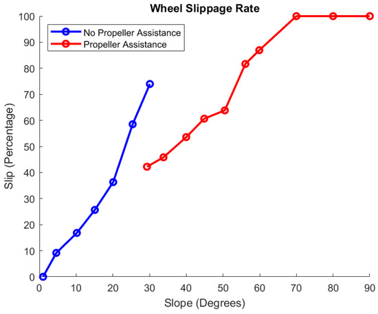
Figure 15.
Homogeneous wheel slippage [8].
3.2.3. Power Logging
To provide an additional metric for mobility quantification, data concerning the power consumption of the homogeneous TARB design was also collected. Power consumption was determined as the product of the voltage and current supplied to the CanBot, with the voltage measured using a Pasco PS-3211 sensor and current measured using a shunt resistor and the Pasco PS-2160 Galvanometer. As this power logging equipment occupied significant space and presented an overly cumbersome burden to the CanBot, a 10-gauge power umbilical was employed to connect the CanBot to the power logging equipment. As this necessitated moving the battery for the CanBot to the same external location as the power logging equipment, weights were added to the vehicle that were equivalent in mass to the battery used in the previous tests. This ensured that the CanBot maintained the most consistent mobility characteristics that was possible between the different tests.
As with the previous incline testing, the CanBot was programmed to drive a set distance along the surface of the ATAT table. For the first battery of tests, the propellers remained deactivated, with the robot moving only in the terrestrial mobility mode. The surface of the table was inclined between each test, providing a gradually increasing slope that the robot was directed to climb using the maximum wheel speed it was capable of. The voltage and current data generated by this experimental process is included in Figure 16, with the voltage plotted as the orange lines and the current as the blue. Notably, there was a small lag noted between the Rising Edge (RE) of the current and Falling Edge (FE) of the voltage. As Ohm’s law would predict that these events should be correlated, for an assumed constant resistance of the motors, the RE and FE were tagged in the data and synchronized, as featured in Figure 17. Once the voltage and current data was successfully resynchronized, the power consumption for the CanBot could be computed for each level of incline as depicted in Figure 18. In this figure, the red boxes mark the period of time when the CanBot was climbing the surface of the table. As would be expected, the increased degree of inclination resulted in greater power consumption. This data was also used to determine how much power the CanBot required while not actively climbing the incline, as marked with the blue boxes.
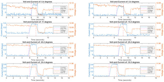
Figure 16.
Voltage and current plot for homogeneous TARB, prior to synchronization [8].
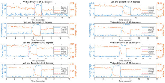
Figure 17.
Voltage and current plot for homogeneous TARB, after synchronization, without propeller augmentation [8].
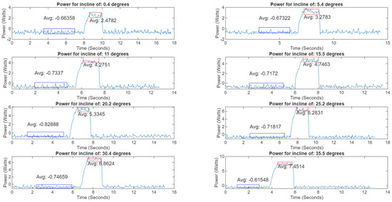
Figure 18.
Power plot for homogeneous TARB without propeller augmentation. Blue boxes indicate power consumption while idle before climb, red boxes indicate power consumption during incline testing. [8].
In conjunction with the power logging equipment, the MoCap system was also utilized during these tests to record the position of the CanBot. This data was leveraged to determine a more accurate value for the angle climbed, as with the previous test, but the derivative of the positional data was also computed to ascertain the velocity of the vehicle during the climb. This instantaneous velocity data is presented in Figure 19 for each level of incline tested. For each climb test, the CanBot was allowed to reach a constant climbing velocity, which has been identified with the red boxes on each of the plots. Averaging this constant velocity section of the CanBot’s climbing data provided a means for computing the Cost of Transport (COT) for the CanBot in conjunction with the previously established power data. Since COT provides a means for comparing the energy required to move a mass at some speed, it was a convenient measure of efficiency for the CanBot. The following equation was used to determine the COT:
where “P” represents the electrical power consumed or the product of the voltage and current required for locomotion. The value “W” indicates the weight of the robot, a product of the gravitational acceleration, taken to be 9.81 m per second squared, and the mass, measured to be 1.01 kg for the homogeneous TARB, including its battery. Finally, “V” stands for the velocity of the system. Using this equation, the COT could be computed using the average velocity and the average power consumed during each of the incline tests. All of these results for the homogeneous TARB without thrust augmentation are compiled in Figure 20.
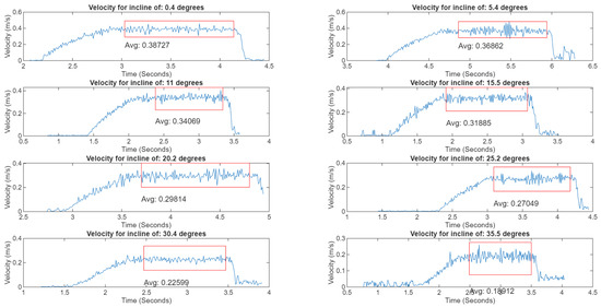
Figure 19.
Velocity plot for homogeneous TARB without propeller augmentation. Red boxes indicate region of averaged constant velocity [8].
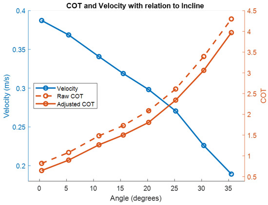
Figure 20.
Comparison of velocity and COT for different inclines for the homogeneous TARB without thrust augmentation [8].
Using the previously determined power consumed by the CanBot while idle, the COT was adjusted to represent only the energy required to actually move the robot. The expected trend of COT increasing as the angle increased was observed. Similarly, a decrease in velocity was also noted to occur as the incline increased. At the highest velocity, approximately 0.39 m per second, the CanBot demonstrated the best COT of 0.65. To complete the testing for the homogeneous TARB, the same testing process was completed with the thrust augmentation active. As indicated by the previous wheel slippage results, the activation of the thrust augmentation allowed significantly larger degrees of inclination to be engaged. As before, the position of the CanBot was recorded using MoCap and then the derivative was taken to ascertain velocity. Similarly, the current and voltage were measured and synchronized using the FE and RE technique, and the product was taken to determine the power consumption. The final results for the higher inclinations and the active thrust augmentation are included in Figure 21. Note that the significantly higher COT associated with activation of the thrust augmentation required a different scaling of the COT axis for this figure.
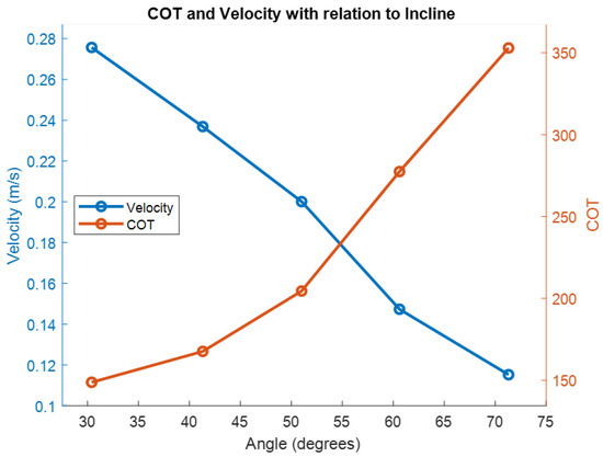
Figure 21.
Comparison of velocity and COT for different inclines for the homogeneous TARB with thrust augmentation [8].
4. Discussion
The Thrust-Augmented Rocker Bogie (TARB) presents a novel innovation to the decades old rocker-bogie system. In its most basic form, the TARB-equipped CanBot was able to demonstrate standard rocker-bogie mechanics, allowing the simulated rover to climb over large obstacles using a terrestrial wheeled locomotion method. However, by also mounting thrust-generating motorized propellers to the ends of the rocker arms and including the capacity to mechanically arrest the passive differential mechanisms, the prototype TARB was also able to demonstrate the capacity to fly. This unique multimodal strategy significantly expands the capacity of a typical rocker-bogie system into the aerial domain, as well as offering unique hybrid locomotion capacities. Reversing the direction of all the propellers allowed the rocker-bogie system to be able to climb inclines of up to 60 degrees, which was well beyond where the vehicle would have lost static stability without thrust augmentation, providing a means to climb very steep slopes. Such performance supersedes standard rocker-bogie approaches, which have generally been limited to climbing inclines of 30 to 40 degrees [4,37]. Additionally, initial experimentation has shown that the TARB can also operate on fully inverted surfaces in this hybrid mode, allowing the wheeled portion of the vehicle to drive over obstacles on the ceiling.
However, comparison of the COT and mass of the TARB to other CanBots developed by the MARS lab reveals some notable tradeoffs in the design. As noted in Figure 22, while in the terrestrial mobility mode, the TARB represents a notably heavier design than the typical rocker-bogie configuration. The extra mass of the TARB, in conjunction with a similar power consumption and speed to the basic rocker-bogie CanBot, resulted in a slighter lower COT for the TARB when in its terrestrial locomotion mode. The lowest COT for the rocker-bogie CanBot was previously determined to be approximately 1.0 at a maximum velocity of 0.4 m/s, while the TARB demonstrated a minimum COT of 0.65 when traveling at a maximum forward velocity of 0.39 m/s [8]. With the TARB operating in the hybrid mode, a significantly different result was demonstrated, with the TARB measured to have a COT of well over 100 for all angles and velocities measured. This indicates that the hybrid mobility mode for the TARB was very energy intensive to use, making it a potentially costly locomotion technique for a future planetary surface rover.
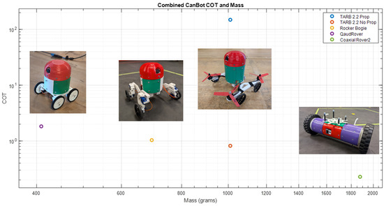
Figure 22.
COT compared to mass for select wheeled CanBots [8].
Future Directions
Additional improvements to the TARB will be made to further increase its mobility effectiveness. In particular, augmenting the tractive capacity of the wheels may allow for steeper inclines to be traversed or more complex obstacle to be engaged. Future testing will have the goal of successfully demonstrating wall climbing and further quantifying the effectiveness of the TARB on inverted surfaces. Successful demonstration of the vehicle in all orientations may allow for testing more complicated obstacles on these inclined surfaces, including the possible addition of simulated rocks to increase the complexity of terrain. Higher fidelity simulations will work towards validating the mobility approach in cave-like structures analogous to those potentially present on the Moon or Mars.
An additional functionality that will be investigated in the future includes the capacity to use single propellers to move only one wheel at a time. Such a functionality could allow for each quadrant of the rocker arm system to be individually actuated with the associated propeller. By providing directional thrust pointed away from the ground, a wheel may be lifted. Similarly, by reversing the thrust, the wheel could also be forced toward the ground. Coordination of this motion could provide similar functional outcomes to the proposed Actively Articulated Suspension systems, where the rover would be able to ‘walk’ on its wheels. Such a mobility approach could presents a unique fault-tolerant technique where an entire locomotion mode may fail and the rover could continue its mission in the other mode. As an example, tests were completed where the gearboxes for the wheeled chassis of the heterogeneous TARB were disabled, but the vehicle was still able to demonstrate terrestrial and aerial mobility by utilizing the propellers [35]. This presents a unique mechanism for a planetary rover to extend its mission even when mechanical elements of the mobility system begin to fail. Future investigations will work toward quantifying the energy cost and mobility effectiveness of these other possible mobility modes.
Additional investigation is also required in quantifying the efficiency and effectiveness of the aerial mode of the TARB CanBot. Although only limited qualitative testing was conducted for the TARB in aerial flight mode, a comparison of the mass of the TARB to the previously developed quadruped–rotor CanBot showed that the TARB maintained a significantly greater mass than the quadruped–rotor. In a previous study, the current consumption of the quadruped–rotor multimodal CanBot was compared to a configuration of the Vertical Quadrotor CanBot. This study indicated that the multimodal system required nearly twice the current to maintain flight with the heavier airframe [34]. A similar trend is expected for the TARB, but further quantification of the specific relationship is needed.
5. Conclusions
A Thrust-Augmented Rocker-Bogie system offers the capacity to maintain the significant flight heritage of the existing rocker-bogie system while also expanding the capacity of the mobility approach with aerial and hybrid locomotion modalities. Such a system can drive on the ground using the passive rocker-bogie system, fly through the air as a multirotor, but also climb complex, uneven, and very steep inclines through hybrid locomotion strategies. Laboratory testing of the prototype homogeneous TARB demonstrated that it had the capacity to climb a relatively smooth surface to an incline of 60 degrees while still showing static stability on that same surface to complete inversion. An analysis of the COT for the TARB suggested that the prototype rover maintained a similar COT to an existing rocker-bogie CanBot when operating in the terrestrial mode. However, while the hybrid mobility mode significancy improved the locomotion capability of the CanBot, the computed COT for the TARB operating in this mode was also determined to be orders of magnitude higher than the terrestrial mode. While this reduces the immediate potential applicability of this locomotion technique for the purposes of planetary surface exploration, the TARB could still provide a unique locomotion solution. Laboratory testing indicated that the system was capable of navigating along a completely inverted surface. Moreover, the TARB was also able to demonstrate successful operation of the rocker bogie while driving along the fully inverted surface. Further development and improvement of the design could empower future multimodal CanBots to successfully explore complex environments like caves and lava tubes.
Author Contributions
Conceptualization, C.C. and M.H.T.; methodology, C.C.; software, C.C.; validation, C.C.; formal analysis, C.C.; investigation, C.C.; resources, M.H.T.; writing—original draft preparation, C.C.; writing—review and editing, C.C.; supervision, M.H.T.; project administration, M.H.T.; funding acquisition, M.H.T. All authors have read and agreed to the published version of the manuscript.
Funding
This research received no external funding.
Data Availability Statement
General details concerning design and development of the CanBots can be found at: https://carychun1.wixsite.com/mars-lab/canbots, last accessed on 12 November 2025. Supplemental video and resources specific to the TARB will be hosted at: https://carychun1.wixsite.com/mars-lab/tarb, last accessed on 12 November 2025. Raw data and code developed to analyze the data will be made available at the following GitHub: https://github.com/caryc42/TARB-Public, last accessed on 12 November 2025.
Acknowledgments
This research effort was supported by the Kennesaw State University (KSU) Department of Robotics and Mechatronics in addition to the Graduate College at KSU. The authors thank the undergraduate and graduate students who assisted with preliminary investigations that informed this work including those associated with the Synergy Robotics Lab (SRL) and the Modular Aerospace and Robotics (MARS) Laboratory at KSU. Particular thanks goes to Aaditya More, Sheraz Saudagar, Shrey Patel, and Faysal Chowdhoury.
Conflicts of Interest
The authors declare no conflicts of interest.
Abbreviations
The following abbreviations are used in this manuscript:
| AGAR | Air–Ground Amphibious Robot |
| ATAT-Table | Analogous Terrain and Tilt Table |
| COT | Cost Of Transport |
| COTS | Commercial Off-The-Shelf |
| ESC | Electronic Speed Controller |
| FC | Flight Controller |
| FE | Falling Edge |
| HEARALD | Hybrid Exploration Robot for Air and Land Deployment |
| JPL | Jet Propulsion Laboratory |
| M4 | Multi-Modal Mobility Morphobot |
| MER | Mars Exploration Rover |
| MoCap | Motion Capture |
| MSL | Mars Science Laboratory |
| NASA | National Aeronautics and Space Administration |
| NIAC | Innovative Advanced Concepts Program |
| OSB | Oriented Strand Board |
| PID | Proportional–Integral–Derivative |
| RE | Rising Edge |
| RF | Radio Frequency |
| SFH | Sample Fetch Helicopter |
| TARB | Thrust-Augmented Rocker Bogie |
| USSR | Union of Soviet Socialist Republics |
Appendix A
Appendix A.1
Example data for the CanBot slope climbing is included in this appendix. This includes data for both the heterogeneous and homogeneous designs.

Table A1.
Heterogeneous CanBot data.
Table A1.
Heterogeneous CanBot data.
| Table Angle (measured by) | Climb Mode | Measured Distance | Wheel Slippage |
|---|---|---|---|
| −0.30° (MoCap) | No Thrust | 0.31 m | 1.28% |
| 4.70° (MoCap) | No Thrust | 0.28 m | 8.83% |
| 9.20° (MoCap) | No Thrust | 0.27 m | 13.4% |
| 13.0° (MoCap) | No Thrust | 0.25 m | 18.0% |
| 17.7° (MoCap) | No Thrust | 0.23 m | 27.4% |
| 22.9° (MoCap) | Thrust | 0.24 m | 22.9% |
| 29.9° (MoCap) | Thrust | 0.22 m | 29.0% |
| 40.7° (MoCap) | Thrust | 0.20 m | 36.3% |
The data availability section describes where additional data for this research can be accessed.

Table A2.
Homogeneous CanBot data.
Table A2.
Homogeneous CanBot data.
| Table Angle (Measured by) | Climb Mode | Measured Distance | Wheel Slippage |
|---|---|---|---|
| 1.00° (MoCap) | No Thrust | 0.46 m | 0% |
| 4.60° (MoCap) | No Thrust | 0.42 m | 9.16% |
| 10.2° (MoCap) | No Thrust | 0.38 m | 16.8% |
| 15.1° (MoCap) | No Thrust | 0.34 m | 25.7% |
| 20.1° (MoCap) | No Thrust | 0.29 m | 36.3% |
| 25.4° (MoCap) | No Thrust | 0.19 m | 58.5% |
| 30.1° (MoCap) | No Thrust | 0.12 m | 74.0% |
| 29.3° (MoCap) | Thrust | 0.27 m | 42.2% |
| 33.8° (MoCap) | Thrust | 0.25 m | 45.8% |
| 40.0° (MoCap) | Thrust | 0.21 m | 53.6% |
| 44.9° (MoCap) | Thrust | 0.18 m | 60.7% |
| 50.5° (MoCap) | Thrust | 0.17 m | 63.8% |
| 56.1° (MoCap) | Thrust | 0.08 m | 81.7% |
| 59.9° (MoCap) | Thrust | 0.06 m | 86.9% |
| 70° (Inclinometer) | Thrust | 0 m | 100% |
| 80° (Inclinometer) | Thrust | 0 m | 100% |
| 90° (Inclinometer) | Thrust | 0 m | 100% |
References
- NASA. Space Technology Grand Challenges. Available online: https://schools.sciencenorth.ca/sites/default/files/inline-files/Space-Technology-Grand-Challenges.pdf (accessed on 9 October 2025).
- Boston, P.J.; Frederick, R.D.; Hildreth-Werker, V. Extraterrestrial Caves: Science, Habitat, and Resources (a NIAC Phase I Study). 2003. Available online: https://digitalcommons.usf.edu/kip_data/76/?utm_source=digitalcommons.usf.edu%2Fkip_data%2F76&utm_medium=PDF&utm_campaign=PDFCoverPages (accessed on 13 November 2023).
- Blamont, J. A roadmap to cave dwelling on the Moon and Mars. Adv. Space Res. 2014, 54, 2140–2149. [Google Scholar] [CrossRef]
- Ellery, A. Planetary Rovers: Robotic Exploration of the Solar System; Springer Praxis Books Astronautical Engineering, Praxis; Springer: Berlin/Heidelberg, Germany, 2016. [Google Scholar]
- Baker, D. NASA Mars Rovers: 1997–2013 (Sojourner, Spirit, Opportunity and Curiousity): An Insight into the Technology, History, and Development of NASA’s Mars Exploration Roving Vehicles; Owners’ Workshop Manual, Haynes Publishing: Somerset, UK, 2013. [Google Scholar]
- Verma, V.; Maimone, M.W.; Gaines, D.M.; Francis, R.; Estlin, T.A.; Kuhn, S.R.; Rabideau, G.R.; Chien, S.A.; McHenry, M.M.; Graser, E.J.; et al. Autonomous robotics is driving Perseverance rover’s progress on Mars. Sci. Robot. 2023, 8, eadi3099. [Google Scholar] [CrossRef] [PubMed]
- NASA/JPL. PIA01122: Sojourner Rover Near “The Dice”. 1997. Available online: https://photojournal.jpl.nasa.gov/catalog/PIA01122 (accessed on 9 February 2024).
- Chun, C. Advanced Multimodal Planetary Surface Exploration for Scientific CanBots. 2025. Available online: https://digitalcommons.kennesaw.edu/dissertations/117/ (accessed on 9 October 2025).
- Harrington, B.D.; Voorhees, C. The challenges of designing the rocker-bogie suspension for the mars exploration rover. In Proceedings of the 37th Aerospace Mechanisms Symposium, Galveston, TX, USA, 19–21 May 2004. [Google Scholar]
- Chen, Z.; Zou, M.; Pan, D.; Chen, L.; Liu, Y.; Yuan, B.; Zhang, Q. Study on climbing strategy and analysis of Mars rover. J. Field Robot. 2023, 40, 1172–1186. [Google Scholar] [CrossRef]
- Cordes, F.; Kirchner, F.; Babu, A. Design and field testing of a rover with an actively articulated suspension system in a Mars analog terrain. J. Field Robot. 2018, 35, 1149–1181. [Google Scholar] [CrossRef]
- Cao, C.; Rogg, A.; Tardy, A. Actuated Suspension Tuning Characterization of the VIPER Lunar Rover. In Proceedings of the 2023 IEEE Aerospace Conference, Big Sky, MT, USA, 4–11 March 2023; IEEE: Piscataway, NJ, USA, 2023; pp. 1–11. [Google Scholar] [CrossRef]
- Zhang, T.; Peng, S.; Jia, Y.; Tian, H.; Sun, J.; Yan, C. Slip Estimation for Mars Rover Zhurong Based on Data Drive. Appl. Sci. 2022, 12, 1676. [Google Scholar] [CrossRef]
- Tzanetos, T.; Aung, M.; Balaram, J.; Grip, H.F.; Karras, J.T.; Canham, T.K.; Kubiak, G.; Anderson, J.; Merewether, G.; Starch, M.; et al. Ingenuity Mars Helicopter: From Technology Demonstration to Extraterrestrial Scout. In Proceedings of the 2022 IEEE Aerospace Conference (AERO), Big Sky, MT, USA, 5–12 March 2022; IEEE: Piscataway, NJ, USA, 2022; pp. 1–19. [Google Scholar] [CrossRef]
- Grip, H.F.; Conway, D.; Lam, J.; Williams, N.; Golombek, M.P.; Brockers, R.; Mischna, M.; Cacan, M.R. Flying a Helicopter on Mars: How Ingenuity’s Flights were Planned, Executed, and Analyzed. In Proceedings of the 2022 IEEE Aerospace Conference (AERO), Big Sky, MT, USA, 5–12 March 2022; IEEE: Piscataway, NJ, USA, 2022; pp. 1–17. [Google Scholar] [CrossRef]
- Radotich, M.; Withrow-Maser, S.; deSouza, Z.; Gelhar, S.; Gallagher, H. A study of past, present, and future mars rotorcraft. In Proceedings of the 9th Biennial Autonomous VTOL Technical Meeting, Online, 26–28 January 2021. [Google Scholar]
- NASA and JPL-Caltech. Ingenuity Picture, Mastcam-Z Gives Ingenuity a Close-up. 2021. Available online: https://www.jpl.nasa.gov/images/pia24547-mastcam-z-gives-ingenuity-a-close-up (accessed on 9 October 2024).
- Kalantari, A.; Touma, T.; Kim, L.; Jitosho, R.; Strickland, K.; Lopez, B.T.; Agha-Mohammadi, A.A. Drivocopter: A concept Hybrid Aerial/Ground vehicle for long-endurance mobility. In Proceedings of the 2020 IEEE Aerospace Conference, Big Sky, MT, USA, 7–14 March 2020; IEEE: Piscataway, NJ, USA, 2020; pp. 1–10. [Google Scholar] [CrossRef]
- Latscha, S.; Kofron, M.; Stroffolino, A.; Davis, L.; Merritt, G.; Piccoli, M.; Yim, M. Design of a Hybrid Exploration Robot for Air and Land Deployment (H.E.R.A.L.D) for urban search and rescue applications. In Proceedings of the 2014 IEEE/RSJ International Conference on Intelligent Robots and Systems, Chicago, IL, USA, 14–18 September 2014; IEEE: Piscataway, NJ, USA, 2014; pp. 1868–1873. [Google Scholar] [CrossRef]
- Wang, Y.; Zhang, N.; Pan, B.; Su, B.; Li, S. Multi-mode Motion Control System Design and Implementation for an Air-ground Amphibious Robot. In Proceedings of the 2021 China Automation Congress (CAC), Beijing, China, 22–24 October 2021; IEEE: Piscataway, NJ, USA, 2021; pp. 7751–7756. [Google Scholar] [CrossRef]
- Zhang, D.; Guo, C.; Ren, H.; Zhu, P.; Xu, M.; Lu, H. The Design of an Aerial/Ground Dual-modal Mobile Robot for Exploring Complex Environments. In Proceedings of the 2021 IEEE International Conference on Real-time Computing and Robotics (RCAR), Xining, China, 15–19 July 2021; IEEE: Piscataway, NJ, USA, 2021; pp. 393–398. [Google Scholar] [CrossRef]
- Kaneki, S.; Yokota, S.; Chugo, D.; Hashimoto, H. Development of underacuated hybrid mobile robot composed of rotors and wheel. In Proceedings of the 2018 IEEE International Conference on Industrial Technology (ICIT), Lyon, France, 20–22 February 2018; IEEE: Piscataway, NJ, USA, 2018; pp. 1961–1966. [Google Scholar] [CrossRef]
- Premachandra, C.; Otsuka, M. Development of hybrid aerial/terrestrial robot system and its automation. In Proceedings of the 2017 IEEE International Systems Engineering Symposium (ISSE), Vienna, Austria, 11–13 October 2017; IEEE: Piscataway, NJ, USA, 2017; pp. 1–3. [Google Scholar] [CrossRef]
- Sihite, E.; Kalantari, A.; Nemovi, R.; Ramezani, A.; Gharib, M. Multi-Modal Mobility Morphobot (M4) with appendage repurposing for locomotion plasticity enhancement. Nat. Commun. 2023, 14, 3323. [Google Scholar] [CrossRef] [PubMed]
- David, N.B.; Zarrouk, D. Design and Analysis of FCSTAR, a Hybrid Flying and Climbing Sprawl Tuned Robot. IEEE Robot. Autom. Lett. 2021, 6, 6188–6195. [Google Scholar] [CrossRef]
- Pipenberg, B.T.; Langberg, S.A.; Tyler, J.D.; Keennon, M.T. Conceptual Design of a Mars Rotorcraft for Future Sample Fetch Missions. In Proceedings of the 2022 IEEE Aerospace Conference (AERO), Big Sky, MT, USA, 5–12 March 2022; IEEE: Piscataway, NJ, USA, 2022; pp. 1–14. [Google Scholar] [CrossRef]
- Withrow-Maser, S.; Johnson, W.; Tzanetos, T.; Grip, H.; Koning, W.; Schatzman, N.; Young, L.; Chan, A.; Ruan, A.; Cummings, H.; et al. Mars Sample Recovery Helicopter: Rotorcraft to Retrieve the First Samples from the Martian Surface. In Proceedings of the Vertical Flight Society’s 79th Annual Forum & Technology Display (Forum 79), West Palm Beach, FL, USA, 16–18 May 2023. [Google Scholar]
- Chun, C.; Tanveer, M.H.; Chakravarty, S. The CanSat Compendium: A Review of Scientific CanSats. Machines 2023, 11, 675. [Google Scholar] [CrossRef]
- Koo, K.W.; Kim, H.D. Trends in Development of Micro Rovers for Planetary Exploration. J. Space Technol. Appl. 2023, 3, 213–228. [Google Scholar] [CrossRef]
- Williams, D.R. Smart Lander for Investigating Moon.; 2022. Available online: https://nssdc.gsfc.nasa.gov/nmc/spacecraft/display.action?id=2023-137D (accessed on 7 February 2024).
- Brett Tingley. Mexico’s 1st Moon Mission will Send 5 Tiny Robots Aloft on Peregrine Lunar Lander 8 January 2024. Available online: https://www.space.com/peregrine-lunar-lander-mexico-colmena-micro-robots (accessed on 9 February 2024).
- Astrobotic. ASTROBOTIC CUBEROVER: Payload User’s Guide. 2024. Available online: https://www.astrobotic.com/wp-content/uploads/2024/01/Astrobotic_CubeRover-PUG_V2-2.pdf (accessed on 7 February 2024).
- Chun, C.; Patel, U.; Tanveer, M.H.; Swift, T.; Dallesasse, K.; Chakravarty, S. Crafting CanSats: A Novel Modular Design Paradigm for Scientific CanSats. In Proceedings of the 2023 IEEE 20th International Conference on Smart Communities: Improving Quality of Life using AI, Robotics and IoT (HONET), Boca Raton, FL, USA, 4–6 December 2023; IEEE: Piscataway, NJ, USA, 2023; pp. 68–72. [Google Scholar] [CrossRef]
- Chun, C.; Angulo, A.M.; Tanveer, M.H.; Chakravarty, S. Modular Multimodal CanBot Trajectory Tracking with Optical Motion Capture System. In Proceedings of the 2024 9th International Conference on Automation, Control and Robotics Engineering (CACRE), Jeju Island, Republic of Korea, 18–20 July 2024; IEEE: Piscataway, NJ, USA, 2024; pp. 363–368. [Google Scholar] [CrossRef]
- Chun, C. MARS Lab: TARB. MARS Laboratories. 2025. Available online: https://carychun1.wixsite.com/mars-lab/tarb (accessed on 28 October 2025).
- Lindemann, R. Dynamic Testing and Simulation of the Mars Exploration Rover. In Proceedings of the 5th International Conference on Multibody Systems, Nonlinear Dynamics, and Control, Parts A, B, and C. ASMEDC, Long Beach, CA, USA, 24–28 September 2005; Volume 6, pp. 99–106. [Google Scholar] [CrossRef]
- Heverly, M.; Matthews, J.; Lin, J.; Fuller, D.; Maimone, M.; Biesiadecki, J.; Leichty, J. Traverse Performance Characterization for the Mars Science Laboratory Rover. J. Field Robot. 2013, 30, 835–846. [Google Scholar] [CrossRef]
Disclaimer/Publisher’s Note: The statements, opinions and data contained in all publications are solely those of the individual author(s) and contributor(s) and not of MDPI and/or the editor(s). MDPI and/or the editor(s) disclaim responsibility for any injury to people or property resulting from any ideas, methods, instructions or products referred to in the content. |
© 2025 by the authors. Licensee MDPI, Basel, Switzerland. This article is an open access article distributed under the terms and conditions of the Creative Commons Attribution (CC BY) license (https://creativecommons.org/licenses/by/4.0/).