You are currently viewing a new version of our website. To view the old version click .
Machines
  • Article
  • Open Access

15 October 2025

A Multifunctional Magnetic Climbing Robot for Pressure Steel Pipe Inspections in Hydropower Plants

,
,
and
1
Logistics Engineering College, Shanghai Maritime University, Shanghai 201306, China
2
School of Mechanical Engineering, Shanghai Jiao Tong University, Shanghai 200240, China
*
Author to whom correspondence should be addressed.
Machines2025, 13(10), 951;https://doi.org/10.3390/machines13100951 
(registering DOI)
This article belongs to the Section Robotics, Mechatronics and Intelligent Machines

Abstract

The inlet pressure steel pipe is an important part of the hydropower unit, and its inspection tasks mainly include cleaning with high-pressure water, surface anti-corrosion layer detection and internal flaw detection. In order to accomplish the above tasks effectively, a multifunctional, non-contact magnetic, tracked climbing robot is presented in this paper. Focusing on the pressure steel pipe inspection tasks, the design of the climbing robot system is given, including the mechanism and control system. By analyzing the slippage and overturning situations, the magnetic attraction constraints for reliable adhesion are obtained, which are used as the basis for designing magnetic adhesion modules. To enable climbing robots to meet the requirement of following the welding seam during the inspections, the improved Deeplabv3+ semantic segmentation method is proposed for welding seam recognition. Experiment results show that the climbing robot can achieve reliable adsorption and flexible movement on the internal face of inlet pressure steel pipe, and the climbing robot can meet the requirements of safety and efficiency for pressure steel pipe inspection processes.

1. Introduction

As a quality renewable energy generator, the safety operation of hydropower plants is crucial to social and economic development. The inlet pressure steel pipe is an important functional part of a hydropower generator unit. It is a large structural component that utilizes the pressure difference generated by the height to drive the water flow into the hydraulic turbine. The pressure steel pipe inspection mainly refers to the detection of anti-corrosion layer damage on the inner wall, surface, and internal cracks on the welding seam. Its specific process includes high-pressure water cleaning, surface visual inspection, and internal flaw detection. Traditional manual inspection has the disadvantages of low efficiency and high operational risk. Considering the magnetic conductivity of the pressure steel pipe, a novel non-contact magnetic climbing robot is proposed to complete the inspection tasks in this work.
Wall-climbing robots are specialized robots which are capable of moving on steeply inclined or even vertical surfaces, by utilizing adhesion and movement mechanisms []. If the stable adhesion and flexible movement can be guaranteed, the unrestricted environmental adaptability of wall-climbing robots would be beneficial for inspection, maintenance, and manufacturing tasks in engineering fields [], such as aircraft skin inspections [], offshore wind turbine inspections [], glass façade cleaning [], and cable-stayed bridge maintaining [].
Magnetic adhesion, one of the most mature methods, can be used to achieve stable adhesion on the pressure steel pipe by employing electromagnets or permanent magnets. The control of magnetic force is easy by adjusting current intensity in electromagnets. But the heating effect and the force disappearance caused by power loss are unacceptable flaws in climbing applications. Thus, it is much more common that permanent magnets are chosen as the magnetic adhesion units in climbing robots. A permanent magnet adhesion wall-climbing robot [] was developed for inspection and maintenance on ships. The magnetic disks were embedded into the tracks, rolling with the tracks and sequentially attaching or detaching from the surface. Park [] presented a magnetic adhesion wall-climbing robot with each sub-robot connected via hinges. By coordinating the movement states of each sub-robot, safe transitions between different planes could be achieved. Nguyen [,] utilized a linear reciprocating mechanism, hinge mechanism, and magnetic tracks to enable the robot to adapt to surfaces of different configurations. A serial structure with magnetic wheels enables the climbing robot to traverse most complex geometric structures on steel structures and move efficiently. Adinehvand [] installed magnetic suction cups at the end of a robotic arm to develop a compact, multifunctional wall-climbing manipulator. Eto [] innovatively designed magnetic units, developing spherical magnetic wheels with two rotational degrees of freedom, aligning the magnetic force with the normal of the adhered surface.
To realize the flexible movement on the pressure steel pipe, wheeled mode and tracked mode are more efficient than leg mode in climbing robots. Compared to wheeled mode, tracked mode has superior obstacle-crossing capabilities due to the significantly larger contact area between the tracks and the surface. This enables climbing robots to easily traverse surface obstacles such as weld seams and rusted protrusions. Kermorgant [] developed a tracked wall-climbing robot for welding on the outer surfaces of ships. By integrating the adhesion modules into the tracks, the loading capacity was over 100 kg. Seo [] connected two tracked wall-climbing robots using flexible joints to achieve compliant motion, enabling the robot to smoothly navigate extreme positions such as inner and outer corners of steel frames.
The primary objectives of pressure pipe inspection typically involve detecting corrosion on the welded surfaces of steel plates and cracks within the weld seams. This necessitates that the climbing robot be capable of identifying weld seams under non-structured light conditions, thereby guiding the robot to move along the weld seams and complete the inspection tasks. Visual image processing systems have been applied as a means of weld recognition in industries [], such as chemicals and shipbuilding. Traditional image processing methods involve denoising and enhancing the image, followed by feature extraction methods to extract information related to the weld [,], such as edge detection, region growing, and template matching. Weld recognition methods based on semantic segmentation have attracted increasing attention from researchers in recent years due to their high efficiency and accuracy. Semantic segmentation based on convolutional neural networks (CNN) is designed to extract features and perform classification, then employ upsampling or deconvolution techniques to convert the results back to the original image size. Convolutional semantic segmentation networks with an encoding–decoding architecture are common neural network architectures used for image semantic segmentation tasks. Some classic convolutional semantic segmentation networks that use the encoder–decoder architecture include U-Net [], SegNet [], and FCN []. Among these, FCN uses fully convolutional layers that skip connections to connect feature maps from the encoder to those in the decoder, helping to fuse information from different resolutions and improve segmentation accuracy. DeepLab is a series of semantic segmentation networks developed by Google [], including DeepLabv1, DeepLabv2, DeepLabv3, and DeepLabv3+. It uses atrous convolutions to increase the receptive field and conditional random fields (CRF) to improve the spatial consistency of segmentation. Pyramid scene parsing network (PSPNet) is a semantic segmentation method proposed by Zhao [], based on a pyramid pooling strategy. The core innovation of PSPNet is the introduction of a pyramid pooling module. This module divides the input feature map into multiple regions of different scales, performs pooling operations in each region, and then concatenates these pooled features. This enables the model to consider contextual information at different scales simultaneously, thereby improving segmentation performance.
In this work, a non-contact magnetic, tracked climbing robot for pressure steel pipe inspection is designed. Based on the magnetic adsorption analysis, the payload capacity is over 120 kg, which is sufficient for carrying several equipment for inspection. To enable climbing robots to follow the welding seam during the inspections, the improved Deeplabv3+ semantic segmentation method is proposed for welding seam recognition. The climbing robot was field-tested in the real pressure steel pipe, and the results show that the climbing robot can achieve reliable adsorption and flexible movement on the internal face of the inlet pressure steel pipe. The climbing robot can meet the requirements of safety and efficiency for pressure steel pipe inspection processes.
This paper is organized as follows: Section 2 presents the mechanical structure and control framework of the climbing robot. Section 3 focuses on the analysis of the slippage and overturning situations and presents the design of the magnetic adsorption unit. Section 4 shows the frameworks of welding seam recognition. Section 5 presents the experimental results and concludes with a discussion on the findings and future work.

2. System Statement

2.1. The Tasks of Pressure Steel Pipe Inspection

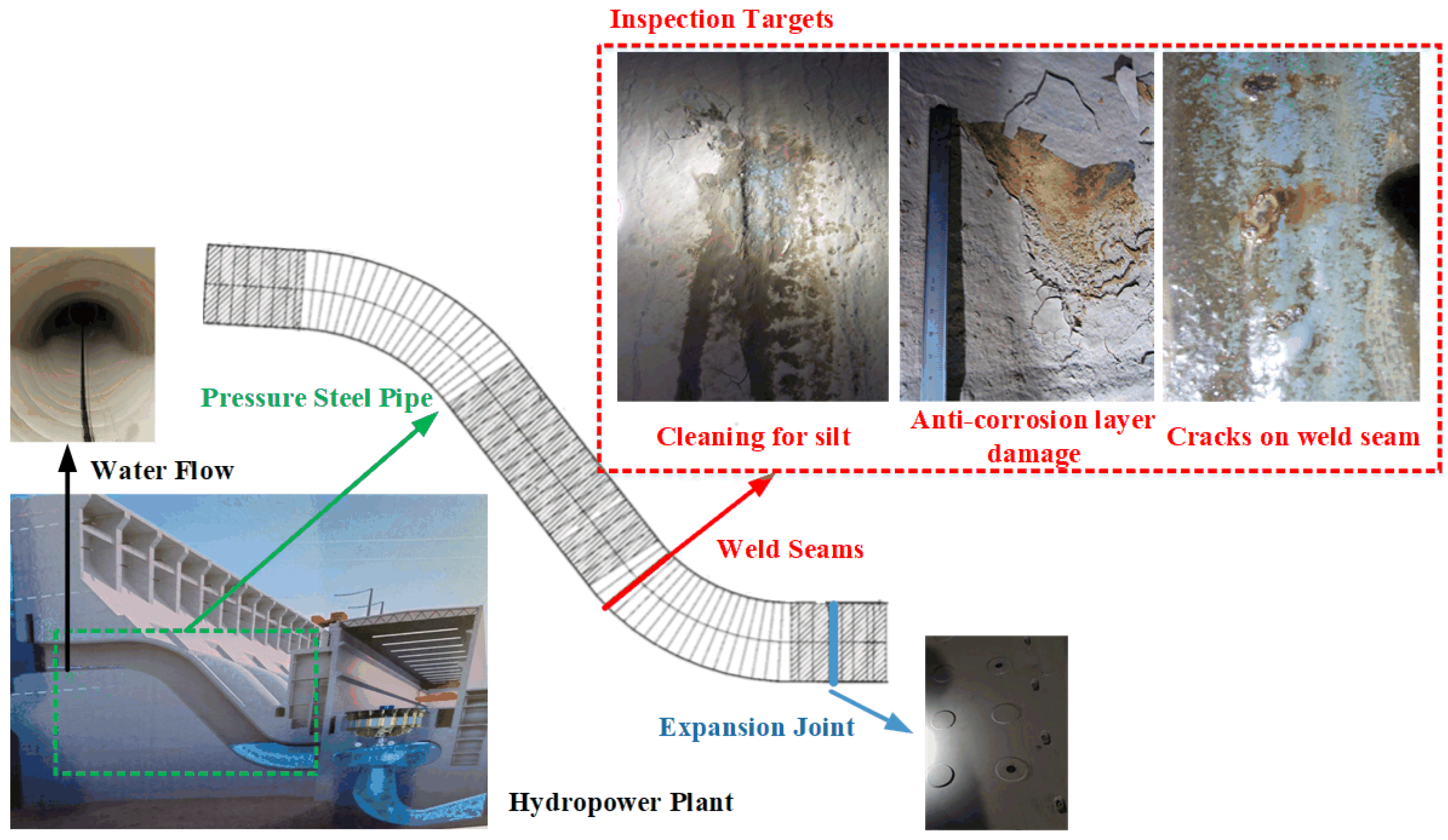
A typical pressure steel pipe consists of curved steel plates welded with each other; an example is shown in Figure 1. Thus, the types of welding seams are generally circumferential and axial. The location of the pressure steel pipe is between the inlet gate and the turbine. Caused by the water pressure change and electrolyte corrosion, the failure of pressure steel pipes mainly manifests in weld surface anti-corrosion layer damage and weld internal cracks. To detect failure, the pressure steel pipe inspection involves cleaning with high-pressure water, surface anti-corrosion layer detection, and internal flaw detection.
Figure 1. The statement of pressure steel pipe.
Two requirements need to be met for a climbing robot to be considered fit for inspections: the climbing robot with sufficient load-bearing capacity can realize reliable adsorption and flexible movement on the pipe; the accuracy of weld recognition is high enough to guide the climbing robot to finish inspections efficiently. Currently the maximum load requirement is 100 kg.
To meet the previous functional requirements while ensuring engineering feasibility, the climbing robot adopts a design which comprises a body frame with motion units. To enhance friction during climbing, tracks are selected instead of wheels as the locomotion method. To increase flexibility of movement without damaging the anti-corrosion coating on pressure steel pipes, the magnetic attraction unit employs a non-contact design. The functional equipment required for inspection tasks, such as water jet for cleaning, PAUT detector, and machine vision sensor, are mounted on the body frame and can switch between different tasks. Since cleaning agents require an external water supply, external cables are used for both power supply and communication. While this approach increases the system load to some extent, it ensures more reliable power delivery and communication.

2.2. The Mechanical Structure of Climbing Robot

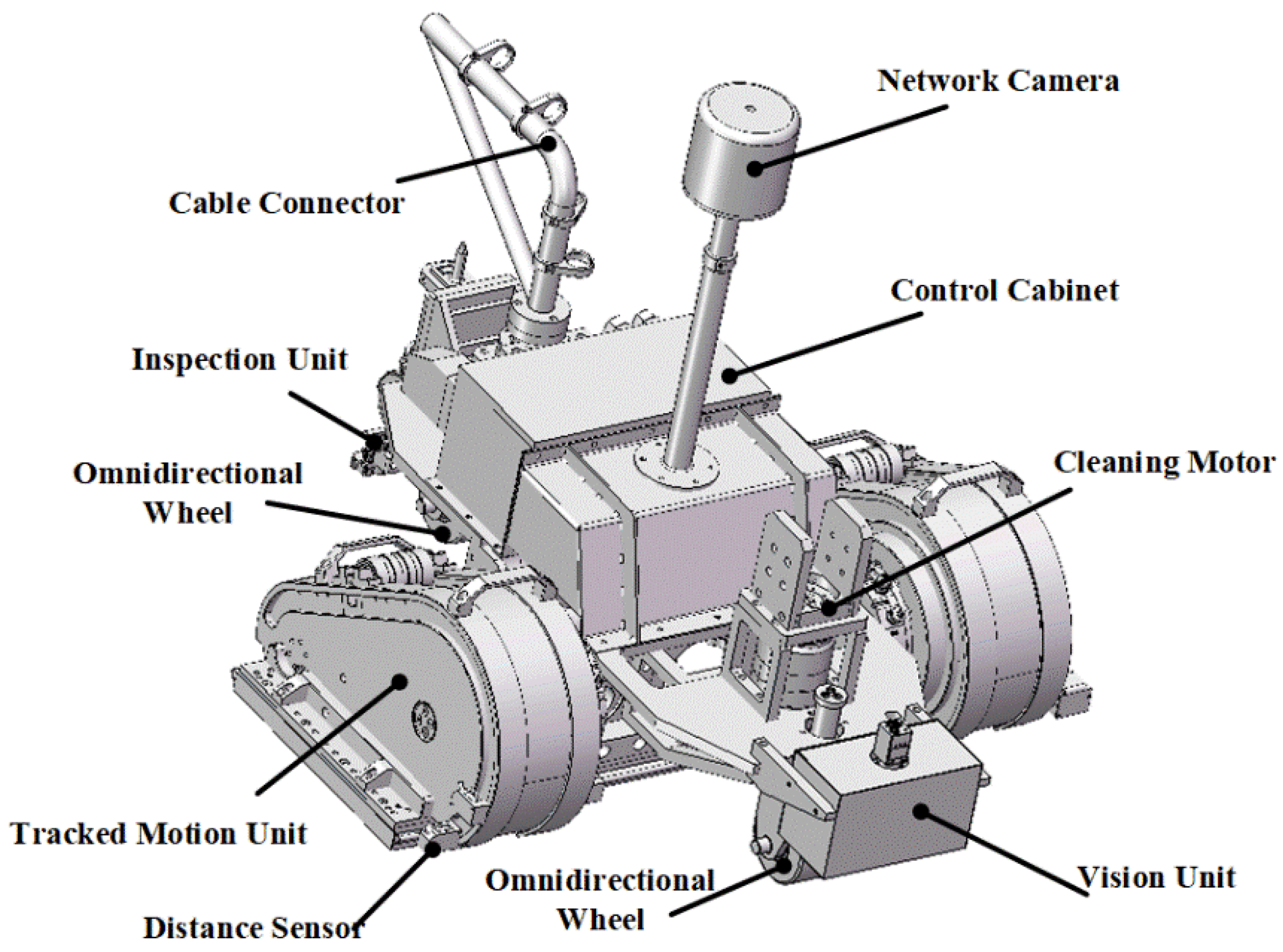
As shown in Figure 2, the climbing robot consists of the body frame, two tracked motion units, control box, and actively adjustable mechanical unit and functional units, including vision element, camera, cleaning unit, inspection units, and composite cable with power and Ethernet. Two types of magnetic adsorption units are installed on the bottom of the body frame and the side-face of the tracked motion unit. The actively adjustable mechanical unit enables simultaneous adjustment of the posture, facilitating effective adaptation to curved surfaces.
Figure 2. The structure diagram of climbing robot.
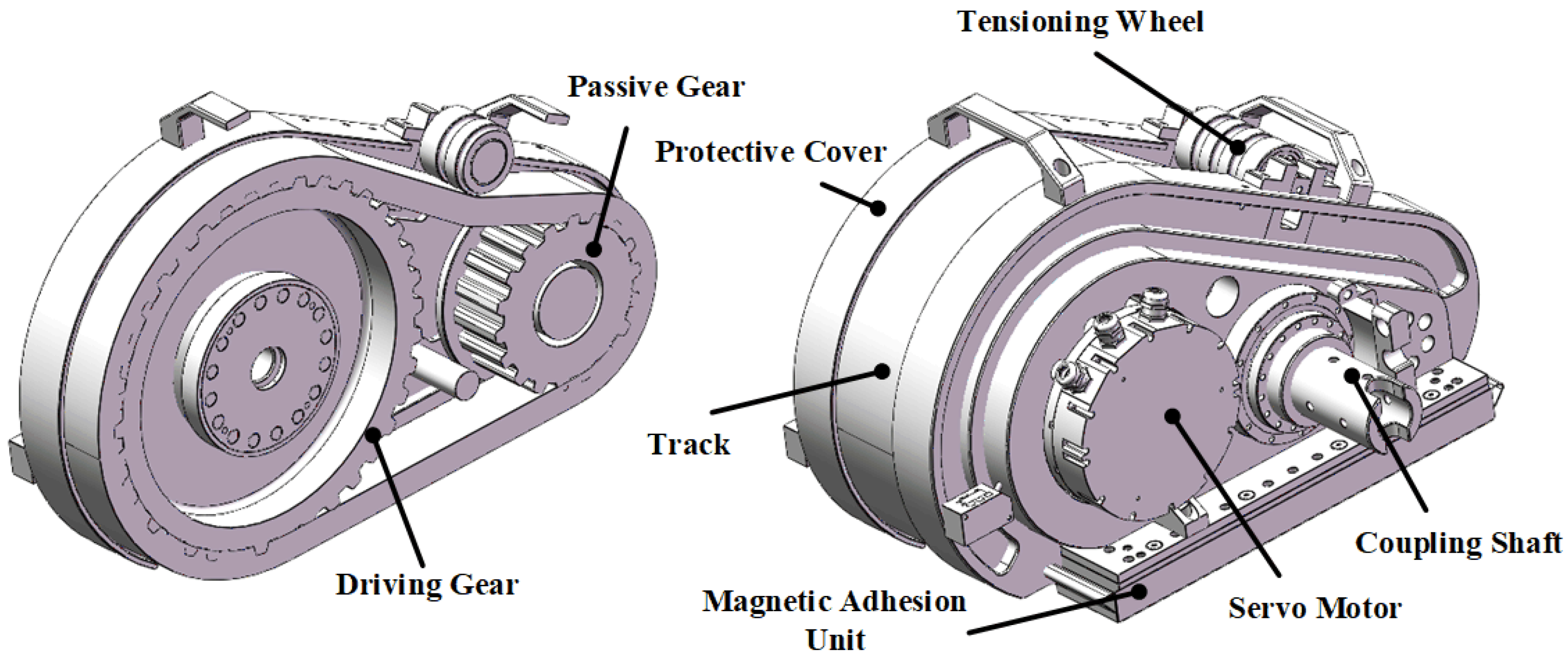
The structure of the tracked motion unit is shown in Figure 3. It consists of servo joint motor, track, pulley crawler, track shell, tensioning wheel, and bearing. The servo joint motor drives the track forward or backward via the driving gear. Independent control of the two tracked motion units enables the climbing robot to move straightly and turn around. During turns, lateral friction forces on the track pose a risk of track disengagement from the gear. Initial attempts to install guards on the gears proved ineffective; the current design employs a protective cover to prevent track slippage. The tensioning wheel primarily adjusts track tension during installation. The track motion units connect to the body frame via the connecting bearing and crankshaft. It can realize a limited range of pitch rotation with the limiting mechanism on the body frame. Each track motion unit contains a magnetic adhesion unit on both sides, along with a distance sensor to detect wall conditions and prevent falls.
Figure 3. Tracked motion unit.

2.3. The Control System of Climbing Robot

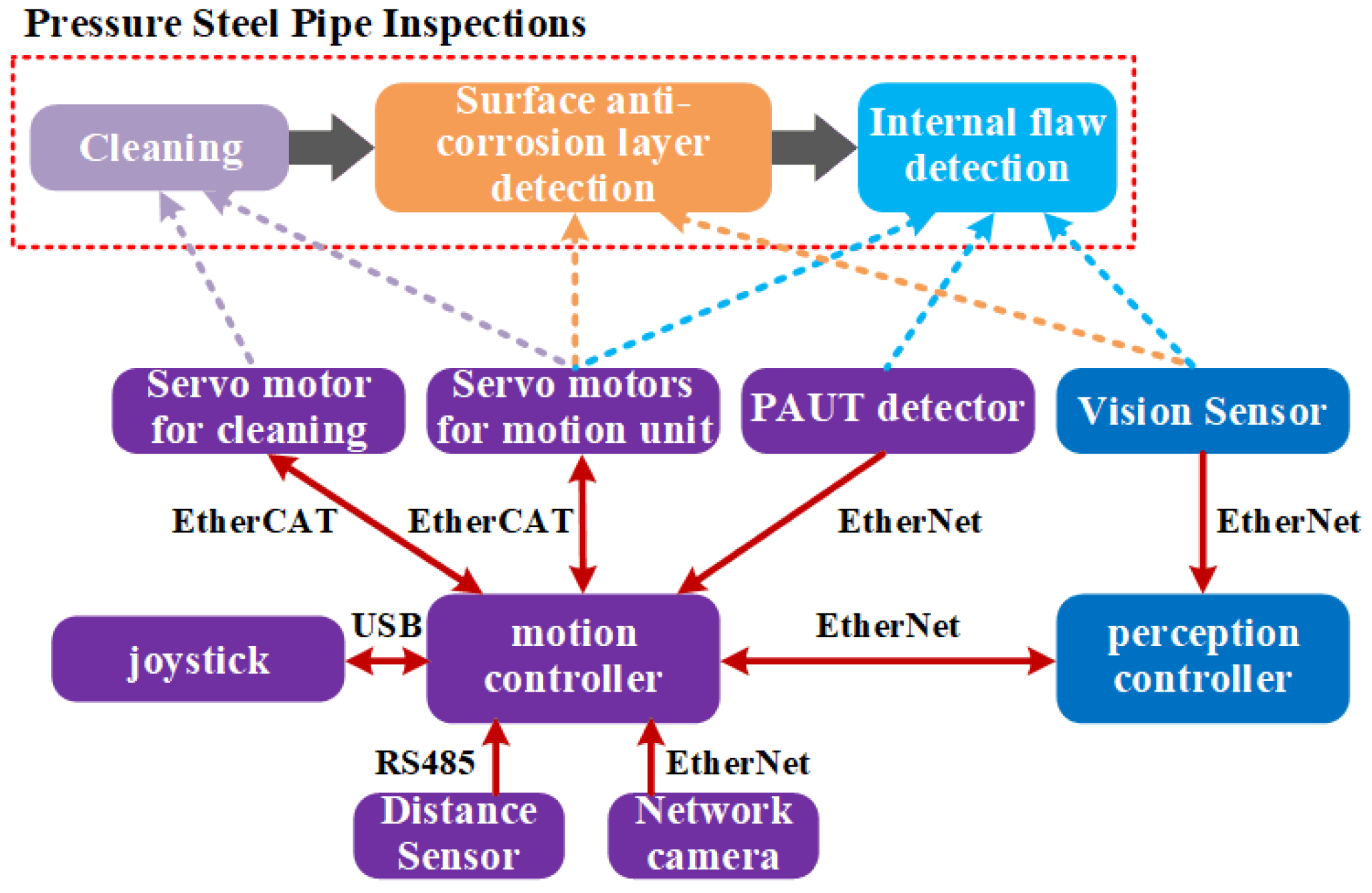
As shown in Figure 4, the control system contains a motion controller and a perception controller. To control the movements of the climbing robot, the motion controller receives commands from the operator via the joystick, processes weld seam recognition results from the perception controller, and receives position information. The perception controller focuses on collection, storage, and processing of images, and sends the weld seam recognition results to the motion controller. The perception controller and network camera communicate with the motion controller via Ethernet. The motion controller drives the climbing robot to move in the process of cleaning, surface anti-corrosion layer detection, and internal flaw detection through servo motors located in the tracked motion units. The joint servo motor is only used in the cleaning task. The vision sensor is used to capture the images of weld seams both in surface anti-corrosion layer detection and internal flaw detection. And the PAUT detector is the functional unit for internal flaw detection. To reduce the weight of the climbing robot, the motion controller is installed inside the ground-based control cabinet and communicates with the robot via Ethernet of control automation technology (EtherCAT) coupler.
Figure 4. The control system of climbing robot. Note that the solid lines indicate communication methods and the dashed line indicates certain parts at the end of the arrow are involved in the inspection task at the top of the arrow.
As shown in Figure 5, the components of the control system include motion controller, perception controller, visual sensor, distance sensor, servo motor, and network camera.
Figure 5. The component diagram of control system.
(1)
Motion controller: The model is PC6970-75 embedded controller. It is equipped with a seventh-generation Intel Core i5 processor, 4 GB of memory, and a 128 GB hard disk, running the Windows 7 system. The controller features two Ethernet cards, enabling simultaneous communication with both the EtherCAT and Ethernet.
(2)
Perception Controller: The model is the NVIDIA Jetson Xavier NX controller. It weighs 450 g. The controller is equipped with a six-core ARM architecture Carmel CPU, 8 GB of memory, and a 16 GB hard disk running the Linux operating system. It supports Ethernet and RS-442 protocols.
(3)
Vision Sensor: The model is the Hikvision MV-CA050-10GC. It has a resolution of 2448 × 2048, a pixel size of 3.45 × 3.45 μm, a frame rate of 24.1 fps, and a communication interface of GigE Vision V2.0.
(4)
Distance Sensor: The model is the Panasonic HG-C1100 laser displacement sensor. The sensor has a measurement center of 100 mm, a measurement range of ±35 mm, a repeatability accuracy of 70 μm, and a straightness of ±0.1% F.S. It can output measurement data via RS-485.
(5)
Servo Motor: To meet the waterproof and dustproof requirements during the inspections, the KGM-32CLKEC-A081 (KGM-32) and KGM-17CLKES (KGM-17) integrated rotary actuators of KaiserDrive are used. These rotary actuators integrate a servo motor, planetary reducer, encoder, and driver, with a reduction ratio of 101:1. They use a hollow shaft 19-bit multiturn absolute encoder. The tracked motion unit uses the KGM-32 rotary actuator, which has a rated speed of 25 r/min and a rated torque of 267 Nm. The track posture adjustment module and cleaning components use the KGM-17 rotary actuator, which has a rated speed of 30 rpm and a rated torque of 49 Nm, and is equipped with an electromagnetic brake to ensure the motor output shaft remains completely stationary in a disenabled state.
(6)
Network camera: The model is Hikvision DS-2DE2402IWPTZ. This camera features a built-in 2.5-inch 4-megapixel lens, capable of 2× optical zoom and 16× digital zoom. It offers 30 m infrared illumination in low-light conditions. The motion unit has a horizontal movement range of 0–360 degrees and a vertical movement range of 0–90 degrees. It can communicate via Ethernet and is suitable for low-light environments inside the pressure steel pipe.

3. Magnetic Adhesion Unit Design

Stable adhesion is a prerequisite for the climbing robot to complete inspections. Theoretically, the higher the adhesion stability, the greater the magnetic force. But this will increase the weight and size of the climbing robot. To design an effective magnetic adhesion unit, the magnetic adhesion safety analysis is proposed to find the maximum magnetic force. Since the diameter of the pressure steel pipe is much greater than the length and width of the climbing robot, the adhesion surface between the pipe and the robot is approximated as a plane. And the magnetic adhesion unit is designed based on the analysis results.

3.1. Magnetic Adhesion Safety Analysis

The unstable states of the climbing robot can be divided into sliding, detachment, longitudinal overturning, and lateral overturning.
(1)
Sliding
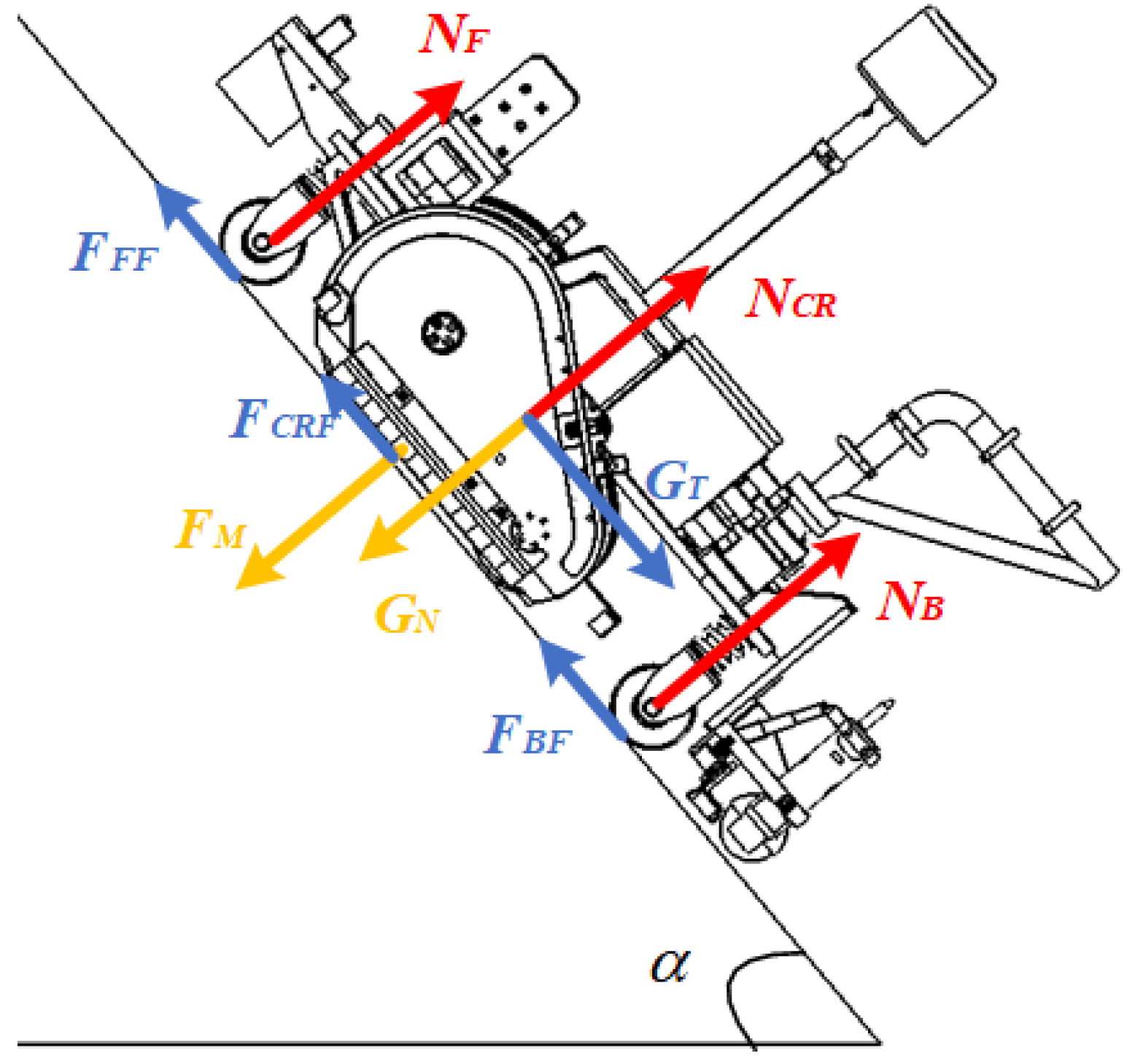
The force conditions on the climbing robot when the slipping occurs are shown in Figure 6. GN represents the normal projection of gravity. GT represents the tangential projection of gravity. FM denotes the magnetic force generated by the magnetic adhesion units. NF and NB denote the support force exerted by the surface on the omnidirectional wheels which are located at the front and rear. Assuming the track motion units on both sides of the climbing robot are in full contact with the surface and parallel to each other. The track motion unit is treated as a rigid body. NCR denotes the support force exerted by the surface on the track motion units. FFF, FBF, and FCRF represent the static friction forces between the surface and omnidirectional wheels of the tracked motion units.
Figure 6. Sliding condition.
Assuming the static friction coefficient is unchangeable, the equilibrium equations can be found as shown in Equation (1).
G N + F M = N C R + N F + N B G T F C R F + F F F + F B F F C R F + F F F + F B F = μ N C R + N F + N B
F M G N μ G T = m g sin α μ m g cos α
where m is the mass of system with the maximum 320 kg,  μ  is the friction coefficient with 0.9,  α  is the inclination angle with 0 to  2 π . When  α  is 2.32 rad, the maximum requirement of FM is 4692 N.
(2)
Detachment
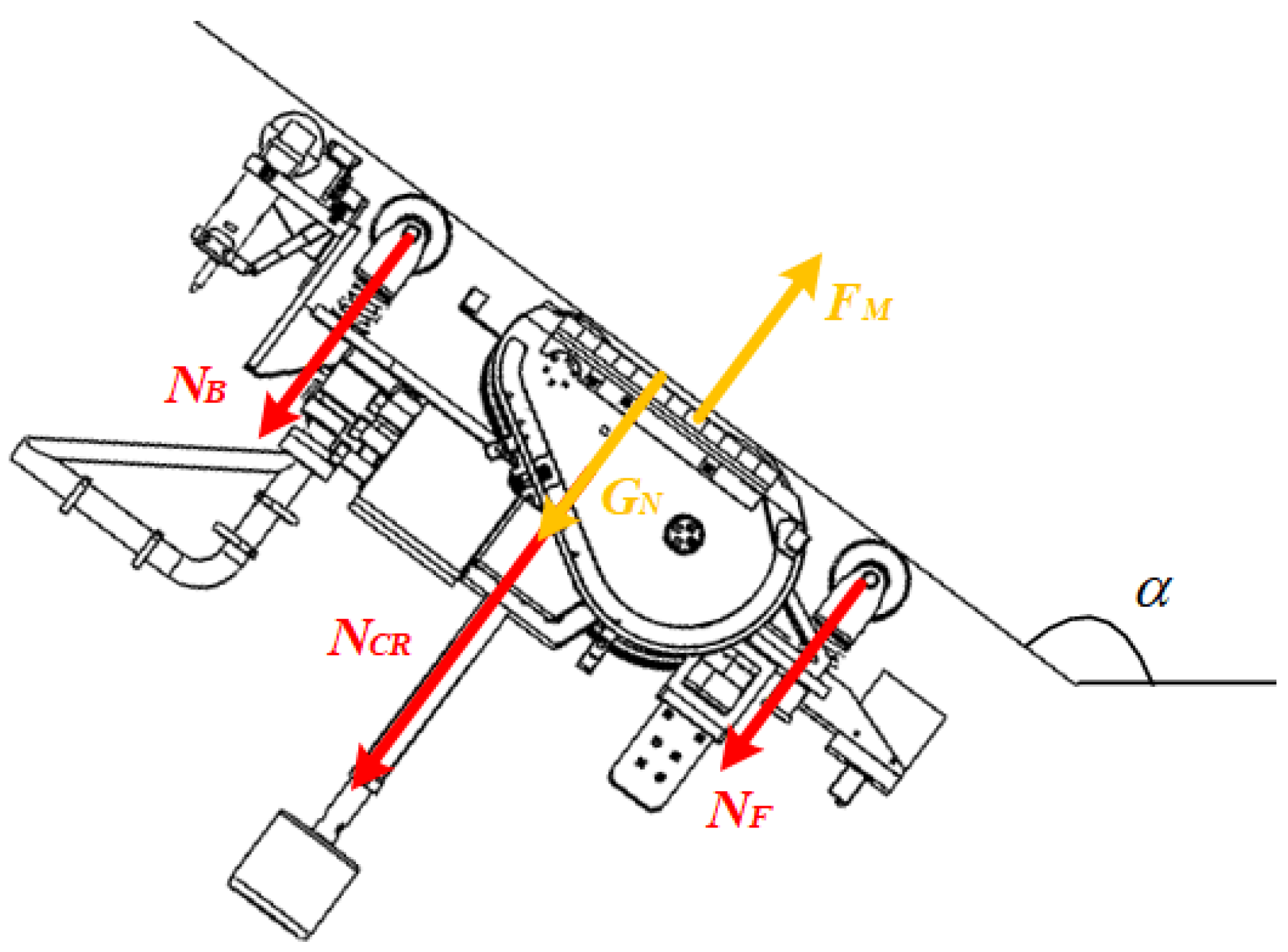
When the detachment occurs, the force conditions on the climbing robot are shown in Figure 7. As the tracked motion units and the surface are in a non-contact state, GN is equal to 0. Due to the preload caused by the spring on the omnidirectional wheels, NF and NB are equal to 50 N. Based on Equation (2), when  α  is 2.32 rad, the maximum requirement of FM is 3036 N.
F M N C R + N F + N B + G N G N = m g cos α
(3)
Longitudinal overturning
Figure 7. Detachment condition.
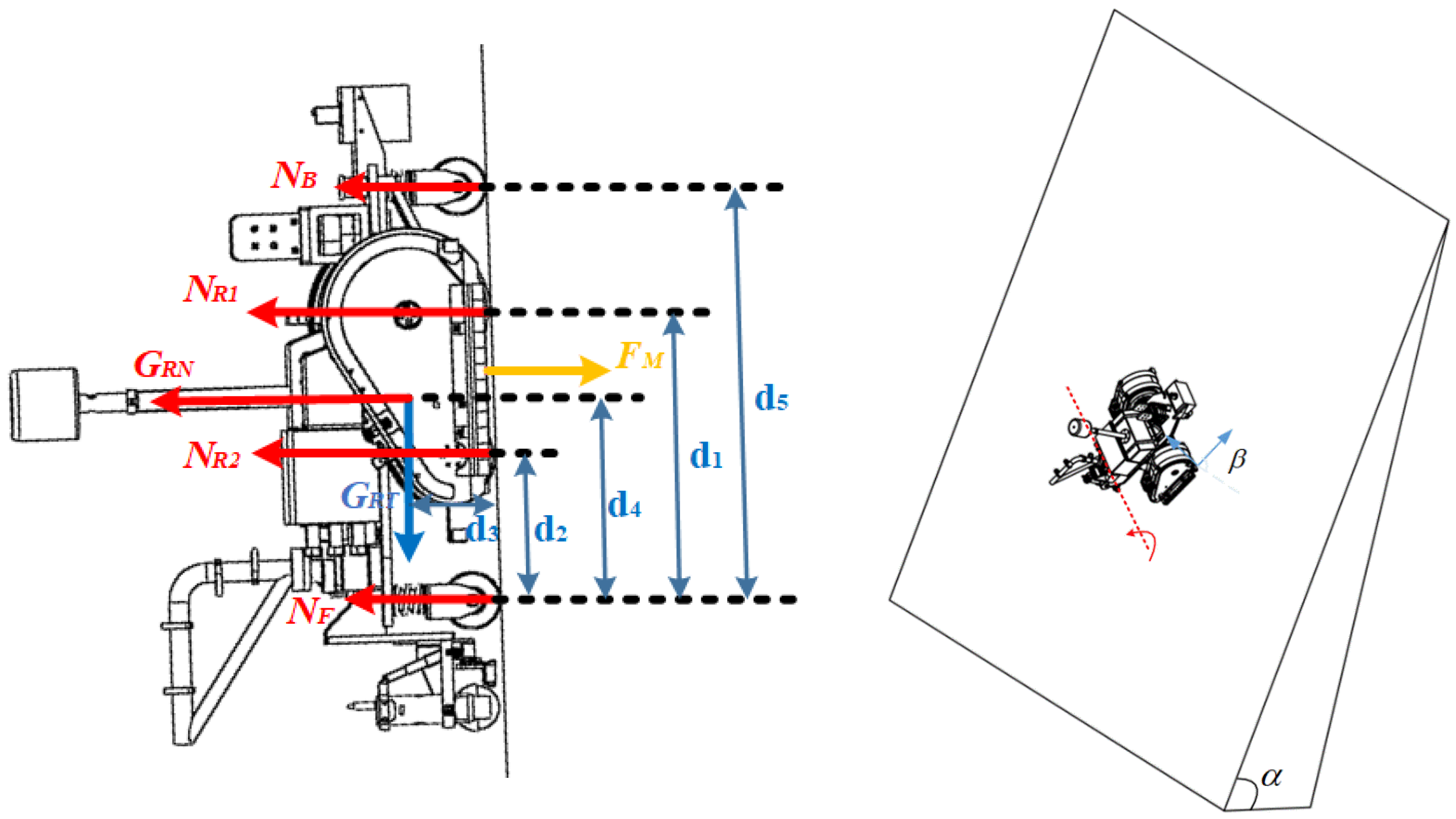
As shown in Figure 8, the climbing robot may overturn longitudinally with its rear omnidirectional wheel caused by the lack of adhesive force. GRT is the projection of gravity along the X-axis of the current climbing robot coordinate system, and GRN is the projection of Z-axis.  β  is the angle between the two X-axis of the current climbing robot coordinate and the surface coordinate. The tracked motion unit is treated as two parts: active wheel and passive wheel. NR1 denotes the support force exerted by the surface on each side of the active wheels, and NR2 denotes the support force on passive wheels. d1 is the distance from the active wheel to the rear omnidirectional wheel. d2 is the distance from the passive wheel to the rear omnidirectional wheel. d3 is the distance from the center of gravity to the surface. d4 is the distance from center of gravity to the rear omnidirectional wheel. d5 is the distance between the front and rear omnidirectional wheels. Through mechanical design, the distance from the resultant adhesive force to the rear omnidirectional wheel is  ( d 1 + d 2 ) / 2 . The force equilibrium equation and moment equilibrium equation can be expressed as
F M = N R 1 + N R 2 + N F + N B + G R N 2 N R 1 d 1 + 2 N R 2 d 2 + N F d 5 + G R T d 3 + G R N d 4 = F M d 1 + d 2 2 G R N = m g cos α G R T = m g sin α sin β
where  N R 1 = N F = 0 ,   N B = 50   N . The FM can be found in Equation (3). And the maximum is 3060 N, when  α = 2.48   rad   β   = 1.55   rad .
F M 2 ( d 4 2 d 2 ) G R N + d 3 G R T 2 d 2 N B d 1
(4)
Lateral overturning
Figure 8. Longitudinal overturning condition.
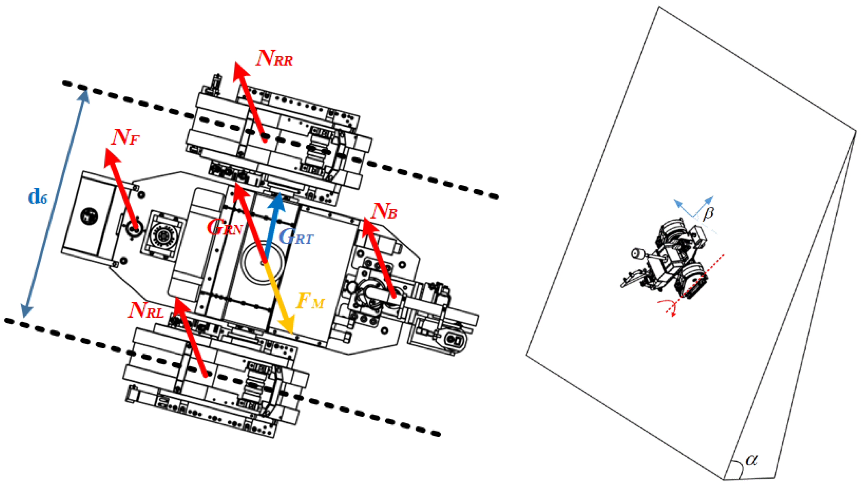
As shown in Figure 9, the climbing robot may overturn laterally when one of its tracked motion units lacks adhesive force. NRL is the support force on the left tracked motion unit, and NRR is the support force on the right one. d6 is the distance between the center of tracked motion units. The force equilibrium equation and moment equilibrium equation can be expressed as
F M + G R N = N R R + N R L + N F + N B N R R d 6 + 1 2 N F d 6 + 1 2 N B d 6 = 1 2 G R N d 6 + G R T d 3 + 2 F M d 6
where  N R R = 0 ,   N F = N B = 50   N . The FM can be found in Equation (4). And the maximum is 3560 N, when  α = 2.77   rad   β   = 0   rad .
F M N F + N B + G R Z 2 G R T d 3 d 6
Figure 9. Lateral overturning condition.
In summary, the theoretical requirement of adhesive force is 4692 N. With a safety factor equal to 2, the requirement of adhesive force is 9384 N.

3.2. Magnetic Adhesion Unit Design

The primary requirements for magnetic adhesion unit consists of three points: meeting the reliable adsorption requirements mentioned in Section 3.1, minimizing scratches on surfaces, and achieving the high ratio of adhesive force to self-weight. Thus, a non-contact permanent magnetic adhesion unit (MAU) is designed. The MAU contains multiple permanent magnets arranged in a specific sequence. Its adhesive force is determined by magnetic circuit design, dimensional parameters, magnet material, and gap spacing. In terms of magnetic circuit design, the Halbach Array [] achieves an ideal unidirectional magnetic field by arranging permanent magnets with different magnetization directions in a specific sequence, concentrating magnetic flux lines on one side of the magnet while weakening them on the other side. This is of great significance for improving ratio of adhesive force to self-weight. Based on prior research findings [], this work employs the Halbach magnetization method to design the magnetic circuit. And the finite element analysis formula for calculating the magnetic adhesion force is shown in Equation (5).
F = i = 1 N F i = i = 1 N B i 2 S i 2 μ
where Fi is the adsorption force of a single grid element; Si is the area of a single grid element; Bi is the magnetic flux intensity of each grid element; µ is the relative permeability.
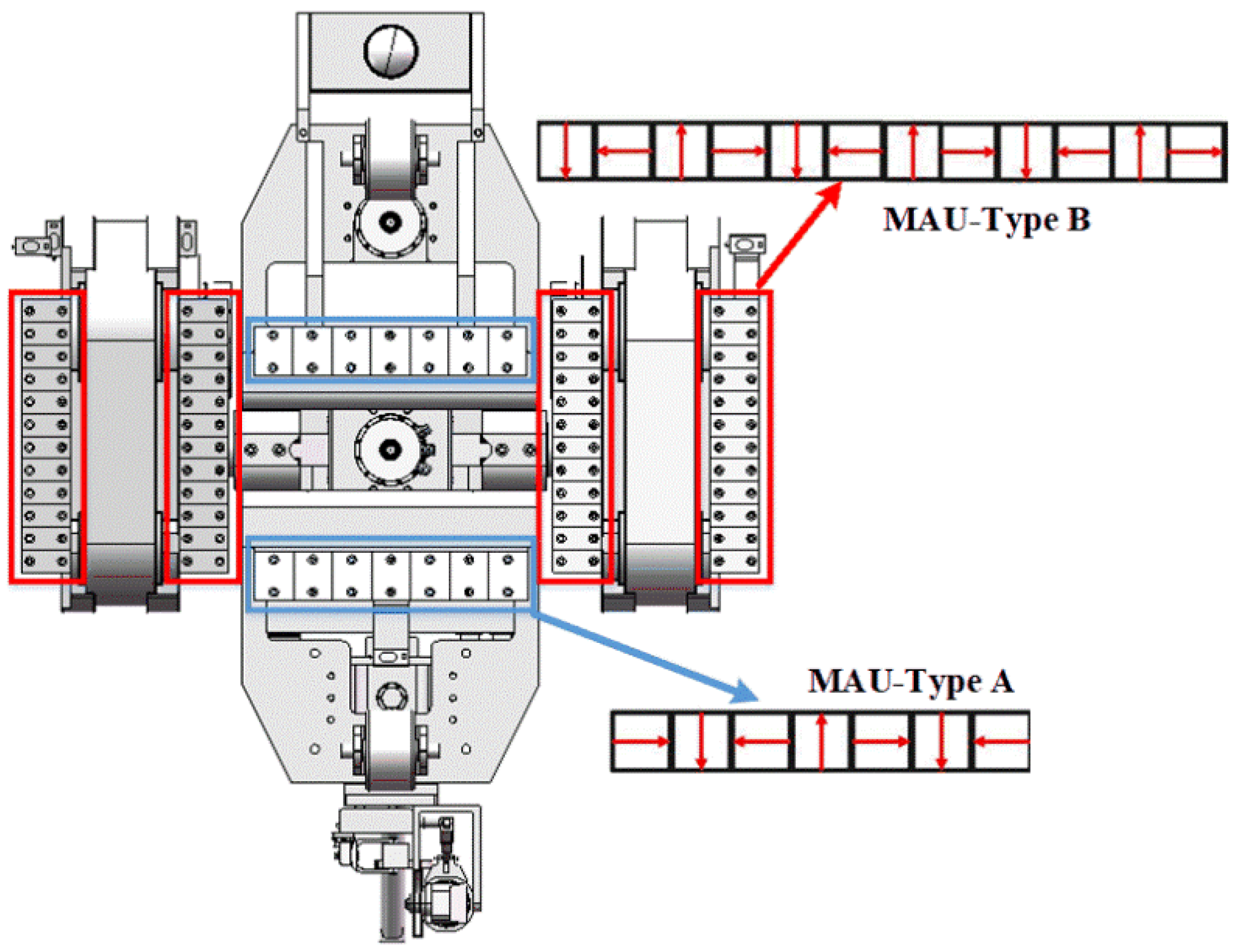
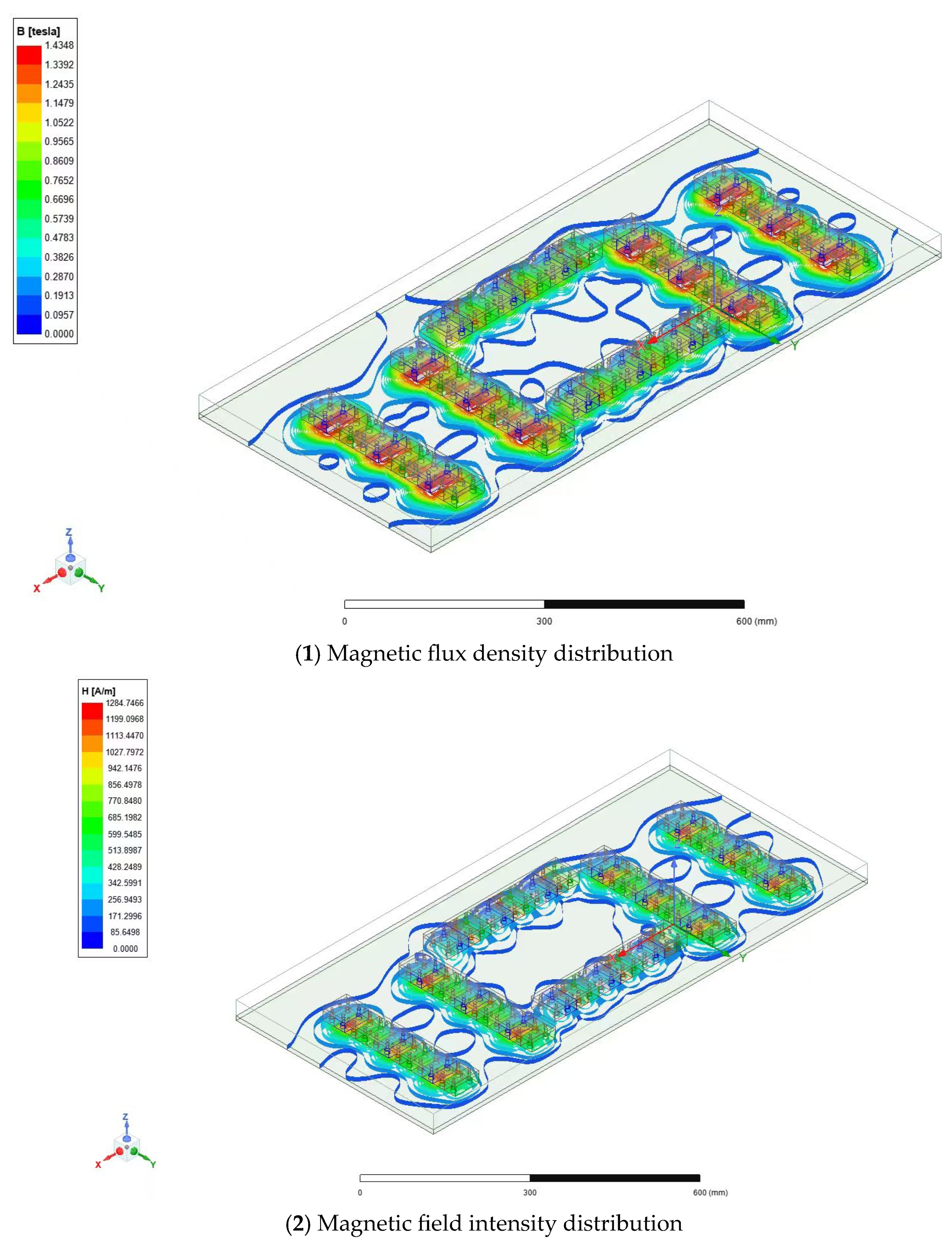
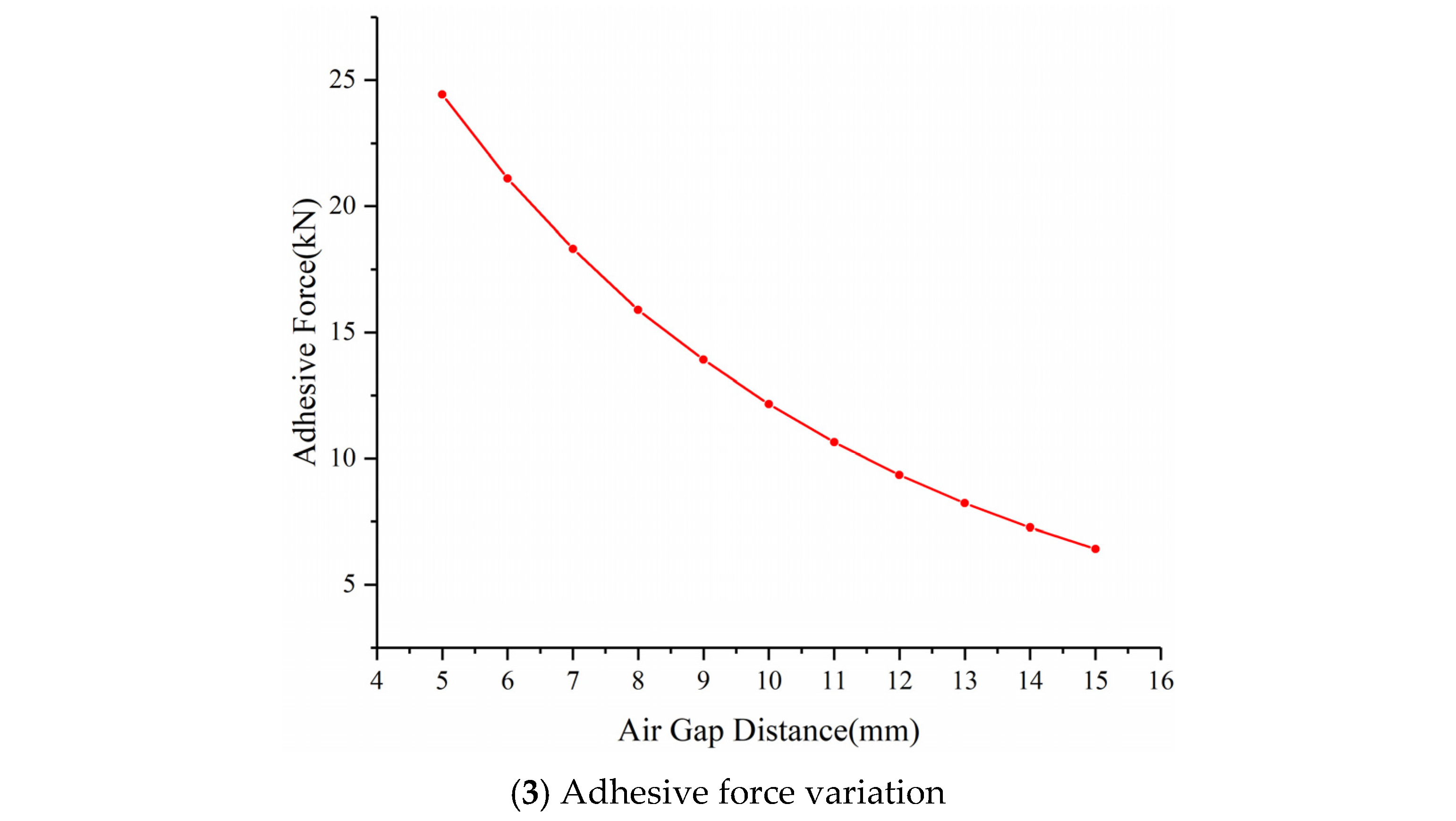
As shown in Figure 10, two types of MAUs are designed and the location of MAUs is also given. Two type A MAUs are installed at the bottom of the main frame. Four type B MAUs are installed on both sides of the tracked motion units. The planned gap is 12 mm. The permanent magnetic material used in this work is NdFeB-N35, the yoke material is pure iron, and the pressure steel pipe material selected for simulation analysis is Q235. The overall magnetic flux distribution and the variation curve of the adhesive force with respect to the gap are shown in Figure 11. Through simulation, it can be found that when the gap varies between 9 and 12 mm, the range of adhesive force variation is 13.92–9.44 KN, meeting the reliable adhesion requirements.
Figure 10. Structure of magnetic adhesion unit.
Figure 11. Adhesive analysis of magnetic adhesion unit.

4. Welding Seam Recognition

Since the inspections of pressure steel pipe primarily focus on the welded areas, the rapid and accurate weld recognition is critical in guiding the climbing robot to complete the inspections. As shown in Figure 12, the weld recognition frame is designed based on traditional image processing technology and computer vision technology. Firstly, the collected weld images are preprocessed by filtering and enhancement which removes high-frequency noise and balances image brightness to overcome the impact of uneven ambient lighting. Secondly, the preprocessed weld images are used to build a dataset for training the semantic segmentation model for weld recognition. Then the trained model is applied process actual weld seam images for the climbing robot’s trajectory guidance.
Figure 12. Welding seam recognition frame.
Based on our preliminary work [], it shows that the quality of the weld image can be improved by filtering techniques, such as mean filtering, Gaussian filtering, and edge-preserving filtering, as well as enhancement techniques, such as contrast-limited adaptive histogram equalization. However, although the brightness and contrast of the enhanced weld images are balanced, the weld features are not prominent enough. Therefore, computer vision technology is needed to improve the accuracy of weld recognition.
DeepLab is a series of semantic segmentation networks developed by Google. These networks utilize atrous convolutions to increase the receptive field and employ conditional random fields to improve the spatial consistency of segmentation. DeepLabv3 introduces a multiscale feature fusion module, which combines feature maps from different convolutional layers to achieve better segmentation performance. Additionally, DeepLabv3 employs deformable convolutions to further enhance the receptive field. DeepLabv3+ adds a decoder module to DeepLabv3 to restore the spatial resolution of segmentation results. This helps reduce jagged boundary effects in segmentation results and improves segmentation quality.
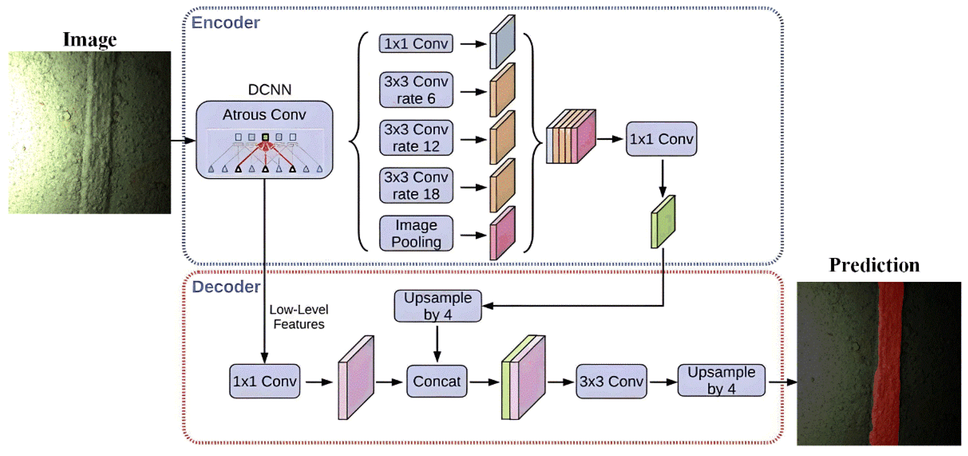
The algorithmic model of DeepLabv3+ is shown in Figure 13, which adopts the encoder–decoder structure. The encoder containing the dynamic convolution neural network component serves as the backbone network for semantic segmentation. To adapt to the processing ability of the perception controller and enhance recognition efficiency, this work replaces the classic Xception with MobileNetv2 [] as the backbone network.
Figure 13. Structure of DeepLabv3+. Note that the different colors indicate different convolutions.
MobileNetv2 is a lightweight convolutional neural network composed of two types of blocks, which are distinguished based on stride. It employs a series of lightweight design strategies, including separable convolutions, linear bottlenecks, and inverted residual structures. Feature extraction is divided into two parts: high-level semantic extraction and low-level semantic extraction. Firstly, 1 × 1 convolution kernels are used to perform sampling on the channels, serving a role similar to fully connected layers. Next, feature extraction is performed using three dilated convolution kernels. Dilated convolution increases the receptive field without adding parameters, helping to capture broader contextual information. Finally, pooling operations are performed to reduce the size of the feature maps, and the extracted feature maps are concatenated using the concatenate operation. The 1 × 1 convolution is then applied again to alter the number of channels, thereby obtaining high-level semantic information. For the low-level feature maps output by the backbone network, a 1 × 1 convolution is performed to transform the channels. The high-level feature information obtained through the above combination and channel transformation is then sampled by a factor of 4 to match the size of the low-level feature maps. The results are combined again using the concatenate operation, and the combined result is finally sampled by a factor of 4 to restore it to the input size, yielding the final output.

5. Experiments

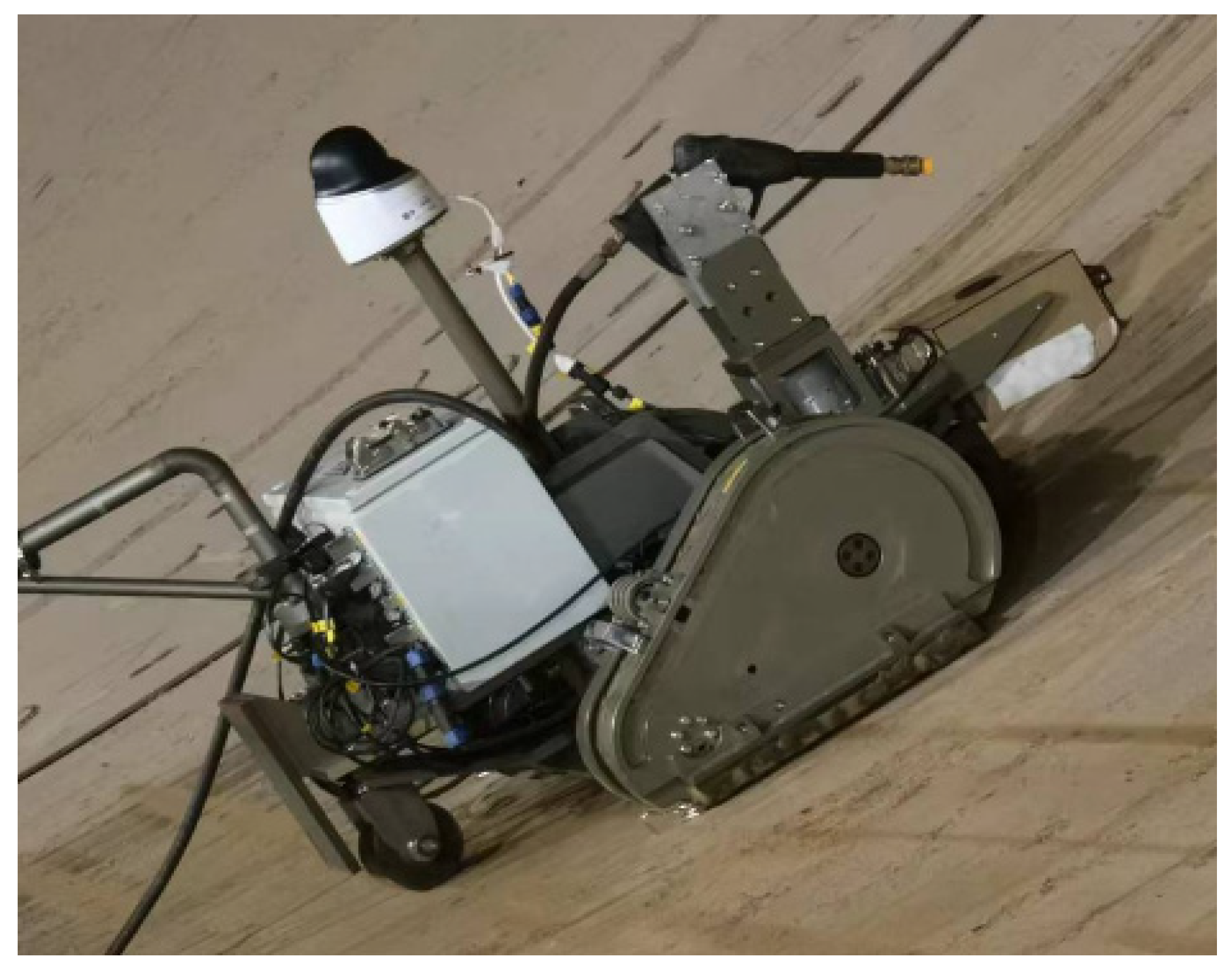
The prototype of climbing robot designed in this paper is shown in Figure 14, and its technical specifications are shown in Table 1. To verify the adsorption reliability, weld seam recognition, and ability to complete pressure steel pipe inspections, experiments were conducted inside an actual pressure steel pipe at the Three Gorges Power Plant. The size of the chosen pressure steel pipe is huge; its dimensions are as follows: 120 m of axial length, 12 m of diameter, 30 m of radius of curvature in the turning section, 54 degrees of inclination, 40–60 mm of thickness, which is also the depth of the welding seam, and 25–35 mm of welding seam width.
Figure 14. Prototype of climbing robot.
Table 1. Technical specifications of the prototype.

5.1. Adsorption Reliability and Motion Test

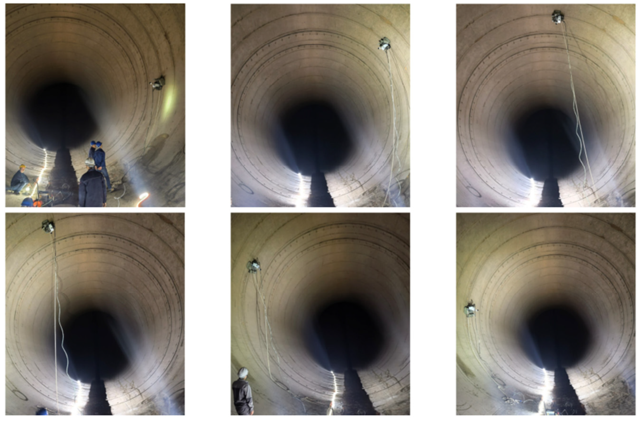
Adsorption reliability is the most important prerequisite for inspections. According to task requirements, the climbing robot is driven to perform circular movements along the circumferential welds on the inner side of the steel pipe as shown in Figure 15. According to the analysis in Section 3.2, the climbing robot is prone to slipping, longitudinal overturning, and detachment hazards at 2.32 rad, 2.48 rad, and 3.12 rad, respectively. With a load of 100 kg and without any external safety measures, the experimental results showed that the climbing robot successfully completed the circular motion without any hazardous situations occurring.
Figure 15. Adsorption reliability test.
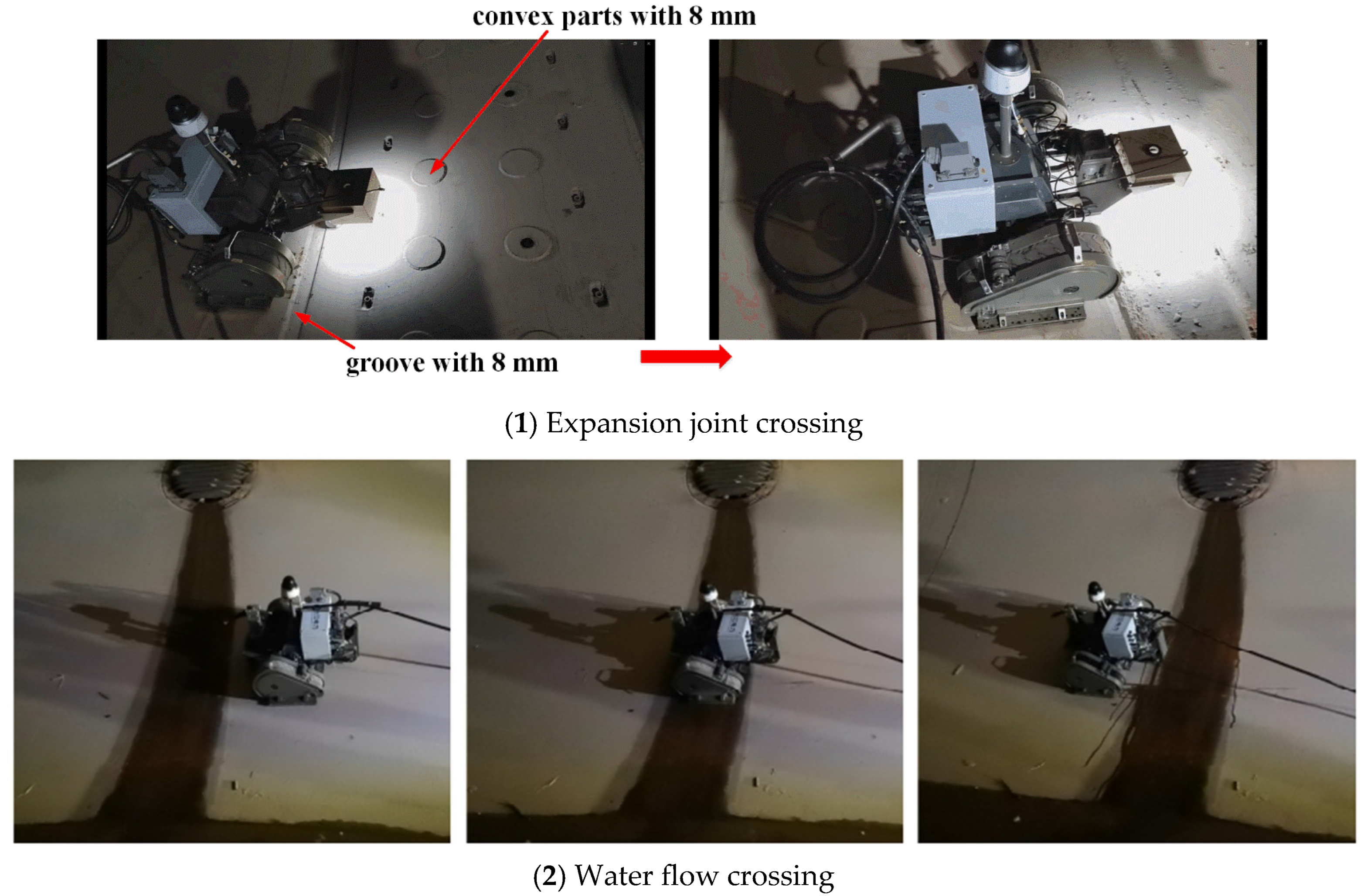
The designed weld height for pressure steel pipes does not exceed 5 mm, and the protrusions caused by damage to the corrosion-resistant coating on the weld surface also do not exceed this value. Additionally, to compensate for deformation caused by thermal expansion and contraction, pressure steel pipes are equipped with expansion joints internally. The maximum distance from the protrusions and sink points to the surface of the pipe is 8 mm. Therefore, the climbing robot must be capable of traversing expansion joints under conditions where the tracks are subjected to pressure-induced deformation. Furthermore, since there is standing water and water flow inside the pressure steel pipe, the climbing robot must have water-crossing capability to ensure a continuous inspection process. As shown in Figure 16, the climbing robot can pass through expansion joints without the chassis scraping. Additionally, the climbing robot can safely traverse water flows with a depth of 10 mm, enabling flexible movement along the inner surfaces of the pressure steel pipe.
Figure 16. Flexible movement test.

5.2. Weld Seam Recognition

In this work, weld seam images are captured by the vision sensor. From the captured images, 300 images are selected from each weld seam to construct the dataset, with a sample ratio of 9:1 between the training set and the test set. The weld seam positions are manually annotated. Data augmentation is performed on the annotated sample set using techniques such as rotation and exposure adjustment, expanding the sample size to 1500 images. The training set is input into a semantic segmentation model for training, and the model’s weight parameters are iteratively optimized.
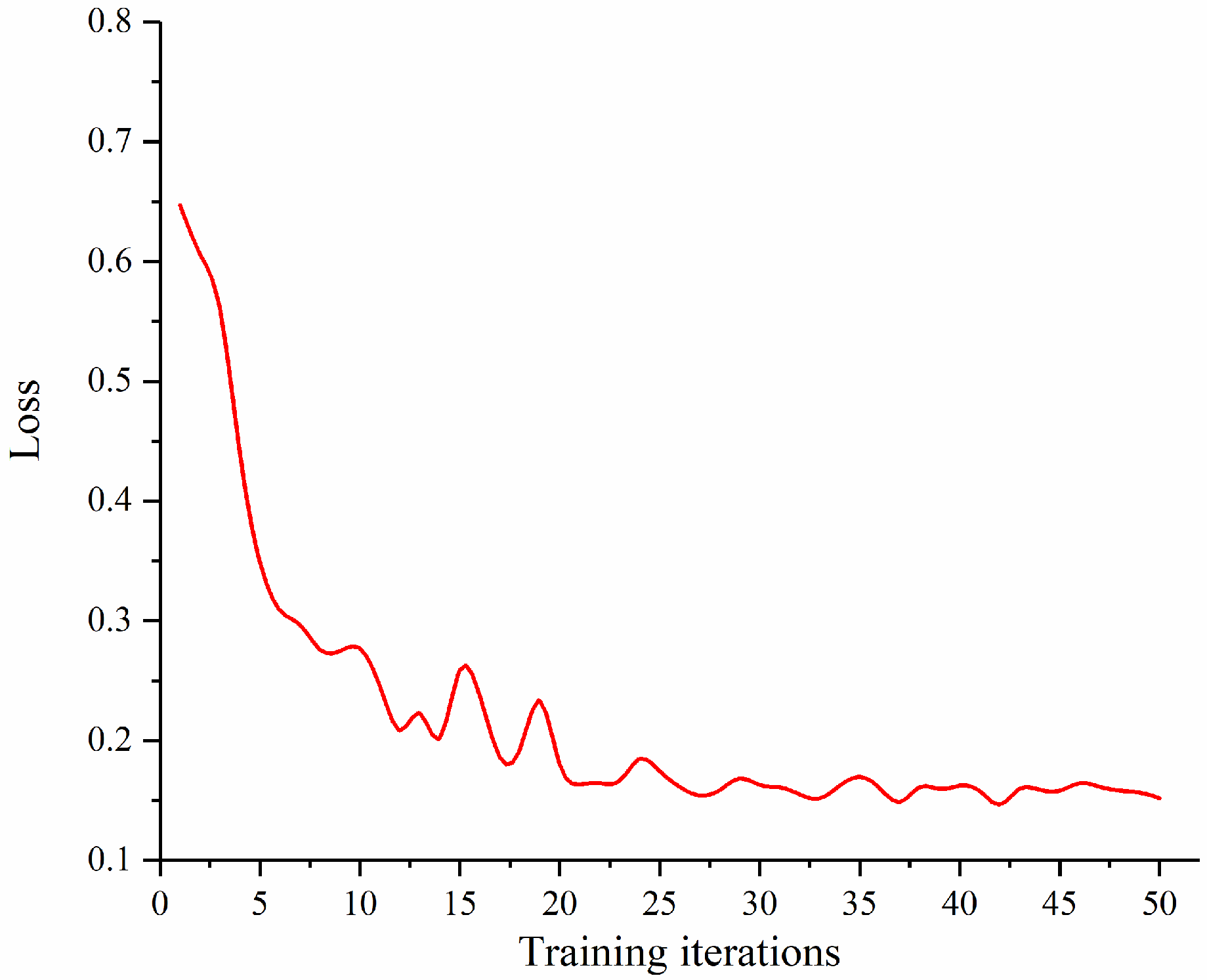
The weld seam recognition model runs on the perception controller with Ubuntu 18.04. During model training, a loss function is defined to quantify the degree of difference between the output of semantic segmentation model and the true values. The model updates its weight parameters through backpropagation to reduce the difference between the output and the true values, making the predictions more accurate. The loss function selected in this work is binary cross-entropy [], which effectively avoids gradient vanishing. The optimizer uses the adaptive moment estimation []. It calculates the first-order moment estimate and second-order moment estimate of the gradient to design independent adaptive learning rates for the parameters in the model. In this paper, the cosine annealing algorithm [] is used to dynamically update the learning rate of the optimizer. The decline process of the loss function during the training of the semantic segmentation model is shown in Figure 17. A total of 50 training iterations were performed, with the loss function value rapidly decreasing within the first 20 iterations and converging by the approximately 40th iteration.
Figure 17. Model training loss function curve.
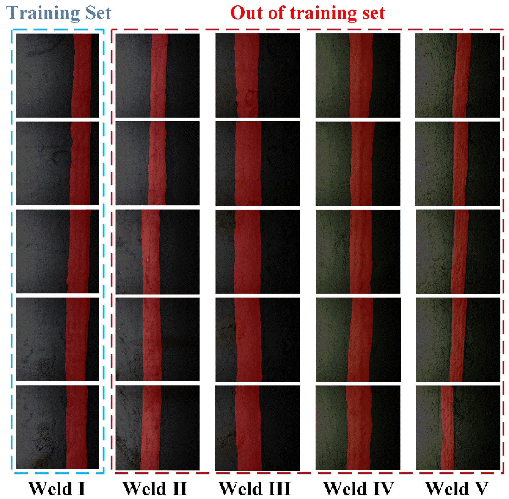
In this test, images were captured from five weld segments at different locations within the same pressure steel pipe, and the model trained in the previous section was used for weld recognition. The recognition results are shown in Figure 18. Given the wide variety of weld types, the semantic segmentation model needs to have a certain degree of generalization ability. Weld I in this test consists of images of different locations of welds in the training set, while welds II to V did not appear in the training set. The recognition results clearly show that the model has a certain degree of generalization ability and can still complete the recognition task with new welds. The mean intersection over union (mIoU) is used for evaluating the performance of semantic segmentation model. That means the ratio of the intersection to the union of the model’s predicted results for each class and their true values, summed and averaged. The formula is as follows:
m I o U = 1 N i = 1 N I o U i
where IoUi means the intersection-over-union (IoU) ratio for the i-th class label. It can be expressed as
I o U = T P T P + F P + F N
where true positive (TP) represents correctly classified positive samples, false positive (FP) represents incorrectly classified positive samples, and false negative (FN) represents incorrectly classified negative samples. The IoU for the weld seam is also presented in Table 2 as a quantitative reference for model performance.
Figure 18. Weld recognition results.
Table 2. Weld recognition test quantified results.
The IoU can be understood as the overlap between the predicted value and the true value, reflecting the accuracy of weld recognition. The actual requirement for the degree of overlap of weld recognition results should be at least 65%. The quantitative data of the segmentation model shows that the average intersection ratio of the recognition results outside the training set reached 0.8325, meaning that the degree of overlap between the recognition results and the actual image position of the welds reached more than 80%.

5.3. Pressure Steel Pipe Inspections

As shown in Figure 19, under the conditions of reliable adhesion, flexible movement, and efficient weld seam recognition, the inspection functions of the climbing robot are tested on an actual pressure steel pipe by carrying different inspection equipment (Supplementary Materials).
Figure 19. Pressure steel pipe inspections.
The pump is used to supply high-pressure water at 240 bar to clean the weld seam surface by removing surface-adhering mud and damaged anti-corrosion coatings. The on-site water flow is chosen as the working medium. By controlling the rotation angle and swing speed of the joint motor connected to the water jet and by coordinating with the climbing robot’s speed, the cleaning effect and efficiency are ensured, with a cleaning speed of 4 m2/s.
Surface anti-corrosion layer detection can be performed after the cleaning. The climbing robot is controlled to move along the weld seam. The network camera transmits images of the area near the weld seam back to the motion controller, where staff members assess the damage condition. For areas with severe surface damage, image processing is used to calculate the damaged area and record it for future reference.
Internal flaw detection is performed using a PAUT detector. The detector is mounted on the body frame of the climbing robot via a connection mechanism that securely attaches the probe. The motion controller accesses the PAUT detector via Ethernet. In accordance with the process requirements for internal flaw detection, the inspection speed is set to 1 m/s.
For the three inspection tasks, internal flaw detection requires high precision in the relative pose control between the climbing robot and the weld seam, which is also the purpose of weld seam recognition. The detection data is primarily collected and recorded by the PAUT detector. With technological advancements, the use of detectors with online identification capabilities may significantly enhance detection efficiency. In the surface anti-corrosion layer detection, the location and area of corrosion near the weld seam vary significantly, and the view field of the vision sensor cannot meet the requirements, so a network camera is used for image acquisition.
As shown in Table 3, the climbing robot for pressure steel pipe inspections possesses sufficient adhesive force to meet the high load requirements imposed by inspection equipment and long-distance composite cables. Compared with related works, the climbing robot offers higher mobility and operational capabilities, enabling efficient completion of tasks involved in inspections. It can be found that the climbing robot exhibits a lower adhesion-to-weight ratio, as contact-based adhesion generates greater magnetic force than non-contact mode. However, in tracked contact-type adhesion scenarios, non-operational magnets exist during track movement, reducing magnet utilization efficiency. Additionally, contact magnets may cause abrasion on anti-corrosion coatings during attachment and detachment. Through the motion test, the climbing robot has demonstrated the ability to achieve reliable adhesion without damaging anti-corrosion coatings.
Table 3. Comparison with related work.
There are still some issues in pressure pipe inspections that we will focus on in our subsequent research, including the positioning of the climbing robot inside pressure steel pipes, which is key to recording excessive defects and subsequent traceability; further improvement in weld recognition effectiveness and efficiency; and the design of offset strategies during internal flaw detection, mainly addressing the issue of mismatches between the climbing robot’s posture and the probe adjustment requirements. Increasing the degree of freedom of the probe position can be considered in future works to improve the probe adjustment effect.

6. Conclusions

This paper designs a multifunctional climbing robot for performing cleaning with high-pressure water, surface anti-corrosion layer detection, and internal flaw detection involved in pressure steel pipe inspections. To achieve reliable adhesion, two types of non-contact magnetic adhesion units were designed based on sliding and overturning analysis of the climbing robot. By utilizing Halbach magnetization, a high magnetic force-to-weight ratio can be achieved. To enhance weld seam recognition efficiency, an improved Deeplabv3+ semantic segmentation method was applied for weld seam recognition. The climbing robot prototype described in this paper was tested within an actual pressure steel pipe at the Three Gorges Power Plant. Experimental results demonstrate that the climbing robot possesses the required mobility and weld seam recognition capabilities, enabling it to complete pressure steel pipe inspection tasks.
At the same time, it can be found that the performance limitations still exist. Firstly, the current state of weld recognition needs to be improved. The weld seams inside pressure steel pipes are multi-layer, multi-pass welds constructed manually. This results in non-structural characteristics in weld surface width, bead distribution, and weld bead height. Combined with varying degrees of anti-corrosion coating damage caused by water erosion, the current weld recognition cannot achieve fully intelligent, unmanned motion navigation. In future work, we will focus on optimizing the visual unit’s lighting, vision sensor, and image processing methods to enhance image recognition accuracy. Additionally, integrating line laser ranging sensors to measure weld bead height for improved recognition accuracy is under consideration.
Secondly, the current climbing robot requires mounting water pipes during cleaning and uses composite cables for power and communication. The maximum equivalent load reaches 30 kg, increasing demands on the adhesion force. This necessitates larger dimensions and heavier weight, consequently reducing mobility. Given the substantial weld lengths within pressure pipes, single-operation completion is impractical. Future designs will explore swarm robotics approaches, deploying distinct robotic systems for tasks requiring water supply and composite cables versus the other tasks. For instance, surface anti-corrosion layer detection could utilize battery-powered systems to reduce weight and enhance mobility. Parallel operations can also be adopted throughout the pipeline to enhance overall inspection efficiency.
Simultaneously, to address existing defects, the current climbing robot could be further optimized by integrating articulated mechanisms and grinding/welding/coating equipment to repair these defects. This will ultimately achieve full-task operation for pressure steel pipe inspection and maintenance.
Supplementary Materials

The following supporting information can be downloaded at https://www.mdpi.com/article/10.3390/machines13100951/s1, Video S1: motion test, weld seam recognition and pressure steel pipe inspections.

Author Contributions

Conceptualization, Y.Z. and E.G.; methodology, E.G.; software, J.C.; writing—original draft preparation, E.G.; writing—review and editing, Y.W. All authors have read and agreed to the published version of the manuscript.

Funding

This research was funded by the National Natural Science Foundation of China (Grant No. 52105267).

Data Availability Statement

Data available on request due to privacy restrictions.

Acknowledgments

The authors gratefully acknowledge the experimental scene support provided by China Yangtze Power Co., Ltd. Yichang, China.

Conflicts of Interest

The authors declare no conflicts of interest.

References

  1. Tao, B.; Gong, Z.; Ding, H. Climbing robots for manufacturing. Natl. Sci. Rev. 2023, 10, nwad042. [Google Scholar] [CrossRef] [PubMed]
  2. Zhu, H.; Lu, J.; Gu, S.; Wei, S.; Guan, Y. Planning three-dimensional collision-free optimized climbing path for biped wall-climbing robots. IEEE/ASME Trans. Mechatron. 2020, 26, 2712–2723. [Google Scholar] [CrossRef]
  3. Wu, X.; Wang, C.; Hua, S. Predictor-based adaptive feedback control for a class of systems with time delay and its application to an aircraft skin inspection robot. IET Control Theory Appl. 2020, 14, 763–773. [Google Scholar] [CrossRef]
  4. Liu, Y.; Hajj, M.; Bao, Y. Review of robot-based damage assessment for offshore wind turbines. Renew. Sustain. Energy Rev. 2022, 158, 112187. [Google Scholar] [CrossRef]
  5. Bisht, R.S.; Pathak, P.M.; Panigrahi, S.K. Design and development of a glass facade cleaning robot. Mech. Mach. Theory 2022, 168, 104585. [Google Scholar] [CrossRef]
  6. Zhang, W.; Zheng, Z.; Fu, X.; Hazken, S.; Chen, H.; Zhao, M.; Ding, N. CCRobot-IV-F: A ducted-fan-driven flying-type bridge-stay-cable climbing robot. In Proceedings of the 2021 IEEE/RSJ International Conference on Intelligent Robots and Systems (IROS), Prague, Czech Republic, 27 September–1 October 2021. [Google Scholar]
  7. Huang, H.; Li, D.; Xue, Z.; Chen, X.; Liu, S.; Leng, J.; Wei, Y. Design and performance analysis of a tracked wall-climbing robot for ship inspection in shipbuilding. Ocean Eng. 2017, 131, 224–230. [Google Scholar] [CrossRef]
  8. Park, C.; Bae, J.; Ryu, S.; Lee, J.; Seo, T. R-track: Separable modular climbing robot design for wall-to-wall transition. IEEE Robot. Autom. Lett. 2020, 6, 1036–1042. [Google Scholar] [CrossRef]
  9. Nguyen, S.T.; La, H.M. Development of a steel bridge climbing robot. In Proceedings of the 2019 IEEE/RSJ International Conference on Intelligent Robots and Systems (IROS), Macau, China, 3–8 November 2019. [Google Scholar]
  10. Nguyen, S.T.; Pham, A.Q.; Motley, C.; La, H.M. A practical climbing robot for steel bridge inspection. In Proceedings of the 2020 IEEE International Conference on Robotics and Automation (ICRA), Paris, France, 31 May–31 August 2020. [Google Scholar]
  11. Adinehvand, M.; Asadi, E.; Lai, C.Y.; Khayyam, H.; Tan, K.; Hoseinnezhad, R. BogieBot: A climbing robot in cluttered confined space of bogies with ferrous metal surfaces. In Proceedings of the 2021 IEEE/RSJ International Conference on Intelligent Robots and Systems (IROS), Prague, Czech Republic, 27 September–1 October 2021. [Google Scholar]
  12. Eto, H.; Asada, H.H. Development of a wheeled wall-climbing robot with a shape-adaptive magnetic adhesion mechanism. In Proceedings of the 2020 IEEE International Conference on Robotics and Automation (ICRA), Paris, France, 31 May–31 August 2020. [Google Scholar]
  13. Kermorgant, O. A magnetic climbing robot to perform autonomous welding in the shipbuilding industry. Robot. Comput.-Integr. Manuf. 2018, 53, 178–186. [Google Scholar] [CrossRef]
  14. Seo, T.; Sitti, M. Tank-like module-based climbing robot using passive compliant joints. IEEE/ASME Trans. Mechatron. 2012, 18, 397–408. [Google Scholar] [CrossRef]
  15. Zhang, L.; Ke, W.; Ye, Q.; Jiao, J. A novel laser vision sensor for weld line detection on wall-climbing robot. Opt. Laser Technol. 2014, 60, 69–79. [Google Scholar] [CrossRef]
  16. Yadav, G.; Maheshwari, S.; Agarwal, A. Contrast limited adaptive histogram equalization based enhancement for real time video system. In Proceedings of the 2014 International Conference on Advances in Computing, Communications and Informatics (ICACCI), Delhi, India, 24–27 September 2014. [Google Scholar]
  17. Vidhya, G.R.; Ramesh, H. Effectiveness of contrast limited adaptive histogram equalization technique on multispectral satellite imagery. In Proceedings of the International Conference on Video and Image Processing, Singapore, 27–29 December 2017. [Google Scholar]
  18. Cao, Y.; Cheng, Y. SACU-Net: Shape-Aware U-Net for Biomedical Image Segmentation with Attention Mechanism and Context Extraction. IEEE Access 2025, 13, 5719–5730. [Google Scholar] [CrossRef]
  19. Badrinarayanan, V.; Kendall, A.; Cipolla, R. Segnet: A deep convolutional encoder-decoder architecture for image segmentation. IEEE Trans. Pattern Anal. Mach. Intell. 2017, 39, 2481–2495. [Google Scholar] [CrossRef] [PubMed]
  20. Lam, K.L.; Abdullah, A.; Albashish, D. Ensemble of Fully Convolutional Neural Networks with End-to-End Learning for Small Object Semantic Segmentation. In Proceedings of the 10th International Conference on Robot Intelligence Technology and Applications, Gold Coast, Australia, 7–9 December 2022. [Google Scholar]
  21. Chen, L.C.; Zhu, Y.; Papandreou, G.; Schroff, F.; Adam, H. Encoder-decoder with atrous separable convolution for semantic image segmentation. In Proceedings of the European Conference on Computer Vision (ECCV), Munich, Germany, 8–14 September 2018. [Google Scholar]
  22. Zhao, H.; Shi, J.; Qi, X.; Wang, X.; Jia, J. Pyramid scene parsing network. In Proceedings of the IEEE Conference on Computer Vision and Pattern Recognition, Honolulu, HI, USA, 21–26 July 2017. [Google Scholar]
  23. Halbach, K. Strong rare earth cobalt quadrupoles. IEEE Trans. Nucl. Sci. 1979, 26, 3882–3884. [Google Scholar] [CrossRef]
  24. Zhang, Y.; Guan, E.; Li, P.; Zhao, Y. A novel magnetic circuit design method for a permanent magnetic chuck of a wall-climbing robot. Energies 2022, 15, 6653. [Google Scholar] [CrossRef]
  25. Zhang, Y.; Guan, E.; Li, P.; Zhao, Y. An automated nondestructive testing system for the surface of pressure pipeline welds. J. Field Robot. 2023, 40, 1927–1944. [Google Scholar] [CrossRef]
  26. Sandler, M.; Howard, A.; Zhu, M.; Zhmoginov, A.; Chen, L. Mobilenetv2: Inverted residuals and linear bottlenecks. In Proceedings of the IEEE Conference on Computer Vision and Pattern Recognition, Salt Lake City, UT, USA, 18–22 June 2018. [Google Scholar]
  27. Bruch, S. An alternative cross entropy loss for learning-to-rank. In Proceedings of the Web Conference, Ljubljana, Slovenia, 19–23 April 2021. [Google Scholar]
  28. Kingma, D.P.; Ba, J. Adam: A method for stochastic optimization. arXiv 2014, arXiv:1412.6980. [Google Scholar] [CrossRef]
  29. Loshchilov, I.; Frank, H. SGDR: Stochastic gradient descent with warm restarts. arXiv 2016, arXiv:1608.03983. [Google Scholar]
Disclaimer/Publisher’s Note: The statements, opinions and data contained in all publications are solely those of the individual author(s) and contributor(s) and not of MDPI and/or the editor(s). MDPI and/or the editor(s) disclaim responsibility for any injury to people or property resulting from any ideas, methods, instructions or products referred to in the content.

Article Metrics

Citations

Article Access Statistics

Multiple requests from the same IP address are counted as one view.