Article

Comparative Study of TriVariant and Delta Three-Degree-of-Freedom Parallel Mechanisms for Aerial Manipulation

School of Mechanical and Electric Engineering, Soochow University, Suzhou 215137, China
*
Author to whom correspondence should be addressed.
Machines 2025, 13(10), 926; https://doi.org/10.3390/machines13100926
Submission received: 11 September 2025 / Revised: 26 September 2025 / Accepted: 5 October 2025 / Published: 7 October 2025

Abstract

The operational performance of robotic arms for multi-rotor flying robots (MFRs) has attracted growing attention in recent years. To explore new possibilities for aerial manipulation, this study investigates a novel parallel mechanism, the TriVariant, comprising one UP limb and two identical UPS limbs (2-UPS&UP). To evaluate its potential, we analyze its dimensional and kinematic characteristics and benchmark them against the widely adopted Delta robot, which is commonly integrated with unmanned aerial vehicles (UAVs). A prototype of the TriVariant is fabricated for experimental validation. Both analytical and experimental results reveal that, within a cylindrical task workspace characterized by a large diameter and moderate height, the TriVariant offers a more compact structure than the Delta robot, despite its slightly reduced dexterity. These findings highlight that the TriVariant is especially suitable for aerial manipulation in space-constrained environments where all limbs must be mounted beneath the UAV.

1. Introduction

Multi-rotor flying robots (MFRs), integrating unmanned aerial vehicles (UAVs) with robotic arms, possess exceptional flexibility and maneuverability. They are capable of performing tasks such as wall cleaning, power maintenance, fruit harvesting, non-destructive inspection, and crack repair in complex environments, including high altitudes and confined spaces [1,2,3,4]. By reducing labor costs and minimizing operational risks, MFRs exhibit significant potential for applications across agriculture, and industry.
In recent years, the operational performance of robotic arms for MFRs has garnered increasing research interest. Fixed or single-degree-of-freedom (1-DoF) robotic arms have been widely explored due to their structural simplicity and ease of modeling. For instance, a rigid manipulator arm [5,6] was integrated into a tilt-rotor UAV for inspection task. The 1-DoF arm presented in [7] achieves foldability and variable stiffness through an origami-inspired perpendicular folding mechanism. In [8], beyond an active rotational DoF provided by a servo motor, the manipulator incorporates a directional locking mechanism, allowing unidirectional movement of the end-effector while restricting the reverse motion, thereby mitigating impact forces during dynamic environmental interactions. However, the positioning accuracy of end effectors in fixed and 1-DoF robotic arms remains highly dependent on UAVs’ control precision, which imposes limitations on their practical applications.
Serial robotic arms are widely used in MFRs due to their structural flexibility, large workspace, and simple modeling [9]. For example, a quadrotor UAV has been equipped with a four-DoF robotic arm [10], while a hexarotor UAV integrates a six-DoF dual-arm system [11,12,13], both enabling large-amplitude movements. However, serial robotic arms still encounter challenges such as large mass, high inertia, insufficient rigidity, and low positioning accuracy. Consequently, their dynamic behavior may adversely affect the overall stability of MFRs.
Soft grippers have received considerable attention [14,15]. For instance, inspired by tendril plants and hook climbers, soft grippers driven by voltage-induced phase transitions of low-boiling-point liquids have been developed to achieve coiling deformations, eliminating the need for complex grasping strategies or high-precision positioning [16]. Similarly, drawing inspiration from octopus arms and elephant trunks, researchers have designed logarithmic spiral-shaped robots that replicate this geometric form across scales. These robots employ cable-driven actuation to enable controlled curling and uncurling motion [17]. MFRs equipped with soft grippers are capable of adaptively grasping objects of various shapes and sizes in unstructured environments. However, improving the positioning accuracy of soft grippers remains a key challenge.
Parallel manipulators, known for their high precision, stiffness, and speed, have been employed in MFRs to enhance positioning accuracy [18,19]. Most existing studies [20,21,22,23] utilize Delta robots [24,25,26,27] mounted beneath UAVs to perform tasks such as data acquisition, sample collection, and 3D printing. Other works [28,29,30,31] place Delta robots laterally on UAVs to enable interactions with vertical surfaces. In these configurations, UAVs are responsible for coarse positioning across large spatial areas, enabling fast global navigation and broad adjustments, while Delta robots execute fine positioning for high-precision operations within localized regions. However, the considerable number of links in the Delta robot may hinder its dexterous performance and pose challenges for accurate dynamic modeling. In addition to Delta robots, a six-DoF parallel manipulator with a 6-RUU configuration, comprising six legs, each with a driven revolute joint and two universal joints, has been developed and mounted directly on a UAV. However, its structural rigidity and load-bearing capacity remain insufficient for carrying grippers and performing physically interactive tasks [32]. Moreover, a 6-DoF hybrid cable-driven parallel manipulator featuring a central elastic rod has been integrated with a UAV for contact-based inspection of floating offshore wind turbines. Despite its compact design, this system currently lacks the ability to exert adequate force on the environment during operation [33].
Although the Delta robot remains mainstream in aerial manipulation, it raises a key question: is there a parallel mechanism that is both compatible with the Delta robot and suitable for aerial applications? In this paper, we turn our attention to the TriVariant [34,35,36,37] composed of one UP limb, two identical UPS limbs (2-UPS&UP), and a 2-DoF head on the moving platform. For simplicity, we use the term “TriVariant” to denote the 2-UPS&UP parallel mechanism. Similar to the Delta robot, the TriVariant features high dynamic performance, structural rigidity, and a favorable cylindrical workspace-to-footprint ratio. It has been successfully applied in high-speed machining tasks such as milling, drilling, deburring, welding, and assembly within the aerospace and automotive industries. To evaluate its suitability for aerial manipulation, this study conducts a comparative analysis of the TriVariant and Delta robot in terms of dimensional characteristics and kinematic performance. Additionally, a TriVariant prototype is fabricated for trajectory tracking evaluation and integrated with a UAV platform to validate its capabilities in aerial manipulation tasks.
The remainder of this paper is organized as follows. Section 2 details the forward and inverse kinematics of the TriVariant. Section 3 presents the forward and inverse kinematics of the Delta robot. Section 4 provides a comparative analysis of the two mechanisms in terms of dimensional characteristics and kinematic performance. Section 5 describes the trajectory tracking experiments of the TriVariant and its integration with a UAV platform for aerial manipulation. Section 6 provides a detailed discussion of this work, and Section 7 concludes the paper.

2. Kinematics of the TriVariant

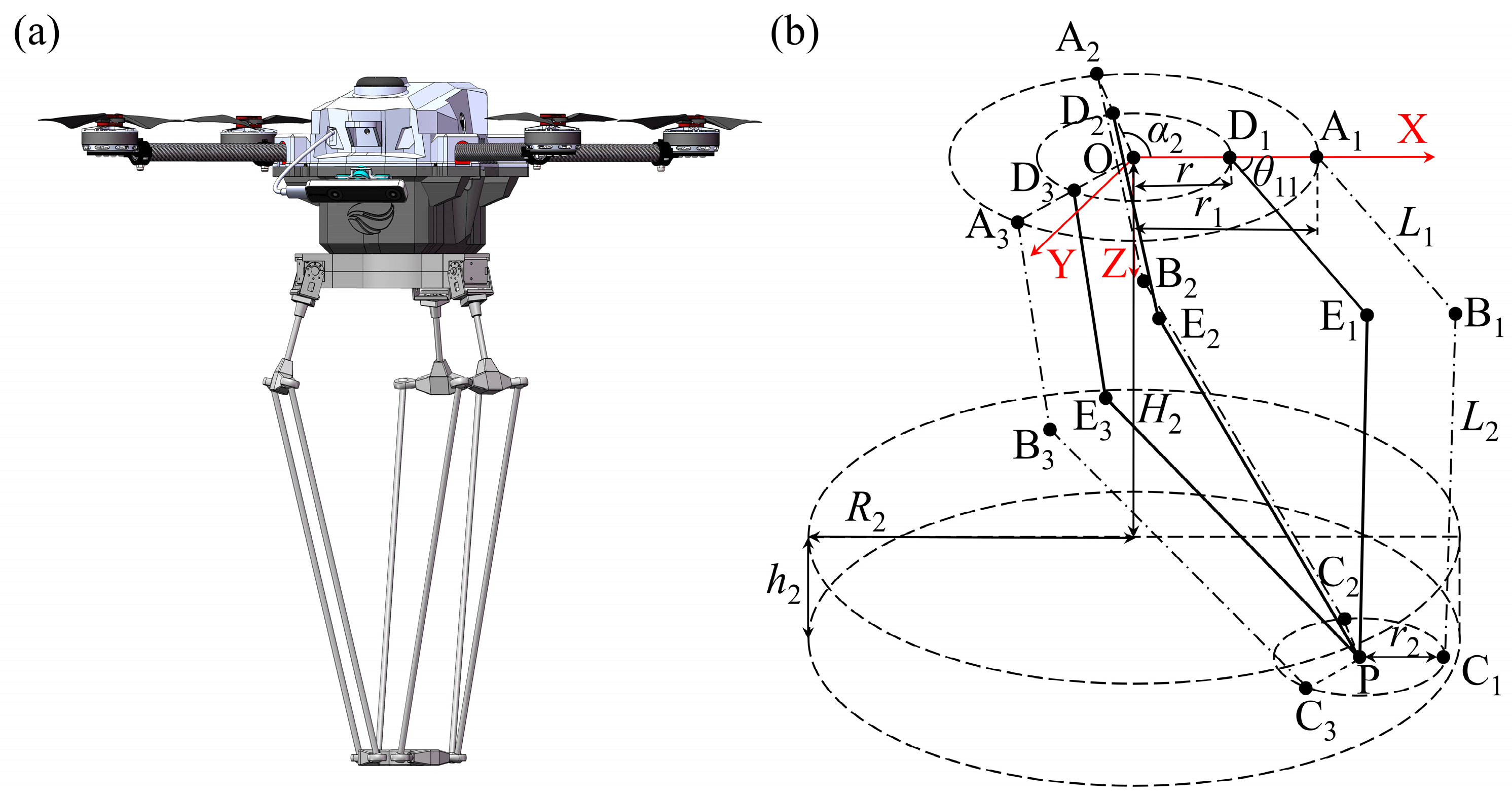
In this paper, we aim to develop a MFR by integrating the TriVariant with a UAV, as shown in Figure 1a. The kinematic structure of the TriVariant is illustrated in Figure 1b. The moving platform and the fixed base are denoted by equilateral triangles A1A2A3 and B1B2B3, with side lengths of a and b, respectively. The i-th limb (i = 1, and 2) is a UPS limb, connecting the fixed base via a U joint and the moving platform via an S joint. The third limb is a UP limb, connecting the fixed base with a U joint at one end and perpendicularly fixing to the moving platform at the other. All rotational axes of the three U joints lie within the B1B2B3 plane. A local Cartesian coordinate frame, Bj-xjyjzj (j = 1, 2, and 3), is set up at the base where the origin of the frame is coincident with the point Bj; the xj-axis lies within the B1B2B3 plane and is perpendicular to the line segment B1B2; the zj-axis is normal to the B1B2B3 plane; and the yj-axis follows the right-hand rule. The designed task workspace of the TriVariant, denoted by Wt, is cylindrical with a relatively large radius R1 and moderate height h1. Further, to achieve axisymmetric kinematic performance relative to the x3-z3 plane within Wt, a global Cartesian coordinate frame, O-XYZ, is defined. the X-axis is collinear with the x3-axis; the Y-axis lies within the B1B2B3 plane and is parallel to the y3-axis; the Z-axis aligns with the central axis of Wt; and the origin O is offset from the point B3 with a distance of e. The vertical distance from the base to the upper boundary of Wt is denoted by H1.

2.1. Forward Kinematics

The positions of points A1, A2 and A3 are denoted by
A 1 = x 1 y 1 z 1 T
A 2 = x 2 y 2 z 2 T
A 3 = x 3 y 3 z 3 T
According to the structure of the TriVariant, eight geometric constraints are obtained:
A 1 A 2 = A 1 A 3 = A 2 A 3 = a
A i B i = q i       i = 1 , 2 , 3
where qi is the length of the axial axis of the i-th limb (i = 1,2, and 3).
A 3 B 3 A 1 A 3
A 3 B 3 A 2 A 3
It can be observed that the number of unknown parameters for points A1, A2 and A3exceeds the number of geometric constraints by one. As a result, given the lengths of the three limbs qi, the solutions for A1, A2 and A3 is not unique. For more details, please refer to [37].

2.2. Inverse Kinematics

The vector of B3A3 is given by
r 3 = q 3 w 3
r 3 = b i + q i w i a i ,   i = 1 , 2
where wi is the unit vector of the axial axis of the i-th limb; a1, a2, b1, and b2 are the vectors of A3A1, A3A2, B3B1, B3B2, respectively.
The norms of Equations (8) and (9) are given by
q 3 = r 3
q i = r 3 + a i b i ,   i = 1 , 2

2.3. Jacobian Matrix

Rewriting Equations (8) and (9), it yields
w 3 = r 3 q 3
w i = r 3 + a i b i q i , i = 1 , 2
The velocity mapping function of the TriVariant is given by [35]
r ˙ 3 = J q ˙
where   q ˙ is the velocity of three prismatic joints of three limbs; r ˙ is the velocity of A3; J is the Jacobian matrix, and
q ˙ = [ q ˙ 1   q ˙ 2     q ˙ 3 ] T
J = ( [ w 1     w 2     w 3 ] T 1 q 3 [ w 1 T w 3 a 1     w 2 T w 3 a 2     0 ] T ) 1

3. Kinematics of the Delta Robot

The Delta robot is composed of a fixed base, a moving platform, and multiple identical limbs, each consisting of an upper arm and a forearm. As shown in Figure 2a, the upper arm is connected to the fixed base and the forearm via revolute joints. The forearm forms a parallelogram structure, with its four links connected by spherical joints. One of the forearm links is either rigidly attached to the moving platform or connected to it through a revolute joint.
Figure 2b illustrates the schematic diagram of the Delta robot. The fixed base and the moving platform are denoted by circles A1A2A3 and C1C2C3 centered at O and P, respectively, with radii r1 and r2. The upper arms are denoted by AiBi with a length of L1, and the forearms are denoted by BiCi with a length of L2. To simplify the model, each limb is translated by a distance of r2 along the direction of CiP. Such that, Ai is shifted to Di; Bi to Ei, and Ci coincides with P. Consequently, the radius of the new circle D1D2D3 is given by r = r1r2.

3.1. Forward Kinematics

A global Cartesian coordinate frame O-XYZ is set up with its origin at O; the X-axis aligns with OA1; the Z-axis is normal to the A1A2A3 plane; and the Y-axis is determined by the right-hand rule. The vector of point P is denoted by
p = X P Y P Z P T
According to the structure of the Delta robot, three geometric constraints are obtained:
c i = L 2 , i = 1 , 2 , 3
where ci is the vector of EiP. As the number of unknown parameters of point P is equal to the number of geometric constraints, the position of point P can be calculated, and the workspace of the Delta robot is obtained.

3.2. Inverse Kinematics

The angle between ODi and the X-axis is denoted by αi. The angle between ODi and DiEi, is denoted by θ1i. The vector of the point Ei is expressed as
e i = ( X E i , Y E i , Z E i ) T = a i + b i = R i 0 r 0 0 + L 1 cos θ 1 i 0 sin θ 1 i ,   i = 1 , 2 , 3
where ai and bi are the vectors of ODi and DiEi, respectively, and 0Ri is a rotation matrix:
R i 0 = cos α i sin α i 0 sin α i cos α i 0 0 0 1
The length of EiP is calculated by
X E i X P 2 + Y E i Y P 2 + Z E i Z P 2 = L 2 2
Rewriting Equation (18), it yields
M 1 i cos θ 1 i + M 2 i sin θ 1 i = M 3 i
where
M 1 i = 2 L 1 r 2 L 1 cos α i X P 2 L 1 sin α i Y P M 2 i = 2 L 1 Z P M 3 i = L 2 2 L 1 2 X P r cos α i 2 Y P r sin α i 2 Z P 2
Equation (19) is solvable if and only if
M 1 i 2 + M 2 i 2 M 3 i 2

3.3. Jacobian Matrix

According to the structure of the Delta robot shown in Figure 2b, we have
p = a i + b i + c i
Differentiating Equation (21), it yields
p ˙ = a ˙ i + b ˙ i + c ˙ i = ω b i × b i + ω c i × c i
where ωbi and ωci are the angular velocities of bi and ci, respectively. Multiplying both sides of Equation (22) by a unit vector c ^ i, it yields
c i p ˙ = c i ( ω b i × b i ) = ( b i × c i ) ω b i = ( b i × c i ) ω ^ b i θ 1 i
where ω ^ bi is the unit vector of ωbi.
ω ^ b i = R i 0 0 1 0 T = sin α i       cos α i       0 T
Equation (23) can be rewritten as
J p p ˙ = J θ θ ˙
where
J p = c 1 c 2 c 3 T
J θ = ( b 1 × c 1 ) ω ^ b 1 0 0 0 ( b 2 × c 2 ) ω ^ b 2 0 0 0 ( b 3 × c 3 ) ω ^ b 3
Equation (25) can be further rewritten as follows
p ˙ = J θ ˙
where J is the Jacobian matrix, and
J = J p 1 J θ

4. Performance Comparison of the TriVariant and the Delta Robot

4.1. Dimension

To compare the performance of the TriVariant and Delta robot, their design parameters must first be defined. Three key considerations are taken into account during this process. First, both robots are required to operate within an identical cylindrical task workspace, characterized by a relatively large diameter and moderate height. Second, the diameter of their moving platforms must be identical to ensure a fair comparison. Finally, the design parameters of both robots are optimized to ensure they operate in their best configurations for achieving the designed workspace prior to performance evaluation.
It is worth noting that different optimization approaches, such as the minimum dimension criterion [26] and motion/force transmission indices [27], can significantly affect the selection of design parameters. To ensure generality and fairness, the design parameters of the Delta robot are determined by scaling down one of the most widely adopted industrial models, the ABB IRB 360-1/800. In contrast, the design parameters of the TriVariant robot are based on the optimized results presented in [35], with their relationships defined in Equation (27). A summary of the design parameters used for comparison is provided in Table 1.
R 1 = R 2 ,   h 1 = h 2 a = 3 r 2 ,   b = R 1 / 1.455 ,   e = 0.782 b q 3 min = H 1 ,   q 3 max = ( R 1 + e ) + ( H 1 + h 1 ) q i max q i min q i min 0.75 , i = 1 , 2 , 3
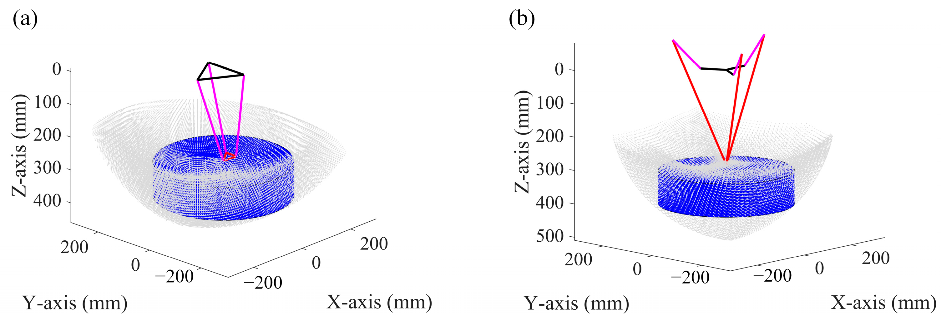
Based on the design parameters listed in Table 1, the reachable workspace of the TriVariant is illustrated as grey dots in Figure 3a, encompassing the designed cylindrical workspace with a radius of 200 mm and a height of 100 mm, highlighted in blue. Similarly, the reachable workspace of the Delta robot is shown in Figure 3b with the same designed workspace indicated. These results confirm that both robots achieve identical task workspaces under the given design parameters. Notably, the TriVariant features a smaller base radius and a shorter vertical distance from its base to the workspace compared to the Delta robot. Moreover, all three limbs of the TriVariant are located beneath its base, whereas the upper arms of the Delta robot may extend above its base. These structural characteristics indicate that the TriVariant exhibits a more compact structure compared to the Delta robot.

4.2. Dexterity

The condition number k of the Jacobian matrix is one of the most suitable local performance measures for evaluating the dexterity between the joint variables and the reference point of the moving platform [38]. To compare the kinematic performance of the TriVariant with the Delta robot, the condition number of the Jacobian of both robots is evaluated throughout the designed workspace Wt using the design parameters given in Table 1.
κ J = J J 1
Since k varies with changes in configuration of the system, two global conditioning indices, the mean value k ¯ and standard deviation k ~ of k in the designed workspace Wt, are also used as performance indices.
κ ¯ = W t κ d W t W t
κ ˜ = W t ( κ κ ¯ ) 2 d W t W t
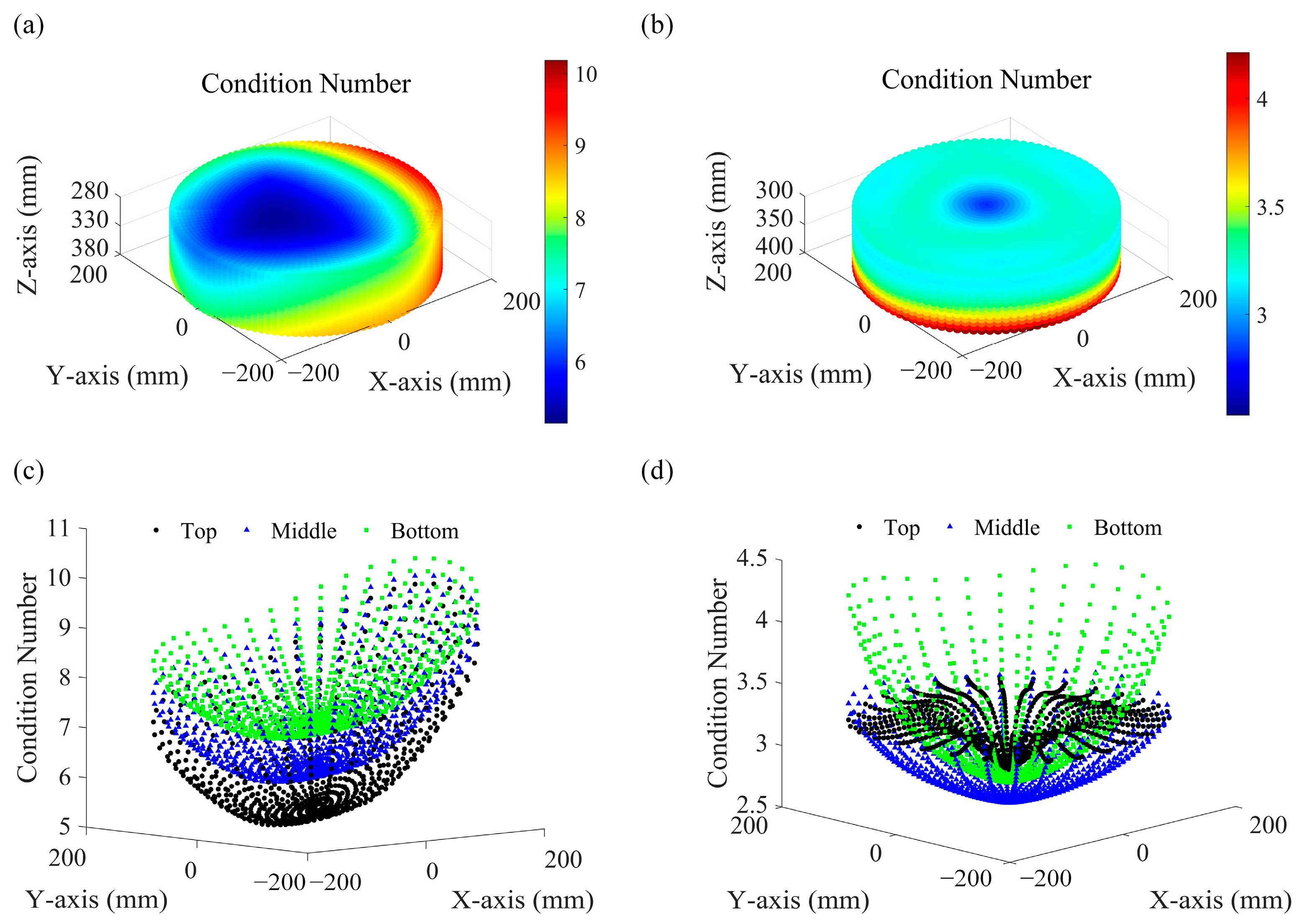
The local and global conditioning indices k , k ¯ , and k ~ of the TriVariant and the Delta robot are summarized in Table 2. The spatial distribution of the condition number k of the TriVariant within the designed workspace Wt is shown in Figure 4a, and that of the Delta robot is shown in 4b. Similarly, the condition numbers of the TriVariant and the Delta robot across the top, middle, and bottom layers of Wt are presented in Figure 4c,d, respectively. As illustrated, the TriVariant exhibits higher mean and standard deviation values of the condition number compared to the Delta robot, indicating slightly reduced dexterity within the designed workspace.
In addition to the condition number, the maximum and minimum singular values of the Jacobian matrix at a given position i, denoted by σmax,i and σmin,i, are employed as indices to identify regions of the designed workspace where the end-effector can achieve either high velocities or fine pose resolution [39]. The singular values of a Jacobian matrix J are defined as the non-negative square roots of the eigenvalues of the symmetric matrixJTJ.
σ k , i = λ k , i ( J T J )           k = 1 , 2 , 3
where λk,i denotes the k-th eigenvalue. The maximum and minimum singular values are obtained by
σ max , i = max σ 1 , i , σ 2 , i , σ 3 , i
σ min , i = min σ 1 , i , σ 2 , i , σ 3 , i
In fact, the singular values of the Jacobian quantify how joint velocities are mapped into end-effector velocities. A larger singular value corresponds to a direction in which end-effector velocity is amplified, while a smaller singular value corresponds to a direction where motion is reduced or lost. in the limiting case, a singular value of zero indicates a singular configuration [40].
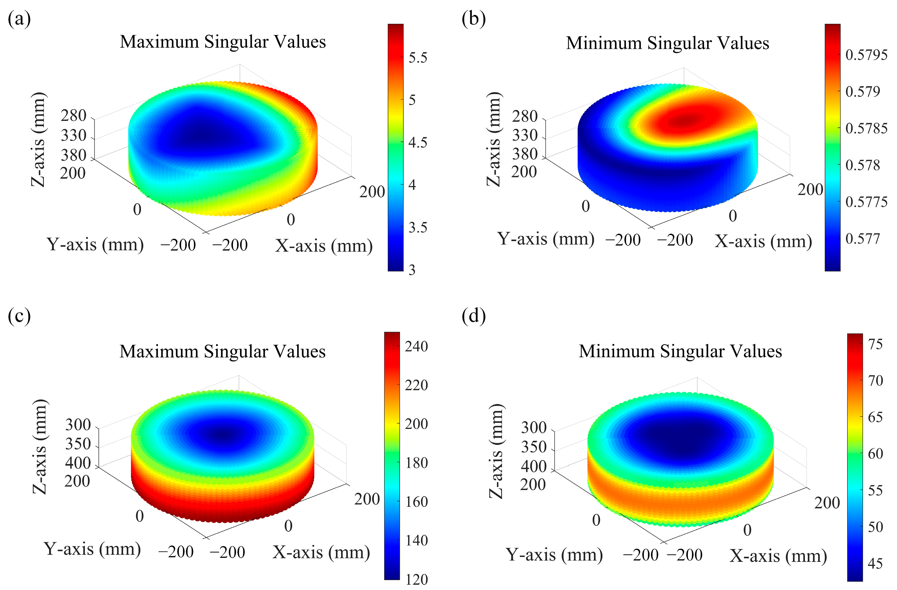
For both the TriVariant and the Delta robot, the singular values σmax,i and σmin,i are evaluated throughout the designed workspace Wt using the design parameters given in Table 1. The distributions of the maximum and minimum singular values of the TriVariant are shown in Figure 5a,b, respectively, while those of the Delta robot are illustrated in Figure 5c,d. As summarized in Table 2, the singular values σ of the TriVariant range from 0.577 to 5.886., i.e., all σmax,i values are less than or equal to 5.886, and all σmin,i values are greater than or equal to 0.577. By contrast, the singular values σ of the Delta robot lie within a much larger interval, from 42.503 to 247.027. These results indicate that the Delta robot achieves higher end-effector velocities, while the TriVariant offers finer end-effector resolution. Neither robot exhibits a singular configuration within the designed workspace.

5. Trajectory Tracking Experiments of the TriVariant

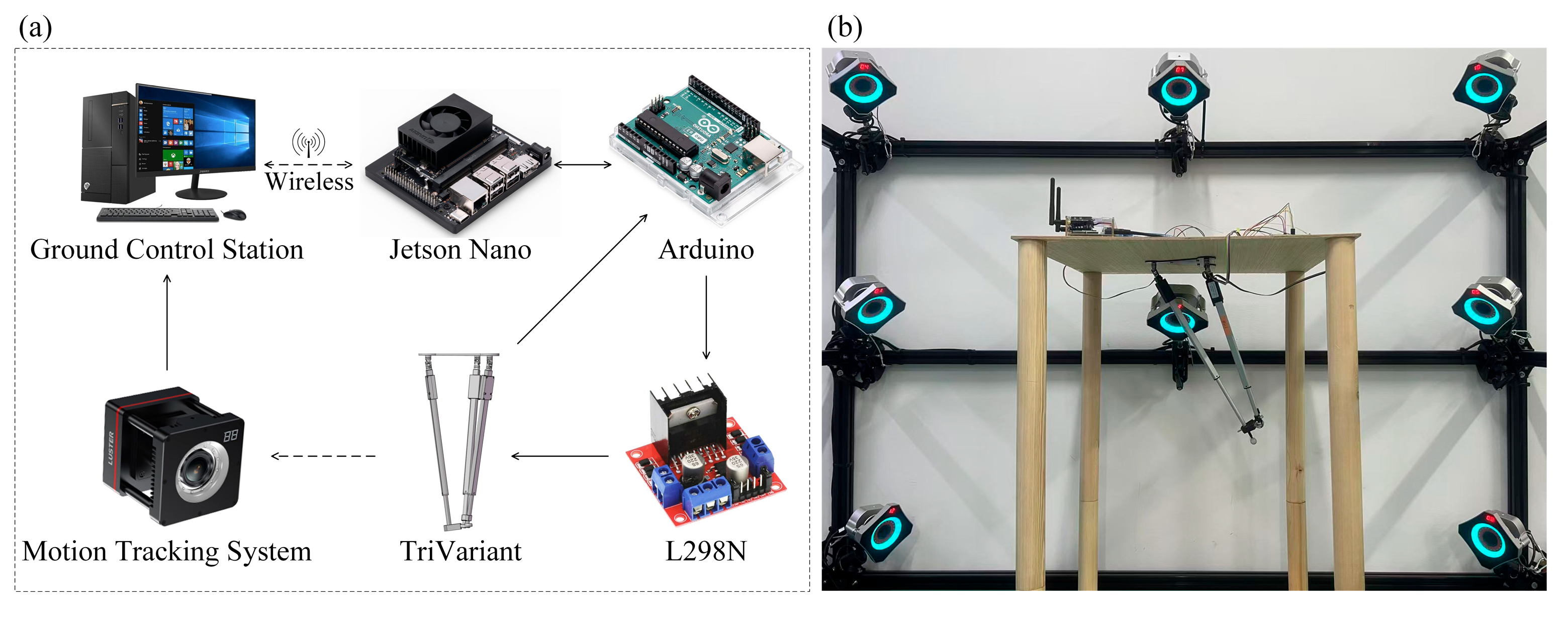
To evaluate the trajectory tracking performance of the TriVariant, a 479 g prototype was constructed according to the design parameters listed in Table 1. The prototype employed three linear DC motors (Hoodland, IP60; Hoodland Technology Co., Ltd., Wenzhou, China) integrated with Hall-effect displacement transducers. Each motor provides a maximum linear speed of 30 mm/s, an output force of 20 N, and a self-locking force of 20 N. Each displacement transducer offers a resolution of 38 pulses per millimeter of motor displacement. To control motor positions, the pulses generated by displacement transducers during motion were counted, and the motors were stopped once the target positions were reached, with an allowable error of up to three pulses. A control system consisting of a Jetson Nano (NVIDIA, Santa Clara, CA, USA), an Arduino Uno (Arduino, Milan, Italy), and two L298N drivers (STMicroelectronics, Geneva, Switzerland) was implemented, as illustrated in Figure 6, and the prototype was mounted on a wooden test platform. No rated load was applied to the TriVariant; instead, a marker was attached to the end of the moving platform, and its motion was recorded using the FZMotion motion tracking system. All experiments were conducted indoors to eliminate airflow interference.
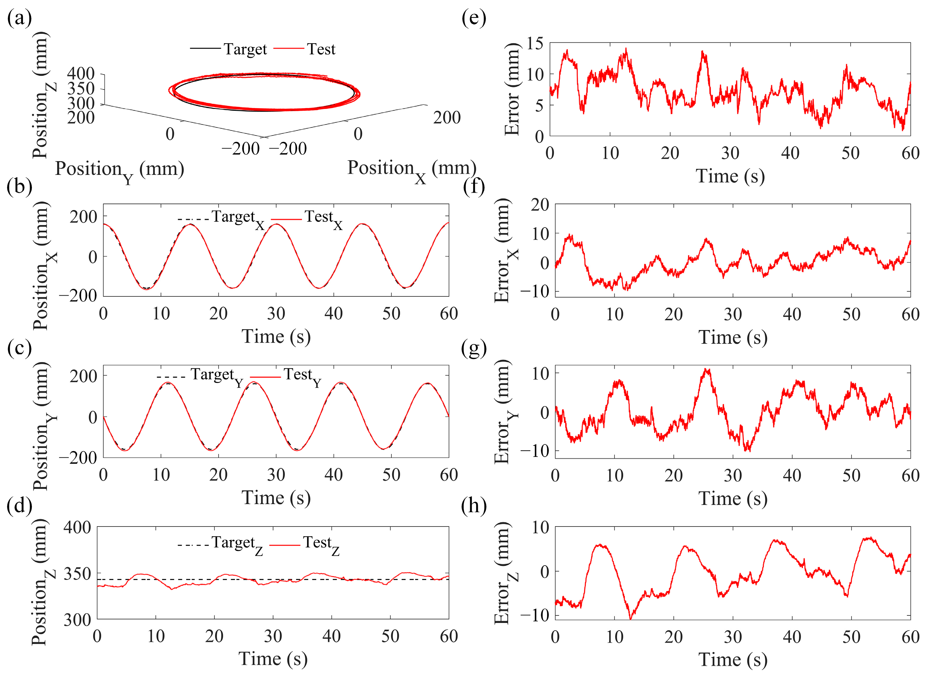
A circular trajectory with a radius of 0.8R1 was defined for the end-effector of the TriVariant. The input commands for the three linear DC motors were computed through inverse kinematics. The motor trajectories and corresponding tracking errors during experiments are shown in Figure 7. Results demonstrate that the motors effectively follow the input signals, with tracking errors remaining below 0.5 mm. The end-effector tracking errors of the TriVariant are presented in Figure 8 and Table 3. The experimental results indicate that the TriVariant can follow the desired trajectory with a mean absolute error (MAE) of 7.719 mm. The observed errors are primarily attributed to two factors. First, the Hall-effect displacement transducers are not perfectly integrated with the linear DC motors, causing some pulses to be unrecorded during motor movement. As a result, the motors may not stop precisely at their target positions, leading to reduced accuracy. Second, the universal and spherical joints used in assembling the TriVariant prototype exhibit clearance, which reduces the stability of the moving platform. Specifically, when an external force is applied, the platform may deviate by up to 4 mm even if all three linear DC motors are locked. In addition, the instability of the wooden test platform shown in Figure 6b contributes slightly to the overall tracking errors.
A MFR was developed by integrating the TriVariant with a UAV. The UAV’s roll, pitch, yaw, and thrust were controlled via a Pixhawk, while the TriVariant was managed by a Jetson Nano. Figure 9 illustrates snapshots of the TriVariant-integrated MFR operating at various positions, highlighting its suitability for aerial manipulation, particularly in scenarios where all limbs must be mounted beneath the UAV.

6. Discussions

This paper focuses on comparing the TriVariant and the Delta robot in terms of dimension and dexterity, while other aspects such as stiffness [41] and motion/force transmissibility [42] could be further investigated for a more comprehensive evaluation. The TriVariant prototype was assembled using low-cost linear DC motors, Hall-effect displacement transducers, and joints, with each motor (including a built-in transducer) costing approximately USD 20. To enhance accuracy, future prototypes could employ high-resolution linear motors and low-clearance joints. Moreover, the payload capacity of the current prototype was not evaluated in experiments; this could be analyzed through force transmissibility in conjunction with the maximum output force of the linear motors.
Both the TriVariant and the Delta robot have three DoFs. Conventionally, three actuators are employed, each mounted on one limb, to adjust the position of the moving platform, which is also the configuration adopted in our performance analysis. To further improve force transmissibility, dynamic performance, and energy efficiency, future work could explore kinematic redundancy by adding actuated joints or kinematic chains [43,44,45]. In addition, the high-speed motion of the TriVariant may induce instability in the MFR. Therefore, optimizing its design parameters and developing coordinated trajectory planning strategies for both the UAV and the TriVariant merit further investigation [46].

7. Conclusions

This paper presented the kinematic modeling and performance comparison of the TriVariant and the Delta robot. Analytical results showed that, within a cylindrical task workspace characterized by a relatively large diameter and moderate height, the TriVariant offers a more compact structure than the Delta robot, despite its slightly reduced dexterity. A prototype of the TriVariant was developed, and experimental results reveal that it can track the desired trajectory with a MAE of 7.719 mm. Furthermore, A MFR was constructed by integrating the TriVariant with a UAV, demonstrating TriVariant’s suitability for aerial manipulation tasks in which all limbs are required to be positioned beneath the UAV.
Future work will focus on optimizing the design parameters of the TriVariant and integrating it with a two-DoF head for directional adjustment. In addition, advanced control algorithms will be developed to enhance its environmental interaction capabilities, including object picking, pulling, and pushing.

Author Contributions

Z.J. conceived the study and wrote the article, Y.L. conducted data gathering, Y.Z. performed statistical analyses, M.L. provided critical revisions to the manuscript, and C.L. validated and funded the study. All authors have read and agreed to the published version of the manuscript.

Funding

This research was funded by supported by the China Postdoctoral Science Foundation under grant 2025M771333, the National Key Research and Development Program of China under grant 2022YFB4702202, and the Jiangsu Provincial Key Technology R&D Program under grant BE2021009-02.

Data Availability Statement

The data used to support the findings of this study are available from the corresponding author upon request.

Conflicts of Interest

The authors declare no conflicts of interest.

References

  1. Meng, X.; He, Y.; Han, J. Survey on aerial manipulator: System, modeling, and control. Robotica 2020, 38, 1288–1317. [Google Scholar] [CrossRef]
  2. Ahmed, F.; Mohanta, J.; Keshari, A.; Yadav, P.S. Recent advances in unmanned aerial vehicles: A review. Arab. J. Sci. Eng. 2022, 47, 7963–7984. [Google Scholar] [CrossRef] [PubMed]
  3. Ladig, R.; Paul, H.; Miyazaki, R.; Shimonomura, K. Aerial manipulation using multirotor UAV: A review from the aspect of operating space and force. J. Robot. Mechatron. 2021, 33, 196–204. [Google Scholar] [CrossRef]
  4. Xilun, D.; Pin, G.; Kun, X.; Yushu, Y. A review of aerial manipulation of small-scale rotorcraft unmanned robotic systems. Chin. J. Aeronaut. 2019, 32, 200–214. [Google Scholar] [CrossRef]
  5. Bodie, K.; Brunner, M.; Pantic, M.; Walser, S.; Pfändler, P.; Angst, U.; Siegwart, R.; Nieto, J. Active interaction force control for contact-based inspection with a fully actuated aerial vehicle. Trans. Robot. 2020, 37, 709–722. [Google Scholar] [CrossRef]
  6. Brunner, M.; Rizzi, G.; Studiger, M.; Siegwart, R.; Tognon, M. A planning-and-control framework for aerial manipulation of articulated objects. IEEE Robot. Autom. Lett. 2022, 7, 10689–10696. [Google Scholar] [CrossRef]
  7. Kim, S.-J.; Lee, D.-Y.; Jung, G.-P.; Cho, K.-J. An origami-inspired, self-locking robotic arm that can be folded flat. Sci. Robot. 2018, 3, eaar2915. [Google Scholar] [CrossRef]
  8. Bartelds, T.; Capra, A.; Hamaza, S.; Stramigioli, S.; Fumagalli, M. Compliant aerial manipulators: Toward a new generation of aerial robotic workers. IEEE Robot. Autom. Lett. 2016, 1, 477–483. [Google Scholar] [CrossRef]
  9. Xu, M.; Hu, A.; Wang, H. Image-based visual impedance force control for contact aerial manipulation. IEEE Trans. Autom. Sci. Eng. 2022, 20, 518–527. [Google Scholar] [CrossRef]
  10. Zhong, H.; Miao, Z.; Wang, Y.; Mao, J.; Li, L.; Zhang, H.; Chen, Y.; Fierro, R. A practical visual servo control for aerial manipulation using a spherical projection model. IEEE Trans. Ind. Electron. 2019, 67, 10564–10574. [Google Scholar] [CrossRef]
  11. Emami, S.A.; Banazadeh, A. Simultaneous trajectory tracking and aerial manipulation using a multi-stage model predictive control. Aerosp. Sci. Technol. 2021, 112, 106573. [Google Scholar] [CrossRef]
  12. Imanberdiyev, N.; Sood, S.; Kircali, D.; Kayacan, E. Design, development and experimental validation of a lightweight dual-arm aerial manipulator with a COG balancing mechanism. Mechatronics 2022, 82, 102719. [Google Scholar] [CrossRef]
  13. Cacace, J.; Orozco-Soto, S.M.; Suarez, A.; Caballero, A.; Orsag, M.; Bogdan, S.; Vasiljevic, G.; Ebeid, E.; Rodriguez, J.A.A.; Ollero, A. Safe local aerial manipulation for the installation of devices on power lines: Aerial-core first year results and designs. Appl. Sci. 2021, 11, 6220. [Google Scholar] [CrossRef]
  14. Peng, R.; Wang, Y.; Lu, M.; Lu, P. A dexterous and compliant aerial continuum manipulator for cluttered and constrained environments. Nat. Commun. 2025, 16, 889. [Google Scholar] [CrossRef] [PubMed]
  15. Uthayasooriyan, A.; Vanegas, F.; Jalali, A.; Digumarti, K.M.; Janabi-Sharifi, F.; Gonzalez, F. Tendon-Driven Continuum Robots for Aerial Manipulation—A Survey of Fabrication Methods. Drones 2024, 8, 269. [Google Scholar] [CrossRef]
  16. Guo, X.; Tang, W.; Qin, K.; Zhong, Y.; Xu, H.; Qu, Y.; Li, Z.; Sheng, Q.; Gao, Y.; Yang, H. Powerful UAV manipulation via bioinspired self-adaptive soft self-contained gripper. Sci. Adv. 2024, 10, eadn6642. [Google Scholar] [CrossRef]
  17. Wang, Z.; Freris, N.M.; Wei, X. SpiRobs: Logarithmic spiral-shaped robots for versatile grasping across scales. Device 2024, 3, 100646. [Google Scholar] [CrossRef]
  18. Carbone, G.; Ceccarelli, M.; Oliveira, P.; Saramago, S.F.; Carvalho, J.C.M. An optimum path planning for Cassino parallel manipulator by using inverse dynamics. Robotica 2008, 26, 229–239. [Google Scholar] [CrossRef]
  19. Gan, D.; Liao, Q.; Dai, J.S.; Wei, S. Design and kinematics analysis of a new 3CCC parallel mechanism. Robotica 2010, 28, 1065–1072. [Google Scholar] [CrossRef]
  20. Bodie, K.; Brunner, M.; Allenspach, M. Omnidirectional Tilt-Rotor Flying Robots for Aerial Physical Interaction: Modelling, Control, Design and Experiments; Springer Nature: Cham, Switzerland, 2023; Volume 157. [Google Scholar]
  21. Zhang, K.; Chermprayong, P.; Xiao, F.; Tzoumanikas, D.; Dams, B.; Kay, S.; Kocer, B.B.; Burns, A.; Orr, L.; Alhinai, T. Aerial additive manufacturing with multiple autonomous robots. Nature 2022, 609, 709–717. [Google Scholar] [CrossRef]
  22. Cao, H.; Li, Y.; Liu, C.; Zhao, S. ESO-based robust and high-precision tracking control for aerial manipulation. IEEE Trans. Autom. Sci. Eng. 2023, 21, 2139–2155. [Google Scholar] [CrossRef]
  23. Bodie, K.; Tognon, M.; Siegwart, R. Dynamic end effector tracking with an omnidirectional parallel aerial manipulator. IEEE Robot. Autom. Lett. 2021, 6, 8165–8172. [Google Scholar] [CrossRef]
  24. Pierrot, F.; Reynaud, C.; Fournier, A. DELTA: A simple and efficient parallel robot. Robotica 1990, 8, 105–109. [Google Scholar] [CrossRef]
  25. Yang, X.; Feng, Z.; Liu, C.; Ren, X. A Geometric Method for Kinematics of Delta Robot and Its Path Tracking Control. In Proceedings of the 2014 14th International Conference on Control, Automation and Systems (ICCAS), Seoul, Republic of Korea, 22–25 October 2014; pp. 509–514. [Google Scholar]
  26. Dastjerdi, A.H.; Sheikhi, M.M.; Masouleh, M.T. A complete analytical solution for the dimensional synthesis of 3-DOF delta parallel robot for a prescribed workspace. Mech. Mach. Theory 2020, 153, 103991. [Google Scholar] [CrossRef]
  27. Brinker, J.; Corves, B.; Takeda, Y. Kinematic performance evaluation of high-speed Delta parallel robots based on motion/force transmission indices. Mech. Mach. Theory 2018, 125, 111–125. [Google Scholar] [CrossRef]
  28. Keemink, A.Q.; Fumagalli, M.; Stramigioli, S.; Carloni, R. Mechanical design of a manipulation system for unmanned aerial vehicles. In Proceedings of the 2012 IEEE International Conference on Robotics and Automation, Saint Paul, MN, USA, 14–18 May 2012; pp. 3147–3152. [Google Scholar]
  29. Fumagalli, M.; Naldi, R.; Macchelli, A.; Carloni, R.; Stramigioli, S.; Marconi, L. Modeling and control of a flying robot for contact inspection. In Proceedings of the 2012 IEEE/RSJ International Conference on Intelligent Robots and Systems, Vilamoura, Portugal, 7–12 October 2012; pp. 3532–3537. [Google Scholar]
  30. Scholten, J.L.; Fumagalli, M.; Stramigioli, S.; Carloni, R. Interaction control of an UAV endowed with a manipulator. In Proceedings of the 2013 IEEE International Conference on Robotics and Automation, Karlsruhe, Germany, 6–10 May 2013; pp. 4910–4915. [Google Scholar]
  31. Fumagalli, M.; Naldi, R.; Macchelli, A.; Forte, F.; Keemink, A.Q.; Stramigioli, S.; Carloni, R.; Marconi, L. Developing an aerial manipulator prototype: Physical interaction with the environment. IEEE Robot. Autom. Mag. 2014, 21, 41–50. [Google Scholar] [CrossRef]
  32. Danko, T.W.; Chaney, K.P.; Oh, P.Y. A parallel manipulator for mobile manipulating UAVs. In Proceedings of the 2015 IEEE International Conference on Technologies for Practical Robot Applications (TePRA), Boston, MA, USA, 11–12 May 2015; pp. 1–6. [Google Scholar]
  33. Zhang, K.; Hao, G.; Pakrashi, V.; Murphy, J.; Long, P. Design of a 6-DOF Aerial Hybrid Cable-Driven Parallel Manipulator. In Proceedings of the 2024 20th IEEE/ASME International Conference on Mechatronic and Embedded Systems and Applications (MESA), Genova, Italy, 2–4 September 2024; pp. 1–8. [Google Scholar]
  34. Russo, M.; Zhang, D.; Liu, X.-J.; Xie, Z. A review of parallel kinematic machine tools: Design, modeling, and applications. Int. J. Mach. Tools Manuf. 2024, 196, 104118. [Google Scholar] [CrossRef]
  35. Huang, T.; Li, M.; Zhao, X.; Mei, J.; Chetwynd, D.G.; Hu, S.J. Conceptual design and dimensional synthesis for a 3-DOF module of the TriVariant-a novel 5-DOF reconfigurable hybrid robot. Trans. Robot. 2005, 21, 449–456. [Google Scholar] [CrossRef]
  36. Li, M.; Huang, T.; Mei, J.; Zhao, X.; Chetwynd, D.G.; Hu, S.J. Dynamic formulation and performance comparison of the 3-DOF modules of two reconfigurable PKM—The tricept and the trivariant. J. Mech. Des. 2005, 127, 1129–1136. [Google Scholar] [CrossRef]
  37. Li, M.; Huang, T.; Chetwynd, D.G.; Hu, S.J. Forward position analysis of the 3-DOF module of the TriVariant: A 5-DOF reconfigurable hybrid robot. J. Mech. Des. 2006, 128, 319–322. [Google Scholar] [CrossRef]
  38. Zargarbashi, S.; Khan, W.; Angeles, J. The Jacobian condition number as a dexterity index in 6R machining robots. Robot. Comput.-Integr. Manuf. 2012, 28, 694–699. [Google Scholar] [CrossRef]
  39. Pond, G.; Carretero, J.A. Quantitative dexterous workspace comparison of parallel manipulators. Mech. Mach. Theory 2007, 42, 1388–1400. [Google Scholar] [CrossRef]
  40. Murray, R.M.; Li, Z.; Sastry, S.S. A Mathematical Introduction to Robotic Manipulation; CRC Press: Boca Raton, FL, USA, 2017. [Google Scholar]
  41. Liu, H.; Huang, T.; Chetwynd, D.G.; Kecskeméthy, A. Stiffness modeling of parallel mechanisms at limb and joint/link levels. Trans. Robot. 2017, 33, 734–741. [Google Scholar] [CrossRef]
  42. Xie, F.; Liu, X.-J.; Zhou, Y. Optimization of a redundantly actuated parallel kinematic mechanism for a 5-degree-of-freedom hybrid machine tool. Proc. Inst. Mech. Eng. Part B J. Eng. Manufact. 2014, 228, 1630–1641. [Google Scholar] [CrossRef]
  43. Abadi, B.N.R.; Farid, M.; Mahzoon, M. Redundancy resolution and control of a novel spatial parallel mechanism with kinematic redundancy. Mech. Mach. Theory 2019, 133, 112–126. [Google Scholar] [CrossRef]
  44. Nouri Rahmat Abadi, B.; Mahzoon, M.; Farid, M. Singularity-free trajectory planning of a 3-RP RR planar kinematically redundant parallel mechanism for minimum actuating effort. Iran. J. Sci. Technol. Trans. Mech. Eng. 2019, 43, 739–751. [Google Scholar] [CrossRef]
  45. Nouri Rahmat Abadi, B.; Carretero, J.A. Modeling and real-time motion planning of a class of kinematically redundant parallel mechanisms with reconfigurable platform. J. Mech. Robot. 2023, 15, 021004. [Google Scholar] [CrossRef]
  46. Mirnajafizadeh, S.; Shafei, A. A Unified Framework for Dynamic Analysis and Path Tracking Control of Multi—Rotor Aerial Manipulators. Int. J. Mech. Syst. Dyn. 2025. [Google Scholar] [CrossRef]
Figure 1. (a) The TriVariant mounted on a UAV. (b) Kinematic structure of the TriVariant.
Machines 13 00926 g001
Figure 2. (a) The Delta robot integrated with a UAV. (b) Schematic diagram of the Delta robot.
Machines 13 00926 g002
Figure 3. (a) Workspace of the TriVariant. (b) Workspace of the Delta robot.
Machines 13 00926 g003
Figure 4. Condition numbers of the TriVariant and the Delta robot. (a) Condition number of the TriVariant within the workspace. (b) Condition number of the Delta robot within the workspace. (c) Condition number of the TriVariant at top, middle, and bottom layers of the workspace. (d) Condition number of the Delta robot at top, middle, and bottom layers of the workspace.
Machines 13 00926 g004
Figure 5. Maximum and minimum singular values of the TriVariant and the Delta robot within the designed workspace. (a) Maximum singular values σmax,i of the TriVariant. (b) Minimum singular values σmin,i of the TriVariant. (c) Maximum singular values σmax,i of the Delta robot. (d) Minimum singular values σmin,i of the Delta robot.
Machines 13 00926 g005
Figure 6. (a) Experimental control architecture and (b) prototype of the TriVariant.
Machines 13 00926 g006
Figure 7. Trajectories and tracking errors of the three linear motors. (a) Trajectory of the motor q1. (b) Trajectory of the motor q2. (c) Trajectory of the motor q3. (d) Tracking errors of the motor q1. (e) Tracking errors of the motor q2. (f) Tracking errors of the motor q3.
Machines 13 00926 g007
Figure 8. Trajectories and tracking errors of the TriVariant. (a) Trajectory of the TriVariant. (b) Trajectory of the TriVariant in x-direction. (c) Trajectory of the TriVariant in y-direction. (d) Trajectory of the TriVariant in z-direction. (e) Tracking errors of the TriVariant. (f) Tracking errors of the TriVariant in x-direction. (g) Tracking errors of the TriVariant in y-direction. (h) Tracking errors of the TriVariant in z-direction.
Machines 13 00926 g008
Figure 9. Snapshots of the TriVariant-integrated MFR operating at various positions. (a) Left. (b) Forward. (c) Right. (d) Backward.
Machines 13 00926 g009
Table 1. Design parameters of the TriVariant and Delta robot for comparison (mm).
TriVariantR1h1H1eabq3minq3maxq1min/q2minq1max/q2max
200100279107.539137.5279488262458
DeltaR2h2H2L1L2r1r2
200100300117.540010022.5
Table 2. The condition numbers and singular values between the TriVariant and the Delta robot.
k ¯ k ~ k m i n k m a x σ
TriVariant6.9350.9545.14410.179[0.577, 5.886]
Delta robot2.9520.2962.5334.213[42.503, 247.027]
Table 3. MAE of the TriVariant during trajectory tracking.
DirectionXYZ3D
MAE (mm)3.4373.7363.9097.719
Disclaimer/Publisher’s Note: The statements, opinions and data contained in all publications are solely those of the individual author(s) and contributor(s) and not of MDPI and/or the editor(s). MDPI and/or the editor(s) disclaim responsibility for any injury to people or property resulting from any ideas, methods, instructions or products referred to in the content.