Article

Effect of Cutting Tool Structures on CFRP Interlaminar Drilling

Department of Mechanical Engineering, Hunan University of Science and Technology, Xiangtan 411201, China
*
Author to whom correspondence should be addressed.
Machines 2025, 13(10), 919; https://doi.org/10.3390/machines13100919
Submission received: 3 September 2025 / Revised: 30 September 2025 / Accepted: 2 October 2025 / Published: 5 October 2025
(This article belongs to the Section Advanced Manufacturing)

Abstract

The interlaminar drilling of CFRPs is a new machining method different from traditional drilling, in which the feed direction of the drill bit is parallel to the interlayer interface. To reasonably select tools for CFRP interlaminar drilling, four different types of tool structures, including twist drills, dagger drills, candlestick drills, and step drills, are employed to conduct interlaminar drilling. The axial force and the morphologies of material damage are extracted, the comprehensive damage factors are calculated, and the relation among tool structures, machining parameters, and outlet damage is analyzed. Results show that the peak axial force induced by the four types of tool structures reduces sequentially. The dagger drill and the candlestick drill tend to cause burrs and large-area surface tears, respectively, while the twist drill and the step drill will lead to more significant 3D tears. Among the four tools, the average comprehensive damage factor produced by twist drills is the smallest, making it more suitable for CFRP interlaminar drilling. In addition, this study establishes a mathematical prediction model for the peak axial force and the comprehensive damage factor and optimizes the process parameter combination of twist drills, with the spindle speed set to 4732.87 r/min and the feed speed to 0.137 mm/r.

1. Introduction

Carbon fiber reinforced composites (CFRPs) have significant application advantages in industrial fields such as wind power generation, aerospace, and military defense due to their high specific strength to stiffness, corrosion resistance, and fatigue resistance [1,2]. With the continuous expansion of the application scope of CFRPs, the requirements of hole-making are also constantly updated. CFRP interlaminar drilling is a new method that differs from traditional CFRP drilling. Its characteristic is that the tool feed direction is parallel to the direction of the material interlaminar interface, which is significantly different from the direction perpendicular to the interlaminar interface in traditional drilling, as shown in Figure 1. At present, there is a clear demand for CFRP interlaminar drilling, such as the joint connections of robot limbs, the end faces of new energy vehicle battery boxes, and the bolt holes at the roots of wind turbine blades [3]. However, previous studies have shown that the interlaminar drilling of CFRPs is also prone to producing some damage at the outlet compared to the conventional drilling method of CFRPs, such as burrs, delamination, and tears. Moreover, the risk of damage caused by interlaminar drilling is more prominent [4,5,6]. Therefore, effectively controlling the damage during the interlaminar drilling is crucial to ensure the reliable service of CFRP interlaminar drilling components.
Many studies have pointed out that the tool structure has a significant impact on the drilling quality of CFRPs. However, current studies mainly focus on the conventional drilling methods. Bi et al. [7] studied the influence mechanism of different tool structures on burr formation and distribution. The result showed that burr damage was primarily concentrated in the drilling exit area. In addition, the twist drills produced relatively severe burrs, whereas the step drills and the one-shot drills can achieve better processing quality. Hassouna et al. [8] studied the effects of tool rake angle, inclination angle, and cutting-edge radius on the quality of CFRP drilling. The research showed that reducing the rake angle, inclination angle, and cutting-edge radius can help reduce cutting forces. The best drilling effect was achieved when the parameter combination was a rake angle of 20°, tilt angle of 5°, and cutting-edge radius of 0.03 mm. Xu et al. [9] found that the damage, including burrs, tears, and delamination, generated by CFRP drilling exhibited a high sensitivity to tool structure and cutting parameters. When the candlestick drill is used for CFRP drilling, the cutting performance is better than that of the twist drill. Qiu et al. [10,11] found that the wedging and extrusion of the chisel edge of the twist drill had an important impact on the delamination of CFRP, and the stepped drill showed better drilling performance than the twist drill. Jia et al. [12] proposed a new intermittent sawtooth structure for improving the drilling quality of CFRPs. This new drill bit significantly reduced delamination damage while producing nearly six times as many burr-free holes as the one-shot drill. Su et al. [13] achieved significant results in reducing burrs and delamination damage at the drilling outlets of CFRP by designing a new type of biomimetic drill bit. These provided some new ideas for tool innovation. Kim et al. [14] conducted drilling experiments on CFRP laminates using two types of single drill tip angles and one type of double drill tip angle drill bit and pointed out that although a larger drill tip angle could reduce the fiber pull-out area, it may lead to deeper fiber pull-out, thereby increasing surface roughness. This indicates that different types of damage need to be weighed when selecting cutting tools.
Up to now, there has been relatively little research conducted on the interlaminar drilling of CFRPs. Li et al. [3,15] systematically studied the effects of machining parameters on axial force and material damage mechanisms by conducting interlaminar drilling experiments on CFRPs and establishing an axial force prediction model. The results indicated that the axial force variation trend of interlaminar drilling is consistent with that of traditional drilling, but the axial force value of interlaminar drilling is larger. Furthermore, unlike traditional drilling, where uniaxial compressive failure occurs at the interface of composite layers, interlaminar drilling induces uniaxial compressive failure in the interior of composite layers. Geier et al. [16], based on interlaminar drilling experiments on unidirectional CFRPs, compared interlaminar drilling with traditional CFRP drilling and pointed out that the axial force generated by interlaminar drilling is three times that of traditional drilling. Shunmugesh et al. [17] conducted interlaminar drilling experiments on CFRPs by employing different tool materials, investigated the effects of different tool materials on damage during the interlaminar drilling of CFRPs, and further optimized the machining parameters for the structure of a single tool.
In summary, preliminary progress has been achieved in the current research on interlaminar drilling of CFRPs. However, most of the existing studies primarily focus on the adjustment and optimization of process parameters, with limited attention paid to tool structure. Specifically, the inherent mechanism underlying the influence of tool structure on machining quality and damage behavior has not yet been systematically elucidated. In this presented paper, four different types of drill bits, including twist drills, dagger drills, candlestick drills, and step drills, are employed to conduct CFRP interlaminar drilling experiments, and relative drilling force data, morphology characteristics of material damage, and damage factors are deeply studied. All of them are aimed at establishing the mapping relation among tool structures, machining parameters, and outlet damage during interlaminar drilling of CFRP and at providing the practical basis for the rational selection of cutting tools in interlaminar drilling of CFRPs.

2. Experimental Design

2.1. Materials and Equipment

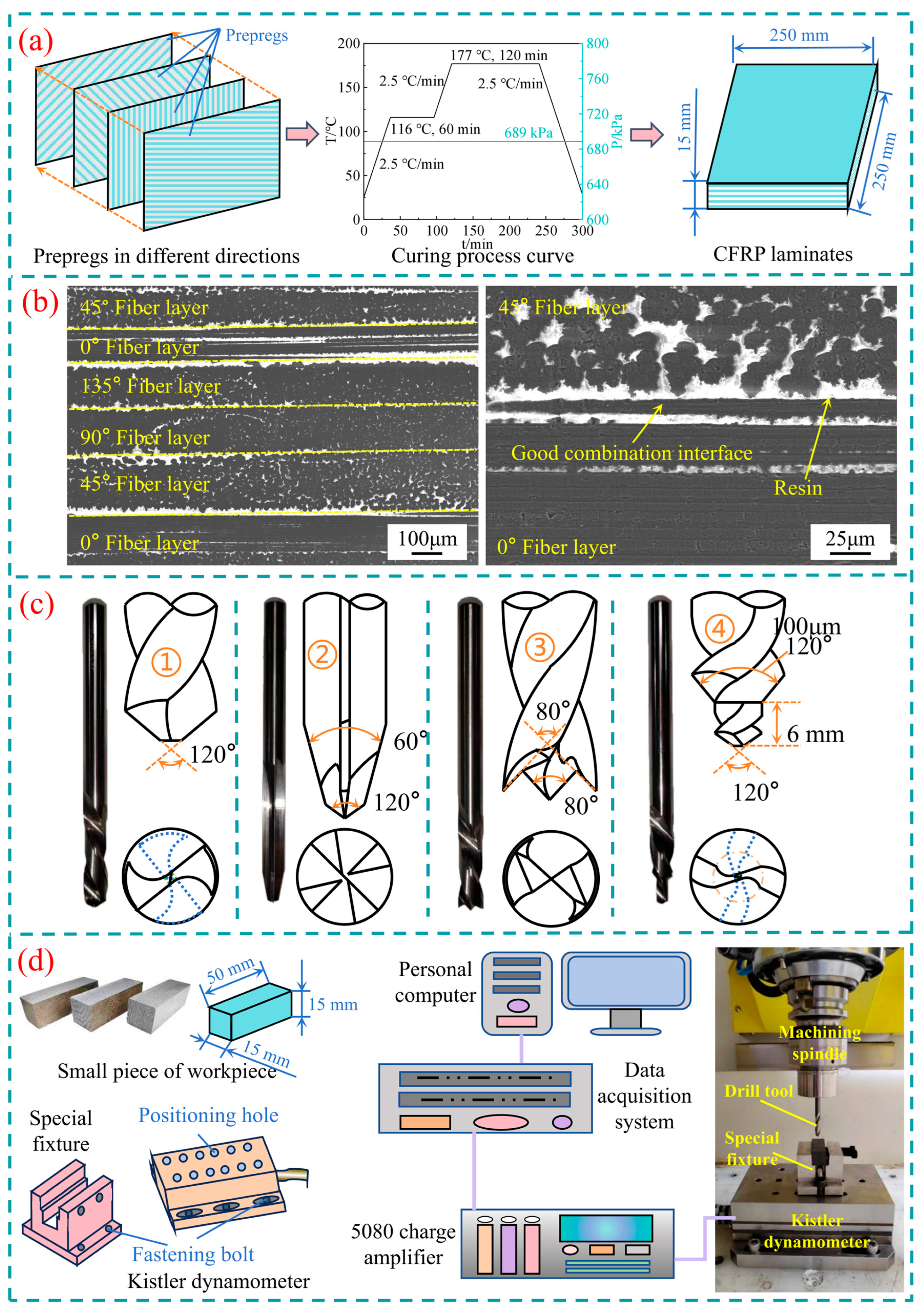
The workpiece materials used in the experiments are CFRP laminates prepared using GY8911/T300 prepreg. Among them, the reinforcement is T300 carbon fiber, the matrix is GY8911 epoxy resin, and the material performance parameters are shown in Table 1. The pre-impregnated material layers are laid manually, with a specific material layer sequence of [90°/45°/0°/135°]30s. After completing the cutting and laying of the prepreg, employ the autoclave (YT-2021-0703, Dalian Yingtian Machinery Manufacturing Co., Ltd., Dalian, China) and apply temperature and pressure according to the manufacturer’s recommended curing process curve to complete the curing of the CFRP laminates (Figure 2a).
To facilitate the positioning and clamping in the experiments, the CFRP laminates are pre-cut into many small pieces with the same size of 50 mm × 15 mm × 15 mm (length × width × thickness). The cross-sectional morphology of the cut workpiece is shown in Figure 2b. To avoid the influence of tool coating on the experimental results, four uncoated hard alloy drill bits (YK30SF, Jiangsu Hangfei Industrial Cutting Tools Co., Ltd., Jiangsu, China) with a diameter of 6 mm are selected. The tool structures and their geometric parameters used in the experiments are shown in Figure 2c.
In this work, CFRP laminates with multidirectional prepregs are drilled on a vertical machining center with four coordinates (KVC800/1, Sichuan Changzheng Machine Tool Group Co., Ltd., Zigong, China) using four different structural tools: they are the twist drill, the dagger drill, the candlestick drill, and the step drill. The machining parameters are shown in Table 2. Measurements of axial force during drilling operations are conducted with a three-way piezoelectric force measuring instrument (Kistler 9253B, Kistler Precision Machinery Equipment (Shanghai) Co., Ltd., Shanghai, China). A data acquisition system consisted of a charge amplifier (Kistler 5080A, Kistler Precision Machinery Equipment (Shanghai) Co., Ltd., Shanghai, China) and a data acquisition card (PCIM-DAS1602/16, Measurement Computing Corporation, Norton, MA, USA), and cutting force acquisition software is employed to extract the axial force curves of different cutting tools at the sampling frequency of 50 KHz. The morphologies of outlet damage are analyzed by the super depth of field microscope (KEYENCE VHX-500FE, Keyence (China) Co., Ltd., Shanghai, China) and the scanning electron microscope (SU3500, Hitachi High Tech Co., Ltd., Tokyo, Japan). The specific experimental process is shown in Figure 2d.

2.2. Damage Assessment

In this work, the comprehensive damage evaluation factor φ is adopted to assess the outlet damage, which refers to the conventional drilling damage evaluation methods [9,18,19,20] and considers the surface morphology of the outlet during interlaminar drilling, as shown in Equation (1).
φ = a φ 1 + b φ 2 + c φ 3 + d φ 4
where φ 1 = i = 1 n S i S nom , φ 2 = j = 1 m S j S nom , φ 3 = q = 1 p S q S nom , φ 4 = D max D nom D nom . i = 1 n S i , j = 1 m S j and q = 1 p S q are the sum of the burr damage area, the surface tear damage area, and the 3D tear damage area, respectively. Snom represents the nominal hole area. Dmax represents the peak diameter of delamination occurring at the hole outlet. Dnom represents the nominal diameter of the machined hole.
Due to the delamination damage at the outlet, it is most likely to reduce the quality of holes, and the 3D tear damage can cause a certain decrease in the strength around the hole; their proportion factors are set to d = 0.35 and c = 0.25, respectively. In addition, the impacts of burr damage and surface tear damage on drilling quality are considered as the same effect, and a + b + c + d = 1. Therefore, when evaluating the damage in this work, a = b = 0.2 is taken.

3. Results and Discussion

3.1. Axial Force Induced by the Tool Structure Characteristics

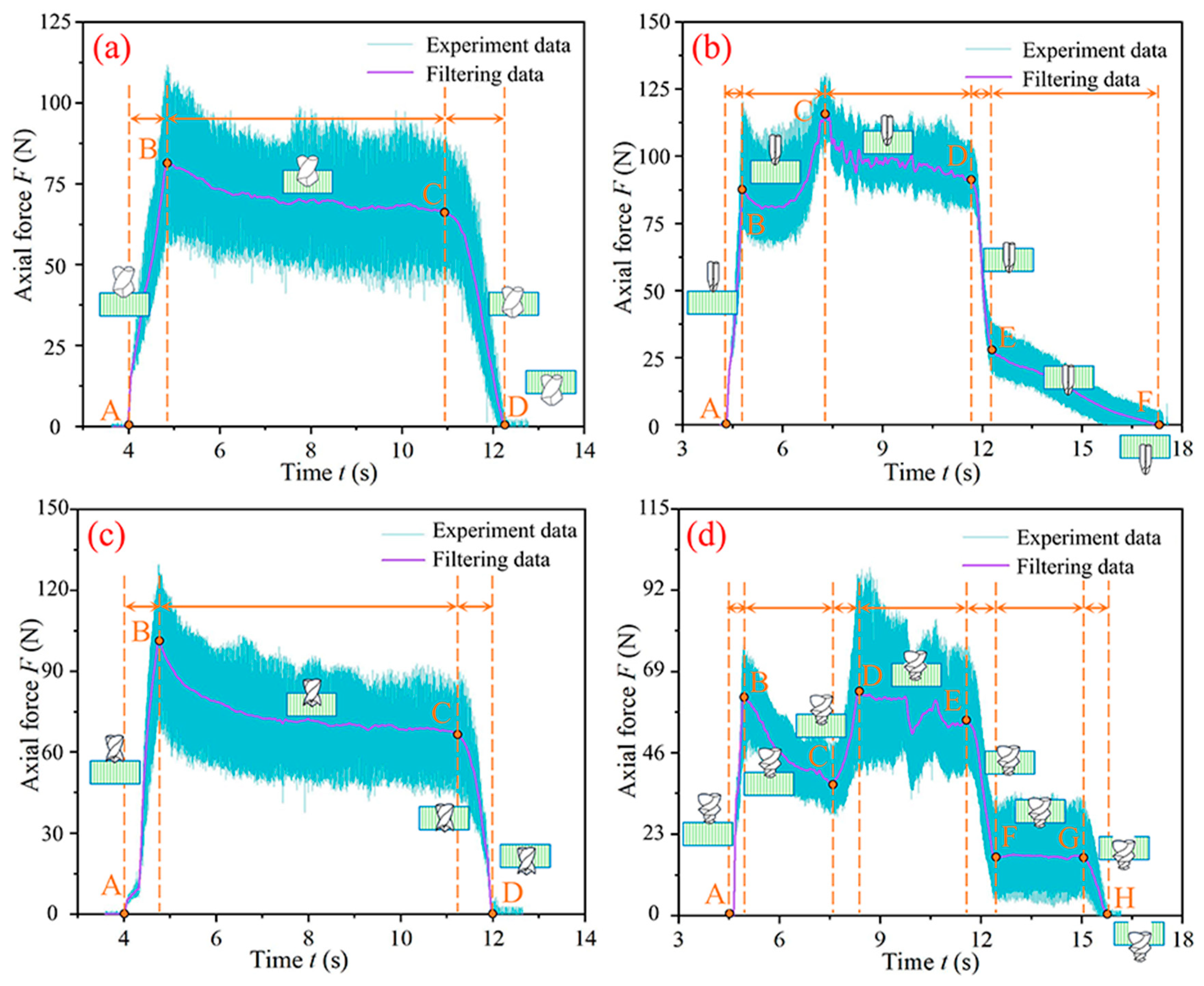
Figure 3 shows the time-varying curves of axial force corresponding to different drill bits. To reduce noise interference and extract effective signal features, the original axial force data was filtered using the built-in Fast Fourier Transform (FFT) low-pass filter in Origin software. It can be observed that the axial force strongly depends on the geometric characteristics of the drill bit. The time-varying curve of axial force under the condition of the traditional twist drill can be divided into three stages, as shown in Figure 3a. In the A–B stage, as the drill bit feeds, the material begins to be drilled until the main cutting edge fully drills into the material, and the axial force reaches its peak value. When the main cutting edge has fully entered into the B–C stage, the axial force shows a slight decreasing trend with the decrease in the thickness of material. This is related to the decrease in material support stiffness. At point C, the main cutting edge begins to drill out the material, and the axial force rapidly decreases until the main cutting edge completely drills out the material. Meanwhile, the axial force decreases to zero (point D).
In the case of interlaminar drilling with the dagger drill, the axial force curve can be divided into five stages, as shown in Figure 3b. In the A–B stage, due to the shorter length of the first cutting edge of the dagger drill and its point angle being bigger than that of the second cutting edge, the axial force increases rapidly with the feed of the tool. As the second cutting edge drills into the material, the axial force increases, but the rate of growth slows down. In the C–D stage, the second cutting edge of the dagger drill fully drills into the material and enters a stable drilling state. At this stage, with the reduction in uncut material thickness, the axial force exhibits a gradual decline as drilling advances. In the D–E stage, the axial force rapidly decreases to the point E due to the influence of the first cutting edge drilling out the material. In the E–F stage, due to the influence of the point angle of the cutting edge and the length of the cutting edge, the rate of reduction for the axial force slows down compared to the D–E stage.
The time-varying curve of axial force under the candlestick drill is similar to the twist drill, as shown in Figure 3c. However, under the same machining parameters, the peak axial force with the candlestick drill increased by 79.15%, and the machining time decreased by 3.7% compared with the twist drill. This is because the axial force of the candlestick drill is distributed more towards the outer edge of the drill bit during the drilling process, resulting in the overall axial force being greater than the twist drill. In addition, although the axial force induced by the drill core of the candlestick drill is smaller than that induced by the twist drill, the rear angle of the outer cutting edge of the candlestick drill is relatively big, and the chip flow angle is more complex, which may cause a certain increase in the axial force.
The axial force curve in the case of the step drill is relatively complex and can be divided into seven stages, as shown in Figure 3d. In the stage where the main cutting edge of the first step of the step drill enters the material (A–B stage), the axial force rapidly increases. The B–C stage is the axial force generated by the first step of step drilling during CFRP interlaminar drilling. The axial force gradually decreases as the tool continues to feed along the material. The main cutting edge of the second step of the step drill begins to drill into the material at point C and fully enters the material at point D. Subsequently, the axial force showed a decreasing trend due to the continuous decrease in thickness of material. The E and G points are the boundary points at which the first and second main cutting edges of the step drill begin to detach from the material, respectively. At the F–G stage, the second step of the step drill starts to drill into the material, and a relatively stable axial force curve is generated.
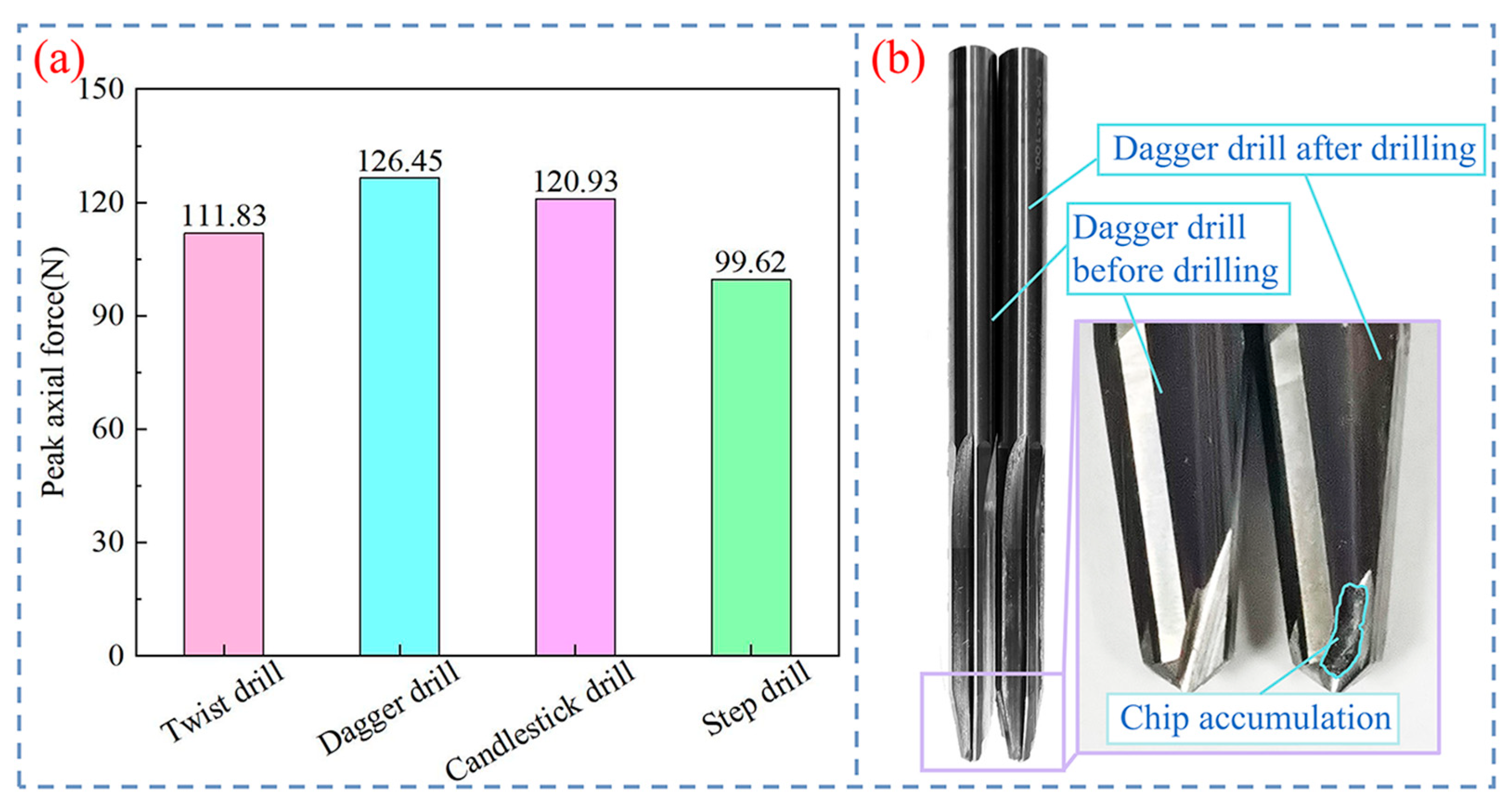
Figure 4a shows the peak axial force generated by four different cutting tools during interlaminar drilling of CFRPs. It can be seen that the peak axial force is more significantly affected by the structural characteristics of the cutting tool. Under the same machining parameters (2000 r/min, 0.06 mm/r), the peak axial force of the twist drill, dagger drill, candlestick drill, and step drill is 111.83 N, 126.45 N, 120.93 N, and 99.62 N, respectively. Obviously, the peak axial force of the dagger drill is higher than that of other tool structures. Compared with the axial force generated by the twist drill, the peak axial force of the dagger drill increased by 13.07%. This is because, that although both the dagger drill and the twist drill are subject to the central concentrated axial force during the drilling process, the straight groove structure of the dagger drill can cause the relatively small movement between the cutting edge and the material when drilling with the low speed, which is not conducive to discharging the chips in time. The residual chips are easily formed into massive chips by the rotation and compression of the cutting tool, which accumulate on the rake face of the cutting edge. This indirectly increases the rake angle of the cutting edge, making the cutting more difficult and resulting in bigger axial force during drilling, as shown in Figure 4b. However, the relatively continuous helical grooves of step drills and twist drills promote the timely discharge of chips, which can better take away some drilling heat and reduce the resistance of chips to the cutting process. Therefore, the axial force generated by the step drill and twist drill is relatively small. In addition, the axial force generated by the chisel edge of the twist drill is known as an important part of the total axial force, but the axial force of the step drill is less than that of the twist drill. The reason is related to the first step of the step drill, which weakens its influence on the axial force.

3.2. Outlet Damage Induced by the Tool Structures

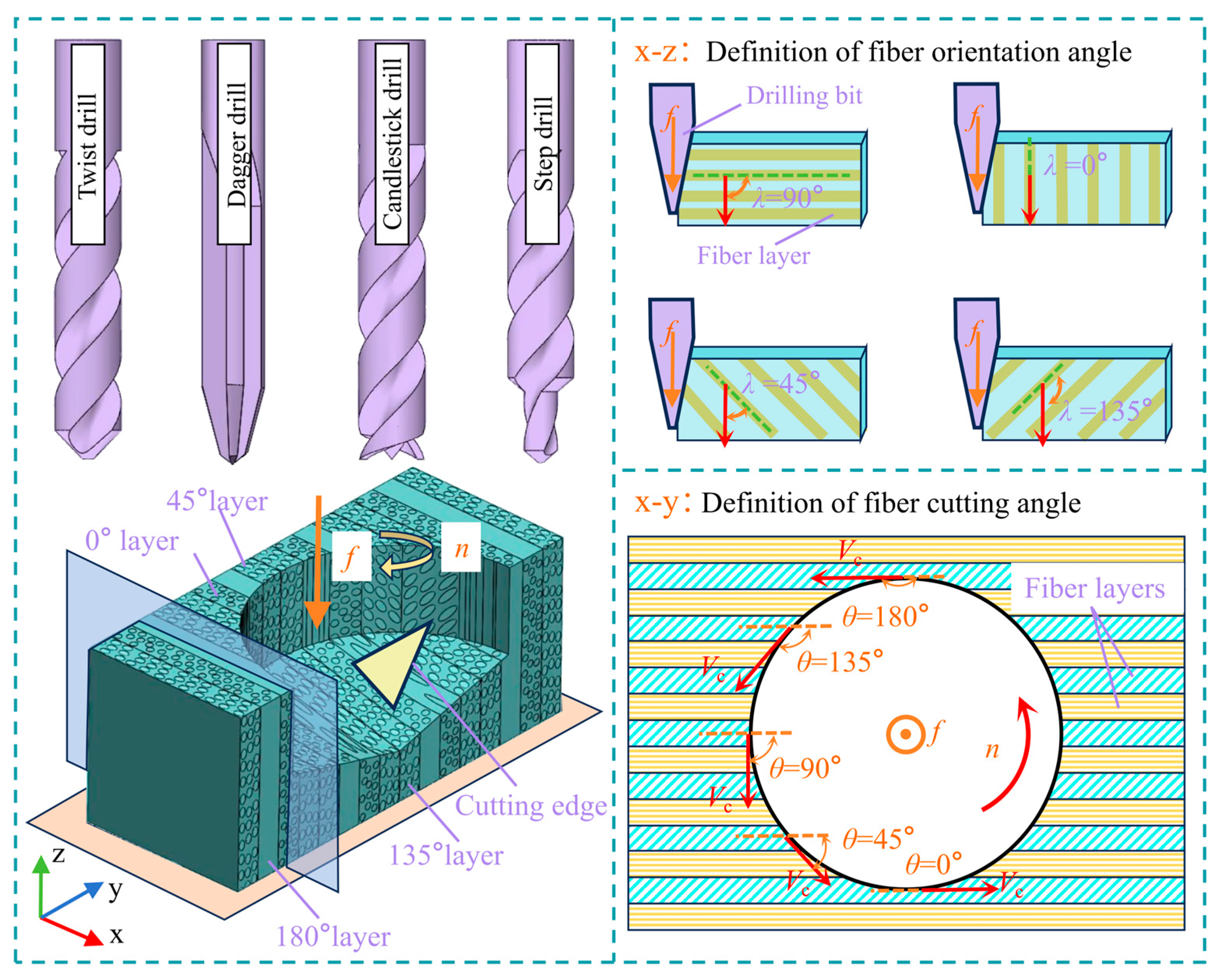
The anticlockwise included angle between the tool feed direction and the fiber orientation is defined as the fiber orientation angle (FOA, γ), and the anticlockwise included angle between the tool cutting direction and the projection of the fiber direction on the outlet surface is defined as the fiber cutting angle (FCA, θ). Due to the layering order of the materials used in this study being 90°/45°/0°/−45°, when conducting the interlaminar drilling of CFRP, the fiber layers can be denoted as γ = 0°, γ = 90°, γ = 45°, and γ = 135°, as shown in Figure 5.
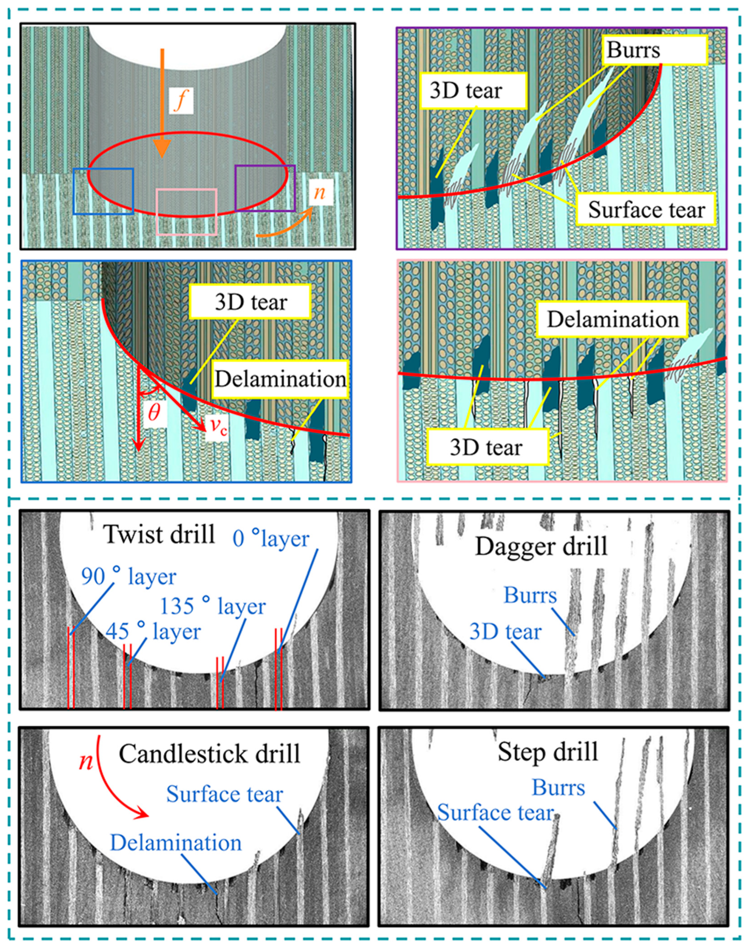
Figure 6 shows the outlet damage morphologies formed during CFRP interlaminar drilling with four different tool structures (n = 2000 r/min, f = 0.04 mm/r). As can be seen, there are varying degrees of burrs, surface tears, 3D tears, and delamination damage around the outlet of the hole, but the scale of each kind of damage is different. Among them, the outlet burrs formed by twist drills are less, but the 3D tear damage is more obvious than that of dagger drills. The dagger drill bit generates numerous burrs with a large coverage area, but there is relatively less 3D tearing damage around the outlet of the hole. This is because the second cutting edge of the dagger drill has a smaller point angle than the twist drill, so that the action area l2 of the axial force on the material at the outlet is smaller than the force area l1 of the material when the twist drill is employed. On the one hand, under the same feed rate, within the fiber layers perpendicular to the feed direction, the constraint effect of the material at the outlet processed by the dagger drill is relatively weak. The fibers of the outlet produce the severe out-of-plane bending under the axial pushing action of the cutting edge and cannot be effectively cut. Thus, the burrs remain at the outlet. Moreover, the uncut fiber bundles are subjected to the repeated thrust force from the cutting edge, resulting in dispersed dendritic burrs. When the fiber layers with an included angle between the twist drill and the feed direction are processed, the force bearing area l2 of the material is large, which makes the uncut material easy to slip along the interface between the fiber layers, and the 3D tear damage around the outlet of the hole is formed. With the axial feed of the drill bit, the cutting thickness and the axial force are reduced by decreasing the angle of the cutting edge. Therefore, the 3D tear damage on the outlet surface induced by the dagger bit is less than that of the twist bit.
Due to the sharp outer corner of the candlestick drill, it can cut off the outlet material in a timely manner. Therefore, there are fewer burrs at the outlet, and a more complete machining surface can be formed, as shown in Figure 6c. When the outer edge corner and the point angle of the drill core are simultaneously drilled into the material, the axial force is composed of a combination of central concentrated load and circumferential distributed load. For the 45° and 135° fiber layers, due to the dispersing effect of the inner and outer cutting edges on the total axial force of drilling, as well as the radial force Fr2 of the outer cutting edge on the uncut material in the hole, the local axial force on the uncut material around the outlet hole is difficult to reach the critical axial force for forming 3D tear damage [21]. Thus, the formation of 3D tear damage can be avoided. But within the 90° fiber layer, the axial force Fz2 provided by the outer edge angle of the drill bit acts on the edge of the hole. As the drill bit feeds axially, the surface material at the outlet arises out-of-plane bending and yielding under the axial force Fz2. When Fz2 exceeds the strength of the fiber/resin interface, the interface may crack and expand along the fiber direction. The fibers that undergo out-of-plane bending will undergo in-plane radial bending under the sharp outer edge corner and the tangential pushing effect of the outer cutting edge. Due to the brittle nature of carbon fiber, uncut burrs are prone to bending, fracture, and detachment from the material. Ultimately, extensive surface tearing damage around the hole is formed.
Compared to the other three drill bits, when using the step drill for CFRP interlaminar drilling, a larger area of 3D tear damage is formed at the outlet, as shown in Figure 6d. This is because, near the outlet surface, the second step’s main cutting edge of the step drill is shorter than the main cutting edge of the traditional twist drill, which results in the relatively concentrated axial force of the step drill on the material. In addition, due to the influence of the first step of the step drill on the drilling of materials, the amount of uncut material at the outlet is reduced, and it is easy to cause out-of-plane bending and 3D tear under the action of axial force without external support. Within the 45° and 135° fiber layers at the outlet, shear slip is more likely to occur at the fiber/resin interface due to the concentrated contact stress of the second main cutting edge, resulting in 3D tear damage. By comparing the outlet damage morphologies under different cutting tools, as shown in Figure 6, the burr damage caused by the step drill is second only to the dagger drill. This is mainly related to the axial force of the step drill being smaller than that of the dagger drill and the out-of-plane bending of the uncut fiber at the outlet caused by the axial force of the second step’s main cutting edge.
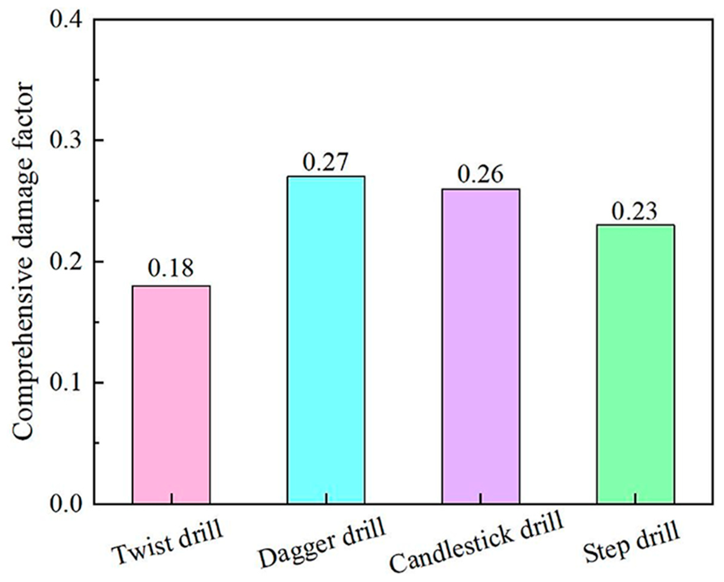
The comprehensive evaluation of the outlet damage morphology generated by different cutting tools under the same machining condition is shown in Figure 7. As can be seen, the comprehensive damage factors produced by the dagger drill, candlestick drill, step drill, and twist drill decrease in turn, which are 0.27, 0.26, 0.23, and 0.18, respectively. Combined with the outlet surface morphologies in Figure 6, it is found that the damage type produced by the dagger drill is mainly the burr damage, the large area of surface tear damage on the outlet is mainly formed by the candlestick drill, and the step drill and twist drill both produce obvious 3D tear damage around the hole. In addition, due to the different fiber direction angles formed between the fibers in the fiber layer and the feed direction, there are significant differences in the types of damage to the outlet material.
Figure 8 illustrates the types of damage within the fiber layer at the outlet of CFRP interlaminar drilling. The outlet burr damage mainly occurs in the fiber layers perpendicular to the feed direction (90° layers) and shows a trend of deviation along the rotation direction of the cutting edge. Moreover, the outlet material is prone to produce surface tear damage around the hole due to the pushing force along the feed direction and the radial rotation torque of the tool acting on the burrs. The surface tear damage shows a decreasing distribution trend towards both sides of the hole with a 90° fiber cutting angle as the symmetrical center, and the distribution of damage morphology is the same as that of CFRP drilling in the traditional direction [11]. Delamination damage mainly occurs at the interlaminar positions of fibers in different directions and is concentrated at the 90° fiber cutting angle on the outlet surface. For the case where the fiber direction angle is 45° or 135°, the fiber/resin interface is prone to slip and form 3D tear damage at the outlet when the outlet material is subjected to the axial thrust of the cutting tool.
Figure 9 shows the influence of tool structure on the single outlet damage factor of CFRP interlaminar drilling under different feed rates at the spindle speed of 4000 r/min. Among them, surface tear damage and outlet burr damage are greatly affected by the tool structures. Taking the feed rate of 0.06 mm/r as an example, when using a twist drill, dagger drill, candlestick drill, and step drill for interlaminar drilling of CFRPs, the burr damage factors are 0.039, 0.232, 0.017, and 0.097, respectively, and the surface tear damage factors are 0.0041, 0.0057, 0.1408, and 0.0104, respectively. Moreover, serious burr damage is easy to occur when using a dagger drill, and the outlet surface tear damage factor is the largest when using a candlestick drill. The 3D tear damage and exit delamination damage are not significantly affected by the tool structure, but regardless of the type of tool structure used, both types of damage exist on the outlet surface. In addition, the inhibition of twist drill on 3D tear damage is not obvious when drilling with the small feed rate. However, with the increase in feed rate, compared with the other three types of drill bits, the twist drill can form smaller 3D tear damage. Therefore, comprehensively considering the damage types of CFRP interlaminar drilling and its impact on machining quality, the twist drill has the smallest comprehensive damage and can effectively inhibit the 3D tear damage when the feed rate increases, which is more suitable for CFRP interlaminar drilling.

3.3. Effect of Machining Parameters on CFRP Interlaminar Drilling

3.3.1. Axial Force During CFRP Interlaminar Drilling

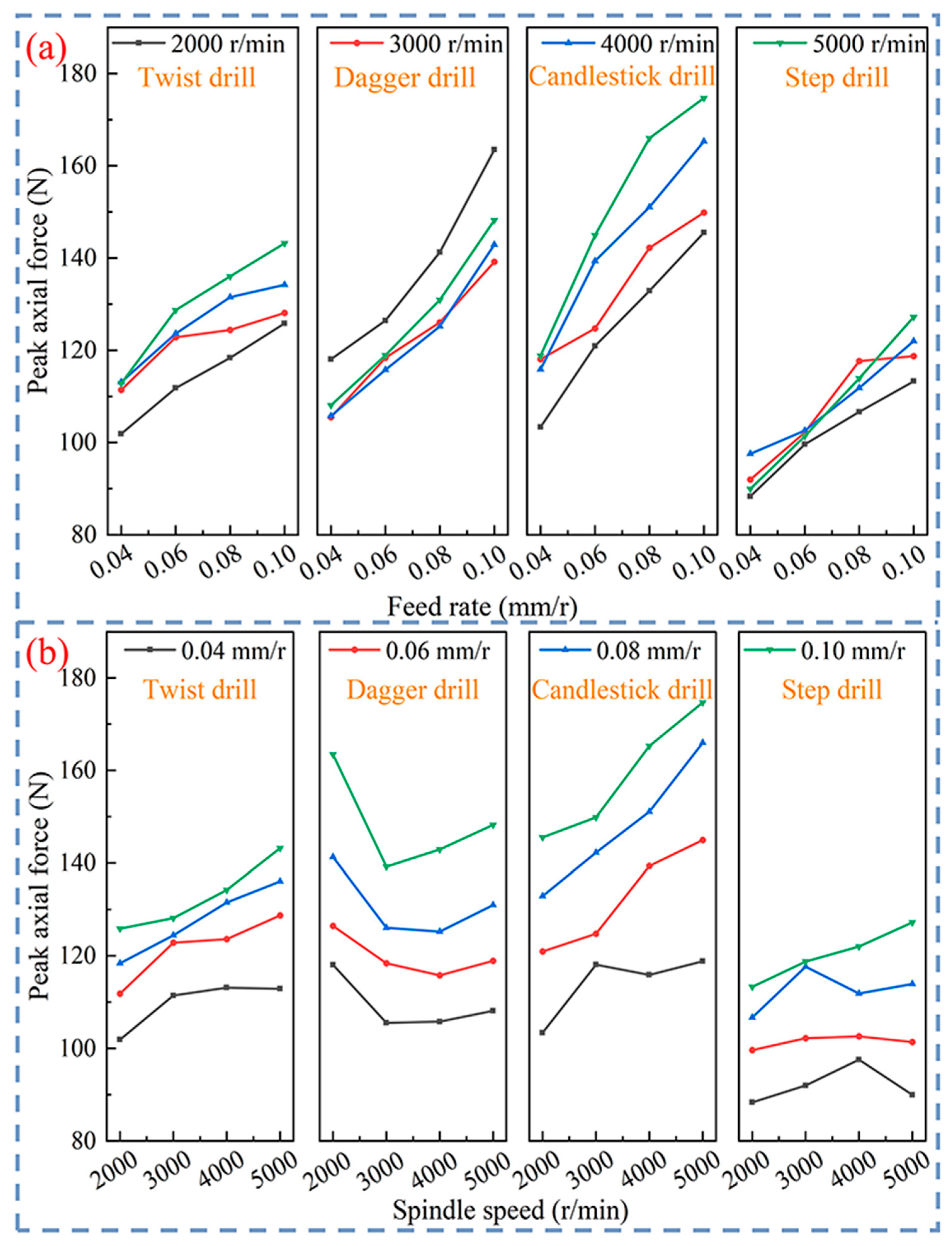
The peak axial force of CFRP interlaminar drilling is extracted under different tool structures and machining parameters, as shown in Figure 10. It can be observed that the peak axial force increases with the increase in feed rate, regardless of the tool structures used. Under certain spindle speed conditions (n = 2000 r/min), the peak axial force of the twist drill, dagger drill, candlestick drill, and step drill can increase by 23.51%, 38.45%, 40.76%, and 28.23%, respectively, when the feed rate increases from 0.04 mm/r to 0.10 mm/r, as can be seen in Figure 10a. This indicates that the axial force of the candlestick drill is most affected by the feed rate, while the axial force of the twist drill is the least.
It can be seen from Figure 10b that, except for the dagger drill, the peak axial force of the other three tool structures slightly increases with the increase in spindle speed. The peak axial force of the three tool structures, except for the dagger drill, increases slightly with the increase in rotational speed. In this work, when the spindle speed increases from 2000 r/min to 5000 r/min, the peak axial force of the twist drill, candlestick drill, and step drill increases by 10.76%~15.11%, 14.93%~24.92%, and 1.22%~6.81%, respectively. Moreover, the peak axial force of the dagger drill shows a trend of first decreasing and then increasing with the increase in spindle speed and reaches the minimum value at the spindle speed of 3000 r/min. The reason is that the unique straight groove structure of the dagger drill makes it difficult for the chips formed during interlaminar drilling at the lower speed to be discharged from the hole and accumulate near the cutting edge under the rotation and compression of the tool. Consequently, the rake angle of the cutting edge is increased, and the axial force with the low spindle speed is bigger than that of the high spindle speed. But the peak axial force of the dagger drill increases by 0.46% to 6.47% in general when the spindle speed increases from 3000 r/min to 5000 r/min.
In summary, the increase in axial force of the dagger drill with spindle speed is the smallest, followed by the step drill, while the axial force of the candlestick drill is most significantly affected by the spindle speed. Therefore, to maintain the relative stability of the axial force and to achieve efficient CFRP interlaminar drilling, the feed rate can be appropriately increased for twist drills, and the spindle speed can be appropriately increased for dagger drills.

3.3.2. Material Damage During CFRP Interlaminar Drilling

Figure 11 shows the comprehensive damage factor at the outlet with different tool structures and machining parameters. As shown in Figure 11a, regardless of the tool structures used, the comprehensive damage factor at the outlet is significantly reduced when the feed rate increases from 0.04 mm/r to 0.10 mm/r. Taking the spindle speed of 2000 r/min as an example, under the conditions of the twist drill, dagger drill, candlestick drill, and step drill, the comprehensive damage factors are reduced by 15.06%, 49.89%, 65.51%, and 35.39%, respectively. The fluctuation range of the outlet damage factor induced by the twist drill affected by the feed rate is smaller than that of the other three tools.
Under the condition of using the dagger drill, when the spindle speed increases from 2000 r/min to 5000 r/min, the comprehensive damage factor first increases and then decreases with the increase in spindle speed, and finally reaches its peak value at the spindle speed of 3000 r/min. In addition, the dagger drill can achieve the lowest damage with high spindle speed and high feed rate (n = 5000 r/min, f = 0.10 mm/r), as shown in Figure 11b. This is because the failure of CFRPs at high strain rate is different from that at low strain rate, and the tensile strength and stiffness of CFRPs at low strain rate are not sensitive to the loading speed [22]. Therefore, during the interlaminar drilling of CFRPs with a relatively small cutting speed (i.e., n = 2000 r/min), the low strain rate of material makes it easier to be cut off and form chips under the action of larger axial force. But for the other three tools, the comprehensive damage factors are less affected by spindle speed.

3.4. Optimization of Process Parameters

The aforementioned results demonstrate that when the process parameters, such as the drilling method, cooling conditions, and CFRP material properties, remain unchanged, the minimum average comprehensive damage value is achieved by using twist drills. To further identify the optimal combination of process parameters for the interlaminar drilling of CFRPs with twist drills, this study employs a quadratic regression model to approximate the relationship between the input and response variables. The coefficients of the regression model are determined using the least squares method, based on which an optimization analysis of the process parameters is conducted. The spindle speed and feed rate are selected as the input variables, and the peak axial force and comprehensive damage factor are the output responses. The experimental data are presented in Table 3. The quadratic regression models for the peak axial force and the comprehensive exit damage factor were developed using Python 3.9 software, as shown in Equations (2) and (3).
F = 63.092150 + 0.006909 n + 819.455 f 0.000001 n 2 + 0.039620 n f 4168.75 f 2
φ = 0.324843 0.000045 n 1.546064 f 0.000402 n f + 12.595313 f 2
Table 4 and Table 5 present the results of significance analysis for the regression models of peak axial force and comprehensive damage factor in interlaminar drilling of CFRPs. Among them, the overall p-value of the peak axial force model is 0.000001, and the overall p-value of the comprehensive damage factor is 0.002144, both of which are far below the significance level of 0.05, indicating that the established regression models are highly significant. Further analysis reveals that in the peak axial force model, the linear term (p = 0.005837) and quadratic term (p = 0.022516) of the feed rate have a significant effect on peak axial force, whereas the p-values of terms related to spindle speed do not reach the significance level. This indicates that feed rate is the key process parameter affecting the peak axial force in interlaminar drilling of CFRPs.
Table 6 and Table 7 show the analysis results of the regression model coefficients. The determination coefficient R2 of the peak axial force model is 0.9654, and the R2 of the comprehensive damage factor model is 0.8118. Additionally, the differences between R2 and adjusted R2 for the two models are 0.0173 and 0.0941, respectively, both of which are less than 0.2. This indicates that the models exhibit good fitting performance and can be applied to predict and analyze the peak axial force and comprehensive damage factor in interlaminar drilling of CFRPs.
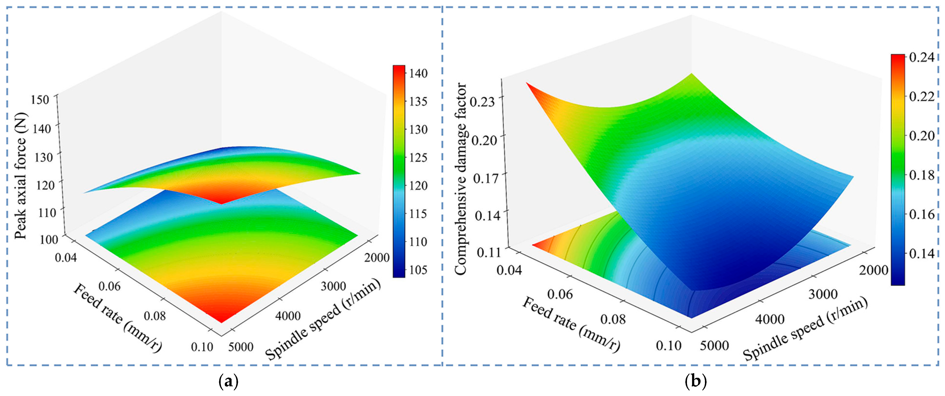
Based on the analysis results of the regression model, 3D response surface plots of the peak axial force and comprehensive damage factor with respect to the process parameters for interlaminar drilling of CFRPs are generated (Figure 12). Among them, the peak axial force exhibits a monotonic decreasing trend as the spindle speed and feed rate decrease. It reaches its minimum value at the minimum boundary of the value range for spindle speed and feed rate. For the comprehensive damage factor, it gradually decreases with the increase in feed rate, and when the feed rate exceeds 0.1 mm/r, the trend of change gradually becomes flat. During the process where the spindle speed increases from 2000 r/min to 5000 r/min, the comprehensive damage factor exhibits a variation characteristic of first decreasing and then increasing. With the optimization objective of obtaining the minimum comprehensive outlet damage factor, the optimal combination of process parameters is obtained by solving the regression model: the spindle speed is 4732.87 r/min and the feed rate is 0.137 mm/r, at which point the comprehensive exit damage factor reaches the minimum value of 0.11165.

4. Conclusions

The CFRP interlaminar drilling experiments are conducted using four different tool structures in this work. The influence of tool structure characteristics on the evolution of axial force and outlet damage is investigated. Relevant conclusions are as follows:
(1)
During the interlaminar drilling process of CFRPs, the axial force time-varying response curve is highly susceptible to the geometric structure of the tool tip. Under the same machining condition (n = 2000 r/min, f = 0.06 mm/r), the peak axial forces of the four types of drills are in the order of dagger drill (126.45 N) > candlestick drill (120.93 N) > twist drill (111.83 N) > step drill (99.62 N).
(2)
The axial force generated by the four different drills increases with the increase in feed rate. The candlestick drill is most affected by the feed rate, while the twist drill is the least. The peak axial force induced by the four different drills increases with the increase in spindle speed, but the dagger drill shows a trend of first decreasing and then increasing with the increase in spindle speed and reaches its minimum value at the spindle speed of 3000 r/min.
(3)
Under the same machining condition, the types of damage produced by the dagger drill and candlestick drill are mainly burrs and large areas of surface tear damage, respectively. But the 3D tear damage produced by twist drills and step drills is more obvious.
(4)
The comprehensive damage factor produced by twist drills is the least compared with the other tools, indicating that twist drills are more suitable for the CFRP interlaminar drilling. By constructing a mathematical prediction model for the peak axial force and comprehensive damage factor of CFRP interlaminar drilling, a process parameter optimization analysis is carried out. The optimal combination of process parameters for twist drills is a spindle speed of 4732.87 r/min and a feed rate of 0.137 mm/r.

Author Contributions

Conceptualization, Investigation, and Writing—Original Draft, P.Y.; Writing and Editing, P.Y., Q.L. and S.L.; Formal Analysis and Data Curation, Q.L.; Funding Acquisition, S.L. and P.L.; Methodology, S.L. and T.C.; Resource, S.L. and P.L.; Supervision, T.C. All authors have read and agreed to the published version of the manuscript.

Funding

This study was supported by the National Natural Science Foundation of China (No. 52475452, No. 51975208, and No. 52275423).

Data Availability Statement

The original contributions presented in this study are included in the article. Further inquiries can be directed to the corresponding author.

Conflicts of Interest

The authors declare no conflicts of interest.

References

  1. Sato, K.; Koita, T.; Inutsuka, M.; Yamaguchi, K.; Kimura, M.; Tokoro, C. Disassembly of laminated CFRP using direct pulsed discharge. Compos. Part B Eng. 2025, 297, 112301. [Google Scholar] [CrossRef]
  2. Fard, M.G.; Baseri, H.; Azami, A.; Zolfaghari, A. Prediction of delamination defects in drilling of carbon fiber reinforced polymers using a regression-based approach. Machines 2024, 12, 783. [Google Scholar] [CrossRef]
  3. Li, S.J.; Li, Q.Q.; Dai, L.Y.; Liang, W.Y.; Li, C.P.; Li, P.N.; Qiu, X.Y.; Ko, T.J. Formation mechanism of outlet damage in interlaminar drilling of CFRP. Int. J. Adv. Manuf. Technol. 2023, 129, 5117–5133. [Google Scholar] [CrossRef]
  4. Li, P.N.; Sun, J.; Li, J.; Zhang, R.Y.; Chen, G.Q. Study on drilling force and export defects of CFRP composites in RULTVD. J. Manuf. Process. 2025, 134, 880–890. [Google Scholar] [CrossRef]
  5. Seprős, S.; Markó, B.; Geier, N. Modelling of tool wear incorporating various feeds in micro-drilling of carbon fibre-reinforced polymer (CFRP) composites. Wear 2025, 574, 206086. [Google Scholar] [CrossRef]
  6. Li, Y.X.; Jiao, F.; Zhang, Z.Q.; Wang, X.; Niu, Y. Mechanical drilling force model for longitudinal ultrasonic vibration-assisted drilling of unidirectional CFRP. J. Mater. Process. Technol. 2023, 319, 118091. [Google Scholar] [CrossRef]
  7. Bi, G.J.; Wang, X.N.; Shi, Y.J.; Zhang, C.; Zhao, X.J. Numerical Investigation of the Impact of Processing Conditions on Burr Formation in Carbon Fiber-Reinforced Plastic (CFRP) Drilling with Multiscale Modeling. Materials 2025, 18, 1244. [Google Scholar] [CrossRef]
  8. Hassouna, A.; Mzali, S.; Mezlini, S.; Alrasheedi, N.H.; Hajlaoui, K. 3D micromechanical modeling of orthogonal hole saw cutting on CFRP composites. J. Thermoplast. Compos. 2024, 37, 3212–3237. [Google Scholar] [CrossRef]
  9. Xu, J.Y.; Li, C.; Mi, S.P.; An, Q.L.; Chen, M. Study of drilling-induced defects for CFRP composites using new criteria. Compos. Struct. 2018, 201, 1076–1087. [Google Scholar] [CrossRef]
  10. Qiu, X.Y.; Li, P.N.; Li, C.P.; Niu, Q.L.; Chen, A.H.; Ouyang, P.R.; Tae, J.K. Study on chisel edge drilling behavior and step drill structure on delamination in drilling CFRP. Compos. Struct. 2018, 203, 404–413. [Google Scholar] [CrossRef]
  11. Qiu, X.Y.; Li, P.N.; Niu, Q.L.; Chen, A.H.; Ouyang, P.R.; Li, C.P.; Tae, J.K. Influence of machining parameters and tool structure on cutting force and hole wall damage in drilling CFRP with stepped drills. Int. J. Adv. Manuf. Tech. 2018, 97, 857–865. [Google Scholar] [CrossRef]
  12. Jia, Z.Y.; Fu, R.; Niu, B.; Qian, B.W.; Bai, Y.; Wang, F.J. Novel drill structure for damage reduction in drilling CFRP composites. Int. J. Mach. Tool Manuf. 2016, 110, 55–65. [Google Scholar] [CrossRef]
  13. Su, F.; Chen, K.; Liu, X.; Zhang, K.; Ding, X. Research of bamboo rat tooth bionic bit structural design and cutting mechanism for CFRP drilling. Compos. Struct. 2024, 334, 117950. [Google Scholar] [CrossRef]
  14. Kim, D.; Ashrafi, S.A.; Shin, K.; Kim, T. Fiber pull-out damage formations and their effect on hole quality when drilling carbon fiber reinforced plastic (CFRP) composites using various tool geometries. Mech. Sci. Technol. 2023, 37, 4271–4280. [Google Scholar] [CrossRef]
  15. Li, S.J.; Dai, L.Y.; Li, C.P.; Chen, R.; Qiu, X.Y.; Li, P.N.; Ko, T.J. Prediction model of chisel edge thrust force and material damage mechanism for interlaminar-direction drilling of UD-CFRP composite laminates. Compos. Struct. 2022, 298, 116023. [Google Scholar] [CrossRef]
  16. Geier, N.; Szalay, T.; Takács, M. Analysis of thrust force and characteristics of uncut fibres at non-conventional oriented drilling of unidirectional carbon fibre-reinforced plastic (UD-CFRP) composite laminates. Int. J. Adv. Manuf. Technol. 2019, 100, 3139–3154. [Google Scholar] [CrossRef]
  17. Shunmugesh, K.; Panneerselvam, K. Machinability study of Carbon Fiber Reinforced Polymer in the longitudinal and transverse direction and optimization of process parameters using PSO–GSA. Eng. Sci. Technol. Int. J. 2016, 19, 1552–1563. [Google Scholar] [CrossRef]
  18. Davim, P.J.; Rubio, C.J.; Abrao, A.M. A novel approach based on digital image analysis to evaluate the delamination factor after drilling composite laminates. Compos. Sci. Technol. 2007, 67, 1939–1945. [Google Scholar] [CrossRef]
  19. Khashaba, U.A. A novel approach for characterization of delamination and burr areas in drilling FRP composites. Compos. Struct. 2022, 290, 115534. [Google Scholar] [CrossRef]
  20. Voß, R.; Henerichs, M.; Rupp, S.; Kuster, F.; Wegener, K. Evaluation of bore exit quality for fibre reinforced plastics including delamination and uncut fibres. CIRP J. Manuf. Sci. Technol. 2016, 12, 56–66. [Google Scholar] [CrossRef]
  21. Liu, L.P.; Qi, C.L.; Wu, F.; Zhang, X.F.; Zhu, X.M. Analysis of thrust force and delamination in drilling GFRP composites with candle stick drills. Int. J. Adv. Manuf. Tech. 2018, 95, 2585–2600. [Google Scholar] [CrossRef]
  22. Zhang, B.Y.; Wang, F.J.; Wang, Q.; Zhao, X. Novel fiber fracture criteria for revealing forming mechanisms of burrs and cracking at hole-exit in drilling Carbon Fiber Reinforced Plastic. J. Mater. Process. Technol. 2021, 289, 116934. [Google Scholar] [CrossRef]
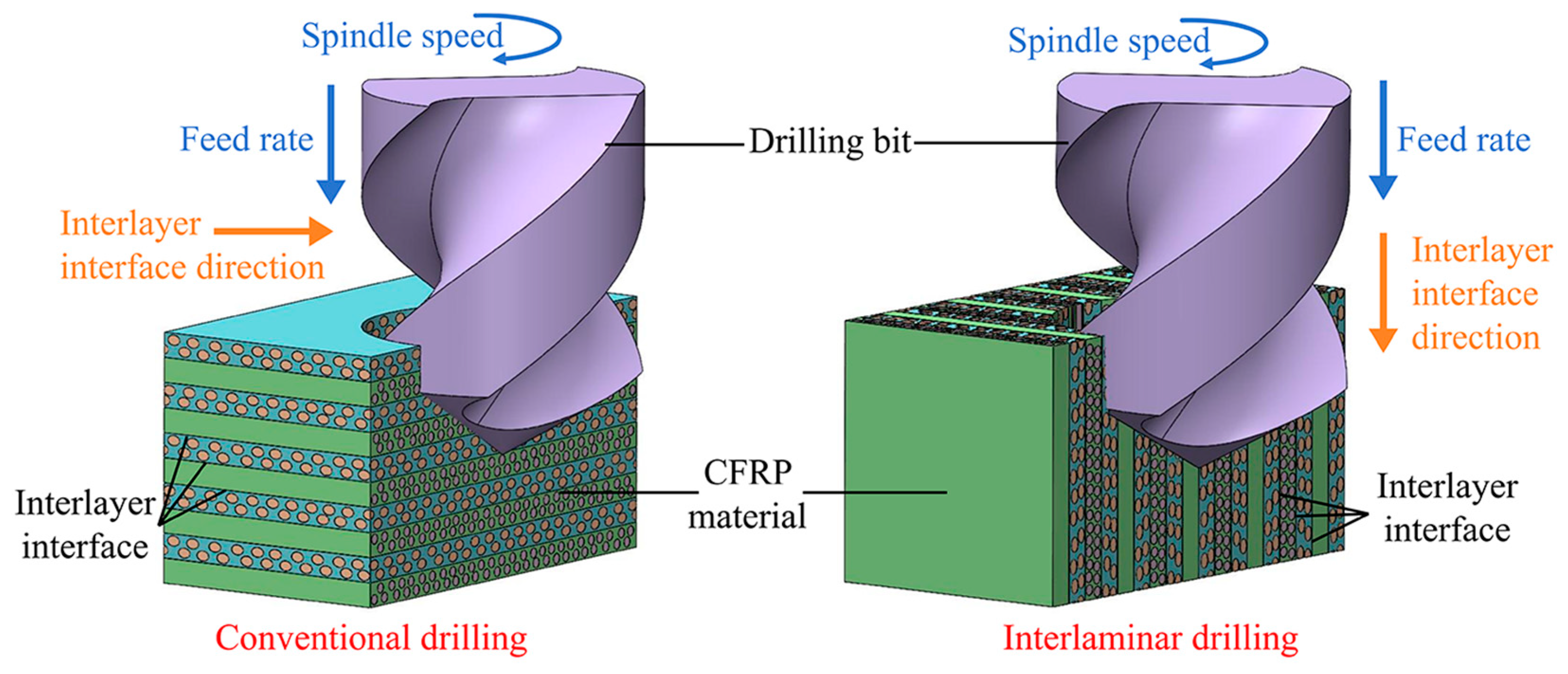
Figure 1. Schematic diagram of CFRP interlaminar drilling.
Machines 13 00919 g001
Figure 2. Experimental process: (a) CFRP curing; (b) the cross-sectional morphology of the workpiece; (c) different structural tools; (d) test scene.
Machines 13 00919 g002
Figure 3. Time-varying curve of CFRP interlaminar drilling with different drill bits (n = 2000 r/min, f = 0.06 mm/r): (a) twist drill, (b) dagger drill, (c) candlestick drill, and (d) step drill.
Machines 13 00919 g003
Figure 4. Analysis of the peak axial force in interlaminar drilling of CFRPs using different drill bits (n = 2000 r/min, f = 0.06 mm/r): (a) the peak axial force, (b) comparison of dagger drills before and after processing.
Machines 13 00919 g004
Figure 5. Relative relationship between tool feed direction and fiber laying direction.
Machines 13 00919 g005
Figure 6. Damage morphology of drilling outlet with different tool structures (n = 2000 r/min, f = 0.04 mm/r): (a) twist drill, (b) dagger drill, (c) candlestick drill, and (d) step drill.
Machines 13 00919 g006
Figure 7. Analysis of comprehensive damage factors for interlaminar drilling of CFRP materials using different structured drilling tools (n = 2000 r/min, f = 0.04 mm/r).
Machines 13 00919 g007
Figure 8. Types of damage at the outlet of CFRP interlaminar drilling.
Machines 13 00919 g008
Figure 9. Effect of different tool structures on the types of damage (n = 4000 r/min).
Machines 13 00919 g009
Figure 10. Effect of machining parameters on the peak axial force during CFRP interlaminar drilling: (a) feed rate; (b) spindle speed.
Machines 13 00919 g010
Figure 11. Effect of machining parameters on the comprehensive damage factor of outlet in CFRP interlaminar drilling: (a) feed rate; (b) spindle speed.
Machines 13 00919 g011
Figure 12. The 3D response surface diagram of CFRP interlaminar drilling: (a) peak axial force; (b) comprehensive damage factor.
Machines 13 00919 g012
Table 1. Performance parameters of CFRPs.
ParameterValue
Fiber volume fraction, Vf (%)60
Poisson’s ratio, vf0.25
Longitudinal Young’s modulus, Ex (GPa)230
Lateral Young’s modulus, Ey (GPa)15
Longitudinal tensile strength, Xt (MPa)1347
Lateral tensile strength, Yt (MPa)68.9
Longitudinal compressive strength, Xc (MPa)1277
Lateral compressive strength, Yc (MPa)112
Table 2. Experimental parameter settings for CFRP interlaminar drilling.
NumberSpindle Speed
(r/min)
Feed Rate
(mm/r)
Cutting Speed
(m/min)
Feed per Tooth
(mm/z)
120000.040.080.02
220000.060.120.03
320000.080.160.04
420000.100.200.05
530000.040.120.02
630000.060.180.03
730000.080.240.04
830000.100.300.05
940000.040.160.02
1040000.060.240.03
1140000.080.320.04
1240000.100.400.05
1350000.040.200.02
1450000.060.300.03
1550000.080.400.04
1650000.100.500.05
Table 3. Experimental results of CFRP interlaminar drilling (twist drill).
NumberSpindle Speed
(r/min)
Feed Rate
(mm/r)
Peak Axial Force (N)Comprehensive Damage Factor
120000.04101.90.19588
220000.06111.830.1802
320000.08118.380.16662
420000.10125.860.16642
530000.04111.430.22425
630000.06122.840.16715
730000.08124.430.15261
830000.10128.120.12791
940000.04113.120.17691
1040000.06123.610.14768
1140000.08131.510.14302
1240000.10134.210.14053
1350000.04112.860.25629
1450000.06128.730.19158
1550000.08136.050.17579
1650000.10143.20.11707
Table 4. Significance analysis of the peak axial force model in CFRP interlaminar drilling.
ParameterSum of SquaresDegree of FreedomMean Square ValueFpEvaluate
Model1710.45135342.09025855.8362370.000001Significant
n13.2497113.2497462.1626340.172154
f74.5601174.56005512.169750.005837
n26.838216.8382251.116140.315605
nf15.6975115.6974742.5621540.140532
f244.4890144.4889517.2615210.022516
Residual error61.2667106.126671
Total variance1771.718015
Table 5. Significance analysis of a comprehensive damage factor model for CFRP interlaminar drilling.
ParameterSum of SquaresDegree of FreedomMean Square ValueFpEvaluate
Model0.015250.0030378.627940.002144Significant
n0.000610.0005711.6211820.231728
f0.000310.0002650.7539540.405584
n20.001810.0018025.1184460.047176
nf0.001610.0016194.5988870.057596
f20.000410.0004061.1536970.30801
Residual error0.0035100.000352
Total variance0.018715
Table 6. Coefficient analysis of peak axial force model for drilling.
ParameterValue
Standard deviation10.8681
Average value123.0050
Coefficient of variation0.0884
Coefficient R20.9654
Adjust R20.9481
Predict R20.7830
Signal-to-noise ratio14.4589
Table 7. Coefficient analysis a of comprehensive damage factor model for CFRP interlaminar drilling.
ParameterValue
Standard deviation0.0353
Average value0.1706
Coefficient of variation0.2070
Coefficient R20.8118
Adjust R20.7177
Predict R20.3509
Signal-to-noise ratio6.3488
Disclaimer/Publisher’s Note: The statements, opinions and data contained in all publications are solely those of the individual author(s) and contributor(s) and not of MDPI and/or the editor(s). MDPI and/or the editor(s) disclaim responsibility for any injury to people or property resulting from any ideas, methods, instructions or products referred to in the content.