1. Introduction
The rapid transition toward electric vehicles (EVs) has brought unprecedented challenges and opportunities to automotive engineering. In internal combustion engine (ICE)-powered vehicles, engine and drivetrain vibrations often govern the design of suspension mounts and vibration isolation systems. However, in EVs, the absence of significant engine-induced excitation alters the dynamic environment of the suspension system. Instead, road-induced excitations transmitted through the tires and chassis are the primary contributors to vibration and acoustic discomfort. This paradigm shift necessitates a reevaluation of the fundamental design concepts for suspension mounts in EVs. Although conventional parallel-type mount configurations, in which the spring and damper elements act in parallel, are widely used in passenger vehicles, their performance is optimized under the assumption of mixed excitation sources, including engine vibrations. Therefore, the conventional design may be suboptimal for EV-specific requirements, particularly for isolating road-induced vibrations and enhancing ride comfort in the low-to-mid-frequency range.
Vibration isolation in EV suspension systems is directly related to ride comfort and structural durability. Road-induced vibrations not only reduce passenger comfort but also accelerate the fatigue damage of structural and electronic components, including battery packs, inverters, and electronic control units. Furthermore, EVs tend to have higher unsprung masses owing to the increased weight of the battery modules and electric drive units, making them more susceptible to vibration amplification in specific frequency bands. Recent studies have emphasized that effective vibration isolation in the frequency range below 100 Hz is critical because this range coincides with the dominant excitation frequencies from road irregularities. Furthermore, secondary vibration peaks often occur because of the interaction between suspension elements and auxiliary isolation components such as bushings and pads, which can result in undesirable resonance phenomena. Therefore, both simulation-based optimization and experimental verification are essential for accurately capturing and mitigating these dynamic effects.
Vehicle-suspension systems play a pivotal role in ensuring ride comfort, road holding, and handling stability; however, their design remains a fundamental challenge in automotive engineering. Studies on heavy road vehicles have highlighted the inherent tradeoffs among vertical comfort, suspension working space, energy consumption, and rollover or yaw stability [
1]. Researchers have proposed structural modifications and advanced control strategies to address these issues. Comparative analyses have emphasized that while conventional parallel-type suspension mounts provide robustness, their ability to isolate road-induced vibrations is limited, particularly in modern EVs, where frame-induced excitations are significantly reduced [
2].
Considerable effort has been expended to develop alternative suspension concepts, such as a hydraulically interconnected suspension (HIS). This type of system enables independent tuning of the bounce, roll, pitch, and warp modes through hydraulic circuits, leading to improved rollover resistance and ride-handling balance [
3,
4,
5]. Similarly, optimization-based approaches have been extensively adopted, where evolutionary algorithms or particle swarm optimization have been applied to tune the suspension stiffness and damping to improve the ride comfort, tire grip, and working space [
6,
7,
8]. Parameter identification techniques further support accurate vehicle modeling by combining kinematics and compliance testing with multibody simulations [
9].
In parallel with the suspension design, vehicle-level studies have addressed the integration of suspension parameters with the stability and handling performance. Investigations using three-dimensional models, finite-element simulations, and flexible multibody approaches have revealed that the suspension characteristics strongly affect the vehicle yaw stability, tire contact, and comfort indices [
10,
11,
12]. These studies underline the necessity of considering the road excitation spectra, slip angle effects, and structural flexibility when evaluating new suspension layouts. Another dominant research stream involves active and semi-active suspension control. Approaches using preview control, intelligent algorithms, and magnetorheological (MR) dampers have shown significant improvements in vibration isolation, body acceleration reduction, and rollover mitigation [
13,
14,
15,
16]. Recent studies have proposed specialized active-suspension strategies for EVs [
17,
18,
19] and fault-tolerant control methods for active-suspension systems [
20], highlighting the ongoing intensive research in this field. Although these systems demonstrate superior performances, their reliance on actuators, sensors, and external energy inputs introduces high cost and complexity, limiting their practical adoption in EV platforms.
In contrast, purely passive suspension solutions continue to attract attention because of their simplicity, reliability, and zero energy consumption. Advances include the use of inerters to enhance the phase and impedance properties, novel shock absorbers with a variable moment of inertia, and meta-heuristic optimization methods for spring–damper tuning [
21,
22,
23]. Although these designs provide notable benefits, they often require additional mechanical devices or rely solely on parameter optimization, leaving structural reconfiguration largely unexplored.
Despite the breadth of prior research on suspension design, active and semi-active control, and the optimization of passive systems [
1,
2,
3,
4,
5,
6,
7,
8,
9,
10,
11,
12,
13,
14,
15,
16,
17,
18,
19,
20,
21,
22,
23], few studies have explored the potential of structurally reconfiguring the mount architecture. Most investigations have remained confined to conventional parallel spring-damper layouts, relying either on advanced control algorithms or auxiliary elements such as inerters, MR dampers, and variable inertia absorbers. In contrast, the present study adopts a fundamentally different perspective by structurally reconfiguring a conventional suspension mount from a parallel spring–damper layout to a novel series-type arrangement. This straightforward yet effective modification eliminates the need for actuators or complex auxiliary mechanisms, while still delivering vibration isolation performance tailored for EVs. By introducing this structural shift, the series-type configuration provides an additional degree of freedom that decouples vibration transmission, thereby achieving superior transmissibility characteristics through a purely passive solution. The originality of this work lies not only in demonstrating the feasibility of such a simplified yet high-performing architecture but also in systematically extending the formulation to incorporate auxiliary sub-mount elements. Both simulations and experimental validation confirmed that the stiffness of these sub-mount components plays a decisive role in shaping the transmissibility curves, inducing secondary resonance peaks, and ultimately governing the overall isolation performance. While this investigation remains at the proof-of-concept stage and does not attempt to integrate semi-active or active suspension strategies into the proposed layout, the fundamental structural concept is independent of vehicle payload and could be applied across both light-duty and heavy-duty platforms. Collectively, these findings bridge the gap between theoretical modeling and practical implementation and provide concrete design guidelines for the development of next-generation EV suspension systems that are efficient, robust, and industry-ready.
It should be noted that the present study was conducted as a proof of concept, and therefore several limitations must be acknowledged. First, the suspension models employed were simplified representations that did not fully capture the complexity of real vehicle systems. Thus, their direct applicability to actual EV platforms requires further validation. Second, the current analysis was confined to vibration transmissibility characteristics without addressing other critical suspension objectives, such as ride comfort, handling stability, and overall vehicle dynamics. Third, the loading conditions used in the modeling and experiments represented idealized inputs rather than realistic road excitations. Finally, the experimental validation was performed using a simplified specimen that did not replicate the full structural complexity of a real suspension system. These limitations were inherent in the scope of this investigation, which aimed to establish the feasibility of a structurally reconfigured series-type mount concept. Future work will extend this foundation to vehicle-level modeling, broader performance metrics, and experimental validation under realistic operating conditions.
The remainder of this paper is organized as follows.
Section 2 formulates the theoretical models for both parallel- and series-type suspension configurations and derives the governing equations for vibration transmissibility.
Section 3 presents the simulation setup and the results of a comparative analysis of the two mount types, including the extended series-type configuration.
Section 4 describes the design and fabrication of the prototype specimen, details the experimental procedure using impact-hammer excitation, and discusses the experimental findings with particular emphasis on the isolation performance and the emergence of resonance peaks linked to the sub-mount components. Finally,
Section 5 concludes the paper by summarizing the key contributions, highlighting the originality of the proposed concept for EV suspension design, and outlining future research directions.
2. Transmissibility of the Basic Quarter-Car Model
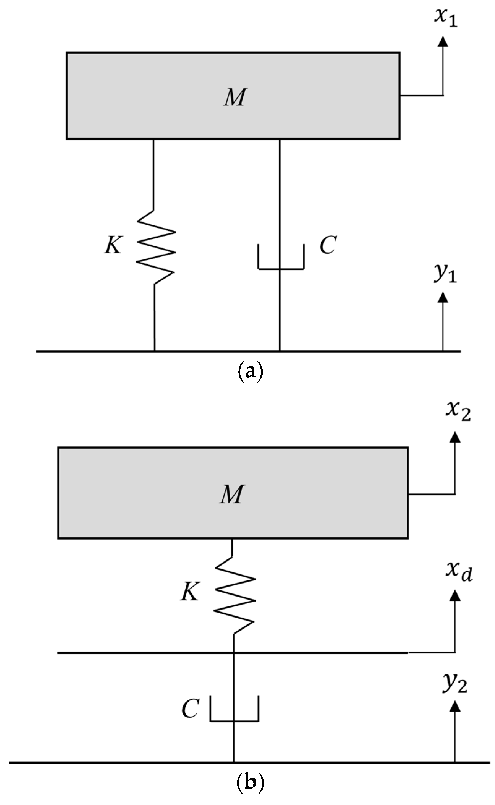
In conventional internal combustion engine (ICE) vehicles, the suspension system typically features integrated springs and dampers mounted beneath the chassis. Hence, the suspension was modeled with a parallel configuration for these springs and dampers. In contrast, the proposed mount module arranged the springs and dampers in series, forming the basis of a new vehicle model. To evaluate the characteristics of these automotive suspension systems, it was necessary to construct vehicle models that included them. This made it possible to assess the desired dynamic response under various suspension configurations. Because the primary focus of this study was the suspension rather than the entire vehicle, each suspension system was modeled using fundamental linear mechanical components: a spring (
) and damper (
). The upper part of the suspension, which represented the vehicle body, was simplified as a lumped mass (
). Assuming that the motion of the suspension system was confined to the vertical direction, the behavior of the lumped mass representing the upper vehicle body was expressed by a single degree of freedom variable (
), whereas the excitation input from the road surface was represented by a separate variable (
). Variable
was the displacement of the node between the spring and damper. The simplified quarter-car models for the different suspension configurations are shown in
Figure 1.
A quarter-car model with a parallel-type suspension module (
Figure 1a) can be formulated using Equation (1).
The quarter-car model with a series-type suspension module (
Figure 1b), which is the proposed model for an EV, can be formulated using Equations (2) and (3).
The dynamics of the mechanical system can be represented by the frequency response function or transmissibility, and the two previous quarter-car models can be used to determine the transmissibility by assigning the input variables (
and
) and response variables (
and
) for each quarter-car model. The Laplace transform of the governing equation was preliminarily used to derive the ratio of the response and input of each simple model, assuming zero initial displacement and velocity. Equation (1) can be transformed into the s domain, as shown in Equation (4).
The second model has three variables (
,
, and
), and the transmissibility between input
and output
can be found by combining Equations (2) and (3), as follows.
The s-domain formulation can be transformed into the frequency domain (
) by inserting
, and the transmissibility for two quarter-car models can be represented by Equations (6) and (7).
In
Figure 1b, the present series-type suspension module is modeled as a lumped mass–stiffness–damper system. An alternative formulation, in which the elements are arranged as a lumped mass–damper–stiffness, was also considered and found to produce the same transmissibility expression as Equation (7). This equivalence confirmed that the current model was sufficient to represent both configurations. Furthermore, the sprung mass representing the equivalent wheel mass in the quarter-car model [
24,
25] was not included in this study to minimize the number of effective system parameters, except for the subcomponents of the suspension module. Under the same normalized input conditions (
and
) for transmissibility, the two simplified quarter-car models focused on the suspension-module configurations.
The quarter-car models were simulated using two different types of suspension mechanisms, and the basic parameters of the simulation models are summarized below. All of the system parameters for the quarter-car models were selected from previous studies, as summarized in
Table 1 [
24,
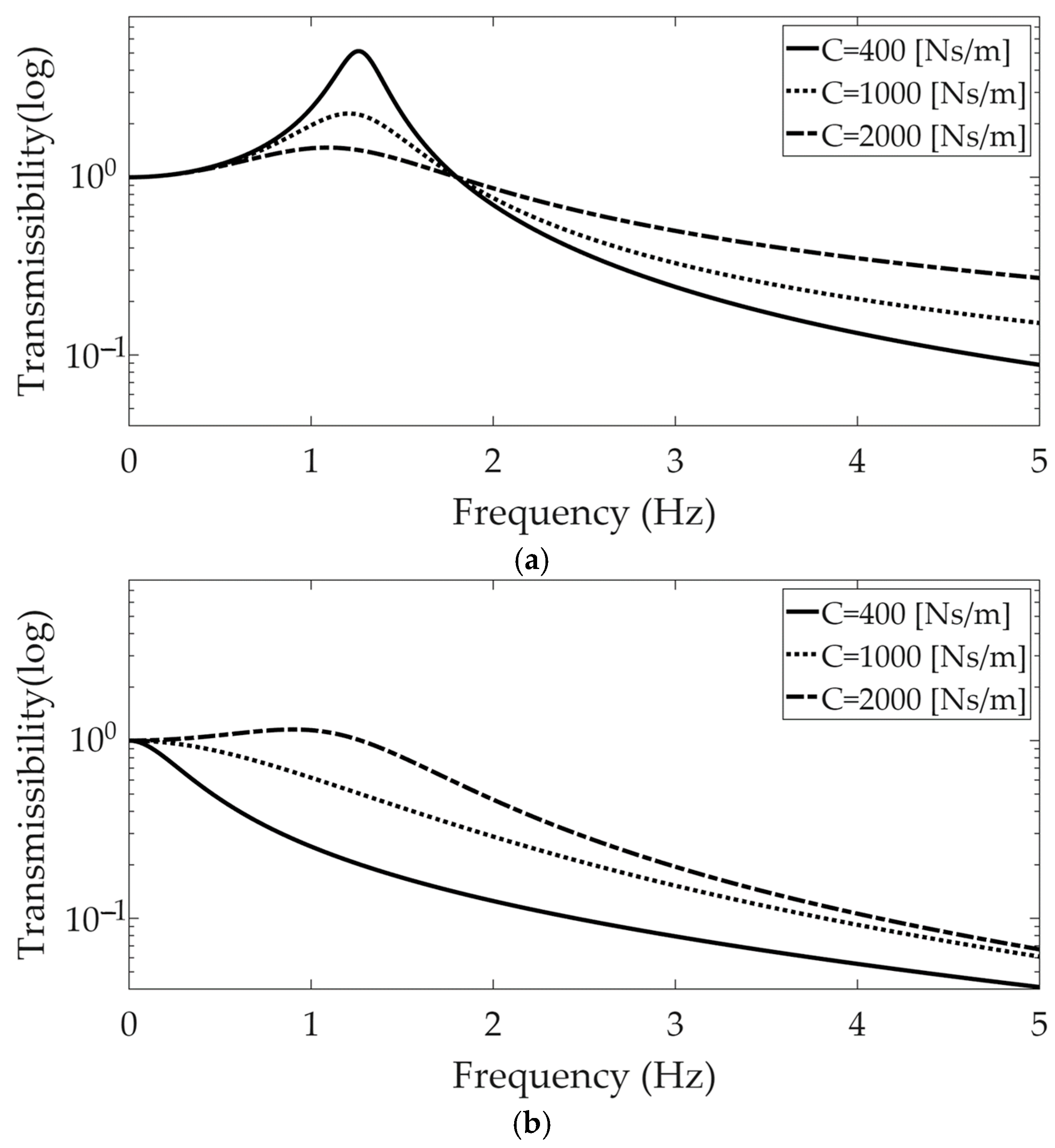
25]. The fundamental frequency was approximately 1.27 (Hz) with a spring coefficient of 16,000 (N/m) under the no-damping condition, and the critical damping coefficient was calculated to be 4000 (Ns/m) at the same stiffness value. The modal damping ratios were 0.1, 0.25, and 0.5, based on the three damping coefficients, 400 (Ns/m), 1000 (Ns/m), and 2000 (Ns/m), respectively.
The simulation results for the two different types of suspension are shown in
Figure 2 for the three damping coefficients. The conventional parallel-type suspension module showed a peak value near the resonance frequency; thus, this suspension module was susceptible to basement excitation near the resonance frequency. In the high-frequency range, all of the responses of the vehicle part decreased for all of the damping coefficient values. In the near-resonance frequency range, the transmissibility was amplified by decreasing the damping coefficient value; however, the transmissibility was less than one, which increased with the damping coefficient in the high-frequency range. These results were the opposite to those obtained in the low-frequency range. In contrast, the transmissibility was less than one for damping coefficients of 400 (Ns/m) and 1000 (Ns/m), but became greater than one near the resonance frequency at a damping coefficient of 2000 (Ns/m). Therefore, the transmissibility increased with the damping coefficient.
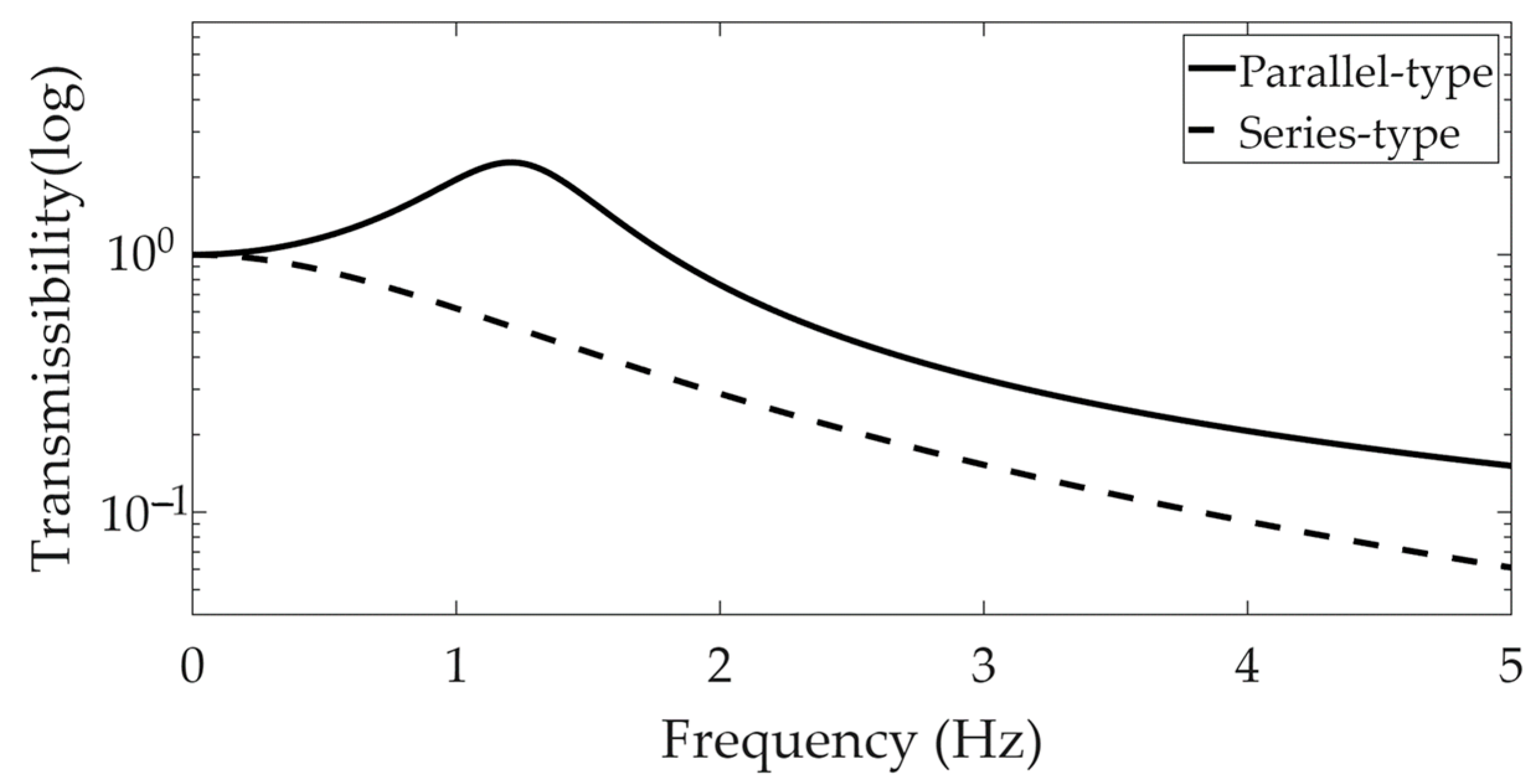
A comparison of the two types of suspension modules was performed for the same damping coefficient of 1000 (Ns/m). The more rapid reduction in transmissibility provided greater benefits for the series-type suspension than for the parallel-type suspension, as illustrated in
Figure 3.
The simulation results demonstrated the high performance of the series-type suspension module compared to the parallel-type suspension module in a quarter-car model. When examining the performance of the vehicle suspension module, this study focused on the basement excitation case, and the conventional vehicle suspension was particularly susceptible to the frequency range near the resonance region.
3. Transmissibility of a Quarter-Car Model with an Extended Series-Type Suspension Module
The theoretical quarter-car model comprised a simplified suspension module; therefore, it was not sufficient to represent the dynamic responses of a quarter-car system with this approximated suspension. Thus, it was desirable to extend this simple structure, which included a single stiffness and single damper in series, by inserting additional mechanical components to account for the multiple mechanical characteristics found in the field. The equivalent modeling of the mechanical systems with a supporting mount module was previously studied using a similar modeling process, and the accuracy of the theoretical modeling can be successively proven with test results using the multiple-degree-of-freedom mount module structure [
26,
27,
28]. Because the mechanical damper or stiffness component did not adequately represent a single stiffness or damping coefficient, an extended version of the series-type vehicle suspension was considered in this step using a similar method. The basic quarter-car model was the same as that shown in
Figure 1, where
is the vehicle body mass and the mechanical coefficients of the spring and damper are
and
, respectively. The extended mechanical elements of the spring and damper coefficients are
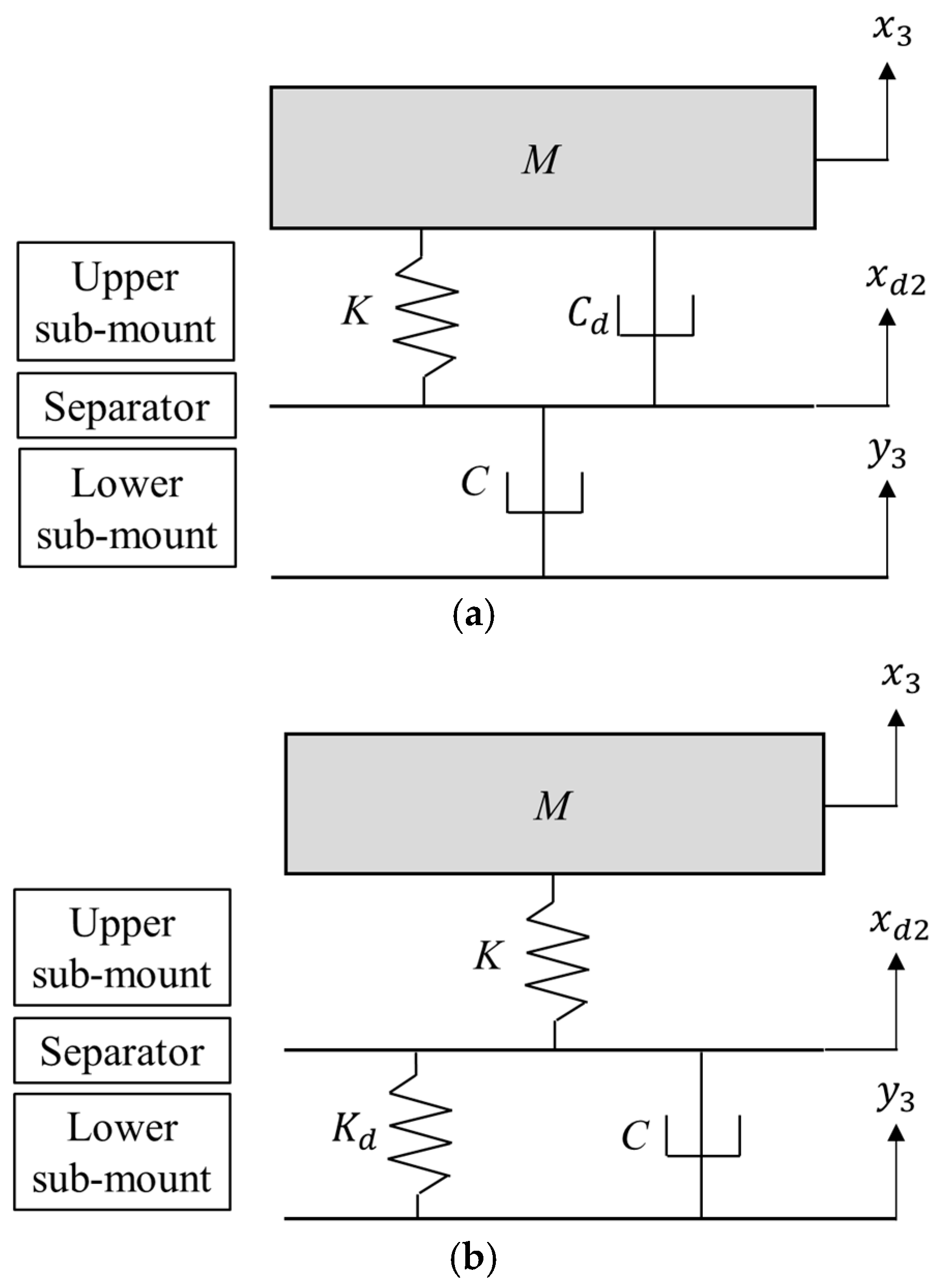
and
, respectively. The extended series-type mount device comprises two parts: an upper sub-mount near the supporting mass (
) and a lower sub-mount beneath the separator, as illustrated in
Figure 4. In addition, the response variables of the quarter-car model were defined as
,
, and
for the upper vehicle body, road input, and separator between the upper and lower mounts, respectively. Two extended-series-type quarter-car models are shown in
Figure 4.
The quarter-car model with the extended series-type I suspension was formulated using Equations (8) and (9).
For the extended series-type I suspension module, the transmissibility is defined between the basement input (
) and vehicle response (
), with the intermediate variable
excluded from consideration. From governing Equations (8) and (9), this transmissibility is subsequently derived and reformulated in the Laplace domain, as presented in Equation (10).
The governing equations for the quarter-car model with the extended-series type II module are formulated as Equations (11) and (12).
The transmissibility between the basement input (
) and vehicle response (
) is also calculated using Equations (11) and (12) and simplified using Equation (13) in the Laplace transform as follows.
The transmissibility values of the two types of extended series suspension modules can be transformed to the frequency domain with
, and the resulting values are defined as
and
for suspension types I and II, respectively, as shown below.
Both transmissibility functions characterize the vibration transmission from the road input to the upper vehicle body such that the spectral magnitude at each frequency reflects the corresponding vibration isolation performance. Accordingly, the objective is to minimize the transmissibility within the frequency range of interest, as defined by Equations (14) and (15).
The basic model parameters for the quarter-car model are the same as the previous model parameters listed in
Table 1, where
,
, and
, as summarized in
Table 2. The newly introduced parameters were selected considering the basic stiffness or damping coefficient; the
values for type I were set at 10%, 50%, and 100% of
, and the
values for type II were set at 10%, 50%, and 100% of
. Both parameters were introduced to represent the dual characteristics of the sub-mounts in an extended series-type suspension module.
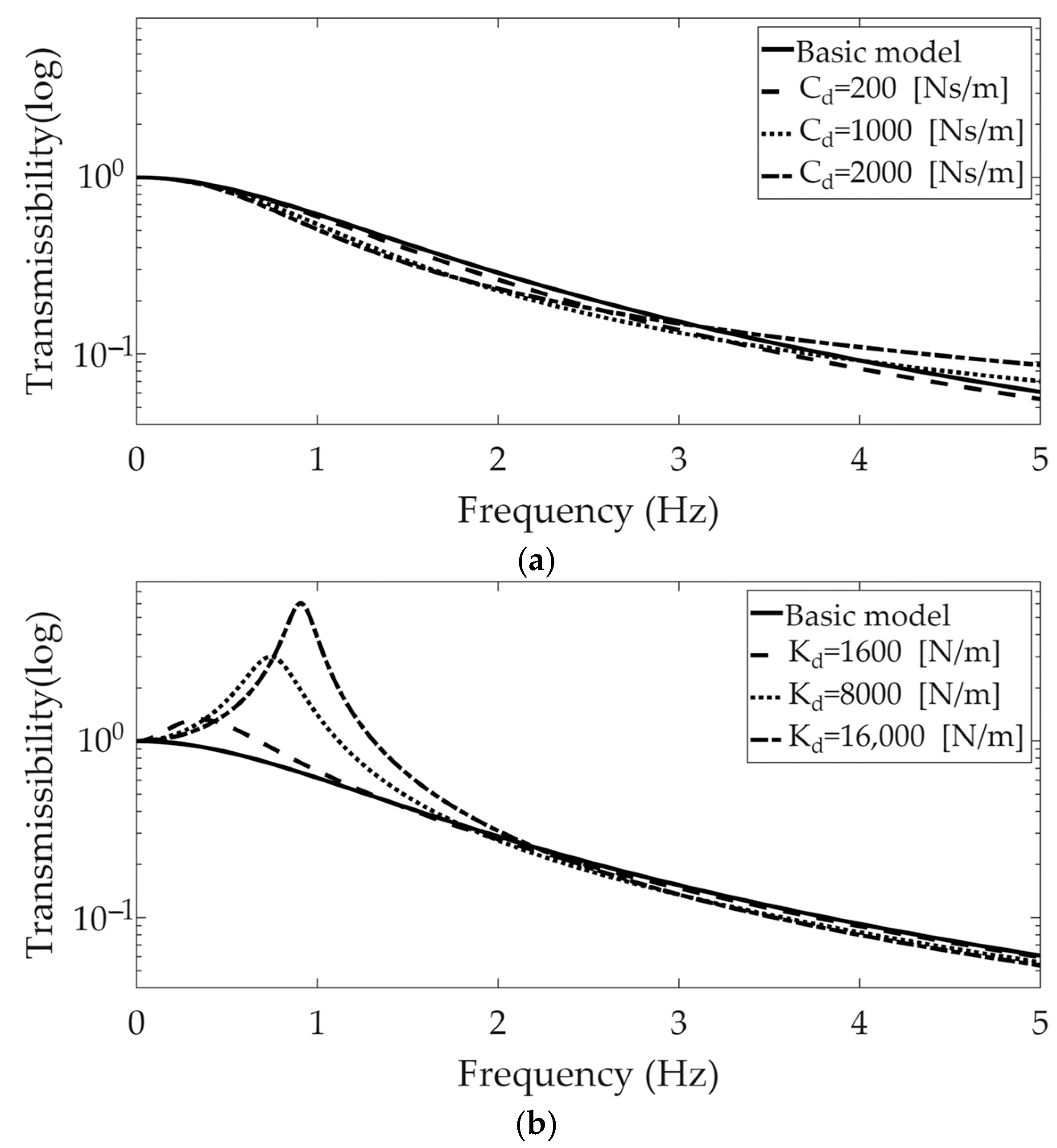
Simulation results for the two types of suspension modules were obtained for the selected values of the additional mechanical coefficients (
and
) and are plotted in
Figure 5.
The additional damping coefficient, , was not effective in altering the transmissibility of the basic model. It had a value of one at a frequency of 0 (Hz) and decreased rapidly as the frequency increased. In contrast, a peak value was found near 0.3 (Hz) with , and both the peak value and corresponding frequency increased when . This implied that the effect of the additional stiffness coefficient, , was considerable in the series-type suspension module, decreasing the isolation capability of the suspension module over the basement input.
4. Experimental Validation with Simple Structure
The extended series-type suspension module was validated using a simple rectangular structure (80 mm (W) × 150 mm (L) × 3 mm (H)) that supported the suspension module. This simple isotropic structure was made of 304SS, and its dynamic characteristics could be represented by modal parameters, which were measured in previous studies [
29]. The modal parameters were obtained through an experimental modal test procedure using a simple rectangular structure [
30,
31]. The first resonance frequency was 647.2 (Hz), which allowed it to be a rigid body if the frequency of interest was less than 100 (Hz). The mass of the simple rectangular structure was 285 (g).
The suspension device for the experimental simple structure was prepared with both a general coil-spring and a vibration isolation pad, which was a commercial product (model: Sylodamp
® SP10) from Getzner company (Bludenz, Austria) with a loss factor of 0.61, a maximum static load of 0.005 (N/mm
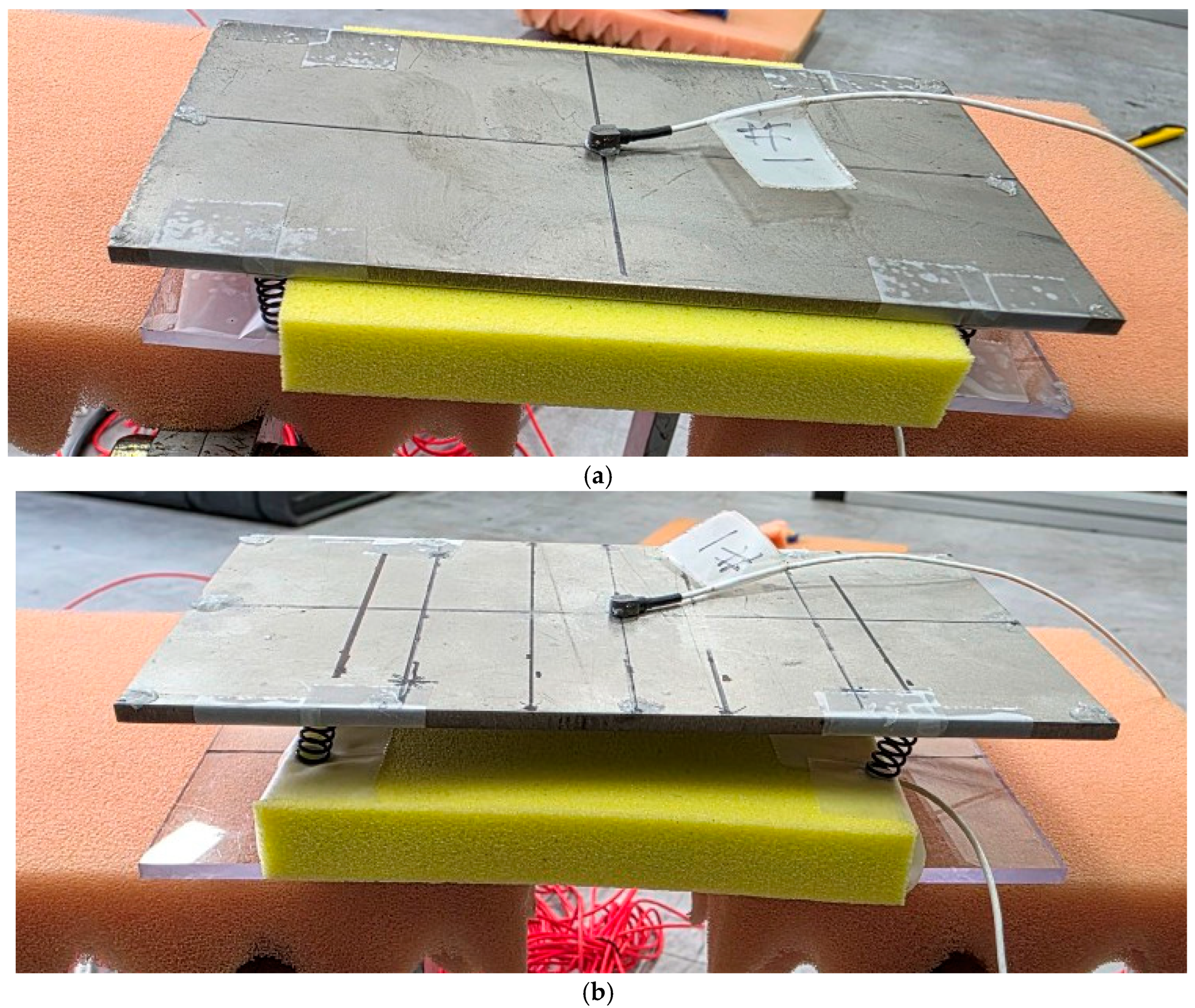
2), and a coefficient of restitution of 13%. Using two physical-mechanical subcomponents, two supporting suspension modules ((a) series and (b) parallel) were prepared, as illustrated in
Figure 6. Four coil springs were placed in a manner to distribute the weight evenly to allow vertical motion of the supporting simple structure without coupled rotational motion.
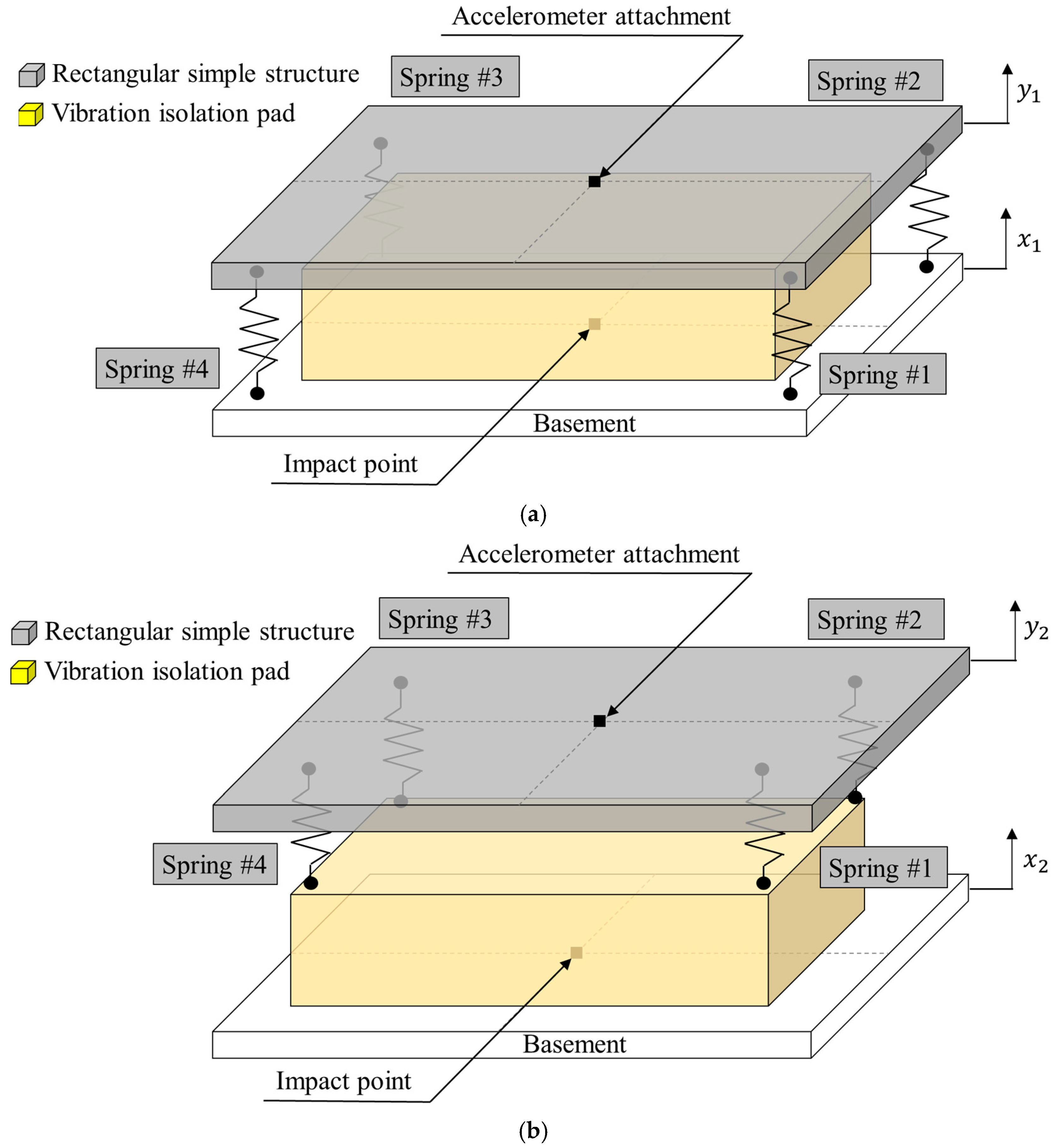
The two test setups for the simple structure can be simplified with mechanical elements, including four springs and a vibration isolation pad, and these configurations are illustrated in
Figure 7. The simple structure moved in the vertical direction. Thus, the supporting structure could be integrated with two equivalent mechanical elements: a single spring and single damper.
The prepared test setup was designed with a symmetric configuration by placing four coil springs at evenly distributed locations, along with a vibration isolation pad attached to the middle of the basement structure. Therefore, the supporting structure could only respond in the vertical direction if a force was applied at the center of the test specimen. The excitation force was applied to the middle of the basement using an impact hammer (model 5800B3; Dytran, Chatsworth, CA, USA), and the acceleration response was recorded at the center of the simple rectangular structure using a lightweight accelerometer (model 3225F2; Dytran, Chatsworth, CA, USA), as shown in
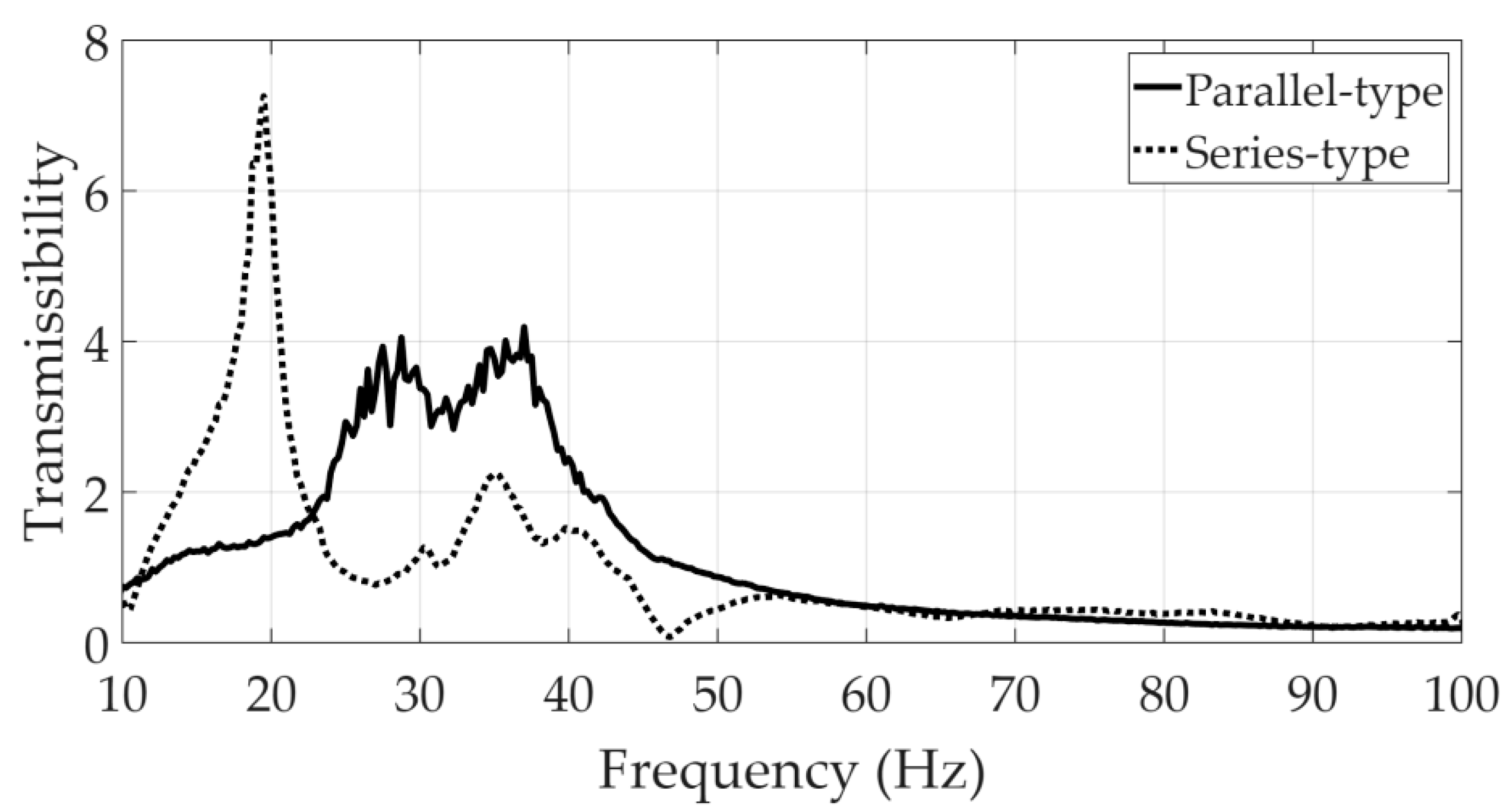
Figure 7, to prevent a mass loading effect from the attached accelerometer. All measured data and the frequency response function between the force and acceleration were obtained using Test.Lab software (15A version, Siemens, Munich, Germany). The acceleration spectrum at the center of the simple rectangular structure was divided by the acceleration spectrum at the center of the basement, and the resulting function was equivalent to the transmissibility, which was an indicator of the vibration isolation capability of the suspension module. The transmissibility function is illustrated in
Figure 8.
The transmissibility from the parallel-type suspension had relatively high values between 30 (Hz) and 40 (Hz), but its value decreased as the frequency increased to 100 (Hz). The vibration isolation was effective at frequencies greater than 50 (Hz) owing to the transmissibility value being less than one. In contrast, the transmissibility with the series-type suspension was smaller than that with the parallel-type suspension at a frequency range of less than 50 (Hz) except for the peak value near 20 (Hz). The transmissibility values for the two cases were similar at frequencies greater than 50 (Hz). The major trends for the two transmissibility curves were similar, as illustrated in
Figure 2, but the peak value found near 20 (Hz) can be understood from the simple model discussed in
Section 3. The unexpected transmissibility peak near 20 (Hz) with the series-type suspension module can be interpreted using the simulation case of the quarter-car model with an extended series-type suspension module, considering the effect of additional spring elements. Because the additional spring element (
) played a critical role in the initiation of the peak in the transmissibility with the series-type suspension module, the observed peak near 20 (Hz) may be attributed to the effect of the spring behavior in the vibration isolation pad in the test case.
It should be emphasized that the experimental validation conducted in this study was limited to a simplified specimen consisting of a rectangular plate, coil springs, and a commercial isolation pad. Consequently, the measured frequency characteristics, particularly within the 10–100 Hz range, reflected the specific conditions of this test configuration, rather than the full operational spectrum of an actual EV suspension system. In practice, lower-frequency dynamics below 10 Hz are known to play a critical role in ride comfort and vehicle handling. However, capturing such effects was beyond the scope of the present proof-of-concept setup. Despite these limitations, our experimental results make two important contributions to literature. First, they clearly demonstrated that the proposed series-type suspension mount exhibited a superior vibration isolation performance compared with that of the conventional parallel configuration, even under simplified testing conditions. Second, the results confirmed that the mechanical properties of the auxiliary sub-mount elements, particularly the stiffness, directly shaped the transmissibility curves and induced a secondary resonance behavior, thereby offering valuable insights into suspension design parameters. These findings validate the fundamental advantages of the series-type concept and highlight its potential as a practical basis for developing EV-oriented suspensions.
It should also be acknowledged that the proposed series-type mount, while effective in reducing road-induced vibrations, may introduce packaging challenges when applied to real EV platforms. Specifically, the reconfiguration of the spring and damper elements into a series arrangement could require additional vertical or longitudinal space, which may pose difficulties in vehicle integration. Because this study was conducted as a proof of concept, detailed structural design and potential modifications to the vehicle architecture were beyond the scope of this study. Therefore, future research should address these practical constraints through optimized suspension geometries or vehicle-level design adaptations to ensure feasibility and performance in real-world applications.
5. Conclusions
This study evaluated a novel series-type suspension mount specifically designed for EV applications. Unlike conventional parallel-type mounts, the series arrangement of the spring and damper demonstrated the distinct ability to attenuate road-induced vibrations in both simulations and experimental verification. A comparative analysis of quarter-car models confirmed that the series-type configuration achieved a faster reduction in transmissibility across a wide frequency range, thereby enhancing the vibration isolation performance.
An extended series-type model was developed to incorporate additional springs and dampers, thereby providing a framework for interpreting the influence of auxiliary sub-mount elements. The simulation results revealed that, while damping variations had limited effects, the sub-mount stiffness played a decisive role in shaping the transmissibility curves and inducing secondary resonance peaks. These findings were consistent with the experimental observations, where a resonance near 20 Hz was attributed to the inherent spring behavior of the isolation pad. The test setup and impact-hammer testing of the prototype confirmed the practical feasibility of the proposed concept. The experimental results demonstrated superior vibration isolation up to 100 Hz, validating the effectiveness of the series-type mount under realistic excitation conditions.
In summary, the originality of this work lies in demonstrating that a structural reconfiguration alone, without relying on additional mechanical components such as inerters or costly active devices, can deliver substantial improvements in vibration isolation. This proof of concept highlights a passive yet efficient solution that is simple and practical for EV platforms. Furthermore, the results provide (1) clear evidence that the proposed series-type mount can directly mitigate road-induced vibrations, which dominate the EV driving environment; (2) practical insights into the role of an auxiliary sub-mount stiffness element in managing resonance phenomena; and (3) a new design paradigm that addresses real-world EV challenges, such as ride quality, passenger comfort, and the protection of sensitive components.
