Abstract
This paper proposes an enhanced Model Predictive Direct Speed Control (MPDSC) framework for Permanent Magnet Synchronous Motor (PMSM) drives, integrating duty ratio optimization and load torque disturbance compensation to significantly improve both transient and steady-state performance. Traditional finite-control-set MPC strategies, which apply a single voltage vector per sampling interval, often suffer from steady-state ripples, elevated total harmonic distortion (THD), and high computational complexity due to exhaustive switching evaluations. The proposed approach addresses these limitations through a novel dual-stage cost function structure: the first cost function optimizes dynamic response via predictive control of speed error, while the second adaptively minimizes torque ripple and harmonic distortion by adjusting the active–zero voltage vector duty ratio without the need for manual weight tuning. Robustness against time-varying disturbances is further enhanced by integrating a real-time load torque observer into the control loop. The scheme is validated through both MATLAB/Simulink R2020a simulations and real-time experimental testing on a dSPACE 1202 rapid control prototyping platform across small- and large-scale PMSM configurations. Experimental results confirm that the proposed controller achieves a transient speed deviation of just 0.004%, a steady-state ripple of 0.01 rpm, and torque ripple as low as 0.0124 Nm, with THD reduced to approximately 5.5%. The duty ratio-based predictive modulation ensures faster settling time, improved current quality, and greater immunity to load torque disturbances compared to recent duty-ratio MPC implementations. These findings highlight the proposed DR-MPDSC as a computationally efficient and experimentally validated solution for next-generation PMSM drive systems in automotive and industrial domains.
1. Introduction
Model Predictive Control (MPC) has emerged as a powerful control methodology in modern power electronics, particularly for high-performance applications such as Permanent Magnet Synchronous Motor (PMSM) drives [1,2,3]. Among its many variants, Model Predictive Direct Speed Control (MPDSC) has gained prominence for its ability to directly regulate motor speed while accommodating system constraints [4,5], offering advantages over traditional methods like Field-Oriented Control (FOC) [6,7,8] and Direct Torque Control (DTC) [9,10,11]. Unlike classical cascaded controllers, MPDSC predicts future motor behavior over a finite horizon and selects optimal control actions that minimize a predefined cost function, enabling fast dynamic response and improved disturbance rejection [12,13]. Despite these benefits, real-time implementation of MPDSC remains challenging due to its computational complexity, especially at fast sampling rates [14,15]. To address this, various efforts have been made to reduce the processing burden through simplified predictive models, efficient optimization routines, and reduced-order systems. Furthermore, constrained MPDSC has been introduced to account for voltage and current limitations, ensuring safe operation under practical conditions [16,17,18]. Hybrid MPC frameworks that incorporate fuzzy logic, sliding-mode control, or neural networks have also been investigated to enhance robustness and reduce dependency on system modeling accuracy [19,20,21]. A key concern in high-performance PMSM drives is the presence of unknown or varied load torque disturbances, which adversely affect speed stability and torque smoothness [22]. Consequently, modern MPDSC strategies often include real-time load torque estimation and compensation techniques, such as Kalman filters or observer-based methods, to enhance dynamic accuracy [23,24,25]. Recent research has also expanded toward multi-objective MPDSC designs, which simultaneously aim to minimize torque ripples, power loss, and steady-state errors while maintaining dynamic responsiveness [26,27,28]. Although these developments have pushed the boundaries of PMSM control, significant trade-offs still exist between control accuracy, computational cost, ripple minimization, and implementation complexity.
In a previous study on duty-ratio-based MPDSC, a control strategy was proposed that applied both active and zero voltage vectors within each sampling period using optimized duty ratios [29,30,31,32]. This approach demonstrated improved transient performance and reduced switching frequency compared to conventional one-vector MPDSC. However, the method still exhibited several limitations that constrained its real-time effectiveness and broader applicability. Specifically, the observer used for load torque estimation added notable computational complexity, making it less suitable for high-speed or resource-limited platforms [33]. Furthermore, while the method improved transient torque behavior, it did not sufficiently reduce steady-state torque ripple, particularly under dynamic load conditions. The cost function design also lacked flexibility, as it relied on a single-objective formulation that made it difficult to balance tracking performance, ripple suppression, and switching efficiency in a unified manner. In addition, although manual tuning was minimized, the controller still required empirical adjustments, which limited its adaptability across a wide range of operating scenarios [34].
To overcome these shortcomings and enhance both robustness and performance, this work presents an improved Duty Ratio Model Predictive Direct Speed Control (DR-MPDSC) strategy that extends and refines our earlier design. The proposed method introduces a dual cost function framework, where the first stage selects the optimal active voltage vector for tracking accuracy and the second stage computes the optimal duty ratio to minimize torque ripple and enhance efficiency. Additionally, a lightweight and fast-converging load torque observer is embedded within the control loop, enabling real-time disturbance compensation without overloading computational resources. This design significantly improves control smoothness, reduces speed and torque ripple, and enhances tracking precision under both transient and steady-state conditions. Unlike previous approaches, the proposed DR-MPDSC eliminates the need for explicit weight tuning, allowing the controller to operate efficiently across varying load profiles and system parameters. These improvements were validated through detailed MATLAB/Simulink simulations and experimental implementation using a dSPACE 1202 hardware platform, confirming the superior performance of the proposed control strategy compared to both conventional FOC and earlier MPDSC schemes.
It is worth noting that, unlike previous FCS-MPC studies, the novelty of this work lies in the dual-stage cost function and lightweight torque observer, which enable both ripple reduction and practical real-time implementation.
The structure of the paper is organized as follows: Section 2 introduces the mathematical modeling of the PMSM. Section 3 details the implementation of the proposed Duty Ratio Model Predictive Direct Speed Control (DR-MPDSC) strategy. Section 4 and Section 5 present the simulation setup, experimental implementation, and performance evaluation. Finally, the conclusions are summarized in Section 6.
2. PMSM System Equations and Dynamic Modeling
The voltage state equations in the dynamic reference frame [35,36], obtained through Clarke and Park transformations, are given by
The expression for the electromagnetic torque generated by the motor is given by
The machine’s mechanical design leads to the following representation of the electromagnetic torque:
In this context, and represent the voltages along the direct (d)- and quadrature (q)-axes, respectively. Similarly, and denote the corresponding axis currents. is the electrical angular speed, while refers to the mechanical angular speed. R stands for the stator winding resistance, and and are the inductance values along the d- and q-axes. The parameter p indicates the number of pole pairs. is the equivalent inertia of motor and load, B is the viscous friction coefficient, and signifies the load torque.
The following equations define the state-space model of the Permanent Magnet Synchronous Motor:
Here, the state vector is defined as and the input vector given by .
Accordingly, the motor’s continuous state-space model can be expressed as
Accurate prediction of the stator current at the subsequent time step, k+1, necessitates the measurement of current, rotor position, and speed at the current time step, k. This process involves discretizing the PMSM’s continuous-time model using Euler’s method.
The resulting discrete-time formulation yields the estimated and predicted control variables as follows:
For a standard two-level three-phase inverter, the corresponding switching voltages in the d–q coordinate system are expressed as
In this context, denotes the DC supply voltage, , and represent the switching states of the three inverter phases. The inverter can operate in eight distinct switching configurations, defined by the following set:
S = {(0,0,0),(0,0,1),(0,1,0),(0,1,1),(1,0,0),(1,0,1),(1,1,0),(1,1,1)}. Each switching state is assigned a value of 1 when the corresponding upper switch is turned on and 0 when it is turned off.
3. Implementation Strategy for the Developed DR-MPDSC
Figure 1 illustrates the overall configuration of the DR-MPDSC strategy, enhanced with load torque disturbance compensation. A modulated model predictive speed control method is employed to track the reference speed while compensating for load torque disturbances. The objective is to minimize both the speed tracking error and torque ripples. The predictive control strategy utilizes the discrete-time model of the machine to estimate the stator current components and rotor speed for each of the eight possible voltage vectors produced by the inverter. The voltage vector that yields the minimum value of the defined cost functions is selected and applied using an optimized duty ratio throughout the entire sampling period.
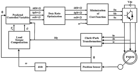
Figure 1.
Overall configuration of DR-MPDSC strategy.
3.1. Estimated Controlled Variables
Based on the matrices defined in Equation (6), the estimated control variables can be expressed in terms of the measured quantities using the following set of equations:
3.2. Predicted Controlled Variables
For enhanced accuracy, the predicted control variables are adjusted using both the measured and estimated values and are represented by the following expressions:
3.3. Optimized Duty Ratio
To enhance torque smoothness and reduce ripple, this method leverages an optimized duty ratio to refine the selection of voltage vectors. This optimization leads to more stable and energy-efficient motor performance by aligning the applied voltage vector more closely with the ideal reference. By accurately regulating the voltage vectors, the duty ratio minimizes the discrepancy between the reference and actual motor speed, particularly under dynamic conditions. This results in improved transient response and overall system dynamics. Additionally, minimizing switching and conduction losses in both the inverter and motor contributes to enhanced efficiency, especially during partial-load operation. The proposed strategy applies a single active voltage vector for a duration defined by the optimized duty ratio, while the remaining portion of the sampling period is allocated to a zero voltage vector. Initially, three candidate voltage vectors are chosen by minimizing the following cost function:
Among these, the vector that further minimizes the secondary cost function in Equation (28) is selected to reduce speed tracking error. The resulting inverter voltage components in the d–q reference frame are computed as follows:
These voltages are then used to predict the next-step stator currents, modified as
The cost function can be rewritten to express the influence of the duty ratio:
where
Minimizing this cost function with respect to the duty ratio yields
Solving this gives the optimal duty ratio as
This approach ensures efficient and accurate voltage application, enhancing control precision while reducing energy losses across varying load conditions.
3.4. Load Torque Compensation
Load torque compensation plays a critical role in enhancing the dynamic performance and robustness of Model Predictive Direct Speed Control (MPDSC) for Permanent Magnet Synchronous Motors (PMSMs) [37,38,39]. Sudden variations in load torque can lead to significant speed fluctuations and control instability, especially in high-performance applications. By incorporating a load torque observer or estimation mechanism within the MPDSC framework, the control algorithm can accurately predict and counteract external torque disturbances. This proactive compensation improves the predictive model’s accuracy, allowing for more precise voltage vector selection and faster convergence to the reference speed. Consequently, the overall system exhibits improved torque response, reduced speed offset, and better resilience against load perturbations. The predicted rotor speed at the next sampling instant, K + 1, as given in Equation (15), is influenced by the load torque—typically an unknown external disturbance. Additionally, variations in PMSM parameters such as the moment of inertia J and viscous friction coefficient B under different operating conditions can introduce prediction errors. To address this issue, a compensation term is proposed to enhance the accuracy of the prediction model, as formulated below:
Here, represents the actual speed measured at time k, while denotes the predicted speed obtained from the previous sampling instant, k − 1; the terms and correspond to the integral components of the speed offset at times k and k − 1, respectively. The equation used to predict the speed can therefore be expressed as
The parameter serves as a tuning coefficient that influences the compensation rate within the prediction equation. When the actual speed exceeds the predicted value, becomes positive, thereby increasing the predicted speed. This adjustment helps to reduce the discrepancy between the actual and predicted speeds, driving the prediction error closer to zero.
The tuning coefficient was selected empirically to balance convergence speed and noise sensitivity of the torque observer. A value of = 0.8 provided fast compensation without inducing oscillations and was consistently applied in both simulation and experimental studies.
3.5. Secondary Cost Function Design
The proposed DR-MPDSC strategy is designed to achieve several critical objectives: accurate tracking of the reference speed, reduction in torque ripples, and enforcement of current constraints. These performance targets are encapsulated by the following cost function:
The cost function components serve the following purposes: The first term minimizes the deviation between the predicted angular velocity and the desired reference speed , with the influence of this term governed by the weight . In this work, the cost function constants are selected as fixed values: = 1 for speed tracking. Owing to the dual-stage cost function design, manual weight tuning is avoided, which simplifies real-time implementation.
The second term, , introduces strict limitations on the stator current magnitudes by applying hard thresholds:
This cost function is evaluated for a set of three voltage vector candidates, which are initially shortlisted based on a primary cost function, . The voltage vector that minimizes is ultimately selected. The evaluation process begins by predicting the voltage components and using the current rotor position. These predicted voltages, along with machine parameters and an estimation of the load torque, are then used to forecast the future speed and current components and . The optimal control action corresponding to the minimum value of the objective function is applied in the subsequent sampling cycle.
The closed-loop stability of the proposed DR-MPDSC is inherently ensured since the control decision at each sampling instant is obtained by minimizing a convex quadratic cost function. The discrete PMSM model is linear and time-invariant within each control interval, which guarantees the boundedness of the predicted states. In addition, the load torque observer introduces an integral compensation term that asymptotically drives the estimation error to zero. Hence, the speed tracking error converges to a small neighborhood of zero, as also verified by the simulation and experimental results presented in Section 4 and Section 5.
4. Simulation Implementation
To rigorously evaluate the performance of the proposed Duty Ratio Model Predictive Direct Speed Control (DR-MPDSC) scheme, comparative simulations were conducted using a MATLAB/Simulink-based platform under identical motor parameters and operating conditions. The testbed modeled a Permanent Magnet Synchronous Motor (PMSM) using the specifications listed in Table 1. Two principal test scenarios were considered: a reference speed step and a sudden application of load torque. To ensure the validity of the assessment, the proposed controller was benchmarked against two widely adopted baseline methods: conventional Field-Oriented Control (FOC) and standard single-vector Model Predictive Direct Speed Control (MPDSC). Both benchmarks were implemented using the same discrete-time PMSM model, a fixed control sampling time of 100 µs, and identical current and voltage constraints. This unified benchmarking setup enabled a direct, unbiased comparison in terms of speed tracking performance, torque ripple, steady-state precision, and robustness to disturbances.

Table 1.
Parameters of studded PMSM.
The first benchmark, Field-Oriented Control (FOC), is a classical technique commonly employed in industrial PMSM drives. It utilizes decoupled d–q-axis current loops regulated via PI controllers, along with pulse-width modulation for voltage synthesis. Although FOC offers reliable steady-state performance, its cascaded loop structure inherently limits dynamic response, and its performance degrades significantly under abrupt load changes [40,41,42].
The second benchmark, the conventional MPDSC, applies a single voltage vector in each control step based on minimizing a weight-tuned cost function incorporating speed error. While this method offers improved transient performance over FOC, it suffers from elevated torque and speed ripples in steady-state conditionsnd exhibits sensitivity to manual weight tuning and parameter mismatches [43].
In contrast, the proposed DR-MPDSC applies optimized combinations of active and zero vectors within each sampling period, eliminating the need for manual weighting. Its dual-stage cost function architecture independently addresses transient response and steady-state ripple, while the integration of load torque disturbance compensation enhances robustness under dynamic conditions. The simulation results clearly demonstrate that DR-MPDSC achieves faster settling time, lower ripple, and superior disturbance rejection, affirming its practical advantages over both conventional benchmarks.
For completeness, it is worth comparing the proposed DR-MPDSC with other advanced control strategies recently reported in the literature. Direct Torque Control (DTC) is known for its fast dynamics but suffers from high steady-state torque ripple. Sliding-mode control (SMC) provides robustness but is highly sensitive to parameter uncertainties and often produces chattering. Backstepping, while effective, typically requires complex modeling and results in higher computational demand. In contrast, the proposed DR-MPDSC achieves low torque ripple and reduced current THD with moderate complexity, which is further supported by the simulation and experimental results presented in this work.
4.1. Step Change in Reference Speed
To analyze the dynamic tracking performance of the proposed (DR-MPDSC) scheme, a sudden step change in reference speed was introduced in the simulation environment. The simulation results, illustrated in Figure 2 and summarized in Table 2, indicate that the DR-MPDSC controller effectively handled the abrupt speed variation with fast dynamic response and high tracking accuracy. The motor speed closely followed the new reference with no overshoot and a steady-state speed offset of just 0.004%. During the acceleration phase, the torque ripple remained as low as 0.0124 Nm, and the current response was stable, with no signs of instability with THD at 5.5%. In contrast, the traditional (FOC) method (Figure 3) exhibited an overshoot of 1.25%, steady-state speed offset of 1.45%, and torque ripple of 0.0845 Nm, while the MPDSC approach (Figure 4) showed 0.55% overshoot, 0.07% steady-state speed offset, and a substantially higher torque ripple of 0.03 Nm.
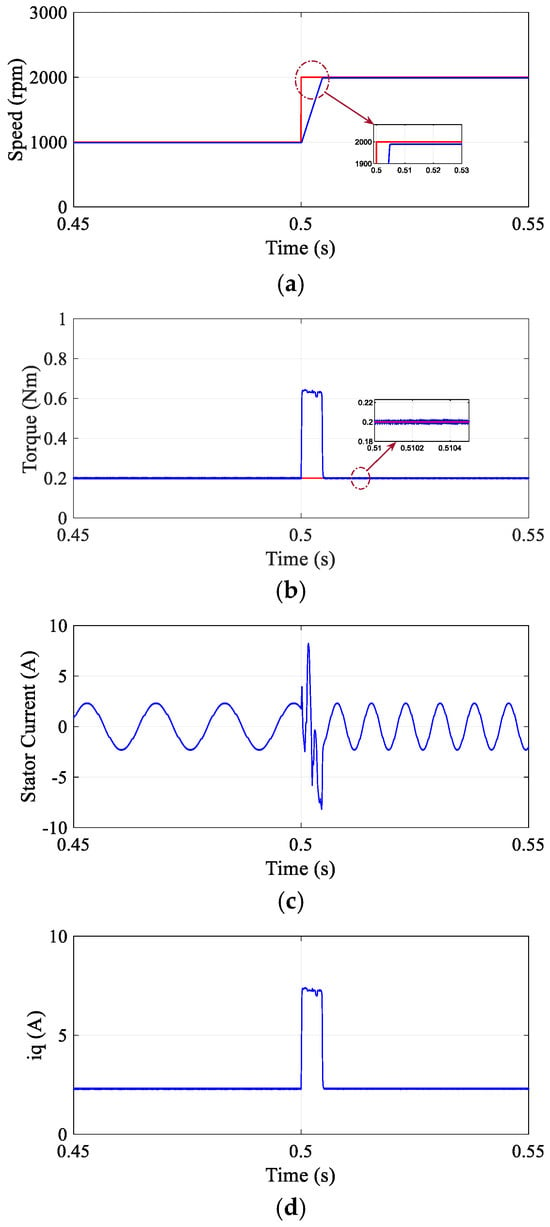
Figure 2.
Transient response of proposed DR-MPDSC during speed step change from 1000 rpm to 2000 rpm. (a) Speed. (b) Torque. (c) Stator current. (d) Quadrature-axis current.
Table 2.
Comparative performance during speed reference step change.
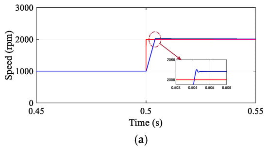
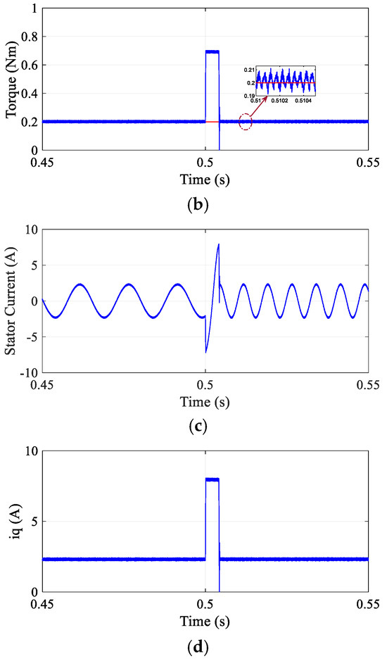
Figure 3.
Transient response of conventional Field-Oriented Control (FOC) during speed step change from 1000 rpm to 2000 rpm. (a) Speed. (b) Torque. (c) Stator current. (d) Quadrature-axis current.
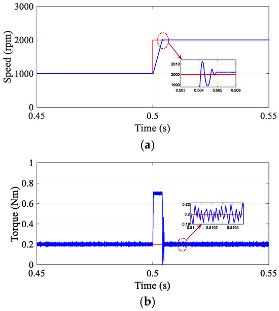
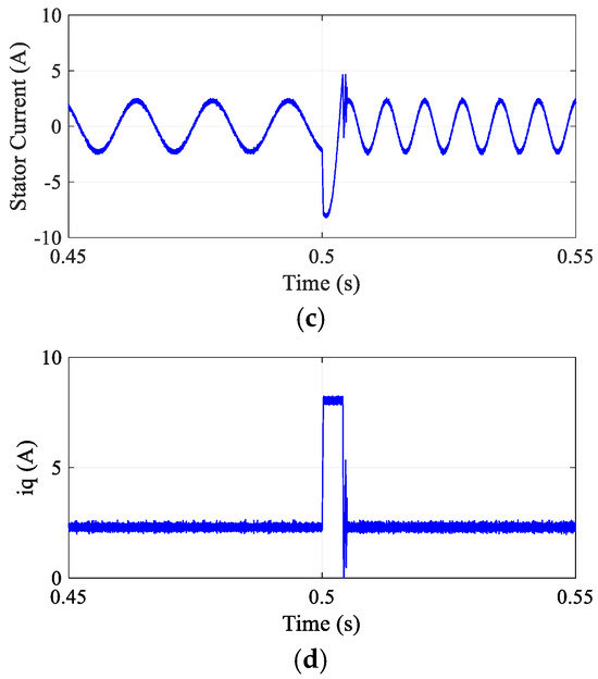
Figure 4.
Transient response of conventional Model Predictive Direct Speed Control (MPDSC) during speed step change from 1000 rpm to 2000 rpm. (a) Speed. (b) Torque. (c) Stator current. (d) Quadrature-axis current.
The predictive nature of the DR-MPDSC algorithm enables timely voltage vector selection, ensuring smooth and efficient speed transitions. These simulation outcomes validate the DR-MPDSC controller’s capability to maintain precise and robust speed control under dynamic operating conditions, highlighting its superior performance and suitability for high-performance applications.
For completeness, it is worth noting that other advanced control methods such as DTC, SMC, and Backstepping have also been reported in the recent literature. However, DTC typically suffers from higher steady-state torque ripples, SMC is highly sensitive to parameter uncertainties, and Backstepping involves greater implementation complexity. In contrast, the proposed DR-MPDSC achieves low ripple, reduced THD, and fast dynamic response with moderate computational effort, as confirmed by the presented results.
4.2. Step Variation in Load Torque
Simulation experiments were carried out to assess the effectiveness of the proposed DR-MPDSC strategy when subjected to sudden variations in load torque on a Permanent Magnet Synchronous Motor (PMSM). To evaluate the controller’s disturbance rejection capabilities, a step load torque disturbance was introduced during steady-state conditions. The results, illustrated in Figure 5, indicate that the DR-MPDSC method successfully sustains precise and stable speed regulation in the presence of abrupt external disturbances. Specifically, the DR-MPDSC achieved a steady-state speed offset of just 0.005% and maintained torque ripples at just 0.0165 Nm, demonstrating excellent dynamic performance. In comparison, the conventional FOC method (Figure 6) exhibited a steady-state speed offset of 1.45% and torque ripples of 0.0855 Nm, while the MPDSC approach (Figure 7) yielded a steady-state speed offset of 0.06% but suffered from substantially higher torque ripples of 0.032 Nm. The system’s speed response with DR-MPDSC displayed only minor deviations and achieved rapid recovery, underscoring the predictive controller’s robustness and responsiveness.
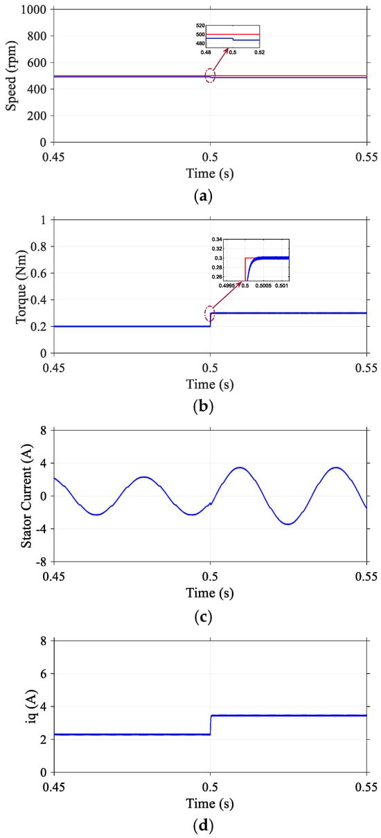
Figure 5.
Transient response of proposed DR-MPDSC under a step change in load torque at a constant speed of 500 rpm. (a) Speed. (b) Torque. (c) Stator current. (d) Quadrature-axis current.
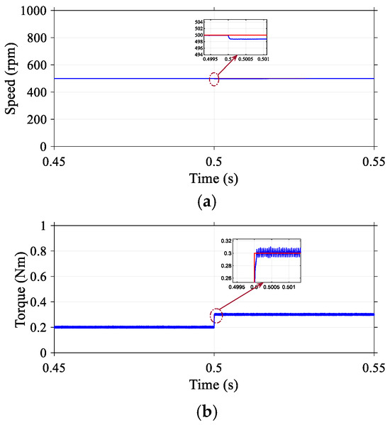
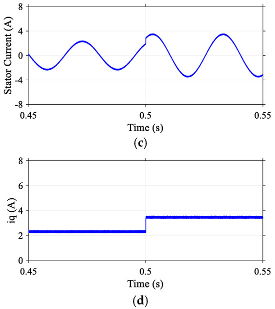
Figure 6.
Transient performance of conventional Field-Oriented Control (FOC) under a step change in load torque at a constant speed of 500 rpm. (a) Speed. (b) Torque. (c) Stator current. (d) Quadrature-axis current.
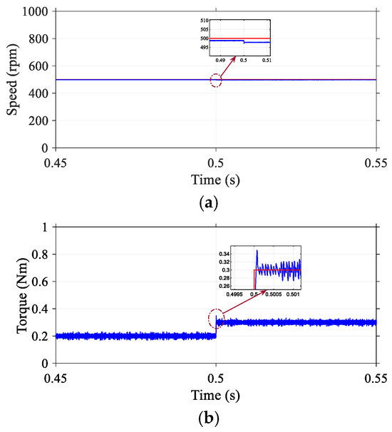
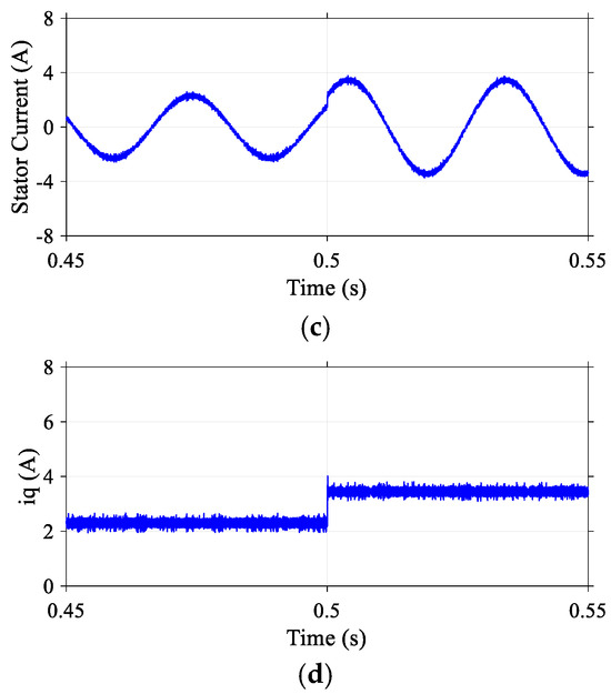
Figure 7.
Transient response of the conventional Model Predictive Direct Speed Control (MPDSC) under a step change in load torque at a constant speed of 500 rpm. (a) Speed. (b) Torque. (c) Stator current. (d) Quadrature-axis current.
The small torque overshoot observed during sudden load disturbances was mainly due to the interaction between the predictive model and the integral torque observer. Nevertheless, its magnitude remained significantly lower than that of conventional FOC and MPDSC, demonstrating improved damping performance.
The waveforms of the stator current were adapted instantaneously to the new torque demand without excessive ripples or transient oscillations. These results confirm that the DR-MPDSC method ensures robust dynamic performance and enhances system stability under varying load conditions.
5. Experimental Implementation
The experimental setup for implementing the proposed Duty Ratio Model Predictive Direct Speed Control (DR-MPDSC) scheme with integrated electromagnetic load torque compensation is illustrated in Figure 8. The test system was built around the dSPACE DS1202 real-time control platform, which was tightly integrated with MATLAB/Simulink for controller design and deployment. The DR-MPDSC algorithm was implemented in Simulink and executed at a fixed 10 kHz sampling frequency via the DS1202 processor, which handled real-time control computation, PWM signal generation, and data acquisition. The PMSM under testing was mechanically coupled to a programmable DC machine functioning as an electromagnetic load emulator, allowing precise emulation of dynamic load torque scenarios. High-resolution optical encoders were used to provide accurate rotor position and speed feedback to the control system, while current and voltage signals were sampled through high-speed ADC channels on the dSPACE board [44,45].
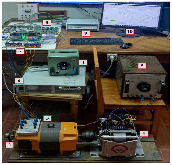
Figure 8.
Hardware components of the experimental setup. (1) PMSM, the primary motor under testing whose parameters are listed in Table 3. (2) Encoder. (3) DC generator. (4) Generator excitation. (5) Loading variable resistance. (6) Programmable DC supply. (7) IGBT-based inverter. (8) Interface board. (9) dSPACE 1202 MicroLabBox. (10) Host PC.
The entire system configuration enabled the reliable testing and validation of advanced predictive control strategies under a range of speed and load conditions, ensuring both robustness and high-performance operation. Real-time current, voltage, rotor position, and other system variables were acquired through the DS1202 platform and monitored via dSPACE ControlDesk. Key signals were logged in using ControlDesk’s Data Acquisition module and exported as (Data.mat) files for post-processing.
The speed, torque, and current waveforms were then reconstructed and analyzed in MATLAB. Since a physical torque sensor was not employed, electromagnetic torque was estimated from the measured stator currents and known motor parameters using the standard PMSM torque equation. This indirect method is well-established in PMSM research and was validated through comparison with the load profiles generated by the DC load emulator. The motor specifications used during the experimental tests are provided in Table 3, and the combined hardware–software setup ensured reliable real-time implementation and accurate performance evaluation of the proposed DR-MPDSC controller.
Table 3.
Parameters of tested experimental PMSM.
It should be clarified that the PMSM used in simulations was not identical to the experimental motor. A smaller-rated motor was adopted for simulations to accelerate numerical evaluation and controller prototyping, while a higher-power laboratory machine was employed in experiments to ensure realistic validation under practical conditions. This dual-motor approach is widely used in predictive control research to balance computational efficiency with experimental accuracy.
5.1. Steady-State Response
Experimental validation of the DR-MPDSC scheme for a PMSM operating at 500 rpm with integrated load torque compensation showed enhanced steady-state performance. As shown in Figure 9, the rotor speed closely tracked the reference with a steady-state speed offset of just 0.4%. The electromagnetic torque response was smooth, with torque ripples limited to 3%, and exhibited minimal overshoot and short settling time, indicating effective damping characteristics of the controller. Stator current waveforms remained sinusoidal and balanced, with a noticeable reduction in harmonic distortion compared to conventional PI-based strategies, confirming the improved current quality and reduced thermal stress on the motor. These results substantiate the DR-MPDSC framework’s robustness and accuracy for precise low-speed operation and high-performance motion control. The measured current THD was approximately 5.5%, which was markedly lower than that obtained with conventional PI-based FOC or single-vector MPDSC. This confirms the improved current quality and reduced harmonic stress on the motor windings.
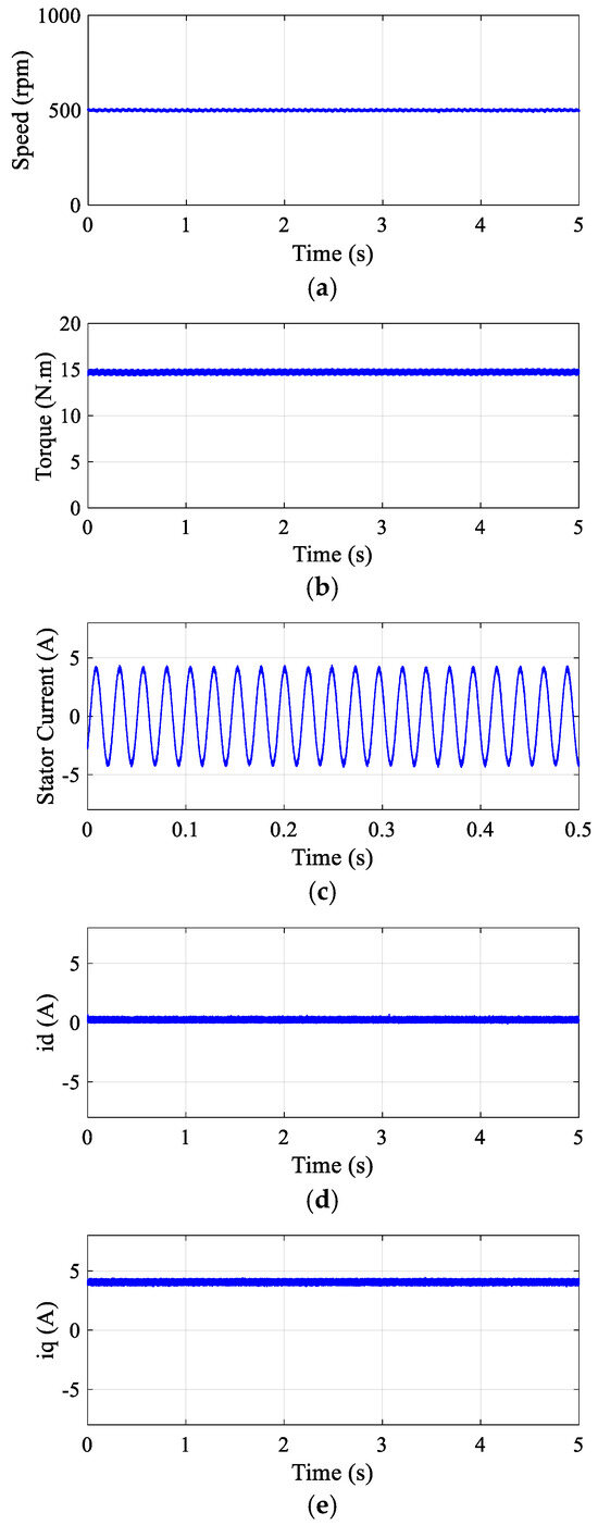
Figure 9.
Steady-state experimental response of the proposed DR-MPDSC method at a constant speed of 500 rpm. (a) Speed. (b) Torque. (c) Stator current. (d) Direct-axis current. (e) Quadrature-axis current.
5.2. Dynamic Response to Load Torque Disturbance
To evaluate the robustness of the proposed (DR-MPDSC) scheme, experiments were conducted under sudden load torque disturbances applied to the Permanent Magnet Synchronous Motor (PMSM). The system was subjected to abrupt increases and decreases in load torque during steady-state operations to observe its dynamic response. The experimental results, illustrated in Figure 10, demonstrate that the DR-MPDSC algorithm effectively compensated for the disturbance, maintaining speed regulation with minimal deviation and fast recovery. Specifically, the speed response exhibited a transient overshoot of just 0.6%, a steady-state speed offset of 0.2%, and torque ripples limited to 2.3%, indicating strong disturbance rejection capability. Additionally, the stator current waveforms adapted smoothly to the load variations without excessive oscillations, confirming the controller’s effective damping and response characteristics. These observations validate the predictive controller’s ability to anticipate and correct the effects of load torque changes in real time, thereby enhancing system stability and performance under dynamic operating conditions.
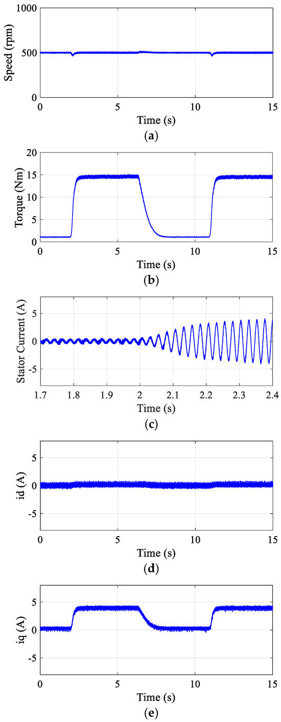
Figure 10.
Experimental transient response of the proposed DR-MPDSC under step load torque variation at a constant speed of 500 rpm. (a) Speed. (b) Torque. (c) Stator current. (d) Direct-axis current. (e) Quadrature-axis current.
During experimental tests, the torque decay was observed to be slower than the torque rise. This asymmetry is mainly attributed to the mechanical inertia of the coupled DC load emulator, which resisted rapid torque reduction. Future work will investigate alternative load emulation setups to further accelerate torque decrease dynamics.
5.3. Dynamic Response to Speed Step
To assess the dynamic response of the proposed DR-MPDSC strategy, a sudden increase in reference speed was applied to the PMSM. The experimental results, illustrated in Figure 11, demonstrate that the controller responded rapidly to the acceleration command, achieving a smooth and swift rise in speed with negligible overshoot and a minimal steady-state error of 0.2%. The DR-MPDSC algorithm effectively predicted the optimal voltage vectors required for fast torque buildup, enabling a quick transition to the new speed setpoint. Throughout the acceleration phase, the stator current remained within acceptable limits, and the motor operated without oscillations or instability. This performance confirms the controller’s ability to handle fast dynamic changes with high accuracy and efficiency, validating its suitability for high-performance motion control applications.
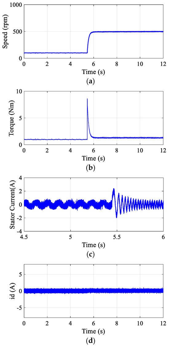
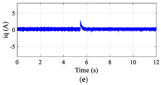
Figure 11.
Experimental transient response of the proposed DR-MPDSC during a speed change from 100 rpm to 500 rpm. (a) Speed. (b) Torque. (c) Stator current. (d) Direct-axis current. (e) Quadrature-axis current.
6. Conclusions
This paper presents an optimized Duty Ratio Model Predictive Direct Speed Control Strategy (DR-MPDSC) for a three-phase Permanent Magnet Synchronous Motor (PMSM), incorporating real-time load torque compensation. By employing a dual cost function framework, the proposed approach effectively minimizes torque and current ripples while achieving fast and accurate tracking of the speed reference. The integration of a load torque observer enhances the system’s ability to compensate for external disturbances, ensuring stable performance under variable operating conditions. Comprehensive validation through both MATLAB/Simulink simulations and experimental implementation confirmed the practical feasibility and robustness of the proposed control scheme. The results demonstrate no speed overshoot, a steady-state speed offset of just 0.05%, and torque ripples limited to 0.0124 Nm, indicating marked improvements in transient response, steady-state accuracy, and disturbance rejection. These results collectively underscore the effectiveness of the DR-MPDSC approach for real-time high-performance PMSM drive systems, particularly in industrial and vehicular applications where dynamic response, precision, and reliability are of paramount importance.
It should also be acknowledged that PMSM drives are affected by a variety of disturbances beyond load torque variation, including current measurement errors, inverter dead-time, unmodeled d–q axis dynamics, cogging torque, flux harmonics, and nonlinear friction in the mechanical subsystem. While the present study has focused primarily on real-time load torque estimation and compensation, extending the proposed DR-MPDSC framework to explicitly address these multi-source disturbances represents a promising direction for future research and industrial application.
From a computational perspective, the proposed DR-MPDSC requires evaluation of only three candidate vectors followed by a closed-form duty ratio calculation, which significantly reduces the number of operations compared with conventional multi-weight MPC. This makes the method suitable for real-time implementation on embedded platforms such as dSPACE DS1202.
Future research directions include extending the proposed DR-MPDSC framework to multi-motor coordinated drive systems, where inter-motor coupling and synchronization pose new challenges. Additionally, adaptive Model Predictive Control formulations may be explored to enhance robustness under parameter uncertainties, sensor noise, and thermal drift in PMSM parameters. Hardware implementation on FPGA or real-time embedded processors will also be considered to further improve computation latency and scalability in industrial applications. Integration with fault diagnosis modules and real-time torque sensor feedback could further elevate system reliability for safety-critical environments such as aerospace and autonomous mobility.
Despite its demonstrated effectiveness, the proposed DR-MPDSC method has certain limitations. First, torque estimation relies on the accuracy of the PMSM parameter set and assumes a linear motor model, which may degrade performance under extreme saturation or temperature variation. The absence of a physical torque sensor limits real-time validation of the torque observer beyond the programmable load emulator. Additionally, the control performance was evaluated under limited load conditions and known motor parameters; broader testing across variable-speed field conditions, mechanical tolerances, and grid disturbances is necessary to fully generalize the controller’s robustness. Future work should address these constraints to ensure broader applicability and industrial readiness.
Author Contributions
All authors contributed to the study conception, methodology design, and implementation. T.Y. developed and implemented the DR-MPDSC algorithm, performed the simulations and experimental validation, and drafted the manuscript. A.A.A., Z.M.S.E. and M.S.A. contributed to the control architecture and critically revised the technical content. M.M.A. (M. M. Ahmed), A.E.Z., and M.M.A. (Mosaad M. Ali) provided guidance on the experimental setup and reviewed the manuscript’s intellectual content. All authors have read and agreed to the published version of the manuscript.
Funding
The authors extend their appreciation to the Deanship of Research and Graduate Studies at King Khalid University for funding this work through the Small Research Project under the grant number RGP2/225/45.
Data Availability Statement
All required data are included in the text and are available upon request from the corresponding author.
Conflicts of Interest
The authors declare no conflicts of interest.
References
- Tian, Y.; Zhang, Y.; Xiao, X.; Yildirim, T. Weighting factors design in model predictive direct torque control based on cascaded neural network. Asian J. Control 2024, 26, 1323–1338. [Google Scholar] [CrossRef]
- Hou, L.; Guo, Y.; Ba, X.; Lei, G.; Zhu, J. Efficiency Improvement of Permanent Magnet Synchronous Motors Using Model Predictive Control Considering Core Loss. Energies 2024, 17, 773. [Google Scholar] [CrossRef]
- He, H.; Gui, H.; Shao, H.; Gao, J. Model Predictive Direct Torque Control Based on Active Disturbance Rejection Controller for PMSM. In Proceedings of the 2022 International Conference on Mechanical and Electronics Engineering, ICMEE, Xi’an, China, 21–23 November 2022. [Google Scholar] [CrossRef]
- Pancurak, L.; Jure, T.; Kyslan, K. Finite Control Set Model Predictive Direct Speed Control of PMSM. In Proceedings of the 2023 International Conference on Electrical Drives and Power Electronics, EDPE, Poprad, Slovakia, 25–27 September 2023. [Google Scholar] [CrossRef]
- Yahia, T.; Ahmed, A.A.; Elzawawi, A.; Ahmed, M.M. Model Predictive Direct Speed Control of PMSM with Load Torque Compensation. In Proceedings of the 2021 24th International Conference on Electrical Machines and Systems (ICEMS), Gyeongju, Republic of Korea, 31 October–3 November 2021; IEEE: Piscataway, NJ, USA, 2021; pp. 1335–1341. [Google Scholar]
- Chi, X.; Wang, C.; Wu, Q.; Yang, J.; Lin, W.; Zeng, P.; Li, H.; Shao, M. A ripple suppression of sensorless FOC of PMSM electrical drive system based on MRAS. Results Eng. 2023, 20, 101427. [Google Scholar] [CrossRef]
- Johny, N.; Paul, M. FOC of PMSM Employed with BDC for EV Application. In Lecture Notes in Electrical Engineering; Springer: Berlin/Heidelberg, Germany, 2023. [Google Scholar] [CrossRef]
- Vidlak, M.; Makys, P.; Gorel, L. A Novel Constant Power Factor Loop for Stable V/f Control of PMSM in Comparison against Sensorless FOC with Luenberger-Type Back-EMF Observer Verified by Experiments. Appl. Sci. 2022, 12, 9179. [Google Scholar] [CrossRef]
- Tejavathu, R.; Bukkana, T.; Tangirala, I.; Poondla, D.K. DTC-SPWM based Realization of SVM with Reduced carrier for Three-level NPC fed Five Phase Permanent Magnet Synchronous Motor Drive. In Proceedings of the 2023 IEEE IAS Global Conference on Emerging Technologies, GlobConET, London, UK, 19–21 May 2023. [Google Scholar] [CrossRef]
- Zhang, W.; Liu, C.; Lian, C.; Liu, J.; Mai, Z. Optimization of SVPWM Algorithm used in PMSM DTC. In Proceedings of the 2023 3rd International Conference on Electrical Engineering and Mechatronics Technology, ICEEMT, Nanjing, China, 21 July 2023. [Google Scholar] [CrossRef]
- Sribumrung, P.; Nungam, S. Direct Torque Control of Permanent Magnet Synchronous Motors using Feedback Passivation. Prz. Elektrotechniczny 2023, 2023, 28–36. [Google Scholar] [CrossRef]
- Gao, S.; Wei, Y.; Qi, H.; Zhang, D.; Wei, Y. Model Prediction Hybrid Parallel Direct Speed Control of Permanent Magnet Synchronous Machines for Electric Vehicles. Control Eng. Appl. Inform. 2022, 24, 31–39. [Google Scholar]
- Wang, H.; Zhang, S.; Liu, W.; Geng, Q.; Zhou, Z. Finite control-set model predictive direct speed control of a PMSM drive based on the Taylor series model. IET Electr. Power Appl. 2021, 15, 1452–1465. [Google Scholar] [CrossRef]
- Wen, B.; Liu, K.; Zhou, J.; Zhou, S.; Hu, W.; Chen, Y.; Huang, C.; Huang, Q. Real-Time Estimation of PMSM Rotor Flux Linkage for EV Application under Steady State and Free-Running Conditions. World Electr. Veh. J. 2022, 13, 83. [Google Scholar] [CrossRef]
- Omar, A.; Wood, A.; Laird, H.; Gaynor, P. Real-Time Emulation of a PMSM-Loaded MMC With BESS. IEEE Access 2023, 11, 55035–55045. [Google Scholar] [CrossRef]
- Wang, M.; Liu, Y.; Wang, Q.; Wheeler, P. Current-constraint speed regulation for PMSM based on port-controlled Hamiltonian realization and deep deterministic policy gradient. IEICE Electron. Express 2024, 21, 20230516. [Google Scholar] [CrossRef]
- Zhang, J.; Ren, W.; Sun, X.M. Current-Constrained Adaptive Robust Control for Uncertain PMSM Drive Systems: Theory and Experimentation. IEEE Trans. Transp. Electrif. 2023, 9, 4158–4169. [Google Scholar] [CrossRef]
- Wang, Y.; Yu, H.T.; Niu, S.X.; Gu, J.P.; Liu, Y.L.; Cheng, F.; Xia, T.; Zhang, W. Adaptive observer-based current constraint control for electric vehicle used PMSM. Appl. Energy 2024, 360, 122802. [Google Scholar] [CrossRef]
- Khanh, P.Q.; Anh, H.P.H. Novel Sensorless PMSM Speed Control Using Advanced Fuzzy MRAS Algorithm. Arab. J. Sci. Eng. 2022, 47, 14531–14542. [Google Scholar] [CrossRef]
- Xu, S.; Chen, X.; Liu, F.; Wang, H.; Chai, Y.; Zheng, W.X.; Chen, H. A Novel Adaptive SMO-Based Simultaneous Diagnosis Method for IGBT Open-Circuit Faults and Current Sensor Incipient Faults of Inverters in PMSM Drives for Electric Vehicles. IEEE Trans. Instrum. Meas. 2023, 72, 3526915. [Google Scholar] [CrossRef]
- Zhang, J.; Ren, W.; Li, J.; Sun, X.M. Adaptive Neural Asymptotic Tracking Control for PMSM Systems under Current Constraints and Unknown Dynamics. IEEE Trans. Circuits Syst. II Express Briefs 2024, 71, 777–781. [Google Scholar] [CrossRef]
- Parvathy, M.S.; Thampi, G.; Raghavendra, N. An efficient Feed-forward compensation mechanism for NFC-based PMSM system using different observers for Load-torque estimation. Int. J. Electr. Electron. Res. 2023, 11, 1–9. [Google Scholar] [CrossRef]
- Shan, D.; Wang, D.; He, D.; Zhang, P. Position Sensorless Vector Control System for Lawnmower Permanent Magnet Synchronous Motor Based on Extended Kalman Filter. Energies 2024, 17, 1230. [Google Scholar] [CrossRef]
- Chen, Z.; Liu, Y. Sensorless control of marine permanent magnet synchronous propulsion motor based on adaptive extended Kalman filter. Front. Energy Res. 2022, 10, 1037595. [Google Scholar] [CrossRef]
- Fan, Y.; Chen, J.; Zhang, Q.; Cheng, M. An Improved Inertia Disturbance Suppression Method for PMSM Based on Disturbance Observer and Two-Degree-of-Freedom PI Controller. IEEE Trans. Power Electron. 2022, 38, 3590–3599. [Google Scholar] [CrossRef]
- Sandre-Hernandez, O.; De Jesus Rangel-Magdaleno, J.; Morales-Caporal, R. Modified model predictive torque control for a PMSM-drive with torque ripple minimisation. IET Power Electron. 2019, 12, 1033–1042. [Google Scholar] [CrossRef]
- Zhao, J.; Fu, Z.; Huo, J.; Zhang, G.; Yang, H.; Wang, S.; Wang, G.; Xu, D. Direct Torque Control Speed Ripple Suppression Method for Permanent Magnet Synchronous Motor Based on Load Torque Observation. In Proceedings of the IECON Proceedings (Industrial Electronics Conference), Penang, Malaysia, 6–7 November 2023. [Google Scholar] [CrossRef]
- Shao, B.; Zhu, Z.Q.; Yan, L.; Feng, J.; Guo, S.; Li, Y.; Feng, L. Torque Ripple Reduction for Direct Torque Control of Dual Three-Phase PMSM Based on Multiple Virtual Voltage Vectors. IEEE Trans. Energy Convers. 2023, 38, 296–309. [Google Scholar] [CrossRef]
- Sadhukhan, T.; Roy, P.; Ray, S. Direct Torque Control of PMSM following Advanced Duty Ratio Modulation with MTPA Scheme. In Proceedings of the 2023 IEEE 3rd Applied Signal Processing Conference, ASPCON, Haldia, India, 24–25 November 2023. [Google Scholar] [CrossRef]
- Du, N.; Ge, L. A Novel Duty Ratio Interval Subdivision Based MPTC Method for PMSM. In Proceedings of the 2023 26th International Conference on Electrical Machines and Systems, ICEMS, Zhuhai, China, 5 November 2023. [Google Scholar] [CrossRef]
- Li, X.; Zhang, S.; Zhang, C.; Zhou, Y.; Yuan, X.; Dong, Y. Model Predictive Control With Duty Ratio Modulation for Open-Winding PMSM Drives With Common DC Bus. IEEE Trans. Power Electron. 2023, 38, 15287–15299. [Google Scholar] [CrossRef]
- Zhang, X.; Zhang, C. A Simple Model Predictive Control for Open Winding PMSM Based on Duty Ratio Control. In Proceedings of the 2023 IEEE 6th International Electrical and Energy Conference, CIEEC, Hefei, China, 12–14 May 2023. [Google Scholar] [CrossRef]
- Sun, J.; Cui, J.; Ma, S. Robustness Enhanced Predictive Control for Dual Three Phase PMSM with Duty Ratio Modulation and Parameter-Free Solution. J. Phys. Conf. Ser. 2023, 2530, 012030. [Google Scholar] [CrossRef]
- Lemma, B.D.; Pradabane, S. Control of PMSM Drive Using Lookup Table Based Compensated Duty Ratio Optimized Direct Torque Control (DTC). IEEE Access 2023, 11, 19863–19875. [Google Scholar] [CrossRef]
- Belkhadir, A.; Pusca, R.; Belkhayat, D.; Romary, R.; Zidani, Y. Analytical Modeling, Analysis and Diagnosis of External Rotor PMSM with Stator Winding Unbalance Fault. Energies 2023, 16, 3198. [Google Scholar] [CrossRef]
- Kulkarni, S.; Thosar, A. Performance Analysis of Permanent Magnet Synchronous Machine due to Winding Failures. Int. J. Electr. Electron. Res. 2021, 9, 76–83. [Google Scholar] [CrossRef]
- Li, H.; Li, S.; Yan, Y. Disturbance observer based MPC for PMSM with multiple disturbances. In Proceedings of the 2023 IEEE International Conference on Predictive Control of Electrical Drives and Power Electronics, PRECEDE, Wuhan, China, 16–19 June 2023. [Google Scholar] [CrossRef]
- Ding, S.; Hou, Q.; Wang, H. Disturbance-Observer-Based Second-Order Sliding Mode Controller for Speed Control of PMSM Drives. IEEE Trans. Energy Convers. 2022, 38, 100–110. [Google Scholar] [CrossRef]
- Yim, J.; You, S.; Lee, Y.; Kim, W. Chattering Attenuation Disturbance Observer for Sliding Mode Control: Application to Permanent Magnet Synchronous Motors. IEEE Trans. Ind. Electron. 2022, 70, 5161–5170. [Google Scholar] [CrossRef]
- Luo, Y.C.; Zheng, H.H.; Lin, C.H.; Kuo, Y.P. Field-oriented Controlled Permanent Magnet Synchronous Motor Drive with Dynamic-parameter Speed Controller Based on Generalized Regression Neural Network. Sens. Mater. 2021, 33, 1945–1955. [Google Scholar] [CrossRef]
- Shriwastava, R.; Thakre, M.P.; Choudhari, J.; Kadlag, S.S.; Mapari, R.; Kadam, D.P.; Khule, S. Performance analysis of FOC space vector modulation DCMLI driven PMSM drive. Bull. Electr. Eng. Inform. 2023, 12, 2682–2692. [Google Scholar] [CrossRef]
- Djelamda, I.; Bochareb, I. Field-oriented control based on adaptive neuro-fuzzy inference system for PMSM dedicated to electric vehicle. Bull. Electr. Eng. Inform. 2022, 11, 1892–1901. [Google Scholar] [CrossRef]
- Gao, M.; Liu, H. Direct speed predictive control of permanent magnet synchronous motor. In Proceedings of the 2023 3rd International Conference on Intelligent Power and Systems, ICIPS, Shenzhen, China, 20–22 October 2023. [Google Scholar] [CrossRef]
- Ahmed, A.A. Experimental implementation of model predictive control for permanent magnet synchronous motor. Int. J. Electr. Comput. Energetic Electron. Commun. Eng. 2015, 9, 644–647. [Google Scholar]
- Wang, N.; Bai, H.; Ma, R.; Huang, G. FPGA-based Real-Time Simulation of Five-Phase PMSM for the HIL Applications. In Proceedings of the 2022 4th International Conference on Smart Power and Internet Energy Systems, SPIES, Beijing, China, 27–30 October 2022. [Google Scholar] [CrossRef]


Disclaimer/Publisher’s Note: The statements, opinions and data contained in all publications are solely those of the individual author(s) and contributor(s) and not of MDPI and/or the editor(s). MDPI and/or the editor(s) disclaim responsibility for any injury to people or property resulting from any ideas, methods, instructions or products referred to in the content. |
© 2025 by the authors. Licensee MDPI, Basel, Switzerland. This article is an open access article distributed under the terms and conditions of the Creative Commons Attribution (CC BY) license (https://creativecommons.org/licenses/by/4.0/).