1. Introduction
The trend towards individuality and shorter product life cycles demands that modern production systems swiftly adapt to product changes [
1] while maintaining a high degree of automation. To satisfy these demands, we propose the concept of software-defined value stream process systems (SVPSs) that enable automatic reconfiguration of machine tools based on product requirements and machine capabilities. These systems represent a significant advancement in manufacturing by leveraging Digital Twins and software-driven tools to dynamically adjust processes, machines, and tools. Through this integration, SVPSs ensure efficient planning, simulation, and adaptation to diverse production needs, combining machine, tool, and product models with configurable processes and a versatile physical machine kit into a single pipeline.
Product changes, such as the need to change between process types in the value stream of a product or to change tolerance specifications for processes in a product, are the trigger for such reconfiguration. To optimize efficiency in production, the product features and the machine capabilities have to be considered equally. The task is to find a product that satisfies the customer’s requirements and to find a machine configuration that is optimal for manufacturing this product.
Among the current production systems, reconfigurable manufacturing systems (RMSs) offer the best potential for rapid, cost-effective adaptation while maintaining high productivity [
2]. RMSs utilize modular, reconfigurable machine tools (MRMTs), which can be reconfigured quickly to meet customer demands, as supported by Mehrabi et al. [
3] and Padayachee and Bright [
4]. These tools, designed for specific machining features, consist of basic and add-on modules that can be assembled or disassembled as needed. Extensive research has aimed at enhancing MRMTs through open standards, control architecture, algorithms, and optimization metrics [
5].
In Software-Defined Manufacturing (SDM) [
6,
7], integrating machines’ physical behavior with digital machine images allows for complete digital planning and control, where physical processes follow digital specifications and machines can make automated decisions. However, manual intervention remains necessary, and production machines are often rigid and specialized. Agile production systems address heterogeneous product groups with limited usability [
8]. Preliminary work in the Value Stream Kinematics project has explored eliminating the restriction of machine tools to specific processes using standardized kinematics based on six-axis industrial robots [
9,
10,
11]. There remains a need for specialized machine tools with process-specific dynamic properties, especially for high-quality demand processes. Research has investigated adjustable damping systems to adapt machining stability [
12,
13,
14].
In soft robotics, new concepts for continuously growing links (robot axes) are being studied, but these approaches primarily manipulate geometric dimensions and are mostly irreversible [
15,
16]. Other relevant technical properties for production machines remain unadaptable, and using polymer materials results in insufficient basic technical properties. Studies have only examined individual property adaptations, like stiffness or resonance behavior [
17,
18,
19].
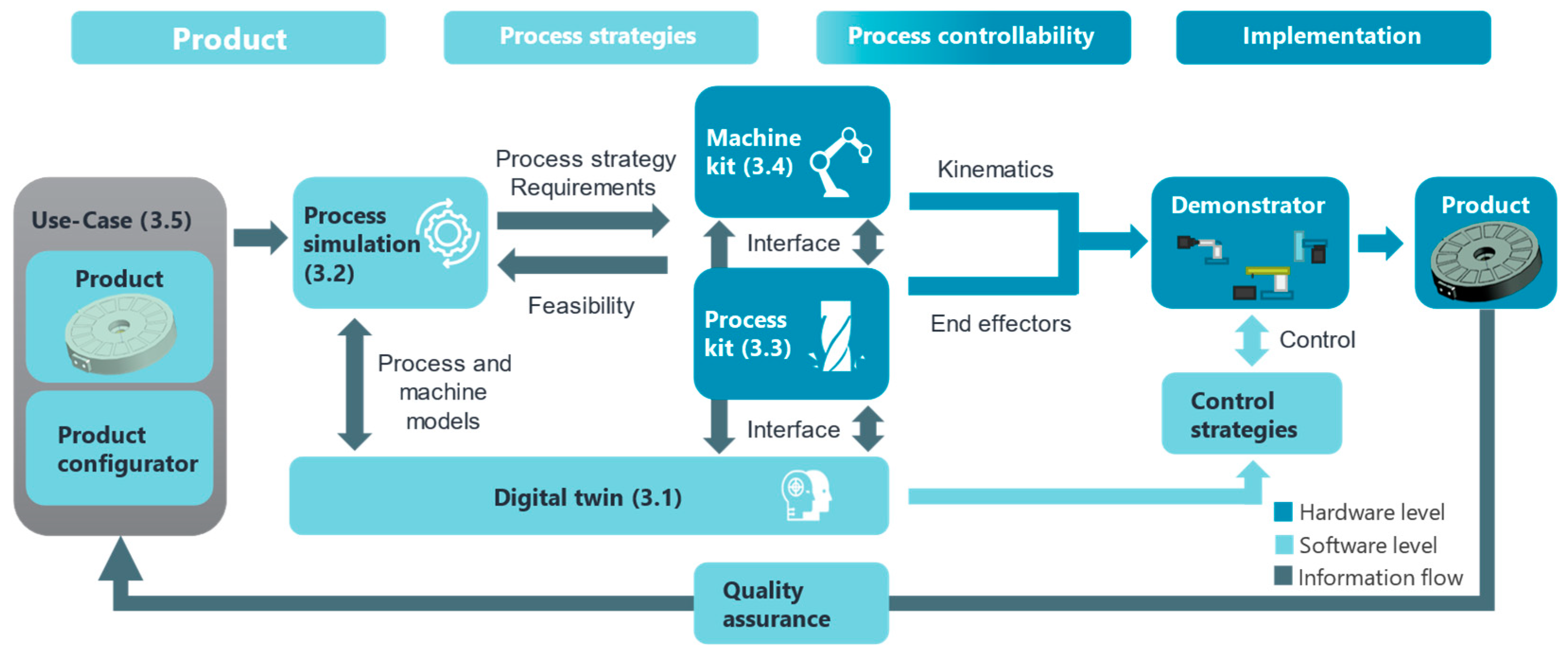
The critical aspect of automating the reconfiguration process is still missing. Addressing this gap is essential for faster changes and overcoming the skilled worker shortage. Our approach aims to bridge this gap by integrating Software-Defined Manufacturing with MRMT into a single workflow concept, the SVPS, shown in
Figure 1. This integration allows automatic reconfiguration based on specific product requirements. Using an electrical machine product as an example, this approach demonstrates autonomous reconfiguration from product design to mapping features to machine tools and kinematics.
2. State of the Art
A suitable software environment is necessary to enable the autonomous reconfiguration of the system and product features. For SVPSs, models for the machine, tools, and product, as well as interfacing models, are required. A Digital Twin, which encompasses all machine and tool models, is required for digital planning and control (
Section 2.1). An exemplary product is used as a demonstrator to validate the novel manufacturing system presented in this article (
Section 2.2). The development of products for SVPS has excellent potential but faces specific challenges, such as aligning functional product requirements with design realization. Therefore, a product configurator is presented (
Section 2.3). SVPS, which dynamically adapts to the specific products and their required quantities, requires a software-based selection of processes addressed by a process kit (
Section 2.4). Furthermore, process simulation is needed (
Section 2.5). A machine kit is used to adapt the characteristics of machine tools to the different requirements of manufacturing a specific product (
Section 2.6).
2.1. Digital Twins
As described above, autonomous planning and execution of manufacturing processes require a digital representation of all components involved in production. This representation is often referred to as a Digital Twin, although there is no generally accepted definition of the term. Generally, a Digital Twin is a virtual representation of a real object, system, or process with which the real counterpart’s properties, states, and behaviors can be calculated, simulated, and controlled [
20]. As such, it is an essential component of digitalization and Industry 4.0. Digital machine images depict the physical behavior of machines and the resulting interactions for product manufacturing [
7]. Their integration in the Software-Defined Manufacturing context enables complete digital planning and control of production [
6]. An essential aspect of the Digital Twin is that it not only imitates real behavior but can also be used to analyze the properties and behavior under different environmental and boundary conditions. The real object can thus be influenced by feeding back suitable signals.
A distinction can also be made when implementing Digital Twins based on the degree of integration. Kritzinger et al. [
21] provide a proposal for the classification into Digital Model, Digital Shadow, and Digital Twin:
Digital Model: a digital representation of an object without automated data exchange between real and digital objects. This can include simulation models that use physical data for the creation of the model but with manual data exchange, so physical and digital models do not affect each other.
Digital Shadow: a digital representation with an automated data flow in one direction from the physical to the digital object. A change of the real object leads to a change of the digital object.
Digital Twin: a digital representation with an automated data exchange in both directions. This means that the Digital Twin not only represents the current state of the physical object but can also be used as a controlling instance for the real object. A visual representation of this is given in
Figure 2 below.
This categorization is used within this paper with the term digital image for general description when an exact classification is not necessary.
In addition to the lack of a standardized definition, there is no standardized format for describing a Digital Twin and its physical properties. Its characteristics are highly dependent on the application [
22]. This also means they are usually created with a specific application in mind and are not very flexible for other applications. There are several approaches to creating a framework for Digital Twins to reduce the effort required to create them [
23,
24].
One aspect of the digital model of machines that is particularly relevant to this work is the description of machine kinematics and dynamics. A common option, which is mainly used in the robotics field, is the Unified Robot Description Format (URDF), which describes the kinematic and dynamic parameters in a standardized Extensible Markup Language file (XML) and can be used by various simulation and visualization environments [
25].
A different approach to the definition is proposed by Worden et al. [
26]. The term “twin” is deliberately avoided, and the term “mirror” is used instead to emphasize the property of replicating the physical system. Definitions of the terms ε-mirror and Turing mirror are also presented to classify the quality of the mirror and to illustrate the achievable accuracy. Since integration into an automated process is the main focus of this paper and the data flow is relevant, the following sections will use the widely accepted definition according to Kritzinger et al. presented above.
For use in industry, an SVPS machine must be suitably validated and certified. For this, the overall requirements of the digital chain must be validated, and methods like the eight-step procedure proposed by Sargent [
27] must be used. In order to validate the overall chain based on the requirements, the individual sub-modules must be verified and qualified. This can be done, for example, with the above-mentioned ε-mirror or with methods from Kleijnen [
28], who focuses on process simulation classification.
2.2. Product: Electrical Machine
The definition and design of a sample product enable extensive testing of the new production system. In this case, an electrical machine (EM) is utilized as a demonstrator product. EMs are electromechanical energy converters using magnetic energy as an intermediate energy form and unintentionally converting fractions of the power flow to heat. Consequently, the four physical domains of mechanics, electronics, magnetics, and thermodynamics influence the resulting and achievable product behavior during operation [
29]. Therefore, an EM consists of subsystems that individually fulfill subfunctions from one or two of the mentioned domains. The latter is the case if the subsystem fulfills an interface role between different domains. The interactions between individual subsystems vary greatly in the number and complexity of their interdependencies and form a highly complicated overall system behavior [
30]. Particularly in the active zone of the EM, there are diverse and highly non-linear interactions between the four domains mentioned and the subsystems involved, such as the coil winding system, the soft magnetic cores, the cooling system, and the structural components that absorb the mechanical loads [
31]. However, for the actual operation of an electrical machine, additional peripheral subsystems not located directly in the active zone of the EM are usually required. Examples of these subsystems are the bearing system, the sealing system, or the bearing shields [
29]. Located outside the active zone, these subsystems are characterized by less interaction with the other domains, so the subsystems mentioned mainly fulfill mechanical functions. Accordingly, the density of functional integration is lower for these peripheral subsystems, which leads to increased manufacturability. Therefore, starting from the peripheral subsystems and moving on to the subsystems belonging to the active zone, EMs offer the possibility of testing and further developing the novel production process at increasing levels of difficulty [
32,
33]. However, a suitable type and design of the electrical machine must be elaborated to fulfill these desired properties.
2.3. Product Configurator
The development and manufacture of products for SVPSs offer significant potential for the future design of production environments. To fully exploit this potential, the specific challenges and requirements that must be considered when designing such products must be identified. One challenge is the type of information in the product models used [
34,
35]. A critical aspect in this context is aligning functional product requirements with their design realization during product development [
36,
37]. To date, there are no methods to ensure the functional quality of the products to be manufactured [
38].
2.4. Process Kit and Process Modules
The current state of research in end effectors for process technologies such as milling or component handling is on permanently installed and non-convertible systems. Verl et al. [
39] gave an overview of current developments in industry and research on industrial robots (IR).
Consequently, current production systems often lack the necessary adaptability and scalability to effectively respond to the rapidly evolving and variable demands of contemporary markets up to now, there have been approaches for an adaptable production system, as demonstrated by Möhring [
40], but other methods have tended to exist as isolated solutions as shown by ElMaraghy et al. [
41]. Therefore, a primary objective should be to advance the development of universal production systems, which serve as cost-efficient and sustainable solutions for achieving adaptability in manufacturing processes. For instance, one approach being pursued involves adapting existing production systems by utilizing and interconnecting sensor and actuator data. This strategy aims to evolve these systems into Self-Optimizing Manufacturing Systems (SOMSs), which can autonomously enhance their performance and efficiency [
42].
To realize a versatile and sustainable production for the future, this approach needs to be expanded beyond its current scope to include broader aspects of software and hardware integration, as Bergs et al. show [
43]. The outcome of this expanded approach is a production system that dynamically adapts to the specific product and its required quantity. This system can be reconfigured or repurposed in a modified form, thereby establishing a modular framework composed of interlinked subsystems, including hardware and software components. Bleicher et al. have summarized approaches for sensors and actuators in production systems through intelligent tools [
44].
The processes must first be characterized to make a software-related selection of processes for certain products. According to DIN [
45], manufacturing processes can be fundamentally categorized into the main groups: “primary forming”, “forming”, “cutting”, “joining”, “coating”, and “changing material properties” (source). Contrary to the “universality” approach, SVPS are targeting reconfigurable, process-specific solutions that, when combined, can implement almost any manufacturing process chain on a diverse range of components to manufacture a wide variety of products in a software-driven, demand-orientated manner. Based on a decomposition of exemplary production parts, a solution space consisting of process modules to be provided ad hoc is initially defined here. Each process module is characterized by its technology (e.g., fused deposition modeling [FDM] 3D printing, milling, joining, gripping), a characteristic parameter field (e.g., performance, speed, gripping range), and capability features (e.g., range of materials, accuracy, rigidity). Finally, the integration of sensor technology is analyzed, providing subsequent information sources for digital images.
2.5. Process-Simulation
Commercially marketed computer-aided design/manufacturing (CAD-CAM) systems make it possible to recognize features on components from the design and to derive manufacturing operations to a limited extent. A focus on artificial intelligence was also used early on to identify different features. In 2001, Öztürk [
46] presented a neural network for recognizing non-standardized complex shape features. Using CAD-CAM systems, these recognized geometric features can be assigned to machining processes. However, machine influences on component quality and tolerances are not considered. For this reason, a conservative process design is used, which does not utilize the existing performance and rigidity of the machine to avoid critical components or machine states. As a result, machines are oversized in rigidity and drive power, resulting in large moving masses and unnecessary energy consumption.
However, if machines are undersized for a process strategy, this can lead to tool failure due to overloading caused by vibrations or excessive deviation of the process variables. In addition to damage to the tool, the required component qualities and tolerances cannot be met [
47].
In addition to pure error prevention, AI can also be used to optimize the program code and tool paths. Hatem et al. [
48] provide a good overview of various applied optimization algorithms, with a focus on minimizing non-productive times and tool paths.
In addition to these points, it is important to take into account the machine’s acceleration. Fok et al. [
49] used an artificial neural network to bypass a computationally intensive path optimization. The proposed solver requires, on average, 33.99% less computing time than the greedy algorithm when optimizing tool paths without resulting in a poorer machining result.
Popular AI methods also enable a wide range of applications. Šket et al. [
50] show the possibilities and limitations of ChatGPT-3.5 and ChatGPT-4o when generating CNC code with ISO G-code. Difficulties arise with complex operations such as milling, while good results are achieved with simpler operations such as drilling. Despite the progress made, ChatGPT-4o cannot yet replace traditional CAM programming, especially for complex operations.
2.6. Machine Kit
Machine tools comprise four main assemblies critical to generating relative motion between the tool and the workpiece: the frame, the guideway, the drive, and the control system. The frame is the machine’s structural foundation, holding components in place and absorbing mechanical and thermal loads. Frames are designed as open or closed structures depending on the machine’s force flow, with open frames offering better accessibility at the expense of potential structural deflection under machining forces. Guides mounted on the frame are integral to the precise guidance of axis movements, facilitating the accurate execution of both rotary (rotary guides) and linear (linear guides) motions. Drives convert electrical, hydraulic, or pneumatic energy into mechanical energy, distinguishing between primary motors for energy conversion and gears for mechanical energy conversion. They include main and auxiliary drives for specific tasks requiring high dynamic and static drive stiffness and high geometric and kinematic accuracy [
51]. Machine tool controls automate operations and guide tools along programmed paths to shape workpieces. Key components include input sensors, processors, and output actuators. To facilitate flexible production, control systems must be adaptable, capable of rapid reprogramming, and equipped with real-time monitoring, simulation, and adjustment capabilities.
The design of these essential machine tool components, particularly the frame and guideways, prioritizes balancing structural integrity with the precision required for effective operations. In contrast, drives necessitate high stiffness and accuracy to function optimally. Modular and reconfigurable machine tools have established themselves as vital solutions to address the need for flexibility and efficiency in production.
These tools facilitate rapid reconfiguration through interchangeable modules, significantly reducing the development and setup time associated with new product cycles. This modular approach was highlighted in research by Heisel and Michaelis in 1998 [
52] and further explored by Abolhassan in 2013 [
53]. These interchangeable modules can be purchased or rented as needed. This is a great advantage over conventional machines because it eliminates the need to invest in additional flexibility when initially purchasing a new machine [
54].
While design tools for creating suitable configurations from functional requirements exist, as developed by Hammadi et al. [
55], they start from the requirements that each module of the MRMT is able to provide. This allows them to verify their configurations using CAD and other tools, e.g., for Deflection analysis. This approach, however, limits the ability to efficiently generate these designs automatically from process simulation data.
2.7. Research Gap
In conclusion, enabling autonomous reconfiguration in production systems requires a robust software environment, with Digital Twin playing a key role in digital planning and control. While this technology shows great potential, challenges such as the lack of a standardized definition and format for Digital Twins limit their flexibility across different applications. The section also highlights the need for a product configurator to address the gap in aligning functional product requirements with design realization. Additionally, while process kits and simulations offer adaptability, there is still a need for more advanced methods to account for machine influences on quality and tolerances in process design. Current solutions for modular and reconfigurable machine tools demonstrate the potential for flexible production. However, further research is required to develop universal systems that can dynamically adapt to varying product demands in real-time.
3. Software-Defined Value Stream Process—Conceptual Process Chain
The advancement of autonomous reconfiguration in production systems depends on a flexible software environment, with Digital Twins central to digital planning, process control, and real-time adaptation. However, challenges remain, including the lack of a standardized Digital Twin definition and limitations in aligning product requirements with design realization.
The Software-Defined Value Stream, as part of SVPSs, is introduced as a solution to address these issues. SVPSs integrate the Digital Twin, modular, reconfigurable machine tools (MRMTs), and process simulations to create an adaptable production environment. It optimizes product design, manufacturing, and quality assurance using a product configurator, CAD/Product Manufacturing Information (PMI) models, and machine kits, offering a dynamic, reconfigurable solution.
This section presents the conceptual process chain for SVPS, detailing the steps from product design to realization on the machine. An overview is shown in
Figure 1. The conceptual SVPS process chain focuses on three major steps:
Process Strategies are defined through Process Simulation (
Section 3.2), optimizing the tool path, manufacturing technology, and system requirements under set constraints.) The Digital Twin (
Section 3.1) maps the requirements of the product and process to the capabilities of the machine;
Process Controllability leverages the Digital Twin, along with the process kit (
Section 3.3) and machine kit (
Section 3.4), to configure the machine in a virtual space before transitioning to the real world.
Implementation is achieved through the real machine Demonstrator, enabling flexible manufacturing of the realized Product, followed by quality assurance, with empirical data fed back into the Product Configurator for continuous improvement.
Product design using a product configurator (
Section 3.5) is a potential use case that can be integrated into the SVPS framework. The following sections focus on the core processes of simulation. In addition, a potential use case for integrating product design into the SVPS process chain is presented in the form of an axial flux machine.
3.1. Digital Twin of a MRMT
The common vision described in this paper is to autonomously plan the manufacturing process from design to product manufacturing. This requires a digital work chain consisting of different work steps (modules). All modules require a digital image corresponding to at least a Digital Shadow and, in some cases, a Digital Twin. These digital images enable the digital planning process, as outlined in
Figure 1, starting from the product and ending in a physical demonstrator.
A unified structure must be created for these digital images to represent planning consistently and autonomously. Strictly speaking, two structures of digital images are required: one for the product and one for the machine. The digital mapping of the product is the task of the product configurator and its underlying systems. The Digital Twin of this part focuses on the machine side and production.
The resulting requirements are
Mapping of (simplified) production processes or simulations;
Mapping of the physical machine modules;
Mapping of the processing modules;
Mapping of the production system, which is made up of smaller components:
Feedback of relevant sensor and production data.
Literature definitions of digital images are usually more general than necessary for manufacturing machines, and existing solutions focus on specific aspects. As there are different requirements for use across the automated process chain, an extended definition is necessary. However, this is primarily built from existing components or based on them, in particular, the URDF format for modeling robot kinematics.
The digital image of the modular system modules, therefore, contains the following: A URDF file to describe the geometry and kinematic structure, CAD data, characteristic values of the mechanical modules (simplification as a multi-body model for dynamic simulation), a standardized display of existing sensor data from the module and a defined XML structure for reading out the characteristic data. The required characteristic values are also added for activated components, whereby only the electrical energy supply is initially considered. Modules for processing contain interfaces for connecting the process simulation and introducing process forces. The kinematic description of the individual modules also includes joints for linking with other modules so that they can be combined as required in an automatic configuration to form a complete machine. The structure of the Digital Twin for such a module is shown in
Figure 3. These modules can then be combined automatically to create a combined Digital Twin of the MRMT.
In order to estimate the quality of the Digital Twin of the assembled system, the model quality of the individual modules must be available. Methods such as the Turing mirror test, according to Worden et al. [
26], can be used to classify the individual modules. The inaccuracy of the individual modules can then be used to estimate the combined quality when automatically combining the modules to form a machine. This should be taken into account when comparing and evaluating different arrangement concepts. The classification of the individual modules is not yet considered in this paper but will be considered in future work.
3.2. Process Simulation
The process simulation of the machining serves to identify the framework conditions that the manufacturing system must provide. As an example, the housing of an axial flux motor is considered to be the housing that is additively manufactured. The required precision for a bearing seat, into which a ball bearing is pressed, is to be achieved by machining the housing while it is still in the additive process. The additive process is not able to achieve the required tolerance. As the component must remain on the build platform for the subsequent continuation of the additive process, machining is carried out by milling. The process optimization for this component should be carried out as described below.
Production planning uses commercial CAM tool planning to specify different machining strategies for a range of tools. Input parameters are, on the one hand, the tools available in the system and, on the other hand, technological target values such as precision and surface quality that must be achieved. The tool paths are calculated based on these input parameters. Various machining strategies for roughing and finishing are considered. As an insufficiently defined offset has been added to the functional surfaces to be machined, a defined offset consistent with the final geometry is required to produce high-precision components. This can be ensured by a roughing process followed by a semi-finishing process, which leads to longer machining times. The tools also influence the machining process, as maximum axial and radial infeed depend on them and, therefore, the process forces that occur. Machining strategies such as trochoidal milling have a further influence, which reduces process forces but requires higher dynamics from the manufacturing system. The surface quality can, in turn, be influenced by the feed rate of the tool; if this is set high, clear feed marks remain on the surface.
After the configuration of different machining strategies, evaluation and ranking are carried out. The required target values are compared with the predicted ones, and the production system requirements are defined. The weighting of the target variables can range from simple factors such as manufacturing time to complex, predictable variables such as the expected dimensional accuracy. The requirements can be conflicting and influence each other, which requires optimization and a balancing of the target values. In addition to ranking the machining strategies from the portfolio, the specific technical requirements that the manufacturing system must fulfill are analyzed. This includes the calculation of dynamic loads from the tool paths and accelerations, as well as the estimation of process forces from machining using suitable simulations. Process forces are estimated in critical areas where high dynamic loads are superimposed with process forces or where the component contour leads to large tool penetrations. This can be performed using simple cutting force models like the Kienzle model.
Subsequently, the models and the machine dynamics must be validated and verified in experiments. When verifying and validating simulation models, one can follow the approach of Kleijnen [
28], who lists four possibilities for verification and five more for validation.
In addition to the forces that occur, the manufacturing system must also be able to absorb dynamic excitations of the structure and provide sufficient damping. These excitations are caused, among other things, by the engagement frequency of the tool, which can be calculated based on the geometry and speed. These frequencies are usually high in the range of several hundred Hertz. Also, cyclical movements of the tool paths lead to dynamic, mostly low-frequency excitations. For example, trochoidal milling can lead to an excitation frequency due to the constant circular movement of the tool path. Process planning results in the definition of the process strategy that best fulfills the requirements of the component and optimally considers the limiting conditions. In addition to the basic machining strategy, which contains technology and path information, the determined requirements are also passed on to the manufacturing system.
If the production system is unable to perform these requirements, the control system reports this to the process planning. This removes the selected strategy from the portfolio of possible processes and re-evaluates the machining strategies. The newly selected strategy with the best ranking that fulfills the framework conditions is passed on.
3.3. Process Kit
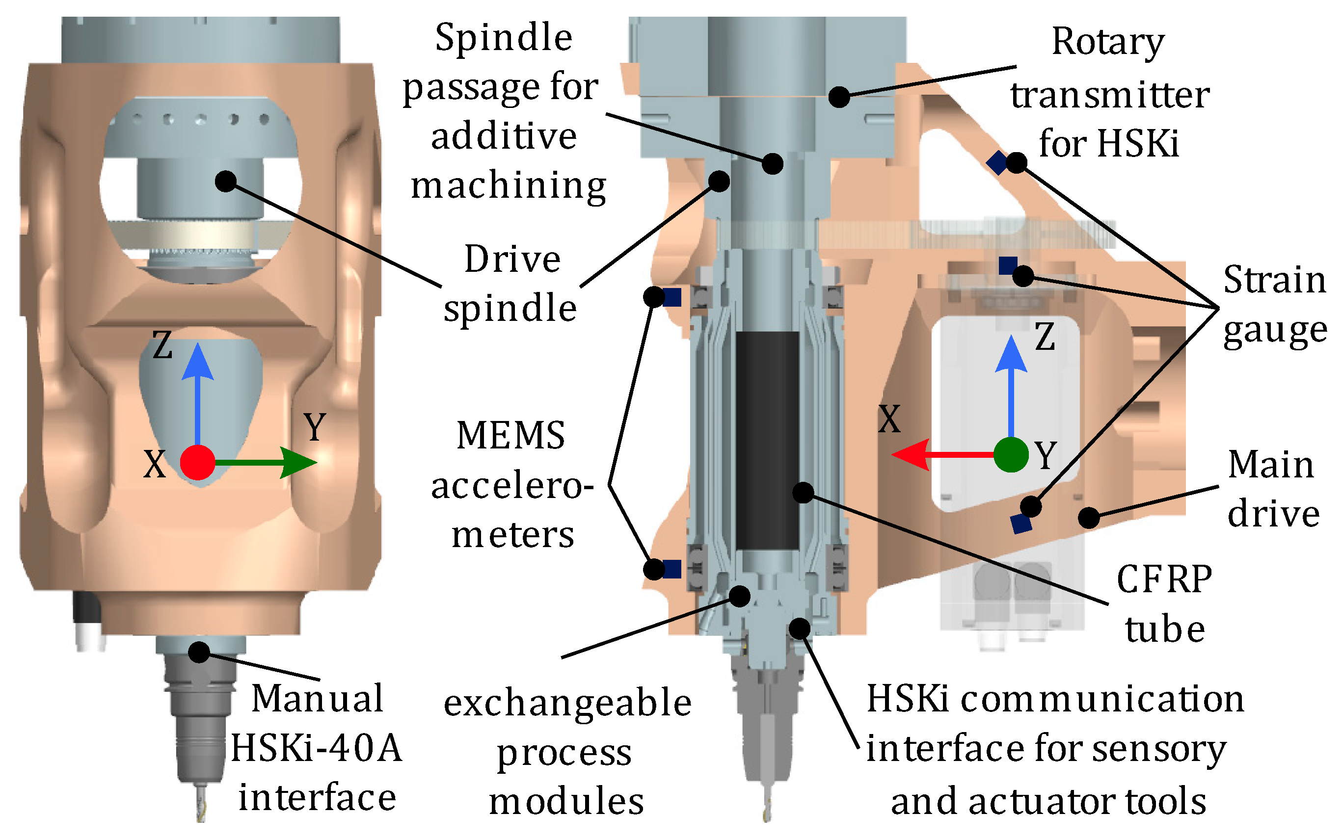
Figure 4 shows an end-effector (EE) that can adapt to the production-related requirements of a product and map various manufacturing processes in the additive–subtractive process chain. Furthermore, the EE can use integrated sensors and intelligent tools and components to record its status and use the data obtained by the actuators to counteract process deviations, e.g., drifting of the milling cutter or unwanted vibrations.
To determine which parameters the multi-process EE must have, a virtual process kit is created that selects the necessary processes based on the product to be manufactured. For this purpose, a comprehensive solution space consisting of various process modules and their technological properties will be defined. Technologies such as FDM three-dimensional (3D) printing, milling, joining, and gripping are considered. A characteristic parameter field describes the solution space, including power, speed, and gripping range. Furthermore, the capability characteristics of the process modules, including the material spectrum, accuracy, and stiffness, are presented in detail.
A central aspect of this work package is the abstraction of the processes using metadata to enable software-controlled selection, configuration, and combination of the process modules in the virtual solution space. This includes the definition of process chain configurations that consider the requirements of the individual technologies and the process combinations that can be realized and excluded.
Another focus is the conception, design, and construction of a multi-process-capable EE. This involves analyzing how the various process modules interact with each other and what effects these interactions have on the geometry, surface, and edge zone of the component.
The integration of sensor technology is being analyzed to complete the digital image of the processes. Sensors serve as a source of information to enable precise and comprehensive data acquisition, which is essential for software-driven process control. These investigations are intended to create a solid basis for developing flexible and adaptable manufacturing processes that meet the increasing demands for precision and efficiency.
3.4. Machine Kit
The process requires a suitable MRMT designed to autonomously adapt its configuration based on process requirements, specifically workspace, process forces, and chatter. The demonstrator, as shown in
Figure 5, provides this flexibility. It achieves this flexibility by utilizing a modular setup consisting of interchangeable machine axes connected through standardized interfaces. This modular design allows the machine to adjust its kinematic and dynamic properties to meet the specific demands of each manufacturing task, enabling highly versatile production.
The demonstrator can reconfigure itself by selecting and combining different axes based on the task trajectory and the process forces involved. For example, the workspace can be adjusted via length-adaptable axes to match the product’s size, eliminating the need to oversize the machine for future requirements. Unused axes are stored in a designated area for swift changes, minimizing downtime during reconfigurations.
The demonstrator features a customizable frame with a working area of 1.3 by 1.3 m, and it includes essential components such as safety housing, control electronics, and human–machine interfaces. It is designed to execute various manufacturing processes, including milling, FDM 3D printing, and joining, each requiring different machine configurations. The milling operations require a robust machine configuration. Here, the heavy-duty axes are arranged as a reinforced gantry structure that ensures enhanced rigidity, which is crucial due to the significant forces encountered during milling. Furthermore, milling may induce chatter into the system due to process forces exciting the machine structures’ natural frequencies. To reduce the chatter, a module to shift the natural frequencies of the structure has to be designed. Verification and validation of simulation models are discussed in this paper. Three approaches to deciding model validity are described, two paradigms that relate verification and validation to the model development process are presented, and various validation techniques are defined. Conceptual model validity, model verification, operational validity, and data validity are discussed. A way to document results is given, and a recommended procedure for model validation is presented.
The additive FDM process does not necessitate high rigidity but instead benefits from agile and dynamic machine movements. A lightweight kinematic structure is optimal for this process, enabling rapid and efficient production dynamics. This lightweight kinematic structure also benefits from machine axes with high acceleration profiles, such as belt-driven axes, which are selected for this process. Another consideration is the workspace, where state-of-the-art machines have a fixed workspace and, therefore, have to be designed for the largest possible future product. This demonstrator can adapt its workspace to the product via length-adaptable feed axes. Concepts for such length-adaptable feed axes are shown in
Figure 6.
Kinematic parametrization refers to modifying the physical movement and configuration of machine components to adapt to different production needs, such as product sizes. To deal with such changing requirements, two main approaches are considered. The first is “growing” axis systems, such as telescopic mechanisms, which allow machines to adjust their size automatically and facilitate continuous production without manual intervention. Another approach utilizes extendable modular systems that, while requiring manual setup, are simpler in design and easier to implement. Such systems might include technologies like linear direct drives or pinion drives, which can be adjusted to suit the specific dimensions needed for different tasks.
Dynamic parametrization focuses on modifying the mechanical properties, such as stiffness and damping, of machine components to optimize their performance under different operational conditions. This capability is essential for maintaining high precision and stability in production, particularly when dealing with varying process forces and speeds. As illustrated in
Figure 7, one possible approach is to improve the dynamic properties by developing adaptive stiffness modules that can change their stiffness by pre-loading springs using an actuator. This technique improves the dynamic stiffness of the machinery, which is crucial for processes requiring high precision, like milling. Another module, which is placed between the ball screw drive and spindle, could also be used to change the stiffness of the structure.
Furthermore, safety measures such as protective housings and sensors are integral to the setups, ensuring a secure production environment. These systems also have to be modular to ensure safety when switching between different axis configurations. The final demonstrators should then be able to showcase the flexibility and adaptability of modular machine tool systems by covering a wide range of machine kinematics and dynamics.
3.5. Potential Use Case: Product Configurator and Exemplary Product
To validate the novel manufacturing process, a modularized electrical machine, specifically an axial flux machine, is used as a potential product to be manufactured by SVPS. The modularization principle divides the various zones of the axial flux machine into modules, thereby reducing the manufacturing difficulty [
57]. Unlike conventional radial flux machines, the axial flux machine has a disk-shaped air gap, which allows geometrically uniform sub-segments to be axially stacked, even with multiple air gaps [
58]. This modular approach allows flexible customization of performance and installation space, which is critical for early testing of the new manufacturing process.
Defined modules for the axial flux machine include the bearing shield (front and back), shaft segment, housing segment, rotor disc (outer and inner), and stator ring, each with increasing tolerances and complexity. Initial testing should focus on simple modules such as the housing segment and bearing shields, which require additive and subtractive manufacturing steps to achieve precise tolerances. As development progresses, increasingly complex modules and finished products should be tested, with flexible interfaces supporting autonomous manufacturing steps. The first design of such an axial flux machine, showing the mentioned modules, is given in
Figure 8.
In addition, a product configurator enables the alignment of functional requirements with design implementation and helps model and evaluate interactions between product design and manufacturing processes. The first implementation of such a product configurator for the axial flux machine is shown in
Figure 9. This tool facilitates functional modeling, highlights where human approval is required, and identifies autonomous adjustments to optimize production. By guiding products from the requirements phase to production, the configurator plays a key role in leveraging SVPSs for efficient, customizable manufacturing. Together, modular product design and the configurator support the development of adaptable, customer-focused production systems while maximizing the potential of SVPSs.
4. Discussion and Conclusions
This paper addresses the key challenge identified in the research gap: the need for a higher degree of automation in modular and reconfigurable machine tools, which are currently reconfigured manually. We have laid a solid foundation by developing the framework, software, and hardware tools necessary to enable autonomous reconfiguration in MRMTs. The SVPS integrates the Digital Twin, process simulations, and modular, reconfigurable systems to enable a fully automated process flow from product requirements to manufacturing, with the option for a complete loop via feedback of process data via automated quality assurance, which was not considered here.
Many of the work steps presented are already covered individually in the literature and represent only limited progress in themselves. The main innovation of this paper is the linking of these work steps into a continuous workflow in which the individual subsystems are aligned with each other, whereby a uniform data transfer represents a major challenge. Since this paper represents the conceptual idea of the principle of SVPSs and the transfer along the work steps that currently still requires manual work, further work is necessary for a fully automated process. The verification for industrial use requires validating the overall requirements of the digital chain through system-level integration tests and verifying and qualifying the classification of individual sub-modules. These processes are based on the electrical machine described in
Section 3.5. While recognized as critical, these verifications have not yet been carried out and will rely on experimental data for completion, which is currently being worked on.
Nevertheless, the workflow shown and the SVPS concept demonstrate the potential for a reconfigurable machine. The SVPS provides a flexible, adaptable production environment that reduces time-to-market and lowers engineering costs for new products or changes. However, in order to fully realize autonomous reconfiguration, further research is required, as mentioned above. This includes advances in the areas of software-defined control systems, autonomous calibration, system modeling, adaptive machine components, and seamless integration of quality assurance and product configuration.


 ,
, 