Article

Calculation Model for Multi-Roller Load Distribution of Planetary Threaded Roller Bearings Considering Machining Errors

College of Mechanical and Electrical Engineering, Northeast Forestry University, Harbin 150040, China
*
Author to whom correspondence should be addressed.
Machines 2025, 13(1), 26; https://doi.org/10.3390/machines13010026
Submission received: 9 December 2024 / Revised: 31 December 2024 / Accepted: 1 January 2025 / Published: 3 January 2025
(This article belongs to the Section Advanced Manufacturing)

Abstract

:
Load-bearing capacity is critical in planetary threaded roller bearings (PTRBs). Machining errors cause uneven load distribution coefficients (LDC) among the rollers and the threaded teeth. The limited literature explores the influence of machining errors on PTRB’s load-bearing performance. A computational model that considers multiple machining errors when determining the load distribution among the rollers and the threaded teeth is proposed in this paper. The PTRB is discretized into a multi-roller spring system. Moreover, a set of nonlinear equations is established based on deformation coordination and force balance. The theoretical model is verified against the finite element simulation results and previous studies. The influence of machining errors on the LDC among the rollers and the threaded teeth is investigated. Results indicate that pitch errors do not significantly impact the LDC among the rollers. However, pitch errors directly affect the LDC among the threaded teeth. Errors in roller nominal diameter and the eccentricity of the inner and outer ring axes cause uneven LDC among the rollers; axis misalignment has a complex effect on the LDC. The proposed computational model can guide the parameter design, component processing, and assembly method of PTRB.

1. Introduction

Rolling bearings play a crucial role in rotating machinery [1,2]. Compared to angular contact ball bearings and cylindrical roller bearings, Planetary Thread Roller Bearings (PTRBs) exhibit higher power density, greater load-carrying capacity, and lower friction torque [3]. PTRBs mainly comprise an inner ring, rollers, an outer ring, and a cage, as shown in Figure 1. The inner and outer rings are made of external and internal threads with multiple annular threads; both threads are characterized by triangular tooth profiles. On the other hand, the rollers are equipped with annular threads that have arc-shaped tooth profiles. The rollers are evenly distributed along the circumference of the inner ring and held in place by the cage. The external load is distributed among the rollers via multiple rollers as the load-bearing elements, enhancing the load-carrying capacity. However, similar to Ball Screw Mechanisms (BSM) and Planetary Roller Screw Mechanisms (PRSM), PTRBs experience an uneven load distribution coefficient (LDC) among thread teeth due to cumulative deformation of the shaft segments [4,5,6,7]. In addition, recent studies [8,9] have indicated that machining errors result in unequal loads on each roller. This uneven distribution can limit the ultimate load-carrying capacity of PTRBs, accelerate wear, and reduce service life [10]. Therefore, considering the impact of machining errors on the LDC and exploring the relationship between machining errors and LDC is crucial for improving the load performance of PTRBs.
The development of PTRBs is still in its early stages, with only a few researchers investigating load distribution and friction torque. However, research on PRSMs can be used due to the structural similarity between PTRBs and PRSMs. Ryś and Lisowski [11] treated the deformation of PRSM components as rectangular volumes subjected to shear stress, establishing a load distribution model for PRSM. Abevi et al. [12] equated each part of PRSM to bars, beams, and a nonlinear spring and explored the influence of roller bending deformation on the load rate. Jones and Velinsky [13] linearized the Hertzian contact stiffness between the thread tooth contact points of PRSM. Furthermore, the authors developed a single-dimensional simplified equivalent spring network model. They derived the linear stiffness of PRSM components and used the direct stiffness method to compute the LDC. Zhang et al. [14] combined deformation coordination theory with force balance to develop a model of load distribution for PRSM by considering installation configuration, load conditions, and thread shape parameters.
Most of the aforementioned load distribution models do not consider the impact of machining errors. When such errors are factored in, the calculation of load distribution becomes more complex. Zhang et al. [15] experimentally observed a clear relationship between thread wear and lead deviation. The authors indirectly indicated that the influence of errors such as lead deviation cannot be ignored when establishing load distribution models. It should be noted that the abovementioned models assume uniform LDC among the rollers, which is not the case in reality. Du et al. [8] considered radial loads and machining errors and established a load distribution model. The results showed that LDC among rollers varies under radial loads, while the contact force exhibits periodic variation. Fu et al. [16] accounted for position errors and thread index errors. The authors discretized the PRSM into a multi-roller spring system. They established a static model for load distribution under axial load with errors. This model demonstrated that screw and nut position errors greatly impact uneven LDC among rollers more than roller position errors. Moreover, the abovementioned errors significantly affect PRSM stiffness. Hu et al. [9] developed a PRSM load distribution model that considered pitch errors, roller nominal diameter errors, and eccentricity errors of the screw and nut. Experimental measurements of machining errors showed that pitch errors cause variations in the axial contact load of individual roller threads. However, such errors have a limited impact on the LDC among rollers. In contrast, the eccentricity errors of the nut have the greatest impact on the LDC among rollers, followed by the screw shaft deviation.
Research on PTRBs is still in its infancy phase. Zheng et al. [17] derived theoretical models for the basic axial-rated load, basic radial-rated load, and friction torque of PTRBs. The authors analyzed the influence of different structural parameters on PTRB performance. Ni et al. [18] established a static stiffness model of PTRBs. The authors calculated the deformations of thread teeth, contact areas, and shaft segments of components. Lastly, they obtained the LDC of PTRBs based on deformation coordination. Xie et al. [19] adopted the direct stiffness method to discretize PTRBs, establishing a single-dimensional equivalent spring network model and deriving a contact load distribution model for PTRBs. Zheng et al. [20] solved the elastic deformation of each contact component under axial and radial loads using spatial meshing and Hertzian contact theory. The authors proposed a model based on compatibility equations to calculate the LDC of PTRBs. The results indicate that adjusting thread pitch and increasing the number of rollers can improve the LDC.
The aforementioned studies on PTRB thread tooth load distribution were conducted without considering machining errors and assuming that all rollers bear the same load. Although these assumptions simplify the problem and reduce the computational workload, they significantly differ from the actual working conditions. Therefore, this paper proposes a load distribution model for PTRB thread teeth that considers multiple machining errors to explore the load-carrying characteristics of PTRBs. In addition, it needs to be clarified that the heavy-duty PTRB proposed in this paper is primarily used in the supporting structure of the rotating components of electric cylinders [21]. During its operation, it mainly withstands significant axial loads. Therefore, this paper does not consider the impact of radial loads on the load distribution.
This model calculates the LDC among the rollers and thread teeth of PTRBs. First, a PTRB coordinate system is established, and the rollers are numbered. Then, a model for axial clearance calculation considering machining errors is developed based on the theory of spatial meshing of two curved surfaces. The equivalent contact force and deformation are calculated via the compression distance and axial clearance model. The PTRB is discretized into a multi-roller spring system. Next, a nonlinear system of equations for thread tooth contact load is established based on deformation coordination, force balance equations, and an existing axial stiffness model. A flowchart of the calculation process is provided. The proposed model is verified via the finite element analysis and the existing literature, yielding the thread tooth load distribution for PTRBs under error-free and error conditions. Finally, a case study is conducted to investigate the relationship between machining errors and the LDC among PTRB rollers.

2. Model

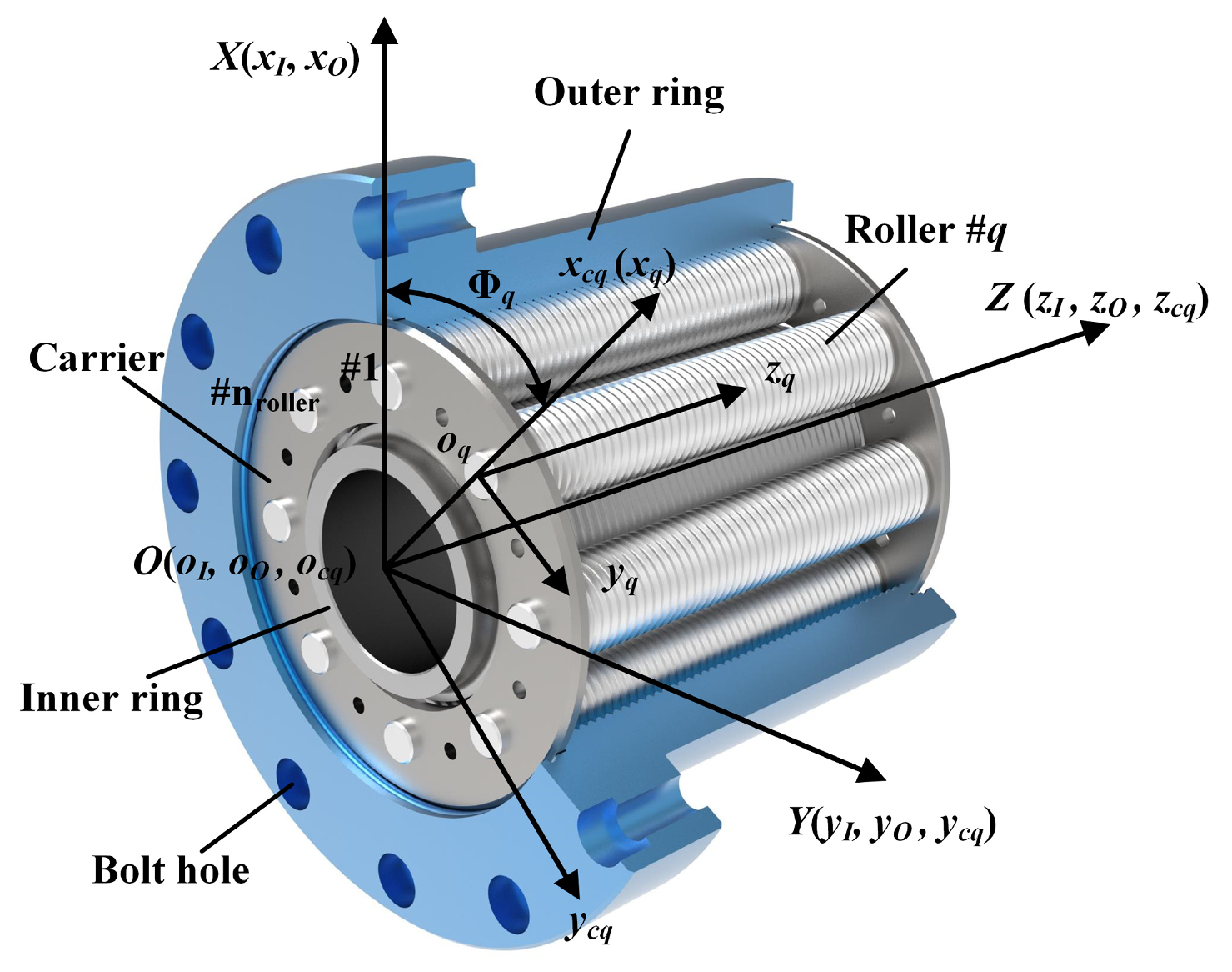
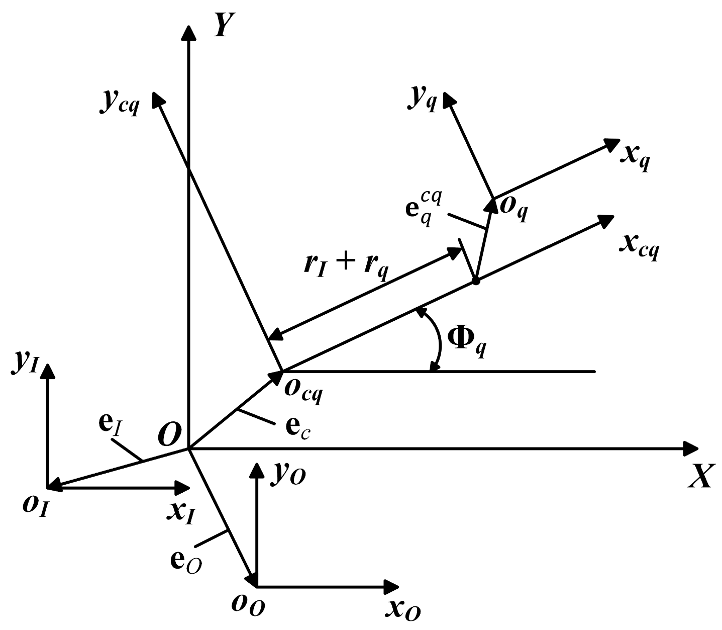
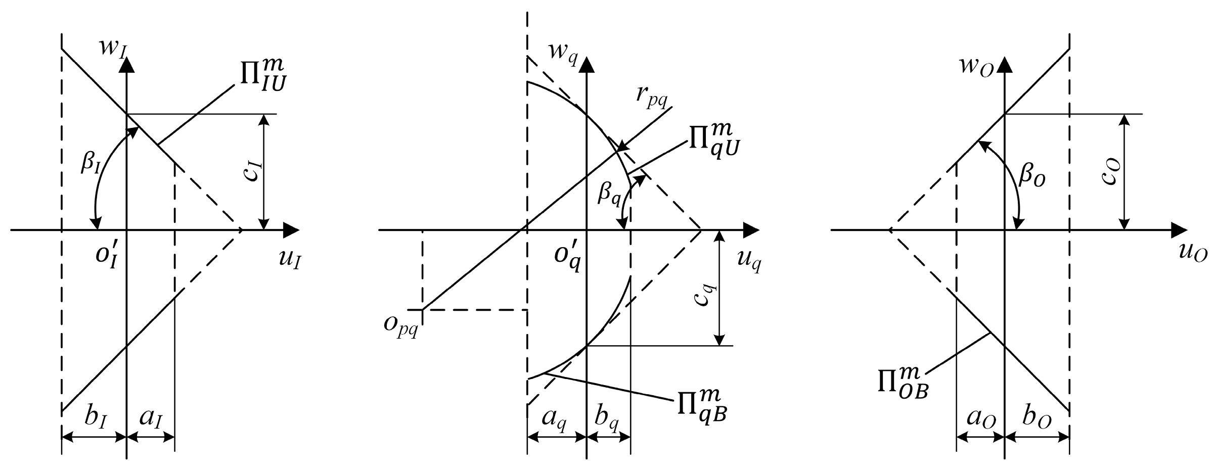
2.1. Establishing the Coordinate Systems for PTRB

A coordinate system is established based on the structural characteristics of the PTRB, as shown in Figure 1. This system comprises five coordinate systems describing the positions of PTRB components used to calculate axial clearance. Each roller in Figure 1 is numbered, and the following coordinate systems are defined: Global coordinate system σ [ O ; X ; Y ; Z ] , with its Z-axis coinciding with the PTRB’s central axis, Local coordinate system σ I [ o I ; x I ; y I ; z I ] , connected to the inner ring, and coordinate system σ O [ o O ; x O ; y O ; z O ] , connected to the outer ring. These three coordinate systems ideally overlap, avoiding the need for coordinate transformations. Coordinate system σ c q [ o c q ; x c q ; y c q ; z c q ] describes the circumferential position of the q-th roller relative to the inner ring. Its zcq axis coincides with the Z-axis of the global coordinate system, while the xcq axis points to the axis of the q-th roller. The coordinate system σ q [ o q ; x q ; y q ; z q ] is connected to the q-th roller, with its zq axis coinciding with the roller’s axis and pointing in the same direction as the global Z-axis. In contrast, the xq axis coincides with the xcq axis in system σ c q [ o c q ; x c q ; y c q ; z c q ] .
The phase angle Φ q of the q-th roller can be expressed by the following formula:
Φ q = Φ 0 + 2 π q 1 / n r o l l e r ,
where Φ 0 is the angle between the first roller and the global X-axis, and q is the serial number of the roller, where q = 1 , 2 , , n r o l l e r and n r o l l e r represents the total number of rollers.

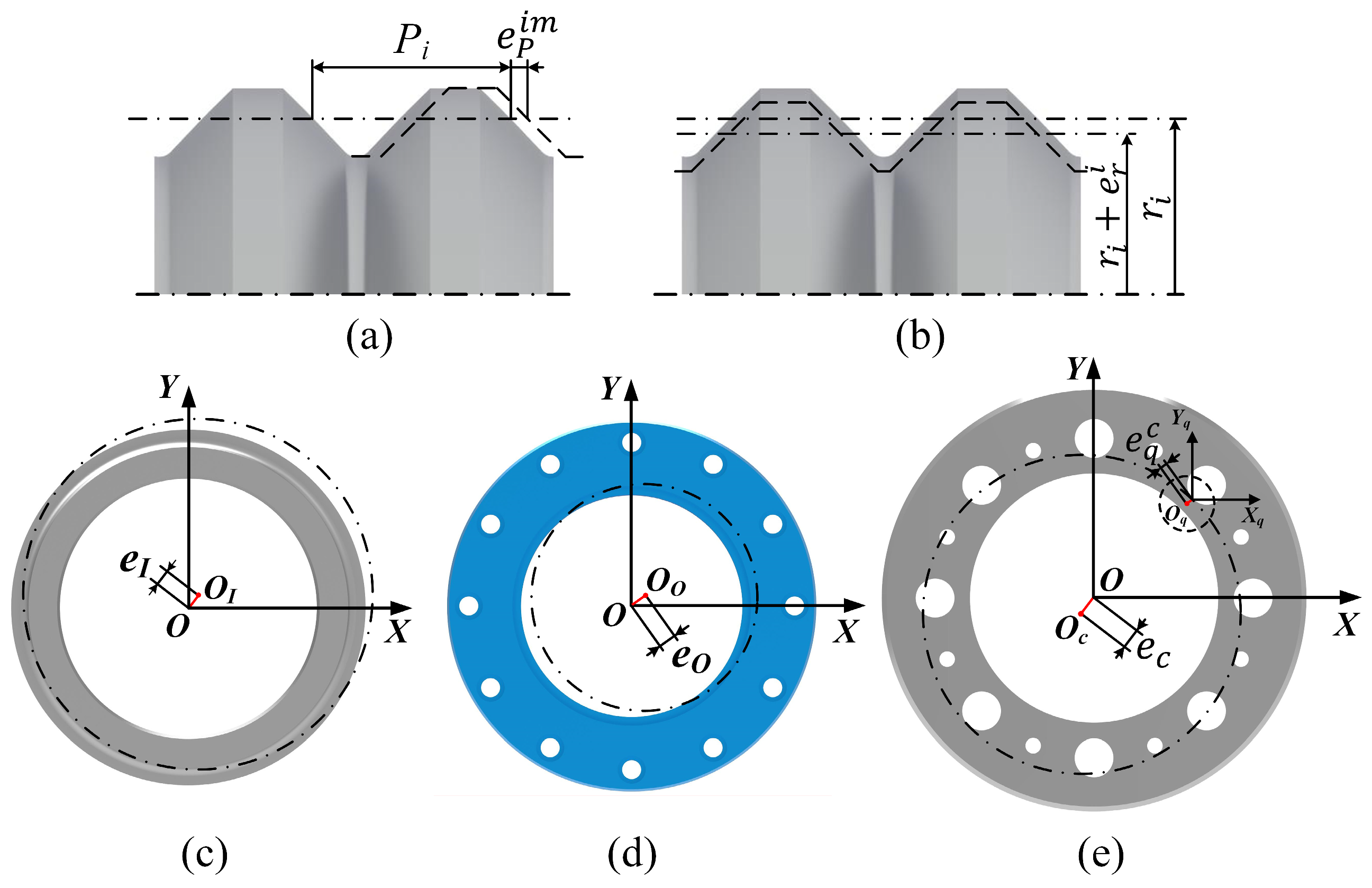
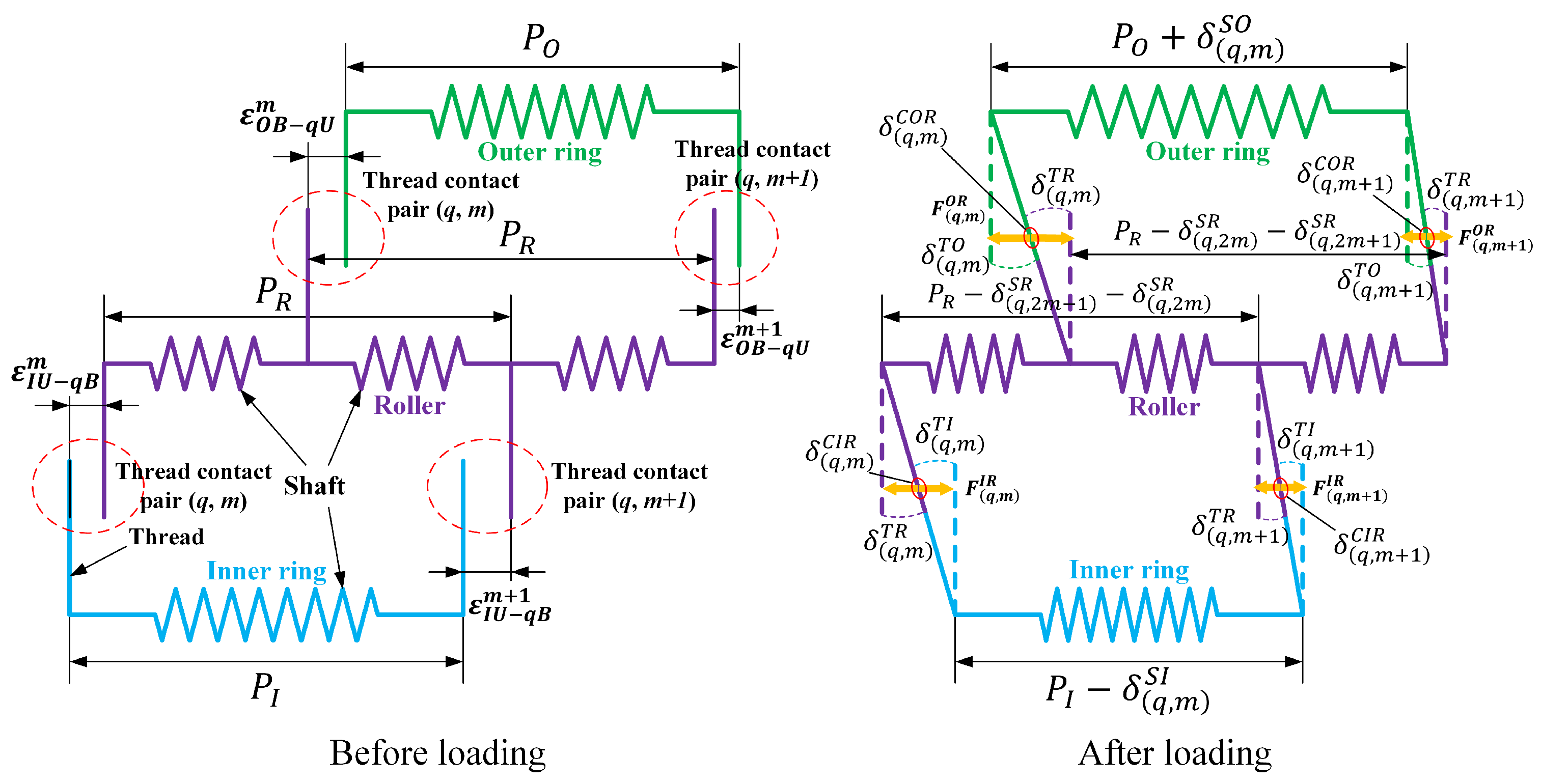
2.2. PTRB Axial Clearance Model Considering Manufacturing Errors

The primary manufacturing errors affecting the LDC and bearing capacity, including pitch errors, nominal diameter errors, and axis misalignment of the inner and outer rings and rollers, are shown in Figure 2. Furthermore, since the impact of thread profile angle errors on load distribution is minimal [15], thread angle deviation is not considered in this paper.
As shown in Figure 2a, e P i m i = O , I , q represents the pitch error of the m-th thread teeth on the outer ring, the inner ring, and the q-th roller, respectively. It represents the deviation between the actual pitch and the theoretical pitch, mainly caused by the axial feed deviation of the cutting tool. Figure 2b, e r i i = O , I , q represents the nominal diameter error of the outer ring, the inner ring, and the q-th roller, respectively. It represents the deviation between the actual nominal diameter and the theoretical nominal diameter, primarily caused by the radial feed deviation of the cutting tool. Lastly, the axial concentricity error of each part is shown in Figure 2c–e. It indicates the deviation between the axis of the thread raceway and the part’s reference axis, mainly caused by the clamping errors during machining. Additionally, it is assumed that all parts have smooth surfaces, meaning that the impact of surface roughness on load distribution is not considered in this paper.
Axis misalignments of the inner ring, outer ring, and rollers are illustrated in Figure 3, Parameters e q c q represent the axis error of the q-th roller in the local coordinate system σ c q [ o c q ; x c q ; y c q ; z c q ] . Parameters r I and r q represent the nominal diameters of the inner ring and the q-th roller, respectively.
The axis misalignment vector of the q-th roller in the global coordinate system σ [ O ; X ; Y ; Z ] is represented as follows:
e q = H q r I + r q , 0 , 0 T + e q c q + e c ,
where H q is the rotation matrix expressed as follows:
H q = cos Φ q sin Φ q 0 sin Φ q cos Φ q 0 0 0 1 .
The axial error vector e q c q for the q-th roller in the local coordinate system σ c q [ o c q ; x c q ; y c q ; z c q ] and axis error vector e c for a local coordinate system σ c q [ o c q ; x c q ; y c q ; z c q ] in global coordinate system σ [ O ; X ; Y ; Z ] can be expressed as follows:
e q c q = e q x , e q y , 0 T
e c = e c x , e c y , 0 T
where e q x , e q y , e c x , and e c y are the x-direction and y-direction components of the vectors e q c q and e c in the corresponding coordinate system, respectively.
Axis misalignments of the inner and outer rings e I and e O can be expressed in the global coordinate system as follows:
e I = e I x , e I y , 0 T ,
e O = e O x , e O y , 0 T .
When no external load is applied, manufacturing errors may increase or decrease the distance between the mating surfaces, causing uneven contact among rollers. Therefore, the axial clearance model is required to analyze the uneven LDC.
The axial load can be applied on the same side or opposite sides of the bearing. The same-side loading scenario is explored in this study. Figure 4 shows the axial clearance between the threaded surfaces in this scenario. In Figure 4, Π I U m and Π O B m denote the upper surface of the threaded teeth of the inner ring and the lower surface of the threaded teeth of the outer ring, respectively. These surfaces are mated with the m-th threaded tooth of each roller, where m = 1 , 2 , , n T and n T is the total number of threaded teeth of a single roller. In addition, the upper and lower surfaces are the higher and lower z-coordinate values of the two sides of the threaded teeth, respectively. Parameters Π q U m and Π q B m denote the upper and lower surfaces of the m-th threaded tooth of the q-th roller, respectively. In addition, ε O B q U m is the axial clearance between the threaded surfaces Π O B m and Π q U m , while ε I U q B m is the axial clearance between the threaded surfaces Π I U m and Π q B m .
The cross-sectional thread profiles on the inner ring, outer ring, and rollers are illustrated in Figure 5 [22].
Considering machining errors, the four thread surfaces, Π I U m , Π q U m , Π q B m , and Π O B m can be expressed in the global coordinate system σ [ O ; X ; Y ; Z ] as follows:
R I U m = u I + r I + e r I cos θ I u I + r I + e r I sin θ I c I u I tan β I + m 1 P + m = 1 m e P I m + e I ,
R q U m = H q u q + r q + e r q cos θ q u q + r q + e r q sin θ q w p q + r p q 2 u q u p q 2 + m 1 2 P + m = 1 m e P q m + r I + r q cos Φ q r I + r q sin Φ q 0 + e q ,
R q B m = H q u q + r q + e r q cos θ q u q + r q + e r q sin θ q w p q r p q 2 u q u p q 2 + m 1 2 P + m = 1 m 1 e P q m + r I + r q cos Φ q r I + r q sin Φ q 0 + e q ,
R O B m = u O + r O + e r O cos θ O u O + r O + e r O sin θ O c O + u O tan β O + m P + m = 1 m 1 e P O m + e O ,
where u i and θ i i = O , I , q represent the surface coordinates of the outer ring, inner ring, and the q-th roller, respectively. Parameters r i , β i , and c i i = O , I , q denote the nominal radius, flank angle, and half-tooth thickness of these components, respectively. Parameter P refers to the pitch of the threads, while u p q , w p q are the coordinates of the center of the circular arc profile of the roller thread, with r p q representing the arc radius.
u p q = r p q sin β q ,
w p q = r p q cos β q + c q .
According to the surface meshing theory [23], the following meshing equations can be established for the threaded tooth contact pair between the outer ring-roller side and the inner ring-roller side on the m-th threaded tooth of the q-th roller:
R O B m x = R q U m x R O B m y = R q U m y R O B m z = R q U m z + ε O B q U m n O B m × n q U m = 0 ,
R I U m x = R q B m x R I U m y = R q B m y R I U m z = R q B m z ε I U q B m n I U m × n q B m = 0 ,
where [ R ] x , [ R ] y , and [ R ] z denote the x, y, and z coordinates of the corresponding surface equations, respectively, while vector n is the normal vector of the corresponding surface [24].
The normal vector n I U m of the surface R I U m is
n I U m = tan β I + e β Im cos θ I tan β I + e β Im sin θ I 1 .
The normal vector n O B m of the surface R O B m is
n O B m = tan β O + e β O m cos θ O tan β O + e β O m sin θ O 1 .
The normal vectors n q U m and n q B m of the surfaces R q U m and R q B m can be expressed as follows:
n q U m = u q u p q cos θ q + Φ q r p q 2 u q u p q 2 u q u p q sin θ q + Φ q r p q 2 u q u p q 2 1 ,
n q B m = u q u p q cos θ q + Φ q r p q 2 u q u p q 2 u q u p q sin θ q + Φ q r p q 2 u q u p q 2 1 .
The contact point coordinates and axial clearance can be solved by substituting surface equations that consider errors in normal vectors for each surface into Equations (14) and (15).

2.3. Equivalent Contact Force and Contact Deformation

The machining error can alter the axial clearance between the contact points of the thread teeth, affecting the contact deformation of the corresponding thread teeth and redistributing the load on the threads. Therefore, it is necessary to calculate the contact deformation of thread teeth according to the axial clearance caused by the machining error, and finally obtain the load on each roller. The detailed calculation process is as follows [9]:
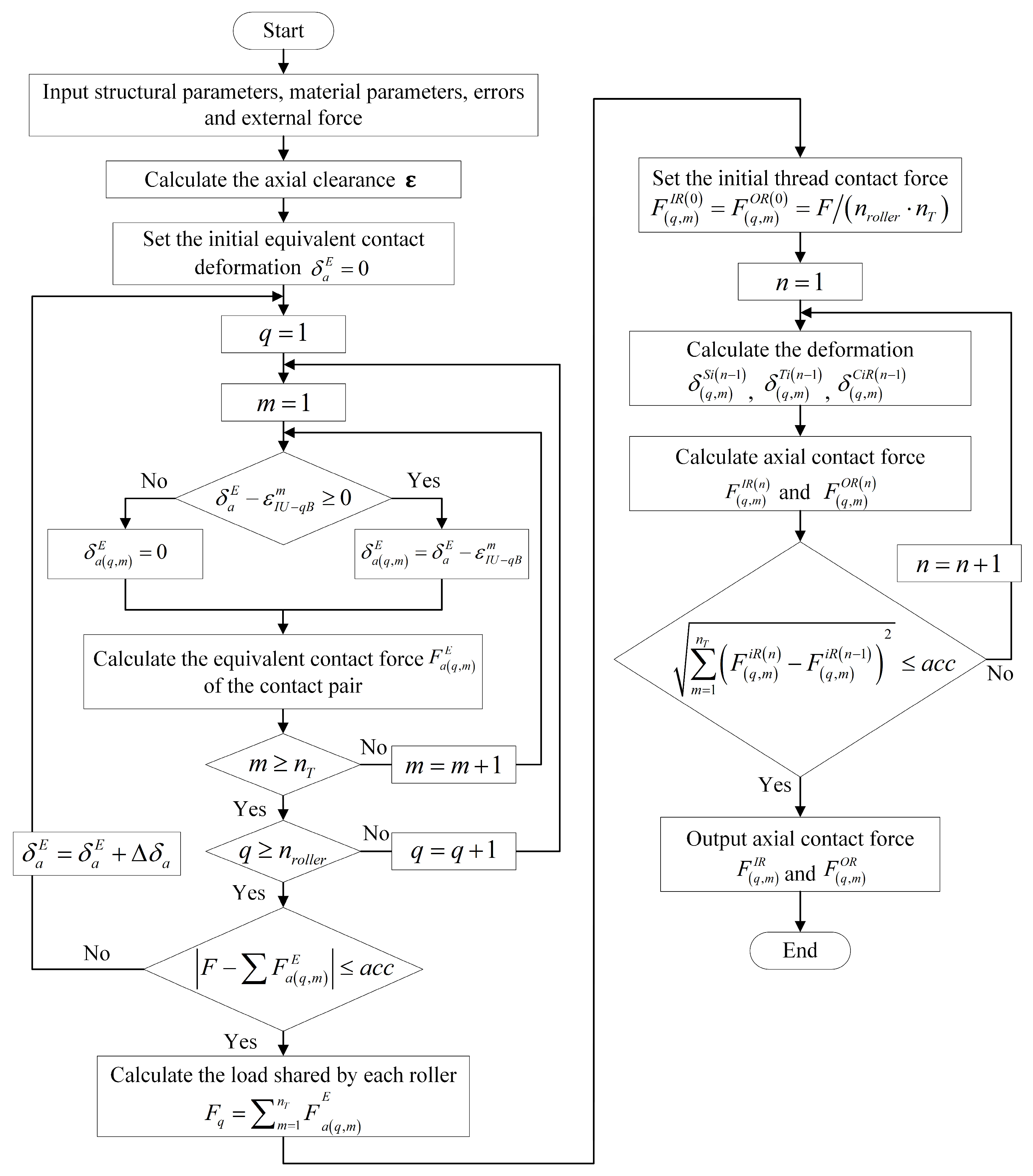
  • The equivalent contact deformation is set to zero. A step size for contact deformation iteration is introduced, and appropriate calculation precision is established. In this study, an iteration step size of Δ δ a = 1 × 10 9 mm and a calculation accuracy of a c c = 10 5 F are used in MATLAB 2021b to ensure result convergence while maintaining a reasonable balance between calculation speed and acceptable accuracy.
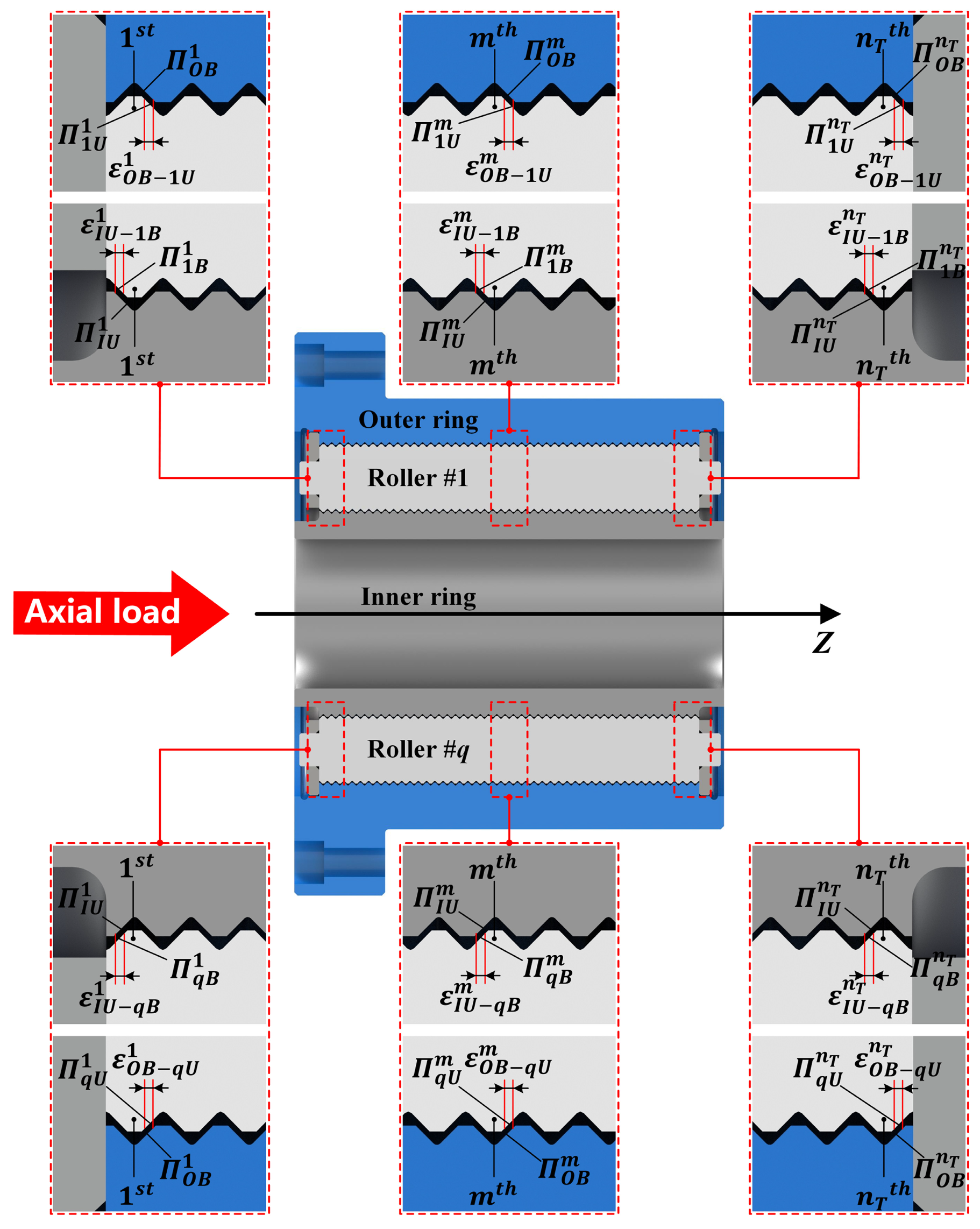
  • The equivalent contact deformation is computed by considering the machining error. Machining error causes variations in the axial clearance of meshing thread teeth, resulting in different contact conditions among the threads. Therefore, determining whether thread teeth are in contact based on the following conditions is essential (the inner ring-roller side is taken as an example; the same rules apply to the outer ring-roller side):
    • If δ a E ε I U q B m < 0 , the preset equivalent contact deformation is insufficient to eliminate the axial clearance between the m-th thread tooth of the q-th roller. In other words, the two corresponding thread teeth have not yet made contact, and the thread tooth is in a non-contact state. The equivalent contact deformation of the corresponding thread tooth is δ a ( q , m ) E = 0 .
    • If δ a E ε I U q B m 0 , the axial clearance between the m-th thread tooth of the q-th roller is fully eliminated, resulting in contact. The thread tooth is now in contact mode, and its equivalent contact deformation is δ a ( q , m ) E = δ a E ε I U q B m .
  • The equivalent axial contact force is calculated. It can be calculated by the following formula [8]:
F n E = δ n E K 3 / 2 ,
where K is the equivalent contact stiffness, which can also be calculated by the formula given in the reference [8].
4.
A check is performed to see whether the calculation precision has been met.
  • If F F a ( q , m ) E a c c , the calculation precision is satisfied. The equivalent contact force is output as the corresponding thread tooth’s equivalent contact load.
  • If F F a ( q , m ) E > a c c , the precision is not satisfied. In this case, the equivalent contact deformation is updated by adding the iteration step size. The updated equivalent deformation is returned for recalculation in steps 2 and 3. This process is repeated until the result satisfies the calculation precision.
The equivalent contact force for all threaded teeth can be obtained after completing the above calculation steps. Then, the load on each roller can be expressed as follows:
F q = m = 1 n T F a q , m E .

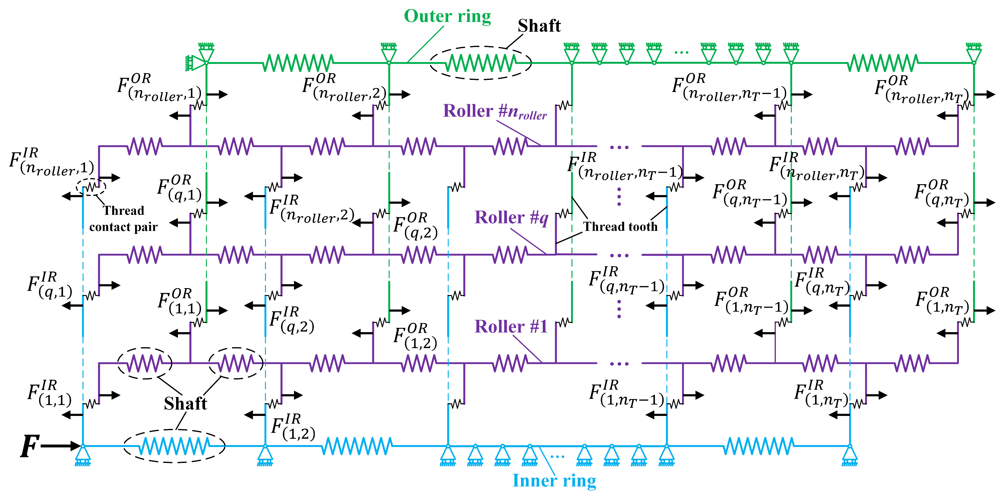
2.4. Calculation Model for PTRB Contact Load Distribution

As shown in Figure 6, a multi-roller spring system of the PTRB considering machining error is established. The LDC among the rollers is no longer uniform due to the machining error. The shaft section and the thread tooth contact pair of the PTRB are represented by springs. The thread tooth is simplified as a plate spring, as shown by the vertical line segments. An axial load F is applied to the first node of the inner ring to simulate the force conditions of the PTRB. All nodes are restricted to axial displacement to simulate the boundary conditions. Lastly, the first node of the outer ring is also fixed.
According to Figure 6, the axial load F ( q , j ) S I on the j-th shaft segment where the inner ring engages the q-th roller can be expressed as follows:
F q , j S I = F q m = 1 j F q , m I R         q = 1 ,   2 ,   ,   n r o l l e r ;   j = 1 ,   2 ,   ,   n T 1 ,
where F q is the axial load applied to the q-th roller and F ( q , m ) I R is the axial contact load between the inner ring and the m-th threaded tooth of the q-th roller.
Similarly, the axial load F ( q , j ) S O on the j-th shaft segment where the outer ring engages the q-th roller can be expressed as follows:
F q , j S O = F q m = 1 j F q , m O R         q = 1 ,   2 ,   ,   n r o l l e r ;   j = 1 ,   2 ,   ,   n T 1 ,
where F ( q , m ) O R is the axial contact load of the outer ring with the m-th threaded tooth of the q-th roller.
The threaded teeth of each roller engage the inner and outer ring’s threaded teeth. Therefore, axial load F ( q , j ) S R on the j-th shaft segment of the q-th roller can be expressed as the sum of the corresponding threaded teeth contact loads on the inner ring-roller side and the outer ring-roller side in the following form:
F q , j S R = m = 0 j / 2 F q , m I R F q , m O R + F q , j / 2 + 1 I R q = 1 , 2 , , n r o l l e r ;   j = 1 , 3 , , 2 n T 1 m = 0 j / 2 F q , m I R F q , m O R q = 1 , 2 , , n r o l l e r ;   j = 2 , 4 , , 2 n T 2 ,
where j / 2 is a downward rounding symbol indicating the largest integer lower than j / 2 .
The axial loads of the inner ring, roller, and outer ring’s axial segments are obtained. Then, the axial stiffness of the axial segments can be used to solve for the axial deformation of the corresponding axial segments. The axial deformation of each part of PTRB can be expressed by the following formula:
δ ( q , j ) S i = F ( q , j ) S i K i S       i = I , O , R ,
where K i S ( i = I , O , R ) is the axial stiffness, the calculation formula is given in the reference [14]. In addition to the axial deformation of the shaft segment, there are two other types of deformation in the PTRB: deformation of the thread teeth δ ( q , m ) T i ( i = I , O , R ) and deformation in the contact area of the thread teeth δ ( q , m ) C i R ( i = I , O ) . Similarly, the calculation formulas for both are provided in the references [20,25].
The deformation coordination conditions between two adjacent thread tooth contact pairs on the outer ring-roller and inner ring-roller sides are illustrated in Figure 7. Before loading, all components (except for the outer ring fixed in the housing) are in a free state, with initial axial clearances between the adjacent thread tooth contact pairs. The initial axial clearances among the thread teeth are not identical due to machining errors. Initial axial clearances on the inner ring-roller and outer ring-roller sides gradually diminish once the inner ring is loaded. A closed loop is formed by the two adjacent thread tooth contact pairs. Deformation occurs in the thread tooth contact area to counteract the external load. Even though the deformation varies due to structural dimensions and machining errors of all components, the thread tooth contact loop remains closed regardless of changes in external axial loads. This closed-loop condition ensures contact between the thread teeth. The deformation coordination process means that the deformation of two adjacent thread tooth contact pairs is coupled. Hence, the relationship can be described by the following equations.
If machining errors are considered, the deformation coordination relationship between the outer ring and the m-th threaded tooth contact pair of the q-th roller, i.e., the m-th closed loop on the outer ring-roller side, can be expressed as follows:
δ q , m T O + δ q , m T R + δ q , m C O R δ q , 2 m S R δ q , 2 m + 1 S R + ε O B q U m = δ q , m + 1 T O + δ q , m + 1 T R + δ q , m + 1 C O R + δ q , m S O + ε O B q U m + 1
Similarly, the m-th closed loop on the inner ring-roller side can be expressed as follows:
δ q , m T I + δ q , m T R + δ q , m C I R δ q , m S I + ε I U q B m = δ q , m + 1 T I + δ q , m + 1 T R + δ q , m + 1 C I R δ q , 2 m 1 S R δ q , 2 m S R + ε I U q B m + 1
In addition, the sum of the threaded tooth loads on the inner ring-roller side and the outer ring-roller side should satisfy the force balance equation as follows:
m = 1 n T F q , m i R = F q         i = I , O   ;       q = 1 ,   2 ,   3 ,   ,   n r o l l e r .
Since the contact stiffness of the thread teeth varies with contact deformation, an iterative method is used to solve the above nonlinear equations. The specific procedure is as follows:
  • The external axial load is assumed to be uniformly distributed among all thread teeth, with the initial contact load on each thread tooth being F / ( n r o l l e r n T ) .
  • The initial contact load is substituted into nonlinear equations to solve for the updated contact load and obtain the updated contact stiffness of the thread teeth.
  • The contact load for all thread tooth contact pairs is determined through iterative calculations, meeting the preset precision.
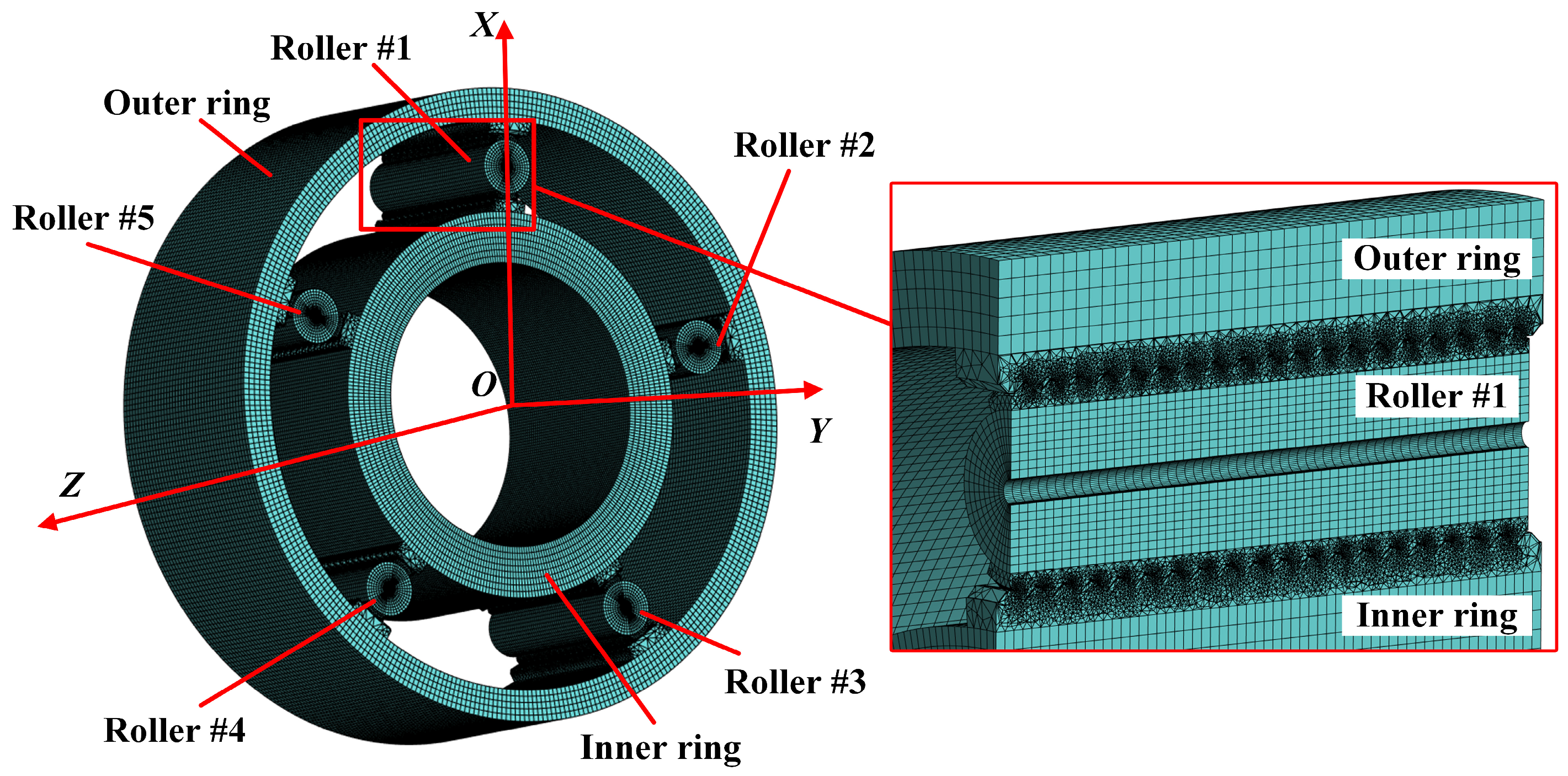
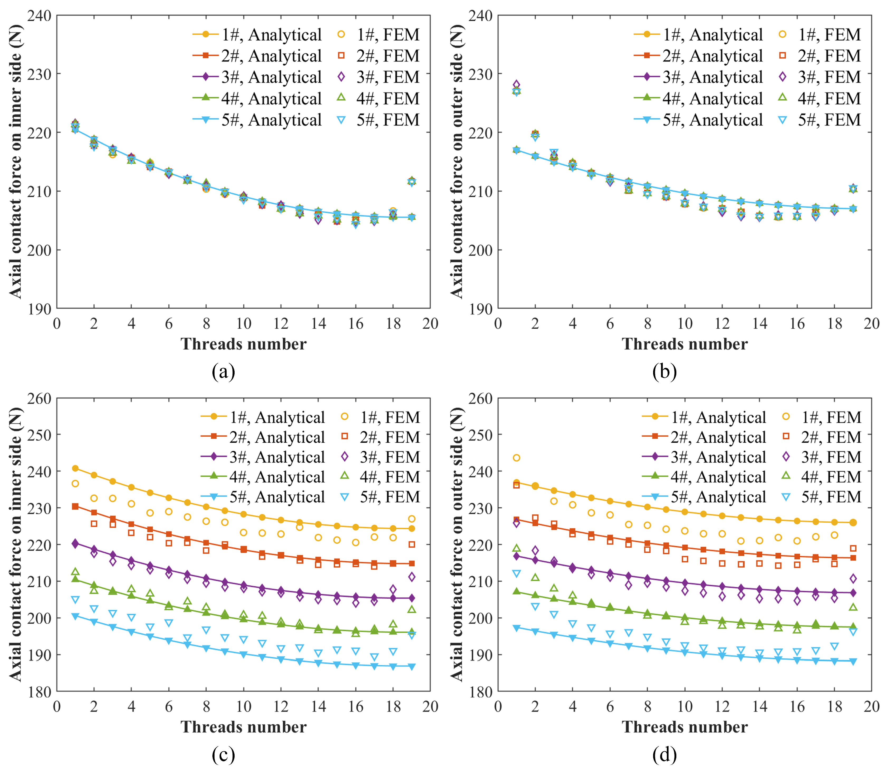
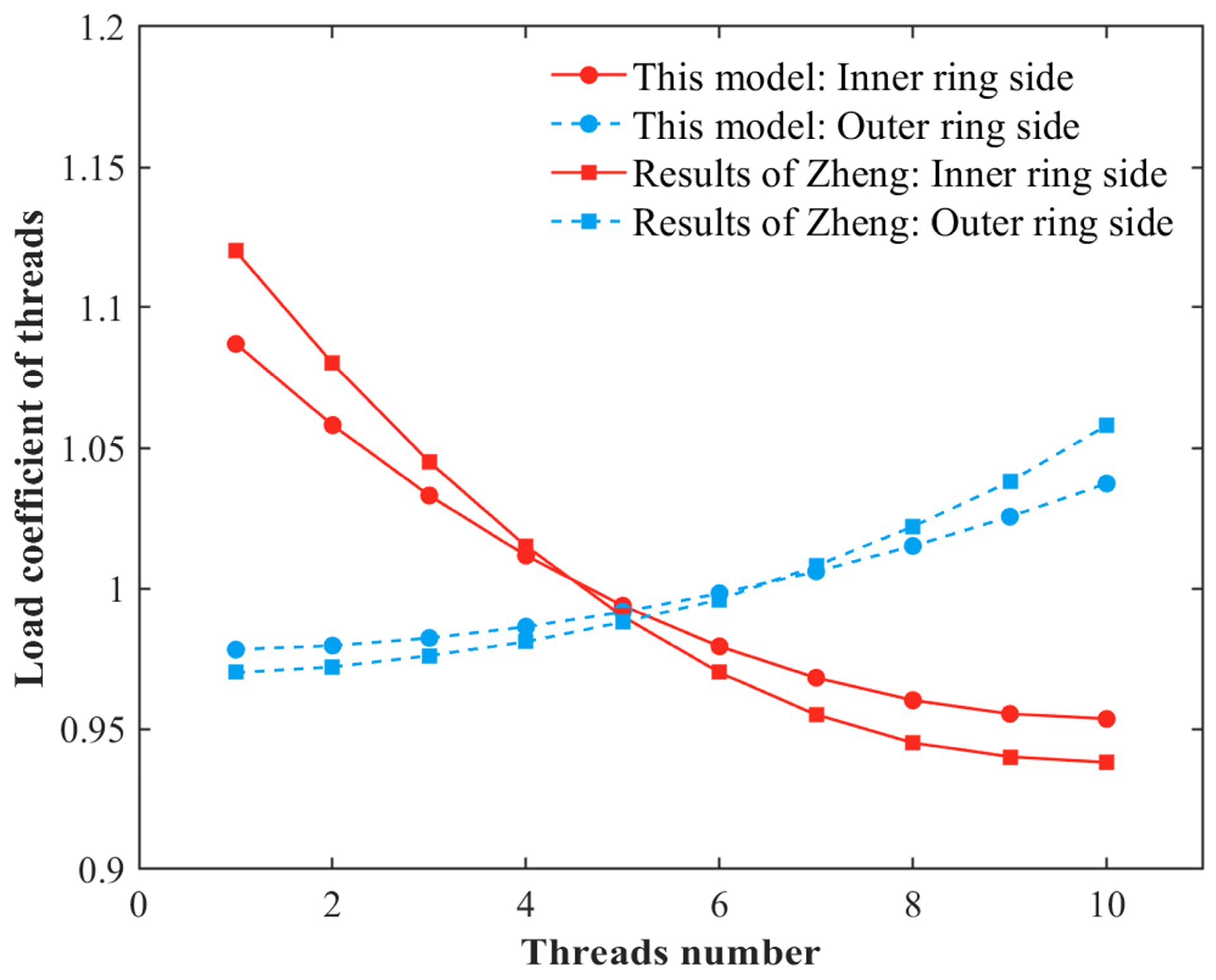
The specific calculation process is shown in Figure 8.

3. Model Validation

In this section, the accuracy of the proposed calculation model is verified through comparison with static finite element analysis and other published investigations. Table 1 lists the main structural parameters of the geometric model used in the finite element analysis (FEA). The PTRB geometric model is simplified to improve FEA’s convergence and computational efficiency. The number of rollers is simplified to five, the outer ring flange is removed, and the overall structure is treated as a hollow cylinder.
Non-contact thread features, which have minimal impact on the load distribution in contact areas, are eliminated, greatly facilitating mesh generation around the contact regions. Additionally, the mesh size in the thread contact areas is refined to improve accuracy, setting the element size at 0.4 mm and resulting in a total of 5,810,779 elements and 9,253,825 nodes. The three-dimensional finite element model is shown in Figure 9.
Boundary conditions are set such that the inner ring, rollers, and outer ring are allowed axial displacement. At the same time, movement and rotation in other directions are constrained. The end face of the outer ring is fixed, and a 20 kN external load is applied to the same end face of the inner ring to simulate the actual working condition of PTRB. The materials for the inner ring, rollers, and outer ring are GCr15, with an elastic modulus of 212 GPa, Poisson’s ratio of 0.29, and density of 7810 kg/m3 [26].
Static analysis is conducted based on the above simulation settings under two scenarios: one without machining errors and one considering roller nominal diameter errors. The analytical model results are compared with the simulation results, as shown in Figure 10. According to Figure 10a,b, the load on each roller is nearly identical in the absence of machining errors. However, the LDC on the threads of each roller is uneven due to accumulated deformation in the shaft segments. Additionally, the contact load on the threads of the inner ring-roller side and the outer ring-roller side decreases gradually from the loaded or fixed end to the free end, consistent with load distribution patterns reported in the literature [27]. Additionally, it can be observed that there is a significant deviation between the analytical solutions and simulation results for the contact load of the thread teeth at both ends of the roller. The difference between the simulation results and the analytical results mainly stems from the fact that the analytical model did not take into account the bending deformation of the roller after being subjected to forces. The phenomenon of force divergence at both ends of the roller has also been reported in the references [9,18].
The effect of roller nominal diameter errors on load distribution is illustrated in Figure 10c,d. The nominal diameter errors for the rollers are −12 µm, −18 µm, −24 µm, −30 µm, and −36 µm, respectively. Rollers with larger negative diameter deviations bear smaller loads because greater deviations result in larger axial clearances, causing delayed engagement of the threads on that roller compared to others. Consequently, a lower load is applied on that roller.
Furthermore, the proposed calculation model is compared with models from the literature. The literature does not consider machining errors and only calculates thread LDC under ideal conditions. Therefore, the thread LDC of the PTRB without errors is compared under the same structural and working conditions from the literature, as shown in Figure 11. The results indicate good agreement between the two models without machining errors. On the inner ring side, the maximum relative error of the load coefficient of threads in this paper compared to the reference [20] is 2.94%, and the root mean square error is 0.0515. On the outer ring side, the maximum relative error is 3.41%, and the root mean square error is 0.0531. This observation further validates the accuracy of the proposed model.

4. Results and Discussion

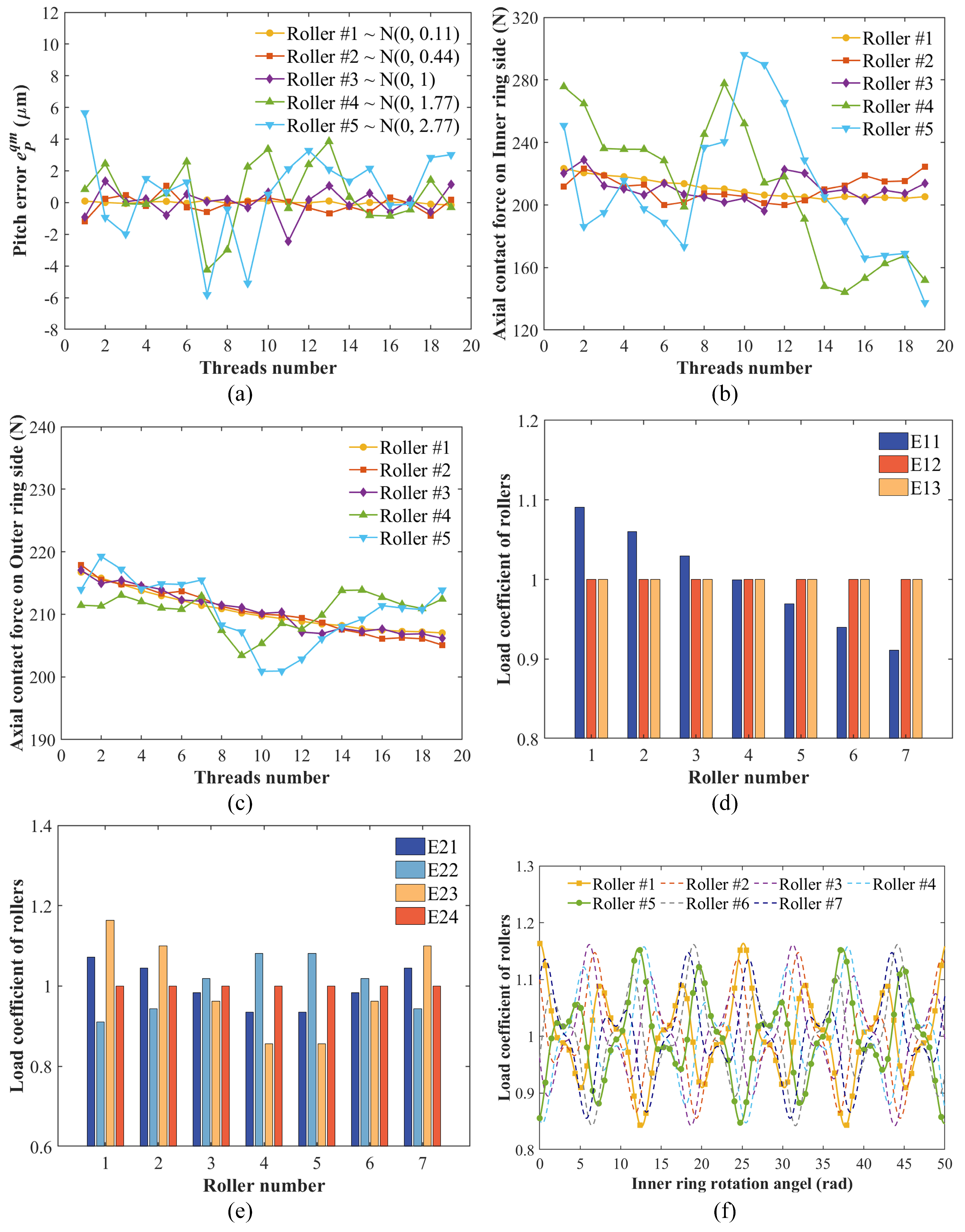
4.1. Influence of Thread Pitch Error

Five sets of normally distributed random numbers are generated using MATLAB 2021b to simulate the thread pitch errors of 5 rollers. The variance in the normal distribution is controlled to simulate different machining precisions, where smaller variances indicate higher machining precision. The generated error data are shown in Figure 12a. The calculated PTRB thread load distribution based on the thread pitch errors is shown in Figure 12b,c for an external axial load of 20 kN.
According to Figure 12b,c, the contact load on each roller’s thread fluctuates with the thread pitch error—higher thread pitch errors lead to higher load fluctuations. The load fluctuations become more pronounced as the variance of the normal distribution of thread pitch errors increases.
For Roller #1, the contact load distribution on the threads is nearly identical to that under ideal conditions with no machining errors. However, for Roller #5, significant load fluctuations are observed in the contact load distribution on the threads. On the inner ring-roller side, the contact load on the 10th thread is approximately 1.42 times that of the ideal condition. In contrast, the contact load on the 19th thread is roughly 0.67 times the ideal value.
On the outer ring-roller side, the contact load on the 19th thread is approximately 1.03 times the ideal value. The contact load on the 10th thread is roughly 0.96 times the ideal value. Furthermore, a positive thread pitch error decreases the contact load for the inner ring-roller side. In contrast, a negative thread pitch error increases contact load. The opposite is true for the outer ring-roller side. The axial clearance on the outer ring-roller side will be increased if the thread pitch error reduces the axial clearance on the inner ring-roller side and vice versa. Moreover, the inner ring-roller side is more sensitive to thread pitch errors than the outer ring-roller side. Under the same thread pitch error, the contact load fluctuations on the inner ring-roller side are more severe. This phenomenon may be related to stiffness differences of the shaft segments of the inner and outer rings.
Although thread pitch errors do not cause significant differences in LDC among rollers, they may lead to a more uneven LDC on the threads of each roller, potentially resulting in the overloading of individual threads. Consequently, the service life of PTRB is reduced. Therefore, controlling thread pitch errors can help manage thread load distribution, avoid thread overload, and improve the service performance of PTRB.

4.2. Influence of Nominal Diameter Error

The nominal diameter errors listed in Table 2 are used to investigate the effect of nominal diameter errors of the inner rings, outer rings, and rollers on the LDC among rollers. The external axial load is set to 40 kN, and the number of rollers is seven. E11 represents the nominal diameter errors for rollers #1-7 as −10 µm, −15 µm, −20 µm, −25 µm, −30 µm, −35 µm, and −40 µm, respectively. The calculated LDC among rollers is shown in Figure 12d.
The results indicate that nominal diameter errors in the inner and outer rings do not change LDC among rollers because such errors simultaneously affect the axial clearances of all engaging threads. The clearances are reduced to zero after the rigid body movement of the components. All rollers engage simultaneously, causing uniform LDC among rollers. However, varying nominal diameter errors in the rollers cause uneven LDC-rollers with smaller negative diameter deviations to bear additional load. This phenomenon occurs because smaller negative diameter deviations reduce axial clearance. Consequently, contact deformation increases compared to other rollers, leading to a higher load. Heavily loaded rollers experience accelerated wear, reducing the overall axial stiffness of PTRB. Therefore, selecting rollers with closer nominal diameters during assembly can improve the overall axial stiffness and service life of PTRB.

4.3. Influence of Axis Misalignment Error

According to design requirements, the maximum allowable deviation between the inner and outer rings’ thread axis and the reference axis is 12 µm and 15 µm, respectively, as shown in Table 1. Four possible combinations of axis misalignment errors for inner and outer rings are hypothesized, as shown in Table 3. According to Table 3, the LDC for seven rollers and an external axial load of 40 kN is shown in Figure 12e.
As shown in Figure 12e, the impact of the axial errors of the inner and outer rings on the LDC among the rollers is more significant compared to the nominal diameter error of the rollers. Given that the axial errors presented in this section are all along the X-axis of the global coordinate system, and the helix angle of the thread is 0 ° , the loads shared by each roller exhibit a symmetrical pattern with respect to the X-axis. Specifically, when the axial error combinations of the inner and outer ring are e I = [ 12   μ m , 0 , 0 ] and e O = [ 0 , 0 , 0 ] , the load on roller #1 is the greatest, approximately 1.15 times that of rollers #4 and #5 which have the smallest loads. When the axial error combinations are e I = [ 0 , 0 , 0 ] and e O = [ 15   μ m , 0 , 0 ] , the load distribution is contrary to E21, with rollers #4 and #5 become the two rollers subjected to the maximum load, which is 1.19 times that of roller #1. When the axial combination error is e I = [ 12   μ m , 0 , 0 ] and e O = [ 15   μ m , 0 , 0 ] , the load distribution among the rollers is the most unfavorable, with the load on roller #1 being 1.36 times that of rollers #4 and #5. When the axial combination error is e I = e O = [ 12   μ m , 0 , 0 ] , the loads on each roller are nearly equal. The axial deviation of the PTRB primarily alters the axial clearance, resulting in variations in the loads among the rollers. Just as described previously, the axial error of the inner ring causes the rollers along the direction of the error vector to bear a larger load, while the rollers in the opposite direction bear a smaller load. However, the outer ring behaves conversely. Therefore, for situations E21 and E22, the load on roller #1 increases and decreases, respectively. E23 deteriorates the load distribution among the rollers even further due to the opposite directions of the two error vectors. E24 is equivalent to the mutual cancellation of the axial errors, such that the load on each roller is nearly the same as that in the absence of errors.
Furthermore, when the PTRB with axial errors is in operation, the LDC among the rollers becomes complex. Figure 12f presents the calculation results of the LDC of each roller during the operation of the PTRB, where the axial error combination is E23, n r o l l e r = 7 , and F = 40   kN . As depicted in Figure 12f, the LDC of the roller exhibits a periodic pattern, with a maximum value of 1.16 and a minimum value of 0.84. Additionally, it can be observed that the LDC curves of the two rollers located at the farthest radial distance (such as roller #1 and roller #5) are approximately symmetrical, which is in accordance with the conclusion in Figure 12e. Compared with the pitch error and nominal diameter error, the influence of axial deviation on the LDC is more intricate. Hence, during the design and processing procedures, axial errors should be strictly controlled.

5. Conclusions

A computational model for the contact load distribution of PTRB that considers manufacturing errors was proposed in this paper. The sources of these errors were analyzed, and an axial clearance model was established based on the continuous tangent contact condition of two curved surfaces. A load distribution model for PTRB with multiple rollers was developed. Deformation coordination equations for each threaded contact pair were derived based on the deformation coordination condition. The model’s accuracy was verified by comparing the results with finite element simulations and the published literature. The impact of manufacturing errors on the LDC among rollers and threaded teeth was also investigated. The main conclusions are drawn as follows:
  • The proposed computational model can quickly and accurately calculate the LDC among PTRB rollers and threaded teeth while considering multiple manufacturing errors. The calculation results show a less than 10% deviation compared to the finite element simulation results.
  • Even though pitch errors may not significantly affect the LDC among rollers, they can cause uneven LDC among threaded teeth. Higher manufacturing precision can reduce pitch errors and improve LDC among threaded teeth. Additionally, the load variation on the inner ring-roller side is more pronounced than on the outer ring-roller side under the same pitch error conditions.
  • Nominal diameter errors of the inner and outer rings do not affect the LDC among rollers. However, different nominal diameter errors among rollers cause load redistribution. Rollers with smaller negative nominal diameter errors bear greater loads, making them more prone to wear. Therefore, selecting rollers with consistent nominal diameters during assembly can improve the service life of PTRB.
  • Compared to nominal diameter errors, the inner and outer ring axial errors result in a more uneven LDC among rollers. The load on the most heavily loaded roller in this study’s PTRB was approximately 1.36 times that of the least loaded roller. Additionally, PTRBs with axial errors exhibited complex load distribution in practical applications. The LDC of each roller periodically fluctuates with the inner ring’s rotation. Therefore, attention should be paid to PTRB axial errors during design and manufacturing processes.
The model presented in this paper can offer valuable insights into PTRB parameter design, parts processing, and assembly. Although the impact of machining errors on load distribution is considered in this study, a quantitative analysis of the varying degrees of influence of different machining errors on load distribution is not provided. Furthermore, due to the presence of machining errors, certain threads may experience overload during PTRB operation. Overloading leads to deformation in the thread contact area that goes beyond pure elastic behavior and enters elastoplastic deformation territory. It is not suitable to calculate the elastoplastic deformation of the contact region according to the Hertzian contact theory. Therefore, it is imperative to establish a calculation model for the load distribution of thread teeth under elastoplastic contact deformation. Additionally, during the operation of PTRB, it inevitably undergoes radial loads, and radial loads will cause changes in the load distribution among the rollers. Therefore, it is necessary to consider the radial loads to establish a load distribution calculation model. The aforementioned shortcomings will be addressed in subsequent work.

Author Contributions

Data curation, Y.H. and Z.W.; funding acquisition, Z.X.; investigation, M.L. and Y.H.; methodology, Z.X.; project administration, Z.X. and K.Z.; software, Z.X. and M.L.; supervision, Z.X.; validation, Z.X., Z.W. and K.Z.; writing—original draft, M.L.; writing—review and editing, Z.X. All authors have read and agreed to the published version of the manuscript.

Funding

This research was funded by the National Natural Science Foundation of China, grant number 52375171.

Data Availability Statement

Data are contained within the article.

Conflicts of Interest

The authors declare no conflicts of interest.

References

  1. Meng, F.N.; Wang, L.J.; Li, H.; Du, W.L.; Gong, X.Y.; Wu, C.J.; Luo, S.Q. Reliability evaluation of rolling bearings based on generative adversarial network sample enhancement and maximum entropy method. Sci. Rep. 2024, 14, 31185. [Google Scholar] [CrossRef] [PubMed]
  2. Zeng, Q.; Liu, Y.H.; Du, W.T.; Jiang, L.B.; Yu, W.N. Dynamic characteristic analysis of a gear-rotor-bearing coupling system considering bearing fit. Nonlinear Dyn. 2024, 113, 2131–2154. [Google Scholar] [CrossRef]
  3. Zheng, S.C.; Fu, Y.L.; Wang, D.Y.; Liu, Z.Y.; Pan, J.L.; Chen, J. Effect of structural parameters and load states on PTRB’s load distribution. Adv. Mech. Eng. 2023, 15, 16878132231161004. [Google Scholar] [CrossRef]
  4. Du, Z.; Zhang, X.L.; Tao, T. Study of the dynamic characteristics of ball screw with a load disturbance. Math. Probl. Eng. 2016, 2016, 8208241. [Google Scholar] [CrossRef]
  5. Zhen, N.; An, Q. Analysis of stress and fatigue life of ball screw with considering the dimension errors of balls. Int. J. Mech. Sci. 2018, 137, 68–76. [Google Scholar] [CrossRef]
  6. Wei, C.C.; Lai, R.S. Kinematical analyses and transmission efficiency of a preloaded ball screw operating at high rotational speeds. Mech. Mach. Theory 2011, 46, 880–898. [Google Scholar] [CrossRef]
  7. Zhou, H.X.; Zhou, C.G.; Ou, Y.; Chen, Z.T. Recalculation of the basic static load of ball screws. Adv. Mech. Eng. 2019, 11, 168781401986269. [Google Scholar] [CrossRef]
  8. Du, X.; Chen, B.K.; Zheng, Z.D. Investigation on mechanical behavior of planetary roller screw mechanism with the effects of external loads and machining errors. Tribol. Int. 2021, 154, 106689. [Google Scholar] [CrossRef]
  9. Hu, R.; Wei, P.T.; Liu, H.J.; Du, X.S.; Zhou, P.L.; Zhu, C.C. Investigation on load distribution among rollers of planetary roller screw mechanism considering machining errors: Analytical calculation and machine learning approach. Mech. Mach. Theory 2023, 185, 105322. [Google Scholar] [CrossRef]
  10. Liu, J. A dynamic modelling method of a rotor-roller bearing-housing system with a localized fault including the additional excitation zone. J. Sound Vib. 2020, 469, 115144. [Google Scholar] [CrossRef]
  11. Ryś, J.; Lisowski, F. The computational model of the load distribution between elements in a planetary roller screw. J. Theor. Appl. Mech. 2014, 52, 699–705. [Google Scholar]
  12. Abevi, F.; Daidie, A.; Chaussumier, M.; Sartor, M. Static load distribution and axial stiffness in a planetary roller screw mechanism. J. Mech. Des. 2016, 138, 012301. [Google Scholar] [CrossRef]
  13. Jones, M.H.; Velinsky, S.A. Stiffness of the roller screw mechanism by the direct method. Mech. Based Des. Struct. Mach. 2014, 42, 17–34. [Google Scholar] [CrossRef]
  14. Zhang, W.J.; Liu, G.; Tong, R.T.; Ma, S.J. Load distribution of planetary roller screw mechanism and its improvement approach. Proc. Inst. Mech. Eng. C J. Mec. Eng. Sci. 2016, 230, 3304–3318. [Google Scholar] [CrossRef]
  15. Zhang, W.J.; Liu, G.; Ma, S.J.; Tong, R.T. Load distribution over threads of planetary roller screw mechanism with pitch deviation. Proc. Inst. Mech. Eng. C J. Mec. Eng. Sci. 2019, 233, 4653–4666. [Google Scholar] [CrossRef]
  16. Fu, X.J.; Li, X.; Ma, S.J.; Gerada, D.; Liu, G.; Gerada, C. A multi-roller static model of the planetary roller screw mechanism considering load sharing. Tribol. Int. 2022, 173, 107648. [Google Scholar] [CrossRef]
  17. Zheng, S.C.; Fu, Y.L.; Wang, D.Y.; Pan, J.L.; Liu, Z.Y.; Chen, J. Characteristics analysis and optimization of the structural parameters of PTRB. Machines 2022, 10, 1051. [Google Scholar] [CrossRef]
  18. Ni, J.N.; Yin, J.H.; Li, D.D.; Liu, J.Q.; Xie, Z.J. Modeling of contact load distribution of planetary threaded roller bearing based on deformation coordination. Mech. Based Des. Struct. Mach. 2021, 51, 5856–5877. [Google Scholar] [CrossRef]
  19. Xie, Z.J.; Wang, Y.; Zhan, H.; Xie, W.J.; Deng, J.X.; Yu, D.; Yin, J.H. Calculation model of contact load and axial stiffness of planetary thread roller bearing based on direct stiffness method. Adv. Theory Simul. 2023, 6, 2300126. [Google Scholar] [CrossRef]
  20. Zheng, S.C.; Fu, Y.L.; Pan, J.L.; Li, L.J.; Wang, D.Y. An in-depth study on load distribution characteristics of the planetary threaded roller bearing. Math. Probl. Eng. 2020, 2020, 9593051. [Google Scholar] [CrossRef]
  21. Qiao, G.; Liu, G.; Shi, Z.H.; Wang, Y.W.; Ma, S.J.; Lim, T.C. A review of electromechanical actuators for More/All Electric aircraft systems. Proc. Inst. Mech. Eng. C J. Mec. Eng. Sci. 2018, 232, 4128–4151. [Google Scholar] [CrossRef]
  22. Sandu, S.; Biboulet, N.; Nelias, D.; Abevi, F. An efficient method for analyzing the roller screw thread geometry. Mech. Mach. Theory 2018, 126, 243–264. [Google Scholar] [CrossRef]
  23. Litvin, F.L.; Fuentes, A. Gear Geometry and Applied Theory; Cambridge University Press: Cambridge, MA, USA, 2004. [Google Scholar]
  24. Fu, X.J.; Liu, G.; Ma, S.J.; Tong, R.T.; Lim, T.C. A comprehensive contact analysis of planetary roller screw mechanism. J. Mech. Des. 2017, 139, 012302. [Google Scholar] [CrossRef]
  25. Yamamoto, S. Theory and Calculation of Screw Thread Connection; Shanghai Scientific and Technical Press: Shanghai, China, 1984. [Google Scholar]
  26. Ma, S.J.; Wu, L.P.; Liu, G.; Fu, X.J. Local contact characteristics of threaded surfaces in a planetary roller screw mechanism. Mech. Based Des. Struct. Mach. 2019, 48, 1–26. [Google Scholar] [CrossRef]
  27. Yao, Q.; Zhang, M.C.; Liu, G.; Ma, S.J. Multi-objective optimization of planetary roller screw mechanism based on improved mathematical modelling. Tribol. Int. 2021, 161, 107095. [Google Scholar] [CrossRef]
Figure 1. Coordinates of PTRB.
Machines 13 00026 g001
Figure 2. PTRB machining errors diagram: (a) thread pitch error, (b) nominal diameter error, (c) the inner ring axis misalignment error, (d) the outer ring axis misalignment error, (e) the q-th roller axis misalignment error.
Machines 13 00026 g002
Figure 3. PTRB axis misalignment errors vector diagram.
Machines 13 00026 g003
Figure 4. Axial clearances of mating thread surfaces.
Machines 13 00026 g004
Figure 5. Tooth profile of the inner ring, roller, and outer ring threads.
Machines 13 00026 g005
Figure 6. Multi-roller load distribution model of PTRB.
Machines 13 00026 g006
Figure 7. Deformation compatibility relationship of PTRB.
Machines 13 00026 g007
Figure 8. Flow chart for PTRB thread contact load calculation considering machining error.
Machines 13 00026 g008
Figure 9. Finite element model of PTRB.
Machines 13 00026 g009
Figure 10. Comparisons of load distribution between analytical and FEM: (a) inner ring side without error, (b) outer ring side without error, (c) inner ring side with roller nominal diameter error, (d) outer ring side with roller nominal diameter error.
Machines 13 00026 g010
Figure 11. Comparison of the LDC between this paper and the reference [20].
Machines 13 00026 g011
Figure 12. Load distribution of PTRB considering machining errors: (a) thread pitch error of each roller, (b) load distribution on the inner ring-roller side considering roller thread pitch error, (c) load distribution on the outer ring-roller side considering roller thread pitch error, (d) LDC among rollers considering nominal diameter error, (e) LDC among rollers considering axis misalignment error, (f) LDC among rollers considering axis misalignment error when the PTRB is in operation.
Machines 13 00026 g012
Table 1. Structural parameters of PTRB.
ParametersSymbolsInner RingRollerOuter Ring
Nominal diameter d i /mm18931.5252
Major diameter d i a /mm190.2532.75253.75
Minor diameter d i f /mm187.2529.75250.75
Pitch P /mm555
Flank angel β i /mm454545
Outer ring external diameter D O /mm292
Inner ring internal diameter D I /mm131
Roller profile radius r p q /mm22.274
Number of rollers n r o l l e r 11
Number of threads n T 191919
Table 2. Nominal diameter error of PTRB.
No.Nominal Diameter Error (μm)
E11 e r q = [−10, −15, −20, −25, −30, −40]
E12 e r I = −20
E13 e r O = 20
Table 3. Axis misalignment error of PTRB.
No.Eccentricity Error of Inner RingEccentricity Error of Outer Ring
E21 e I = [12 μm, 0, 0] e O = [0, 0, 0]
E22 e I = [0, 0, 0] e O = [15 μm, 0, 0]
E23 e I = [12 μm, 0, 0] e O = [−15 μm, 0, 0]
E24 e I = [12 μm, 0, 0] e O = [12 μm, 0, 0]
Disclaimer/Publisher’s Note: The statements, opinions and data contained in all publications are solely those of the individual author(s) and contributor(s) and not of MDPI and/or the editor(s). MDPI and/or the editor(s) disclaim responsibility for any injury to people or property resulting from any ideas, methods, instructions or products referred to in the content.

