Abstract
During the axial modification in helical gear form grinding, the contact line between the grinding wheel and the gear constantly changes, and the additional radial motion can cause a “tooth surface twist” phenomenon. An optimization method for tooth surface twist error was proposed to address this. Based on the gear meshing principles, a mathematical model for axial modification in form grinding was established to solve for the instantaneous contact lines at various positions on the actual modified tooth surface. By analyzing the influence of the grinding wheel installation angle on the axial modification contact line, an optimization model was constructed to reduce the twist of the transverse profile, reduce the twist of the flank profile, reduce the helix deviation, and improve the form grinding efficiency. The practical implications of this research are significant, as the Particle Swarm Optimization (PSO) algorithm was employed to optimize the form grinding parameters, leading to a method that effectively reduced tooth surface twist error and improved the form grinding accuracy of the modified tooth surface.
1. Introduction
Gear modification is an effective method to improve gear transmission performance. It is possible to reduce meshing impact, improve load distribution, and lower system vibration response through modification. It is difficult to precisely achieve the theoretical tooth profile for complex tooth profiles that meet the preset modification amount due to the machining principle and machine movement errors during the machining process. Therefore, it is crucial to study the impact weights of the various parameters on the final tooth surface during machining, optimize the tooth surface, and achieve smooth and low-noise gear transmission under high-speed and heavy-load conditions [1,2].
In recent years, gear design and manufacturing research have advanced significantly, with many scholars conducting in-depth studies on tooth profile design, tooth surface modification, and gear meshing mechanisms. Litvin et al. [3,4] established a mathematical model for form grinding. They calculated the instantaneous contact lines between the grinding wheel and the gear, providing a theoretical foundation for the grinding process. Dudley [5] developed corresponding mathematical models for the gear meshing principles, spatial coordinate transformations, and tooth surface contact analysis, laying a solid foundation for developing the gear modification theory. Gregory et al. [6] noted that gear tooth profile modification can improve the tooth contact conditions and reduce the dynamic loads. The slight geometric modification of the involute tooth profile can significantly impact the dynamic and static characteristics of gear meshing. Ren et al. [7] established an accurate mathematical model for gear form grinding force using mathematical methods. Their research findings contribute to the rational selection of grinding process parameters, wheel dressing control, and gear grinding quality assurance. Liu et al. [8] analyzed and experimentally studied the effects of wheel dressing surfaces on workpiece surface texture and grinding forces. They developed an analysis model for the dressing point profile to describe the kinematics of the wheel surface dressing process. Using parameters such as texture width, texture length, texture angle, and texture function parameters, they described patterned surface textures and revealed the influence of wheel dressing morphology on the surface texture of the machined workpiece. Gorla et al. [9] established a gear tooth surface model based on form grinding and analyzed the impact of the grinding wheel installation center distance and installation angle on tooth surface accuracy. Shih et al. [10] studied the calculation method for the grinding wheel’s axial section profile and analyzed the effects of the workpiece and wheel installation angle, center distance, and axial displacement on the grinding wheel section profile. These studies primarily address critical issues in the gear form grinding process, including the calculation of instantaneous contact lines between the grinding wheel and the gear, the construction of mathematical models for gear meshing principles, the improvement of gear contact conditions and dynamic loads through tooth profile modification, the accurate modeling of grinding forces, the analysis of the effects of wheel dressing on workpiece surface texture and grinding forces, and the impact of wheel installation center distance and angle on tooth surface accuracy. These studies provide a theoretical foundation, process optimization methods, and precision control techniques for gear grinding, effectively enhancing the quality and efficiency of the process.
In analyzing and compensating the tooth profile and axial modification errors, Yoshino et al. [11] numerically studied the impact of positioning errors on the profile error of ground helical gears and proposed two practical methods for compensating gear profile errors using positioning errors. Kobayashi [12] determined that by providing the tangent coordinates and slopes of points on the tooth profile, the optimal grinding wheel installation angle for achieving the shortest contact line extension length without interference can be found. Nishida et al. [13] calculated the tooth profile of a gear based on the tangent coordinates and slopes of points on the sand profile and determined the optimal installation angle that minimizes machining errors according to the specifications of the sand profile. Korta et al. [14] introduced the application of response surface methodology (RSM) in optimizing microscopic corrections to gear profiles. They proposed a tooth surface modification optimization method based on RSM and illustrated it by finding the optimal micro-geometric modifications for a spur cylindrical gear. Yu et al. [15] proposed a new method for MACLA envelope grinding using ultra-thin diamond grinding wheels with higher-order curved section profiles to compensate for dressing errors directly. They established a mathematical model for the grinding wheel with a higher-order curved section profile and a grinding wheel path model. Givi et al. [16] proposed a general volumetric error formulation that effectively implemented the ISO230-1:2012 [17] definition and an offline compensation scheme, which was partly tested to improve part accuracy on a five-axis CNC machine. Xia et al. [18] studied the geometric errors present during gear grinding and proposed an error compensation method to improve the accuracy of gear grinding processes. Yoshino et al. [19] studied the impact of positioning errors on the profile of ground helical gears and proposed two methods for compensating gear profile errors using positioning errors, effectively reducing the involute helical gear profile error. These articles primarily address the issue of tooth surface errors in the gear grinding process caused by positioning errors, grinding wheel installation angle, and modification methods. These studies propose practical solutions for compensating tooth profile errors through numerical analysis and optimization approaches. These include optimizing the grinding wheel installation angle, applying response surface methodology to optimize micro-geometry corrections of the tooth surface, using ultra-thin diamond grinding wheels for grinding error compensation, and proposing geometric error compensation methods to improve grinding accuracy. These studies offer new solutions for reducing gear machining errors and enhancing the precision of gear grinding.
Particle Swarm Optimization, initially developed by Kennedy and Eberhart [20], is a meta-heuristic global optimization method that belongs to the family of algorithms based on the concept of swarm intelligence. Li et al. [21] proposed a PSO-based optimization method for the contact line between a profile grinding wheel and gear; the gear form grinding test results showed that the proposed method can improve grinding accuracy. Li et al. [22] used Particle Swarm Optimization (PSO) to optimize the initial value of the network to make the training more stable; the proposed method was validated through the data collected from the gear pitting test experiment; the validation results showed that the fault diagnosis accuracy could reach 100%, which proves that the proposed method is reasonable.
There is a growing need for advanced computational models capable of more accurately predicting the impact of complex modifications on gear performance. Minimizing tooth surface twist errors and deviations remains a significant challenge in achieving high precision in the form grinding process. Further refinement of these models is essential to enhance accuracy and computational efficiency, particularly for practical applications. Axial modification can improve the uneven load distribution along the tooth direction, but it simultaneously leads to uneven material removal along the tooth direction, resulting in tooth surface twists [23]. Tooth surface twists can cause an increase in tooth flank clearance and a reduction in transmission accuracy, leading to poorer meshing performance and increased meshing noise. Since the contact line of a helical gear is not parallel to the helix, helix deviations affect the load distribution uniformity and the smoothness of transmission, thereby impacting the gear’s transmission precision and service life [24]. This paper proposes an optimization method for form grinding to improve form grinding performance, reduce tooth surface twist error, and reduce helix deviation. The evaluation functions used include the twist of the transverse profile, the twist of the flank profile, helix deviation, and grinding stroke. The Particle Swarm Optimization (PSO) algorithm was employed to optimize the multi-objective functions, determining the optimal contact line between the helical gear and the form grinding wheel. Finally, the accuracy of the model was verified through simulation analysis.
2. Establishment of Form Grinding Coordinate System and Solution of Grinding Wheel Profile
2.1. Establishment of Spatial Meshing Coordinate System for Form Grinding
When machining a helical surface workpiece with a disc grinding wheel, their relative position is illustrated in Figure 1. A coordinate system is established on the gear, which is rigidly connected to the gear; a coordinate system is established on the grinding wheel, which is rigidly connected to the grinding wheel. The axes and coincide but are directed oppositely; the axis coincides with the gear axis, and the axis aligns with the tool axis. The shortest distance between the axes (center distance) is denoted as , and the angle between the grinding wheel’s axis and the workpiece’s axis is denoted as . The coordinate system axes are defined to fit the right-hand rule. During the grinding process, the gear performs rotary motion while the grinding wheel moves along the gear axis and undergoes additional radial motion. Therefore, and can represent the relative position of and [25]. The transformation relationship between these two coordinate systems is as follows:
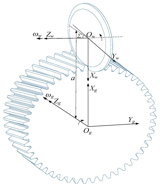
Figure 1.
Coordinate System for Helical Gear Form Grinding.
2.2. Calculation of Grinding Wheel Section Profile
In forming grinding helical gears, the spatial contact line between the grinding wheel and the gear is determined by analyzing the wheel installation parameters and the spatial helical tooth surface shape of the helical gear described in Equation (3), satisfying the contact line equation [25].
In the Equation, denotes the radius vector of a point on the involute curve; represents the pressure angle at that point; denotes the spiral parameter of the gear; represents the angle turned by the gear; is the radius of the base circle; is the angle between the starting point of the involute and the axis; is the unfolding angle of the involute; and is the normal vector at a point on the helical surface of the helical gear.
The contact line obtained from Equation (4) is a spatial curve on the grinding wheel’s rotational surface. By rotating this contact line around the wheel’s axis , the rotational surface of the grinding wheel can be derived. The contact line is transformed from the gear coordinate system to the grinding wheel coordinate system using the coordinate transformation defined in Equation (1) [25]. Thus, the axial cross-section of the grinding wheel’s rotational surface can be determined as follows:
In the Equation, denotes the radius of the grinding wheel; represents the width of the grinding wheel.
The axial cross-section of the grinding wheel is derived from Equation (5) as a curve within the plane . In the grinding wheel coordinate system , the wheel’s cross-section can be represented as follows:
3. Construction of Digital Tooth Surface for Axial Modification
3.1. Analysis of Axial Modification
As shown in Figure 2, taking an axial drum-shaped modification with additional radial motion as an example, a drum shape curve is established at the tooth tip of the gear. Let represent the tooth width, denote the maximum modified quantity, and the trajectory of the additional radial motion follows a parabolic path. The modified quantity at is zero, while represents the drum radius, with the drum-shaped modification amount at each point denoted as .
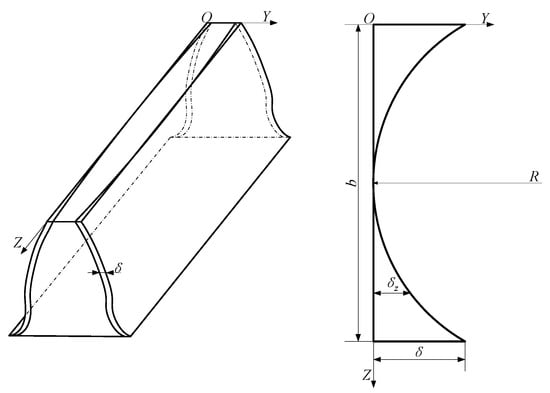
Figure 2.
Axial Drum-Shaped Modification.
From the relationship shown in Figure 2, the radius of the drum can be determined as follows:
Consequently, the drum-shaped modification amount at each point is given by the following:
In the equation, denotes the spiral parameter of the gear; represents the angle turned by the gear.
The change in center distance can be expressed as follows:
In the equation, denotes the normal pressure angle; represents the base helix angle.
Consequently, it can be determined that when the gear rotates by a unit angle, the radial velocity of the grinding wheel along the gear is given by the following:
In the equation, represents the time the gear rotates at a unit angle at an angular velocity of .
3.2. Actual Contact Line for Axial Modification
The grinding wheel’s planar curve, derived from Equation (6), is rotated around the axis, thereby forming the grinding wheel’s rotational surface.
In the equation, represents the angle at which the grinding wheel rotates.
The following Equation can determine the normal vector of the grinding wheel’s rotative surface:
The actual modified tooth surface is formed by the combined motion of the grinding wheel’s additional radial motion trajectory and its movement along the axis. The resulting contact line is the actual modified tooth surface contact line. Let the gear’s angular velocity be denoted as , and the radial vectors in the coordinate systems and are represented by and , respectively; .
Consequently, the angular velocity of the gear in the grinding wheel coordinate system is obtained as follows:
The relative velocity between the grinding wheel and the gear in the grinding wheel coordinate system is as follows:
In the equation, represents the velocity of the gear in the grinding wheel coordinate system ; and represents the velocity of the grinding wheel in the coordinate system .
By substituting the above calculation results into the engagement conditions equation between the grinding wheel and the gear, the following equation is obtained:
According to the solution process of the engagement conditions equation between the grinding wheel and the gear, Equation (18) is a transcendental equation involving , , and , making it difficult to obtain an analytical solution directly. The Newton iteration method can solve it by traversing the parameters and within the domain. represents the angle rotated during the engagement process, and is a discrete value within the definition domain of the grinding wheel radius. By substituting into Equation (18) for iterative computation, the calculated values are then substituted into the following equation to obtain the coordinates of the points on the actual contact line [25].
3.3. Construction of Modified Tooth Surface Based on NURBS
Non-uniform rational B-spline (NURBS) is a mathematical model that uses B-splines as basis functions, with non-uniform knot spacing and weighted control points, to represent complex geometric shapes. NURBS can precisely represent complex geometries and offers significant advantages over other methods. It provides a unified mathematical representation for standard analytical shapes and the precise design of free-form curves and surfaces.
The rational expression of a NURBS surface with degree in the direction and degree in the direction, i.e., a times NURBS surface, is shown in Equation (20) [26].
where —Control points forming a bidirectional control mesh arranged in a topological rectangular grid;
—Control point u-direction numbering and u-direction B-spline basis function numbering;
—Control point v-direction numbering and v-direction B-spline basis function numbering;
—The weight factor corresponding to the control point;
—The u-directed p-times B-spline basis functions, determined by the u-directed node vectors according to the Boolean recurrence formula;
—The v-directed p-times B-spline basis functions, determined by the v-directed node vectors according to the Boolean recurrence formula.
This paper employs a method based on the NURBS interpolated surfaces for constructing the tooth surface. The reverse calculation process for the NURBS interpolated surface involves creating a NURBS surface that accurately passes through the specified data points . Eleven equidistant end sections are selected along the tooth width, with 11 points discretized on the gear end section profile. This results in the actual tooth surface comprising 11 × 11 tooth surface points, denoted as data points .
As shown in Figure 3a, the data point network of the tooth surface is illustrated, with black dots indicating the positions of the data points. The bidirectional cubic NURBS interpolation surface reverse calculation method is used to construct the node vectors in the and directions.

Figure 3.
Tooth Surface Model: (a)Tooth Surface Data Point Network, (b)Tooth Surface Control Point Network, and (c)Tooth surface continuum model.
Curve interpolation is performed on the data points in the u-direction along the node vector , resulting in NURBS curves and their corresponding control points. Similarly, curve interpolation is performed on the data points in the v-direction along the node vector , yielding NURBS curves and their control points. This process produces the corresponding control mesh, as shown in Figure 3b, where the weights of all control points are set to 1. Finally, the tooth surface model, as shown in Figure 3c, is obtained using the forward calculation method of NURBS surfaces.
3.4. Construction of Theoretical Modified Tooth Surface
Since the axial modification curve is superimposed on the graduated circle helix, it can be considered a change in the end section tooth profile along the axial direction. The actual modification outline shape of the tooth profile is formed by rotating the pre-modification tooth profile by an angle around the axis, as shown in Figure 4. The relationship between the rotation angle and the drum-shaped modification amount at various points can be expressed as follows:
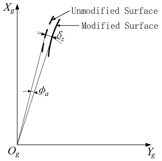
Figure 4.
Schematic Diagram of Axial Modification Curve.
In the equation, represents the radius of the graduated circle.
Consequently, the theoretical equation for the axial modification tooth surface can be derived as follows:
In the equation, represents the angle through which the gear has rotated.
4. Error Analysis of Modified Tooth Surface
4.1. Instantaneous Contact Line for Axial Modification
During form grinding, the contact line is a spatial curve, and its spatial configuration is primarily influenced by process parameters, including the grinding wheel cross-section shape, grinding wheel installation angle, grinding wheel radius, and center distance. In the actual machining process, the form grinding wheel tends to wear down, causing the grinding wheel radius to decrease gradually and making it difficult to maintain a consistent radius during wheel dressing. The center distance of the grinding wheel is not fixed due to the influence of radial displacement. As mentioned earlier, this distance is a function. Therefore, this paper proposes optimizing the spatial contact line by adjusting the grinding wheel installation angle to compensate for tooth surface errors. Under the condition that no curvature interference occurs between the wheel section form and the tooth profile, the installation angle is no longer fixed at but somewhat varies within the boundary range of .
For a helical gear with a tooth count of , a face module of , a helix angle of , and an initial center distance of , the projection pattern of the contact line on the plane is analyzed as the grinding wheel installation angle varies.
As shown in Figure 5, when the grinding wheel installation angle changes from 78° to 79.5°, the axial length of the contact line on the tooth surface along the axis increases. Conversely, when the grinding wheel installation angle changes from 78° to 76.5°, the axial length of the contact line along the axis initially shortens and then increases, following a process from small to large.
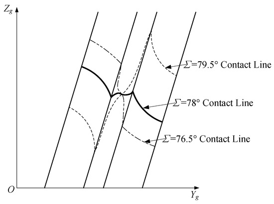
Figure 5.
Influence of Grinding Wheel Installation Angle on the Contact Line.
During the form grinding process, the grinding stroke of the wheel in the tooth slot is not fixed based on the tooth width ; rather, the variation in the grinding stroke depends on the axial length of the contact line on both sides of the grinding wheel and gear along the gear’s axis. As shown in Figure 6, the translational speed of the grinding wheel along the direction is constant, so reducing the grinding stroke shortens the grinding time. Therefore, optimizing the grinding wheel installation angle to reduce the axial length can improve grinding efficiency.
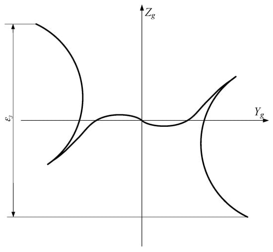
Figure 6.
Projection of the Contact Line on the Yg0gZg Plane.
4.2. Axial Error Analysis
In the grinding process of axial modification for the helical gears, the radial additional motion needs to be superimposed, which leads to an uneven removal of the tooth surface during machining, resulting in principle errors in the processed tooth surface. As shown in Figure 7, the contact line between the grinding wheel and the tooth surface is a spatial curve, causing different amounts of grinding at the tooth tip and tooth root at the same height. This results in one end being over-modified and another under-modified, leading to varying modified quantities on the same tooth surface profile and causing a “tooth surface twist” phenomenon. Figure 7 illustrates that multiple contact lines correspond to the end section tooth profile along the axial direction during axial modification grinding. These contact lines have different shapes during spatial meshing, and the modified quantities also vary, which leads to errors in the machined end section tooth profile.
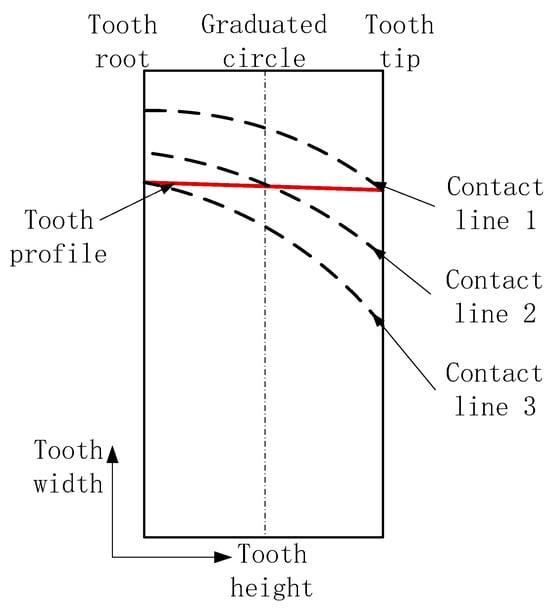
Figure 7.
Principle Error of the Machined Tooth Surface.
Based on Equation (19), the coordinates of points on the actual contact line are determined. A bicubic NURBS surface fitting is then performed as described in Section 3.3, using the control point weight factors in the and directions as design variables to construct the actual axial modification tooth surface model of the involute helical gear. The normal vectors and equations at each point on the actual modified tooth surface are then calculated. The normal equation intersects the theoretical involute tooth surface, constructed in Section 3.4, at point . The distance between point and point on the actual modified tooth surface is the normal offset distance at that point, representing the error on the actual modified tooth surface.
According to ISO21771:2007 [27], a twist is defined as an effect on a flank described as a rotation of the transverse profile along a helix. The phenomenon of tooth surface twist can be described through the twist of the transverse profile () and the twist of the flank profile (). In Figure 8, when form grinding is applied to the gear, the tooth surface exhibits a “tooth surface twist.” Using a grinding wheel installation angle of as an example, the simulation error distribution shows that the tooth profile errors are most significant at engaging-in and engaging-out. During engaging-in, the errors at the tooth tip, involute, and tooth root are −24.24 μm, 14.91 μm, and −12.98 μm, respectively. During engaging-out, the errors are −29.11 μm at the tooth tip, 13.84 μm at the involute, and −11.41 μm at the tooth root. The entire tooth surface is twisted, with a maximum twist of the transverse profile and a maximum twist of the flank profile .
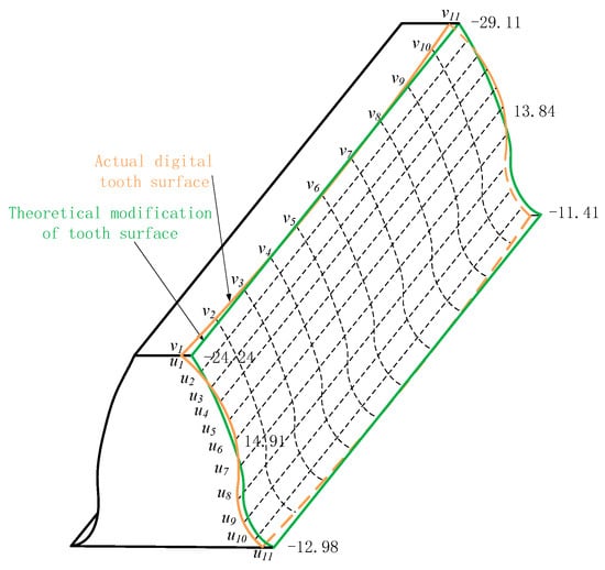
Figure 8.
Tooth Surface Error Caused by the Contact Line.
4.3. Helix Error Analysis
A graduated circle cylindrical surface is constructed along the axis of the gear, and this surface intersects with the actual axial modification tooth surface model. The intersection points between the tooth surfaces on both sides of the tooth slot and the graduated circle form the axial modification tooth surface helix. As shown in Figure 9, a standard helix is constructed along the tooth width direction at the intersection point of the axis and the graduated circle. On the same graduated circle, the distance from the intersection of the helix and the graduated circle to the intersection of the left tooth surface and the graduated circle is denoted as , and the distance from the intersection of the helix and the graduated circle to the intersection of the suitable tooth surface and the graduated circle is denoted as . gives the helix deviation at that point.
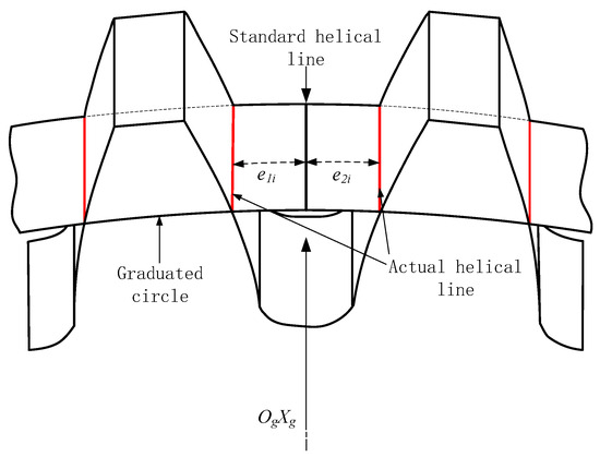
Figure 9.
Helix Error Analysis.
According to ISO1328-1:2013 [28], helix deviation is defined as the amount by which the actual helix deviates from the design helix. The total helix deviation is defined as the absolute difference between the maximum and minimum deviation distances between the design helix and the measured helix and can be expressed as follows:
5. Establishment and Solution of Multi-Objective Optimization Model
5.1. Multi-Objective Optimization Model
When performing double-sided grinding, the multi-objective optimization problem mentioned earlier is transformed into a single-objective optimization problem using an evaluation function. The Weighted Sum Method is employed by assigning different weight values to multiple objective functions and summing them to form a single objective function, thereby converting the multi-objective problem into a single-objective problem for solution. Considering the influence of each objective function, a weight is introduced to determine its impact on the objective function. Therefore, the evaluation function for the grinding wheel installation angle in form grinding can be expressed as follows:
Here, , , , are the weights for each objective, with , , , and .
In the actual simulation calculations, the theoretical modified tooth surface is known, along with the axial modification tooth surface model, which is constructed based on a series of corresponding discrete points along the spatial contact line. By calculating the average offset distance of each point on the actual modified tooth surface, the maximum twist of the transverse profile and the maximum twist of the flank profile can be determined.
According to the simulation verification, the relationship between the installation angle and , is shown in Figure 10.
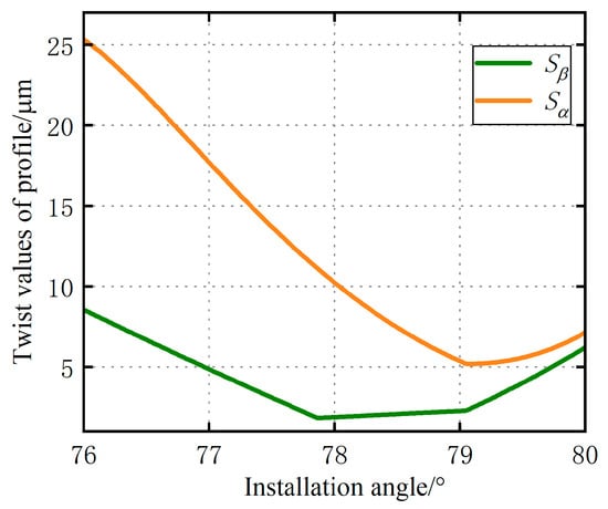
Figure 10.
Relationship Between Installation Angle and Evaluation Functions and .
A graduated circle cylindrical surface is constructed along the axis of the gear, intersecting with the actual axial modification tooth surface model. The intersections of the tooth surfaces on both sides of the tooth slot with the cylindrical surface form the actual axial modification tooth surface helices. The total helix deviation is defined as the absolute difference between the maximum and minimum deviation distances between the design helix and the measured helix.
According to the simulation verification, the helix deviation at each point, denoted as , can be determined based on the graduated circles generated along the tooth width direction. Through simulation verification, the relationship between installation angle and is shown in Figure 11.
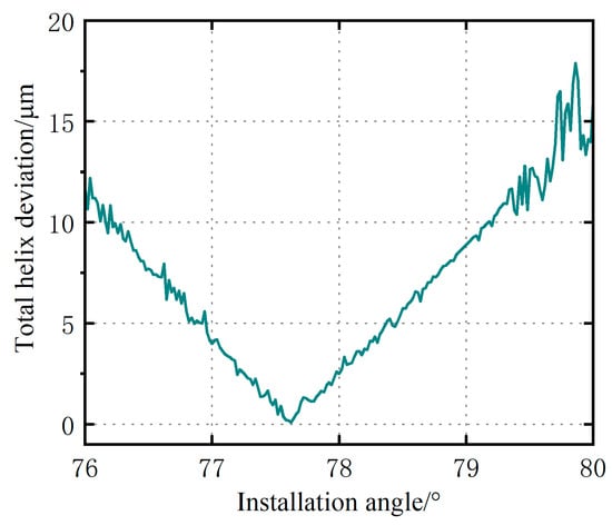
Figure 11.
Relationship Between Installation Angle and Evaluation Function .
When optimizing the gear parameters for form grinding, it is essential to improve machining efficiency while ensuring the quality of the process. During helical gear grinding, one side of the contact line along the tooth width direction first contacts the gear, and the other side of the contact line is the last to disengage from the gear at the end of the process. The actual stroke of the grinding wheel in the tooth slot is the sum of the tooth width, and the distances between the contact lines on both sides are denoted as . Reducing the grinding stroke shortens the grinding time and improves efficiency. According to the simulation verification, the relationship between the installation angle and is shown in Figure 12.
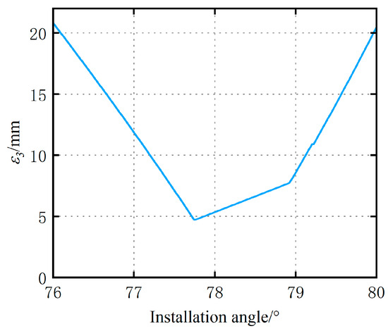
Figure 12.
Relationship Between Installation Angle and Evaluation Function .
The four optimization objectives are reducing the twist of the transverse profile, reducing the twist of the flank profile, reducing the helix deviation, and improving the form grinding efficiency. In engineering practice, the judgment matrix method can determine the weight coefficients of different objective functions. Each element in the judgment matrix represents the importance ratio of the i-th objective function to the j-th objective function. Assuming there are objective functions, the weight coefficients between all the objective functions can be given as follows:
Construct an optimized judgment matrix that includes four objective functions.
The weight coefficient can be expressed as follows:
The final evaluation function can be expressed as follows:
5.2. Optimization Algorithm
The Particle Swarm Optimization (PSO) algorithm measures the quality of individuals using an evaluation function. Based on this function, it obtains fitness values to perform random searches within the population. The PSO algorithm modifies individuals by adjusting their random velocities, making the computational process straightforward and free from genetic operations such as crossover and mutation. In terms of search performance, it is slightly superior to the Genetic Algorithm (GA).
The PSO algorithm begins by initializing the particle swarm, randomly assigning initial positions and velocities to each particle. These positions and velocities should be within the defined problem space while also initializing each particle’s individual and global best positions. Next, the algorithm evaluates the current position of each particle based on the calculated objective function, updating both the individual and global best positions. Finally, the algorithm assesses the fitness value of each particle’s function, updates each particle’s historically best position, and iteratively approaches the optimal solution. The PSO algorithm is conceptually simple, easy to program, and requires minimal parameter tuning. The algorithm exhibits strong global search capabilities by sharing information among all particles in the swarm. It is suitable for continuous, discrete, and multi-objective optimization problems and has demonstrated exemplary performance across various application domains.
Assume there are particles in an n-dimensional space, with each particle’s position defined as . The objective function is used as the fitness value . In each iteration, the objective function value of each particle is calculated, and two “extreme values” are compared, with the best solution saved as the current extreme value. The current velocity of each particle is denoted as , and the best position a particle has achieved is represented as . Each particle updates its velocity and position using the following equations:
where is the velocity of particle in the t-th generation; is the particle’s inertia weight; and are acceleration coefficients, representing the cognitive learning factor and the social learning factor, respectively; and are two mutually independent random numbers between 0 and 1; is the best position the particle has achieved; and is the global best position achieved by the entire particle swarm.
5.3. Optimization Results
A Particle Swarm Optimization (PSO) algorithm was implemented in Mathematica, with the population size set to 50 and the maximum number of iterations set to 200. The learning factors were , the inertia weight , and the independent random numbers . The weight coefficients calculated in Section 5.1 were , , , and for optimization.
In this paper, a right-hand involute helical gear was selected for tooth surface construction. The parameters for the simulated axial modification gear are shown in Table 1.

Table 1.
Gear parameters for axial modification.
Figure 13 shows the variation in fitness value over 200 iterations of the PSO algorithm. The evaluation function curve of the form grinding optimization model is smooth and gradually decreases, stabilizing after 15 iterations, at which point the evaluation function reaches its minimum value. During the simulation, the PSO model determined the optimal installation angle of the form grinding wheel to be 77.7551°. By comparing this angle with the original installation angle of 77°, it can be observed that the change in the installation angle of the form grinding wheel significantly impacts the contact line, assuming all other conditions remain unchanged.
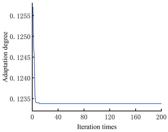
Figure 13.
PSO Results.
During engaging-in, the error is 0.43 μm at the tooth tip, 13.57 μm at the involute, and 8.26 μm at the tooth root. During engaging-out, the error is 1.79 μm at the tooth tip, 13.75 μm at the involute, and 10.07 μm at the tooth root. The maximum twist of the transverse profile was reduced by 53.22%, and the maximum twist of the flank profile was reduced by 54.41%. The total helix deviation decreased from 4.00 μm to 1.09 μm, with a reduction of 72.75%. The distance between contact lines decreased from 11.88 mm to 5.14 mm, improving machining efficiency by 3.18%.
6. Conclusions
A gear axial grinding optimization method was proposed based on the Particle Swarm Optimization (PSO) algorithm. A mathematical model for axial modification in form grinding was established based on gear meshing principles to solve the instantaneous contact lines at multiple positions on the actual modified tooth surface. By analyzing the influence of the grinding wheel installation angle on the contact line during axial modification, the following four objective functions were used: twist of the transverse profile, twist of the flank profile, the helix deviation, and the grinding stroke to optimize the final evaluation model. The grinding wheel installation angle was used as the input, and the evaluation model was the output for solving the optimization problem.
This study systematically investigated the relative motion between the form grinding wheel and the helical gear, calculated the mathematical model of the actual modified tooth surface, and revealed the tooth surface twist error. In double-sided grinding, the evaluation model was used to convert the multi-objective optimization problem into a single-objective optimization problem.
The results show that after optimization, the maximum twist of the transverse profile was reduced by 53.22%, and the maximum twist of the flank profile was reduced by 54.41%. The total helix deviation decreased from 4.00 μm to 1.09 μm, with a reduction of 72.75%. The distance between the contact lines decreased from 11.88 mm to 5.14 mm, resulting in a 3.18% improvement in machining efficiency. In the future, the optimization method for reducing the principle errors of the axial modification tooth surface, based on the Particle Swarm Optimization (PSO) algorithm proposed in this paper, will be integrated into the CNC system of the form grinding machine developed by our research group and further refined through actual machining experiments.
Author Contributions
Conceptualization, methodology, software, validation, formal analysis, writing—original draft preparation, writing—review and editing, visualization, supervision, B.Z. and Y.Z.; investigation, resources, data curation, L.Z., Q.L. and X.W. All authors have read and agreed to the published version of the manuscript.
Funding
This research was funded by the National Natural Science Foundation of China (52227809).
Data Availability Statement
Date are contained within the article.
Acknowledgments
Thank you for the reviewers’ comments and the editors’ work.
Conflicts of Interest
The authors declare no conflicts of interest.
References
- Kahraman, A.; Blankenship, G.W. Effect of involute tip relief on dynamic response of spur gear pairs. J. Mech. Des. 1990, 121, 313–315. [Google Scholar] [CrossRef]
- Faggioni, M.; Samani, F.S.; Bertacchi, G.; Pellicano, F. Dynamic optimization of spur gears. Mech. Mach. Theory 2010, 46, 544–557. [Google Scholar] [CrossRef]
- Litvin, F.L.; Fuentes, A. Gear Geometry and Applied Theory; Cambridge University Press: Cambridge, UK, 2004. [Google Scholar]
- Litvin, F.L.; Chen, N.X.; Lu, J.; Handschuh, R.F. Computerized design and generation of low-noise helical gears with modified surface topology. J. Mech. Des. 1995, 117, 254–261. [Google Scholar] [CrossRef][Green Version]
- Dudley, D.F. Dudley’s Handbook of Practical Gear Design and Manufacture, 2nd ed.; McGraw-Hill: New York, NY, USA, 1991. [Google Scholar]
- Gregory, R.W.; Harris, S.L.; Munro, R.G.; Graduate. Dynamic behaviour of spur gears. Proc.-Inst. Mech. Eng. 1963, 178, 207–218. [Google Scholar] [CrossRef]
- Ren, X.Z.; Ding, J.P.; Su, J.X.; Du, X.Y. Research on mathematical model of grinding force in gear form grinding. Key Eng. Mater. 2011, 464, 401–404. [Google Scholar] [CrossRef]
- Liu, Y.; Gong, S.; Li, J.; Cao, J. Effects of dressed wheel topography on patterned surface textures and grinding force. Int. J. Adv. Manuf. Technol. 2017, 93, 1751–1760. [Google Scholar] [CrossRef]
- Gorla, C.; Rosa, F. Form grinding of helical gears: Effects of disk shaped tools plunging. In Proceedings of the 9th International Power Transmission and Gearing Conference, Chicago, IL, USA, 2–6 September 2003; Volume 4. Parts A and B. [Google Scholar]
- Shih, Y.-P.; Chen, S.-D. A flank correction methodology for a five-axis CNC gear profile grinding machine. Mech. Mach. Theory 2012, 47, 31–45. [Google Scholar] [CrossRef]
- Yoshino, H.; Ikeno, K. Error compensation for form grinding of gears. Trans. Jpn. Soc. Mech. Eng. 1991, 57 Pt C, 3652–3655. [Google Scholar] [CrossRef]
- Kobayashi, Y.; Nishida, N.; Ougiya, Y.; Nagata, H. Tooth trace modification processing of helix gear by form grinding method. Trans. Jpn. Soc. Mech. Eng. 1995, 61 Pt C, 4088–4093. [Google Scholar] [CrossRef]
- Nishida, N.; Kobayashi, Y.; Ougiya, Y.; Nagata, H. Tooth flank modification processing of helical gears by form grinding method. Trans. Jpn. Soc. Mech. Eng. 1999, 65 Pt C, 4458–4463. [Google Scholar] [CrossRef]
- Korta, J.A.; Mundo, D. Multi-objective micro-geometry optimization of gear tooth supported by response surface methodology. Mech. Mach. Theory 2017, 109, 278–295. [Google Scholar] [CrossRef]
- Yu, S.; Yao, P.; Xu, J.; Wang, W.; Li, Y.; Chu, D.; Qu, S.; Huang, C. Profile error compensation in ultra-precision grinding of aspherical-cylindrical lens array based on the real-time profile of wheel and normal residual error. J. Mater. Process. Technol. 2023, 312, 117849. [Google Scholar] [CrossRef]
- Givi, M.; Mayer, J.R.R. Volumetric error formulation and mismatch test for five-axis CNC machine compensation using differential kinematics and ephemeral G-code. Int. J. Adv. Manuf. Technol. 2015, 77, 1645–1653. [Google Scholar] [CrossRef]
- ISO 230-1; Test Code for Machine Tools—Part 1: Geometric Accuracy of Machines Operating under No-Load or Quasi-Static Conditions. ISO: Geneva, Switzerland, 2012.
- Xia, C.; Wang, S.; Ma, C.; Wang, S.; Xiao, Y. Crucial geometric error compensation towards gear grinding accuracy enhancement based on simplified actual inverse kinematic model. Int. J. Mech. Sci. 2020, 169, 105319. [Google Scholar] [CrossRef]
- Yoshino, H.; Ohshima, F. Error compensation of work setting in form grinding of gears. Proc. Mach. Des. Tribol. Div. Meet. JSME 2003, 3, 55–56. [Google Scholar]
- Eberhart, R.; Kennedy, J. A new optimizer using particle swarm theory. In Proceedings of the Sixth International Symposium on Micro Machine and Human Science, Nagoya, Japan, 4–6 October 1995. [Google Scholar]
- Li, Y.; Li, G.; Wang, Z.; Zhu, W. A form-grinding wheel optimization method for helical gears based on a PSO-SVM model. Precis. Eng. 2024, 88, 664–673. [Google Scholar] [CrossRef]
- Li, J.; Qu, Y.; Hong, L.; He, D. PSO optimized ANN diagnosis of early gear pitting. In Proceedings of the 2018 Prognostics and System Health Management Conference (PHM-Chongqing), Chongqing, China, 26–28 October 2018. [Google Scholar]
- Tian, X.; Zhou, L.; Han, J.; Xia, L. Research on gear flank twist compensation of continuous generating grinding gear based on flexible electronic gearbox. IEEE Access Pract. Innov. Open Solut. 2021, 9, 151080–151088. [Google Scholar] [CrossRef]
- Ogawa, Y.; Matsumura, S.; Houjoh, H.; Sato, T.; Umezawa, K. Rotational vibration of a spur gear pair considering tooth helix deviation: Development of simulator and verification. JSME Int. J. Ser. C Mech. Syst. Mach. Elem. Manuf. 2000, 43, 423–431. [Google Scholar] [CrossRef][Green Version]
- Wu, X. Gear Meshing Principle; Xi ’an Jiaotong University Press: Xi’an, China, 2019. [Google Scholar]
- Shi, F. Computer Aided Geometric Design and Non-Uniform Rational B-Spline, 2nd ed.; Beijing Higher Education Press: Bei jing, China, 2013. [Google Scholar]
- ISO 21771; Gears—Cylindrical Involute Gears and Gear Pair—Concepts and Geometry. ISO: Geneva, Switzerland, 2007.
- ISO 1328-1; Cylindrical Gears—ISO System of Flank Tolerance Classification—Part 1: Definitions and Allowable Values of Deviations Relevant to Flanks of Gear Teeth. ISO: Geneva, Switzerland, 2013.
Disclaimer/Publisher’s Note: The statements, opinions and data contained in all publications are solely those of the individual author(s) and contributor(s) and not of MDPI and/or the editor(s). MDPI and/or the editor(s) disclaim responsibility for any injury to people or property resulting from any ideas, methods, instructions or products referred to in the content. |
© 2024 by the authors. Licensee MDPI, Basel, Switzerland. This article is an open access article distributed under the terms and conditions of the Creative Commons Attribution (CC BY) license (https://creativecommons.org/licenses/by/4.0/).