Abstract
This article aims to propose a highly reliable permanent magnet synchronous machine (PMSM) for flywheel energy-storage systems. Flywheel energy-storage systems are large-capacity energy storage technologies suitable for the short-term storage of electrical energy. PMSMs have been used in the flywheel energy-storage systems due to their advantages. One of the key requirements for PMSMs in flywheel energy-storage systems is high reliability. A double redundant winding structure is adopted to ensure fault-tolerant operation of the PMSM. The stator is designed with auxiliary teeth to reduce the short-circuit current. Moreover, the number of slots and poles is determined to ensure the winding factor, heat dissipation, and reduce losses. Moreover, the dual three-phase stator winding structure and auxiliary teeth are adopted on the PMSM to improve reliability. Afterward, the electromagnetic performance is analyzed, and the mechanical stress is investigated to ensure mechanical strength. Finally, a prototype is built and tested to verify the theoretical analysis and performance of the PMSM.
1. Introduction
With the intensifying energy crisis, the adoption of large-capacity energy storage technologies in the field of new energy is on the rise. Renewable energy, such as photovoltaic power and wind power, has received the attention and development of all countries in the world [1,2,3,4]. Flywheel energy-storage systems have attracted significant attention due to their characteristics of high energy storage density, high efficiency, and long service life [5,6,7]. Flywheel energy-storage systems store energy in the form of mechanical energy and are only used for the short-term storage of electrical energy. Therefore, flywheel energy-storage systems are well-suited for stabilizing grid load fluctuations and providing backup power. Flywheel energy-storage systems can deliver power support for brief periods to maintain stable operation when the main power supply fails. As the core component of flywheel energy-storage systems, the machine affects the charging and discharging power and the amount of stored energy directly [8,9,10,11,12]. Therefore, various machines are utilized in flywheel energy-storage systems to fulfill actual requirements [13,14].
Permanent magnet synchronous machines (PMSMs), as conventional machines, offer advantages such as high efficiency, high power density, low noise, and low vibration [15,16,17,18,19]. Due to these advantages, PMSMs have been widely used in vehicle manufacturing, aerospace, and automation equipment [20,21,22]. Moreover, PMSMs have drawn significant attention due to their features of high torque density and low torque ripple [23,24,25]. Moreover, PMSMs meet the requirements of flywheel energy-storage systems and are already used in systems. In [26], a high speed PMSM for magnetic suspended flywheel energy-storage system was investigated. With a three-stage-rotor structure, the proposed machine retains the characteristics of common PMSMs and has the advantages of easy manufacturing and assembling. The machine can provide considerable performance with a simple and solid structure, which is conducive to the increase in machine speed, as well as the increase in system power and stored energy. In [27], a cup-winding PMSM was proposed for flywheel energy-storage system. The machine can effectively improve the efficiency of the flywheel energy-storage system and reduce the axial height of the flywheel. A new optimization strategy is proposed to optimize the efficiency and volume characteristics of the machine, and the results verify the correctness of the optimization method. However, the conventional high-speed PMSM usually has a large interturn short-circuit current, seriously threatening the reliability. Consequently, it is necessary to ensure the reliability of PMSM.
In recent years, many studies have been carried out on the reliability of machines. As an important indicator for measuring machine reliability, a short-circuit current has been widely investigated. In [28], a detailed analysis of short-circuit current behavior during interturn short-circuit faults in PMSMs was conducted. Various fault resistances and numbers of shorted turn combinations are examined under different torque and speed levels. However, the fault severity may not be directly correlate with the number of shorted turns. In [29], the short-circuit coil of the gramme-ring-winding PMSM was wound around the stator yoke. As a result, the inductance of the short-circuit coil is considerable large, leading to a significant reduction in the interturn short-circuit current. However, the cost of gramme-ring-winding PMSM is high. In [30], the influence of the slot/pole combination on the inter-turn short-circuit current in fault-tolerant permanent machines was investigated. The results indicate that low-rotor-pole-number machines have a better fault tolerance capability. However, high-rotor-pole-number machines are lighter and provide higher efficiency. Therefore, it is necessary to balance the efficiency and power density against fault-tolerant criteria.
The purpose of this article is to propose a highly reliable PMSM for a flywheel energy-storage system. The dual three-phase stator winding structure is employed in the PMSM. The double redundant winding structure ensures the fault-tolerant operation of the PMSM under a set of open-circuit winding faults. Additionally, the design of the stator with auxiliary teeth reduces the short-circuit current. The reduction in the short-circuit current lowers the temperature and mitigates the risk of winding melting during a short circuit. Due to the dual three-phase stator winding structure and auxiliary teeth, the reliability of the PMSM is significantly improved. The rest of this article is organized as follows. In Section 2, the topology and structure parameters of the highly reliable PMSM is described. In Section 3, different three-phase stator winding structures are compared and analyzed. Moreover, the stator is designed with auxiliary teeth to decrease the short-circuit current. In Section 4, the electromagnetic performance and mechanical stress are investigated. In Section 5, the experimental platform is built and analyzed. Finally, this article is concluded in Section 6.
2. Machine Topology
Compared to the integer-slot distributed winding scheme, the fractional-slot concentrated winding scheme has a similar number of slot poles. Additionally, the winding factor of the fractional-slot concentrated winding scheme is generally higher, offering advantages such as increased reliability and higher power density. Considering the heat dissipation capacity of the machine, the number of slots should be appropriately large. As a result, the number of slots is selected to be 24. Moreover, too many pole pairs can lead to significant eddy current losses. Finally, taking into account the winding factor, radial force, heat-dissipation capacity, and overall losses, the 24-slot, 20-pole fractional-slot centralized winding scheme is adopted. The winding coefficient kN can be expressed as
where Q is the number of the stator slots, p is the number of the rotor pole-pairs, q is the number of slots per pole per phase, and α is the slot spacing angle. Therefore, the winding coefficient of the proposed PMSM is calculated as 0.933.
Figure 1 presents the topology of the proposed highly reliable PMSM. It can be seen that this design consists of two parts, the outer stator and inner rotor. In Figure 1a, the stator consists of two different teeth, including armature teeth and auxiliary teeth. The auxiliary teeth are designed in a trapezoidal shape to reduce the short-circuit current and enhance reliability. With 24 slots in the stator, the number of the auxiliary teeth is 24. Moreover, a double-layer, dual three-phase winding structure is adopted in the stator. The winding connection diagram of the stator is shown in Figure 2. The double-layer winding structure processes the capability to reduce the temperature rise and noise. Moreover, the dual three-phase winding structure can ensure the fault-tolerant operation of the PMSM under a set of open-circuit winding faults, significantly improving the reliability. In Figure 1b, the rotor consists of the rotor core and radially magnetized permanent magnets. The rotor adopts a built-in structure, and the permanent magnets are arranged inside the rotor core. The number of rotor pole-pairs is 10. Additionally, the magnetic barriers are designed on the rotor core to reduce magnetic flux leakage. Since the rotor without magnetic barriers is partially saturated, the region of partial saturation is designed with a magnetic barrier and is similar in size. In order to simplify the processing difficulty, the magnetic barrier is designed with a rectangular shape. The design dimensions and structural parameters of the proposed highly reliable PMSM are listed in Table 1. Moreover, all material data of the PMSM are listed in Table 2.
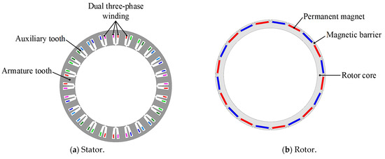
Figure 1.
Topology of proposed PMSM. (a) Stator. (b) Rotor.

Figure 2.
Winding connection.

Table 1.
Design dimensions and structure parameters of proposed PMSM.

Table 2.
Material data of PMSM.
3. High-Reliability Design
3.1. Dual Three-Phase Winding
The conventional double-layer, three-phase winding structure is associated with drawbacks such as a low winding coefficient and large torque ripple. In order to satisfy the high reliability and high-efficiency requirements of the flywheel energy-storage system, a dual three-phase stator winding is adopted in the PMSM. Different winding structures and slot vector star diagrams are solved by finite-element analysis, as shown in Figure 3. A high winding factor and low harmonics are crucial considerations in selecting the winding topology. However, an excessive number of phases will complicate machine control and lead to additional switching losses. Therefore, after careful consideration, a dual three-phase winding with a 30° phase difference is selected. Due to the dual three-phase winding structure, the fundamental winding factor and torque density of the PMSM are effectively improved.
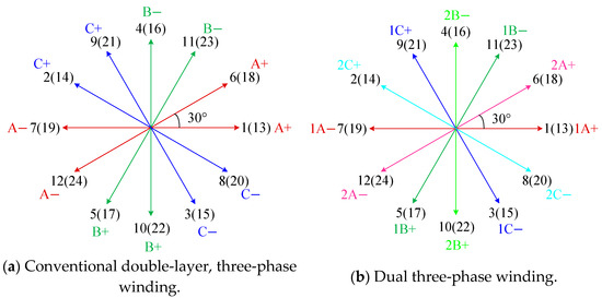
Figure 3.
Different winding structures and slot vector star diagrams. (a) Conventional double-layer, three-phase winding. (b) Dual three-phase winding.
The stator magnetomotive force distributions generated by each set of windings separately in the dual three-phase winding structure are solved by finite-element analysis, as shown in Figure 4. It can be seen that the amplitude of the magnetomotive force remains consistent across each set of windings. The two sets of windings are completely independent. However, there exists a phase difference between each set of windings. Moreover, the stator magnetomotive force distributions under the conventional three-phase winding and dual three-phase winding are solved by finite-element analysis and compared, as shown in Figure 5. It is evident that the magnetomotive force distributions are different, resulting in distinct harmonic content. Due to the double redundant winding structure of the dual three-phase winding, the fault-tolerant operation of the PMSM under a set of open-circuit winding faults can be ensured. As a result, the reliability of the PMSM is greatly improved. Additionally, Fourier decomposition is performed on the stator magnetomotive force distributions, and the results are compared, as shown in Figure 6. It is apparent that the dual three-phase winding significantly enhances the fundamental content while effectively reducing subharmonic content through the phase compensation between the two sets of windings. The high content of low-order harmonics is one of the main sources of eddy current losses. The dual three-phase winding structure almost completely eliminates the second harmonic, resulting in a significant reduction in eddy loss for the PMSM.
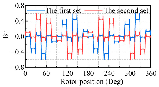
Figure 4.
Stator magnetomotive force distributions generated by each set of windings.

Figure 5.
Stator magnetomotive force distributions under the different winding structures. (a) Conventional double-layer three-phase winding. (b) Dual three-phase winding.
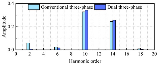
Figure 6.
Harmonic order of stator magnetomotive force distributions.
3.2. Design of Auxiliary Teeth
The degree of phase-to-phase coupling refers to the ratio of inductance between adjacent two-phase windings, assessing the electromagnetic correlation between the two-phase windings. The self-inductance and mutual inductance can be expressed as
where θ is the mechanical angle of the PMSM, μ0 is the vacuum permeability, r is the radius of the effective air gap, l is the axial length of the PMSM, and NA(θ) is the winding function.
Reducing the coupling between windings in each phase of the PMSM can significantly decrease the risk of total system failure in the flywheel energy-storage system. The degree of phase-to-phase coupling mc can be expressed as
where LAA is the self-inductance of phase A windings, and LAB is the mutual inductance between phase A windings and phase B windings. The degree of phase-to-phase coupling of the PMSM is calculated as 23%.
In order to reduce the degree of phase-to-phase coupling, a design of auxiliary teeth is conducted on the stator of the PMSM. The size of the stator auxiliary teeth has a significant impact on the self-inductance and mutual inductance of the windings, thereby reducing short-circuit current. Combined with the dual three-phase winding structure, the stator auxiliary teeth can improve the reliability and ensure the electromagnetic performance of the PMSM. Due to the adoption of a parallel tooth structure in the stator, the space in the stator slot is trapezoidal. Therefore, the trapezoidal auxiliary teeth are selected to reserve enough space for the windings and ensure the slot filling rate of the PMSM. The size of the auxiliary teeth is shown in Figure 7. It is evident that the length of the auxiliary teeth is La, and the width of the auxiliary teeth is Wa. The size of the stator auxiliary teeth can be optimized to suppress the short-circuit current and enhance the reliability of the PMSM.
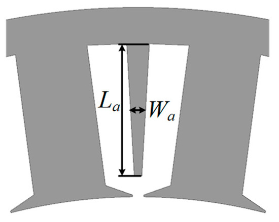
Figure 7.
Size of the auxiliary teeth.
The variation of self-inductance and mutual inductance with respect to the length of the auxiliary teeth La is shown in Figure 8. It can be seen that La is optimized in a range from 25 to 39 mm for the design requirements under consideration. Additionally, it is apparent that the length of the auxiliary teeth La has a huge influence on the self-inductance and mutual inductance of the PMSM. The increasing La results in a decrease in the degree of phase-to-phase coupling. When the length of the auxiliary teeth exceeds 35 mm, the degree of phase-to-phase coupling can be reduced to less than 14%. Considering the depth of the stator slot, the length of the auxiliary teeth La is selected to be 35 mm.
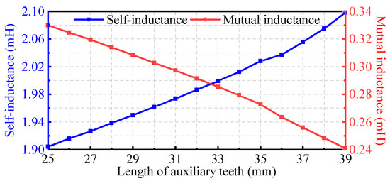
Figure 8.
Variation of self-inductance and mutual inductance with length of auxiliary teeth.
In order to evaluate the effect of the width of the auxiliary teeth Wa on the degree of phase-to-phase coupling, the variation of self-inductance and mutual inductance with respect to the width of the auxiliary teeth Wa was determined and is depicted in Figure 9. It is evident that as the width of the auxiliary teeth increases, the self-inductance increases while the mutual inductance decreases. Moreover, the width of the auxiliary teeth has a significant impact on the short-circuit current and performance of the PMSM. Additionally, in the auxiliary teeth design, the width of the stator teeth decreases as the size of the auxiliary teeth increases, ensuring the groove area remains consistent. As a result, the slot fill rate and current density are kept constant. The short-circuit current and torque with varying widths of the auxiliary teeth are solved by finite-element analysis, as shown in Figure 10. It is apparent that the short-circuit current and torque decrease approximately linearly with the increasing width of the auxiliary teeth. However, the torque reduction shows slight fluctuations. Therefore, it is important to avoid a significant drop of the torque. Notably, when the width of the auxiliary teeth exceeds 4 mm, there is a marked decrease in torque. It is necessary to reduce the short-circuit current while reducing the impact on torque. Consequently, the width of the auxiliary teeth Wa was selected to be 4 mm.
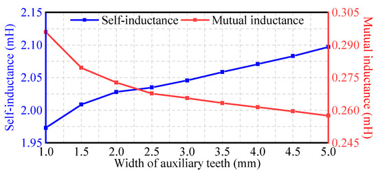
Figure 9.
Variation of self-inductance and mutual inductance with width of auxiliary teeth.
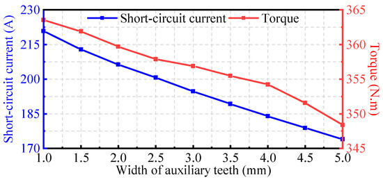
Figure 10.
Variation of short-circuit current and torque with width of auxiliary teeth.
The short-circuit current reaches a steady-state value when the magnetic flux in the short-circuit winding is minimal. Conversely, the short-circuit current reaches a transient value when the magnetic flux in the short-circuit winding is maximum. The steady state and peak short-circuit current of the PMSM were compared both with and without the auxiliary teeth, as shown in Figure 11. The simulation results show that the steady state and peak short-circuit current of the PMSM with the auxiliary teeth are lower than those of the PMSM without the auxiliary teeth. Due to the adoption of the auxiliary teeth, the steady-state short-circuit current decreases from 123 A to 90 A, and the peak short-circuit current decreases from 234 A to 183 A, representing reductions of 27% and 22%, respectively. Additionally, the torque of the PMSM both with and without the auxiliary teeth are solved by finite-element analysis, as listed in Table 3. The adoption of the auxiliary teeth results in a decrease in average torque from 368 N·m to 354 N·m, accompanied by an increase in torque ripple from 2.6% to 2.9%. Therefore, the reliability of the PMSM is greatly improved while ensuring torque performance.

Figure 11.
Comparison of short-circuit current of PMSM. (a) Peak short-circuit current. (b) Steady state short-circuit current.

Table 3.
Torque performance of PMSM both with and without auxiliary teeth.
4. Performance Analysis
Based on the dual three-phase stator winding structure and auxiliary teeth, the final finite-element model of the PMSM is determined. Therefore, the electromagnetic performance of the proposed highly reliable PMSM can be calculated and analyzed. The no-load back electromotive force of the PMSM and corresponding harmonic orders are solved by finite-element analysis, as shown in Figure 12. It can be observed that the peak of the no-load back electromotive force is 463 V at a speed of 3500 rpm. The no-load back electromotive force coefficient is 0.132 V/rpm. The no-load back electromotive force waveform appears predominantly sinusoidal. However, due to an abundant third harmonic content, the no-load back electromotive force waveform exhibits a flat-top wave.

Figure 12.
Back electromotive force of PMSM. (a) Back electromotive force waveform. (b) Harmonic orders.
Figure 13 depicts the waveforms of self-inductance and mutual inductance for the PMSM. The average self-inductance is 2.11 mH, while the average mutual inductance is 0.26 mH. The degree of phase-to-phase coupling of the PMSM without auxiliary teeth is calculated as 23%. However, the phase-to-phase coupling for the PMSM with auxiliary teeth is only 12%, indicating a significant improvement in reliability. Moreover, the torque performance of the PMSM is solved by finite-element analysis, as shown in Figure 14. It is evident that the cogging torque of the PMSM is 4 N·m, while the average torque reaches 354 N·m. The torque ripple is only 2.9%. Due to the dual three-phase stator winding structure, the torque ripple is significantly reduced. Moreover, the design of auxiliary teeth has little impact on the torque performance of the PMSM. Consequently, the dual three-phase stator winding structure and auxiliary teeth ensure electromagnetic performance and significantly enhance the reliability of the PMSM.
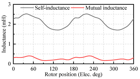
Figure 13.
Self-inductance and mutual inductance of PMSM.

Figure 14.
Torque performance of PMSM. (a) Cogging torque. (b) Torque.
Additionally, mechanical stress and deformation analysis were performed to check the mechanical strength of the PMSM. The rotor core is the main stressed part. Therefore, the mechanical stress and deformation of the rotor core were analyzed, as shown in Figure 15. It can be seen that the maximum mechanical stress is 61 MPA, which is less than the tensile strength of the silicon steel material. The maximum deformation induced by the centrifugal force is only 0.008 mm. Therefore, the rotor core made of silicon steel has sufficient mechanical strength to withstand the centrifugal force and maintain operational stability.
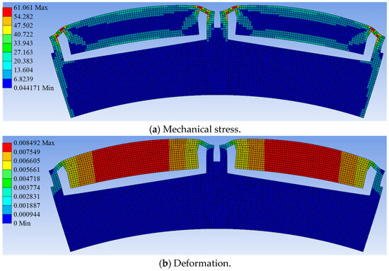
Figure 15.
Mechanical stress and deformation of rotor core. (a) Mechanical stress. (b) Deformation.
5. Experimental Validation
Based on the theoretical analysis above, the proposed highly reliable PMSM can be built and tested. Figure 16 shows the photographs of the stator and rotor. The dual three-phase stator winding structure with a 30° phase difference was adopted on the stator. In order to reduce iron loss, the stator of the PMSM was made of thin silicon steel sheets. Meanwhile, the permanent magnets were arranged within the rotor slots and manufactured in an axial segmented structure to reduce eddy loss. Magnetic barriers were implemented between adjacent permanent magnets to mitigate the effect of magnetic flux leakage. The built-in rotor eliminates the requirement for a sheath, simplifying the manufacture and assembly of the PMSM. The experimental platform is shown in Figure 17, including the controller and machine. The no-load back electromotive force waveform of the PMSM is measured and shown in Figure 18a. It can be seen that the measured back electromotive force waveform appears predominantly sinusoidal. The peak of the back electromotive force is 455 V, and the back electromotive force coefficient is 0.13 V/rpm. Figure 18b compares the experimental and simulated values of the no-load back electromotive force at various speeds. The simulated back electromotive force coefficient is 0.132 V/rpm, which closely matches the measured value, indicating the rationality of the prototype manufacturing and design.
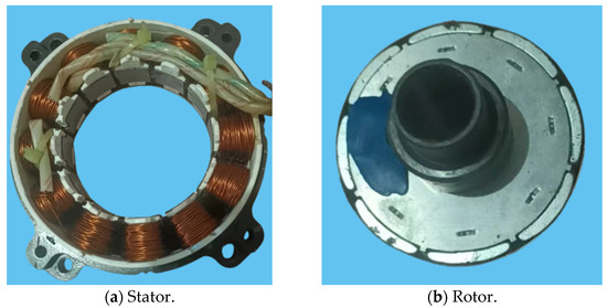
Figure 16.
Prototype. (a) Stator. (b) Rotor.
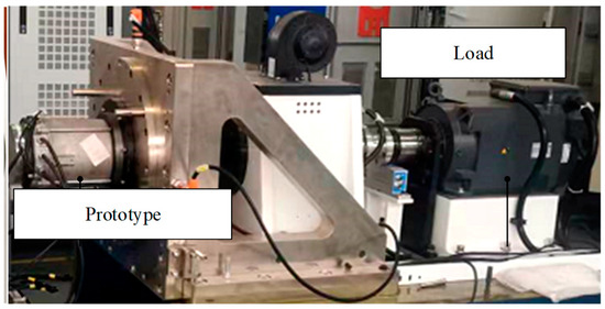
Figure 17.
Experimental platform.

Figure 18.
Comparison of experimental and simulated results. (a) Back electromotive force of prototype. (b) Comparison of back electromotive force coefficient.
Since the PMSM used in the experimental platform lacks a water-cooled sleeve, only low-load experiments can be conducted. The low-load experimental waveforms are measured and shown in Figure 19. The blue line represents the electrical angle of the PMSM at 0.3663 V/rad. The red line shows the bus current, the yellow line indicates the bus voltage, and the green line corresponds to the phase A current. The electrical angle, bus current, bus voltage, and phase A current waveforms of the PMSM were measured. Under the steady-state conditions, the bus voltage was maintained at 600 V, the bus current was 15 A, and the peak-to-peak fluctuation of the bus voltage was 5 V. The phase current shows distortion, with a large third harmonic content.
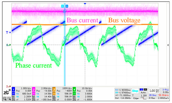
Figure 19.
Low-load experimental waveform.
6. Conclusions
In this article, a highly reliable PMSM was proposed for flywheel energy-storage systems. The main contribution of the proposed PMSM was to enhance reliability while ensuring electromagnetic performance. A comparison and analysis were conducted between the conventional double-layer, three-phase winding structure and the dual three-phase stator winding structure. The results indicate that the double redundant winding structure ensures fault-tolerant operation of the PMSM. Moreover, the stator was designed with auxiliary teeth to reduce the short-circuit current. This reduction effectively lowers the temperature and mitigates the risk of melting during a winding short circuit, thereby enhancing the reliability. Moreover, the electromagnetic performance and mechanical stress were analyzed. A prototype was built and tested, and the measured and simulated back electromotive force coefficient were in good agreement, indicating the rationality of the prototype manufacturing and design. Due to the limitations of the experimental platform, only low-load waveforms were measured. The bus voltage was maintained at 600 V, the bus current was 15 A, and the peak-to-peak fluctuation of the bus voltage was 5 V. The phase current exhibited distortion with a significant third harmonic content.
Author Contributions
Methodology, F.L.; validation, Z.Z.; writing—original draft preparation, X.J.; writing—review and editing, X.J. and L.Z.; visualization, X.J.; supervision, L.Z. All authors have read and agreed to the published version of the manuscript.
Funding
This research received no external funding.
Data Availability Statement
The data presented in this study are available on request from the corresponding author. The data are not publicly available due to privacy restrictions.
Conflicts of Interest
The authors declare no conflict of interest.
References
- Alkuhayli, A.; Noman, A.M.; Al-Shamma’a, A.A.; Abdurraqeeb, A.M.; Alharbi, M.; Hussein Farh, H.M.; Qamar, A. Enhancing photovoltaic-powered DC shunt motor performance for water pumping through fuzzy logic optimization. Machines 2024, 12, 442. [Google Scholar] [CrossRef]
- Montoya, O.D.; Gil-González, W.; Hernández, J.C. Optimal Scheduling of Photovoltaic Generators in Asymmetric Bipolar DC Grids Using a Robust Recursive Quadratic Convex Approximation. Machines 2023, 11, 177. [Google Scholar] [CrossRef]
- Kang, J.; Lee, J.; Ham, S.; Chun, Y.; Kim, H. A study on new straight shape design to reduce cogging torque of small wind power generator. Machines 2024, 12, 412. [Google Scholar] [CrossRef]
- Huang, Y.; Chen, H.; Dai, J.; Tao, H.; Wang, X. Working condition identification method of wind turbine drivetrain. Machines 2023, 11, 495. [Google Scholar] [CrossRef]
- Tinnawat, H.; Matthew, O.T.C.; Chakkapong, C.; Ziv, B. Control system design for low power magnetic bearings in a flywheel energy storage system. Energy Eng. 2023, 120, 147–161. [Google Scholar]
- Murayama, M.; Kato, S.; Tsutsui, H.; Tsuji-Iio, S.; Shimada, R. Combination of flywheel energy storage system and boosting modular multilevel cascade converter. IEEE Trans. Appl. Supercond. 2018, 28, 1–4. [Google Scholar] [CrossRef]
- Abdeltawab, H.H.; Mohamed, Y.A.-R.I. Robust energy management of a hybrid wind and flywheel energy storage system considering flywheel power losses minimization and grid-code constraints. IEEE Trans. Ind. Electron. 2016, 63, 4242–4254. [Google Scholar] [CrossRef]
- Liu, Z.Q.; Wang, K.; Li, F. Design and analysis of permanent magnet homopolar machine for flywheel energy storage system. IEEE Trans. Magn. 2019, 55, 1–6. [Google Scholar] [CrossRef]
- Ye, C.; Yang, J.; Xu, W.; Xiong, F.; Liang, X. A novel multi-unit out-rotor homopolar inductor machine for flywheel energy storage system. IEEE Trans. Magn. 2018, 54, 1–5. [Google Scholar] [CrossRef]
- Li, X.; Anvari, B.; Palazzolo, A.; Wang, Z.; Toliyat, H. Autility-scale flywheel energy storage system with a shaftless, hubless, high-strength steel rotor. IEEE Trans. Ind. Electron. 2018, 65, 6667–6675. [Google Scholar] [CrossRef]
- Xu, M.; Zhao, W.; Ji, J.; Chen, Q.; Liu, G. Auxiliary notching rotor design to minimize torque ripple for interior permanent magnet machines. IEEE Trans. Ind. Electron. 2024, 71, 12051–12062. [Google Scholar] [CrossRef]
- Ling, Z.; Zhao, W.; Ji, J.; Xu, M.; Sun, Y.; Hu, Q. Performance improvement in a linear primary permanent magnet vernier machine by modular unit shift effect. IEEE Trans. Transport. Electrific. 2023, 9, 4562–4570. [Google Scholar] [CrossRef]
- Ye, C.; Yu, D.; Liu, K.; Dai, Y.; Deng, C.; Yang, J.; Zhang, J. Research of a stator PM excitation solid rotor machine for flywheel energy storage system. IEEE Trans. Ind. Electron. 2022, 69, 12140–12151. [Google Scholar] [CrossRef]
- Li, W.; Chau, K.T.; Ching, T.W.; Wang, Y.; Chen, M. Design of a high-speed superconducting bearingless machine for flywheel energy storage systems. IEEE Trans. Appl. Supercond. 2015, 25, 1–4. [Google Scholar] [CrossRef]
- Kim, J.; Lee, J.; Kim, H. A comparative study of pole–slot combination with fractional slot concentrated winding in outer rotor permanent magnet synchronous generator for hybrid drone system. Machines 2024, 12, 464. [Google Scholar] [CrossRef]
- Shah, S.H.; Wang, Y.-C.; Shi, D.; Shen, J.-X. Investigation of torque and reduction of torque ripples through assisted-poles in low-speed, high-torque density spoke-type PMSMs. Machines 2024, 12, 327. [Google Scholar] [CrossRef]
- Ling, Z.; Zhao, W.; Sun, Y.; Ji, J.; Xu, M. Characteristic analysis and harmonic function validation of 3-D modulation effect for magnetic lead screw transmission. IEEE Trans. Transport. Electrific. 2024; early access. [Google Scholar] [CrossRef]
- Oukrid, M.; Bernard, N.; Benkhoris, M.-F.; Ziane, D. Design and optimization of a five-phase permanent magnet synchronous machine exploiting the fundamental and third harmonic. Machines 2024, 12, 117. [Google Scholar] [CrossRef]
- El Hajji, T.; Hlioui, S.; Louf, F.; Gabsi, M.; Mermaz-Rollet, G.; Belhadi, M. Optimal design of high-speed electric machines for electric vehicles: A case study of 100 kW V-shaped interior PMSM. Machines 2023, 11, 57. [Google Scholar] [CrossRef]
- Wang, J.; Geng, W.; Li, Q.; Li, L.; Zhang, Z. A new flux-concentrating rotor of permanent magnet motor for electric vehicle application. IEEE Trans. Ind. Electron. 2022, 69, 10882–10892. [Google Scholar] [CrossRef]
- Kefalas, T.D.; Kladas, A.G. Thermal investigation of permanent-magnet synchronous motor for aerospace applications. IEEE Trans. Ind. Electron. 2014, 61, 4404–4411. [Google Scholar] [CrossRef]
- Hezzi, A.; Ben Elghali, S.; Bensalem, Y.; Zhou, Z.; Benbouzid, M.; Abdelkrim, M.N. ADRC-based robust and resilient control of a 5-phase PMSM driven electric vehicle. Machines 2020, 8, 17. [Google Scholar] [CrossRef]
- Meng, S.; Ling, Z.; Zhao, W.; Ji, J.; Xu, M. Design and analysis of a surface-inserted magnetic screw with minimum thrust force ripple. IEEE Trans. Transport. Electrific. 2024; early access. [Google Scholar] [CrossRef]
- Ling, Z.; Zhao, W.; Rasmussen, P.O.; Ji, J.; Jiang, Y.; Liu, Z. Design and manufacture of a linear actuator based on magnetic screw transmission. IEEE Trans. Ind. Electron. 2021, 68, 1095–1107. [Google Scholar] [CrossRef]
- Ling, Z.; Meng, S.; Zhao, W.; Ji, J.; Xu, M. Analysis and design of a high force low torque ratio magnetic field modulation screw. IEEE Trans. Ind. Electron. 2024, 71, 14620–14630. [Google Scholar] [CrossRef]
- Zhou, Y.; Li, Y.; Lv, Q.; Lv, D.; Yang, Y.; Zheng, J. Investigation of a high speed permanent magnet synchronous machine for magnetic suspended flywheel energy storage system. In Proceedings of the 2020 IEEE 4th Conference on Energy Internet and Energy System Integration, Wuhan, China, 30 October–1 November 2020; pp. 2733–2737. [Google Scholar]
- Sun, M.; Xu, Y.; Han, K. Structure and optimization design of cup winding permanent magnet synchronous machine in flywheel energy storage system. IEEE Trans. Magn. 2023, 59, 1–5. [Google Scholar] [CrossRef]
- Qi, Y.; Bostanci, E.; Gurusamy, V.; Akin, B. A comprehensive analysis of short-circuit current behavior in PMSM interturn short-circuit faults. IEEE Trans. Power Electron. 2018, 33, 10784–10793. [Google Scholar] [CrossRef]
- Wan, Y.; Meng, N.; Jia, Y.; Zhu, L. Research on interturn short-circuit characteristic of the high-speed permanent-magnet machine with gramme-ring windings. IEEE Trans. Magn. 2022, 58, 1–6. [Google Scholar] [CrossRef]
- Dusek, J.; Arumugam, P.; Brunson, C.; Amankwah, E.K.; Hamiti, T.; Gerada, C. Impact of slot/pole combination on inter-turn short-circuit current in fault-tolerant permanent magnet machines. IEEE Trans. Magn. 2016, 52, 1–9. [Google Scholar] [CrossRef]
Disclaimer/Publisher’s Note: The statements, opinions and data contained in all publications are solely those of the individual author(s) and contributor(s) and not of MDPI and/or the editor(s). MDPI and/or the editor(s) disclaim responsibility for any injury to people or property resulting from any ideas, methods, instructions or products referred to in the content. |
© 2024 by the authors. Licensee MDPI, Basel, Switzerland. This article is an open access article distributed under the terms and conditions of the Creative Commons Attribution (CC BY) license (https://creativecommons.org/licenses/by/4.0/).