Abstract
This study presents a comprehensive geometric modeling and error propagation analysis for a 3-degrees-of-freedom spindle head, focusing on an over-constrained parallel mechanism. Four geometric error models are established for the over-constrained spindle head, each considering different combinations of constraint wrenches. A set of sensitivity indices is formulated to evaluate the effectiveness of these models. Comparative sensitivity analysis suggests that a model incorporating all constraint wrenches is suitable for error propagation analysis. Two error propagation indices are introduced to quantify the impact of the geometric source errors on the position and orientation of an individual limb structure. The coupled error propagation indices account for the kinematic interactions among limb structures, allowing for a detailed analysis of the spindle head’s terminal accuracy. The relative deviations of error propagation indices are utilized to assess the quantitative impact of kinematic interactions on the geometric errors of an individual limb structure. Furthermore, this study analyzes the cumulative effects of kinematic errors from three limb structures to reflect the influence of kinematic interactions on the terminal accuracy of the spindle head. The findings indicate that geometric errors of the limbs in such an over-constrained spindle head are mutually compensatory, reducing linear and angular errors and enhancing the spindle head’s terminal accuracy.
1. Introduction
The over-constrained parallel mechanism is a type of closed-loop mechanism with linearly dependent constraint forces/torques [1]. The over-constrained nature of such parallel mechanisms endows them with compact structure, excellent stiffness, and dynamic performance [2,3,4]. Moreover, compared to non-over-constrained parallel mechanisms with the same mobility, over-constrained parallel mechanisms often have fewer kinematic joints, resulting in fewer sources of geometric errors and potentially achieving superior kinematic accuracy [5,6]. Taking the over-constrained Exechon parallel mechanism as an example, it realizes three-degrees-of-freedom motion, including one translation and two rotations, through 13 equivalent single-degree-of-freedom joints [7,8]. This mechanism has been successfully integrated as a key spindle head with modules and guide rails and applied to high-performance milling or drilling processes for complex aerospace structural components such as aircraft wall panels, floors, and skins [9,10].
However, there are two sides to every coin. While the over-constrained nature allows parallel mechanisms to achieve compact structures and minimize sources of geometric errors, thereby enhancing their potential motion accuracy to a certain extent, ensuring strict linear correlation among the over-constrained forces/torques is essential for achieving the desired kinematic performance [11]. This requirement not only imposes stringent demands on the manufacturing and assembly precision of the components of over-constrained parallel mechanisms but also renders these mechanisms highly sensitive to perturbations from geometric errors of the components [12,13], to some extent restricting their kinematic accuracy. From the perspective of improving the kinematic accuracy of over-constrained parallel mechanisms, it is crucial to fully consider the interactive effects of the over-constrained forces/torques on the motion performance of the mechanism and establish appropriate geometric error models and conduct proper kinematic error assessments. This is also one of the key foundations for the practical application of over-constrained parallel mechanisms.
There are various methods for the geometric error modeling of parallel mechanisms, including Denavit–Hartenberg (D-H) parameterized matrices [14], the product of exponential (POE) formula [15,16], the screw method [17,18], and others. Ni et al. established an error model of a 1T2R parallel mechanism, improving the error compensation effect by improving the properties of the error identification matrix [19]. Luo et al. proposed an error model of DiaRoM-II with a dimensionless error mapping matrix [20]. Mei et al. analyzed the constraint and drive wrench of a five-axis parallel machining robot to establish its error model, realizing the error identification and compensation [21]. Chen et al. used the POE method to establish the error model of the limbs; then, they were rewritten into the form of a full rank matrix to obtain an error model of the manipulator [22]. However, none of these geometric error modeling methods can comprehensively and efficiently adapt to the diverse types of parallel mechanisms. Therefore, researchers need to adapt these methods effectively based on the structural characteristics of the specific parallel mechanism under study. These error modeling methods are mainly completed by eliminating passive error through projection after establishing an error model for the limbs [23]. For the redundant mechanism, a redundant wrench and a constraint wrench are introduced, resulting in nonlinear deformation of the mechanism. Non-redundant constraints are simply expressed by a full rank matrix [24,25]. Moreover, Shen et al. proposed a Markov data-based approach to address the long-standing challenge of modeling complex tensegrity systems, which could provide significant help in robots with tensegrity structures [26]. Furthermore, for over-constrained parallel mechanisms, the difficulty in geometric error modeling lies not only in selecting suitable modeling methods but also in fully considering the linearly dependent constraint forces/torques.
Based on geometric error modeling, the key to conducting kinematic error assessment lies in constructing concise and physically meaningful performance indicators for kinematic errors. Volume errors are often used to evaluate the distribution of terminal errors in the workspace. Stiffness is a key parameter which affects accuracy. Ye et al. estimated the deformation errors based on the robot stiffness model and defined a contour error based machining performance index [27]. Chen et al. proposed a normal stiffness performance index to evaluate the stiffness performance and optimized tool feed direction [28]. Sensitivity indices are widely used to reveal the influence of source errors on the terminal error [29]. Based on the error model of a new five-degrees-of-freedom parallel robot, Luo et al. identified important and secondary source errors through sensitivity analysis [30]. Wu et al. conducted sensitivity analysis on a novel grinding device using the Monte Carlo method based on the Sobol sequence [31]. Li et al. established a low-error-sensitivity workspace index based on sensitivity analysis to evaluate the error characteristics of parallel mechanisms [32]. Dexterity is also an index used to measure the accuracy of a robot. Shi et al. analyzed the dexterity for the 4UPS-RRR parallel ankle rehabilitation mechanism through the establishment of its Jacobian matrix [33]. Wang et al. analyzed the working space and dexterity of the robot and discovered the optimal length distributions for two-segment and three-segment continuum robots [34]. Nabavi et al. used dexterity, kinetic energy, and a new modified workspace index for optimal determination of the remaining parameters [35]. Overall, the existing kinematic error performance indicators are mostly constructed using the geometric error propagation matrix and its eigenvalues and often only focus on the kinematic performance at the mechanism level, neglecting the geometric error propagation characteristics between the limb structures. In other words, for over-constrained parallel mechanisms with complex linearly dependent constraint forces/torques between limbs, how to consider not only the mechanical system level but also the limb structural level in constructing suitable performance indices for kinematic error is still a challenge that needs to be addressed.
With the above-mentioned problem in mind, the present study will take an over-constrained spindle head as an example on which carry out the geometric modeling and error propagation analysis. For this purpose, the rest of this paper is organized as follows: Section 2 establishes the four forms of geometric error modeling with the various combination of the constraint wrenches. A set of sensitivity indices are formulated to evaluate four types of geometric error models. In Section 3, a set of error propagation indices and coupled error propagation indices are proposed to analyze the error propagation at both the limb structural level and the mechanical system level, respectively. Then, the influence pattern of the kinematic interactions between the limbs on the terminal accuracy can be revealed, and some suggestions for structural design are proposed to enhance the terminal accuracy of the spindle head. Finally, some conclusions and remarks are presented in Section 4.
2. Geometric Error Modeling and Comparison of Individual Limbs
The design process of spindle head mainly includes three steps: structure and dimension design, accuracy synthesis, and kinematic calibration of prototype. Among them, geometric error modeling plays an important role. It can reflect the mapping relationship between source errors and terminal error, not only providing important theoretical support for tolerance design and assembly of parts but also providing an important basis for kinematic calibration.
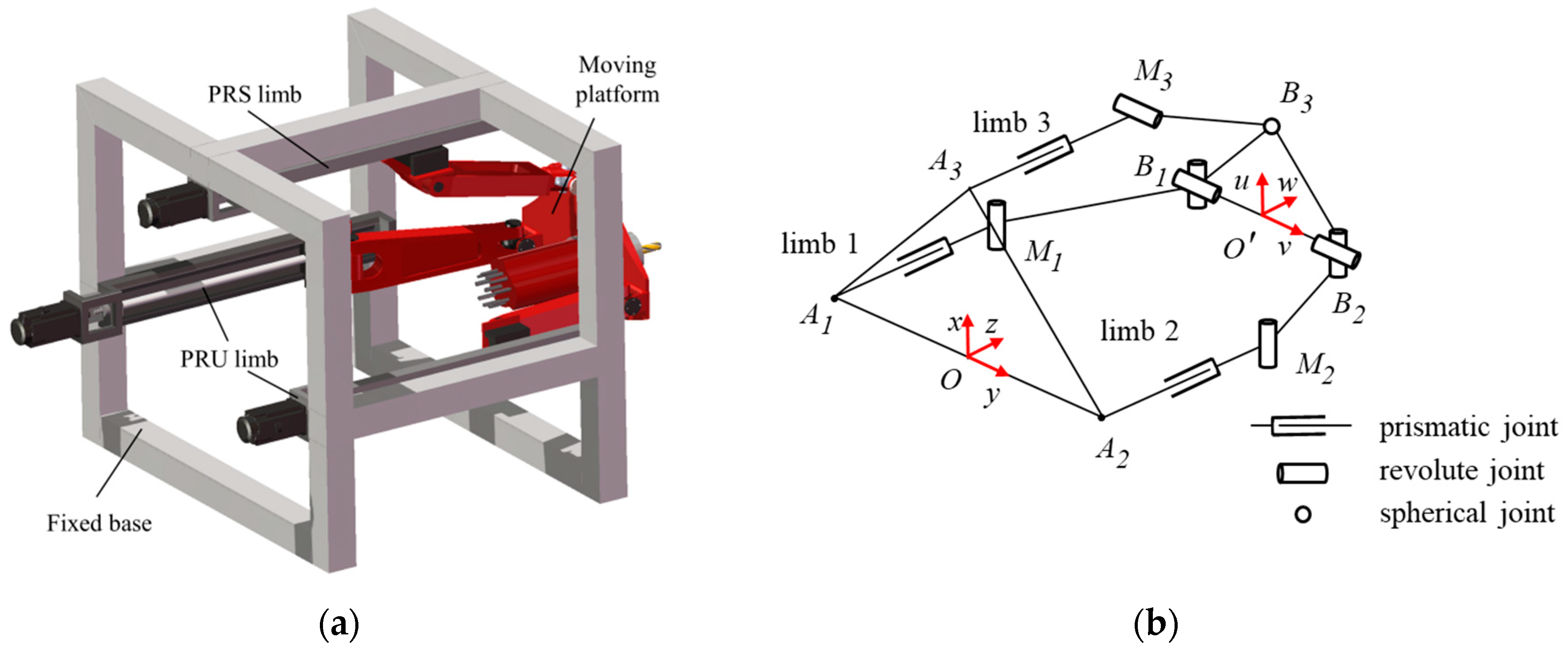
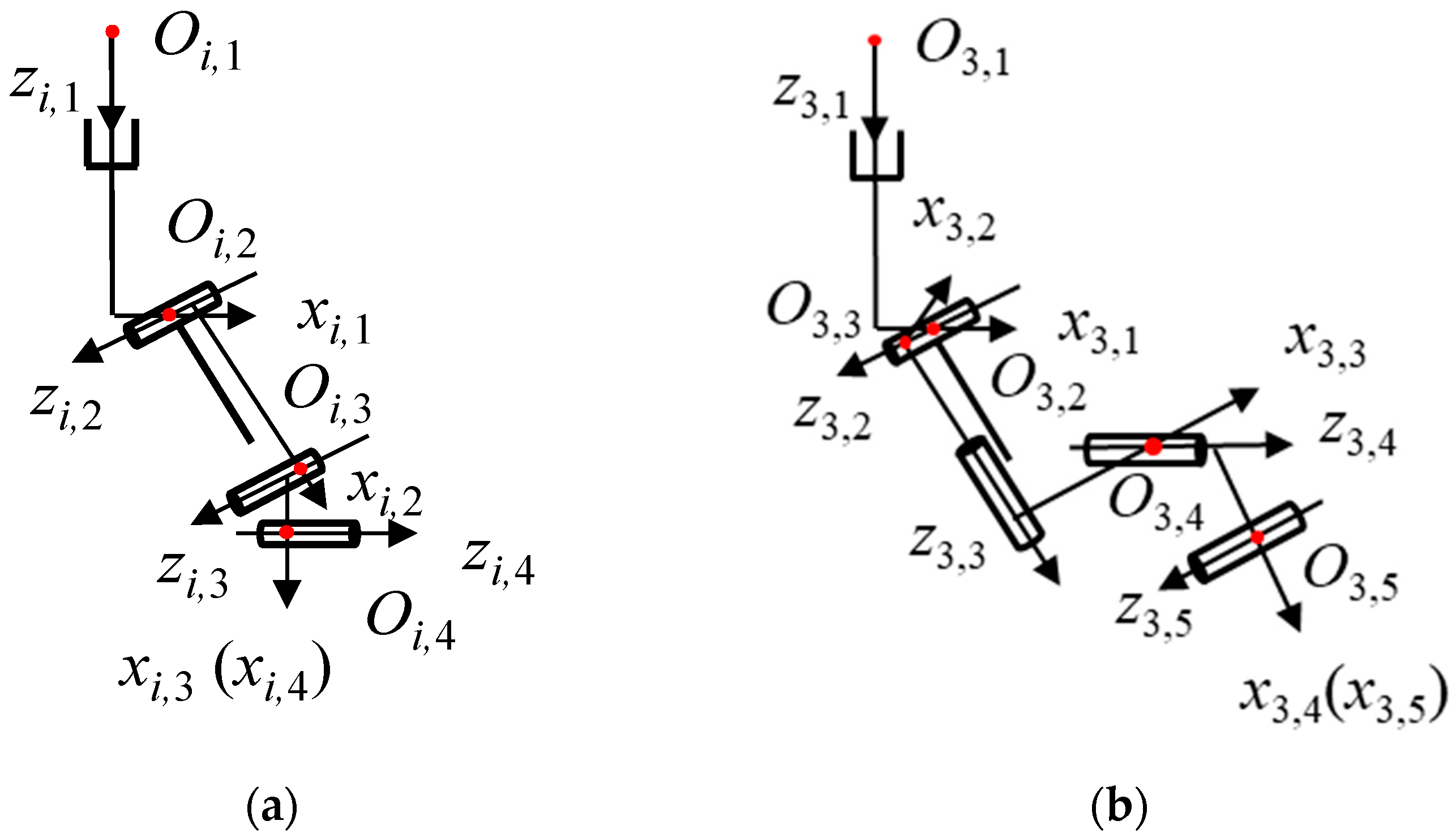
2.1. Structure Description and Coordinates Settings
In this section, a 3-degrees-of-freedom (DOF) spindle head is taken as an example to demonstrate the geometric error modeling process. The prototype model and schematic diagram of the spindle head are shown in Figure 1.
Figure 1.
Prototype model and schematic diagram of the 3-DOF spindle head: (a) prototype model; (b) schematic diagram.
As can be seen from Figure 1, the 3-DOF spindle head is with the topological architecture of 2PRU-1PRS (“R”, “U”, “S”, and “P” represent revolute joint, universal joint, spherical joint, and actuated prismatic joint, respectively). To be specific, the spindle head mainly consists of two PRU limbs, a PRS limb, a moving platform, and a fixed base. Limb 1 and limb 2 are two symmetrically distributed PRU limbs; limb 3 is a PRS limb. Ai and Bi (i = 1, 2, 3) represent the intersections of the ith limb connected to the fixed base and the moving platform, respectively. Mi is the geometric center of a revolute joint in the ith limb. With these structural arrangements, the spindle head can perform three-axis synchronization motions and then be integrated into a hybrid kinematic machining center for multi-axis high-speed machining of components with complex geometries. To determine the physical spindle head setup, the following parameters are defined: the length of is called the radius of the stationary platform (ra); the length of is called the length of the connecting rod (a); and the length of is called the radius of the moving platform (rb). The dimension parameters of spindle head are shown in Table 1.
Table 1.
The physical setup of the 3-DOF spindle head.
For derivation facility, the following frames are defined. The fixed coordinate system is attached to the fixed base with at the center of A1A2, in which the z axis is perpendicular to the ΔA1A2A3, the axis is coincident with the vector of , and the y axis is decided by the right-hand rule. The reference coordinate system is attached to the moving platform with at the center of , in which the w axis is perpendicular to the plane of , the u axis is coincident with the vector of , the v axis is decided by the right-hand rule. Moreover, the local coordinate systems of individual limbs are depicted in Figure 2. Herein, is defined as the local coordinate system for the jth joint in the ith limb. is along with the jth joint axis; coincides with the common normal of and ; overlaps with ; is the intersection of and ; and the axis can be defined by the right hand rule. Meanwhile, the frame is considered as the local coordinate system of 0th joint, and the frame is considered as the last local coordinate system for each limb.
Figure 2.
Local coordinate systems of individual limbs: (a) the PRU limb; (b) the PRS limb.
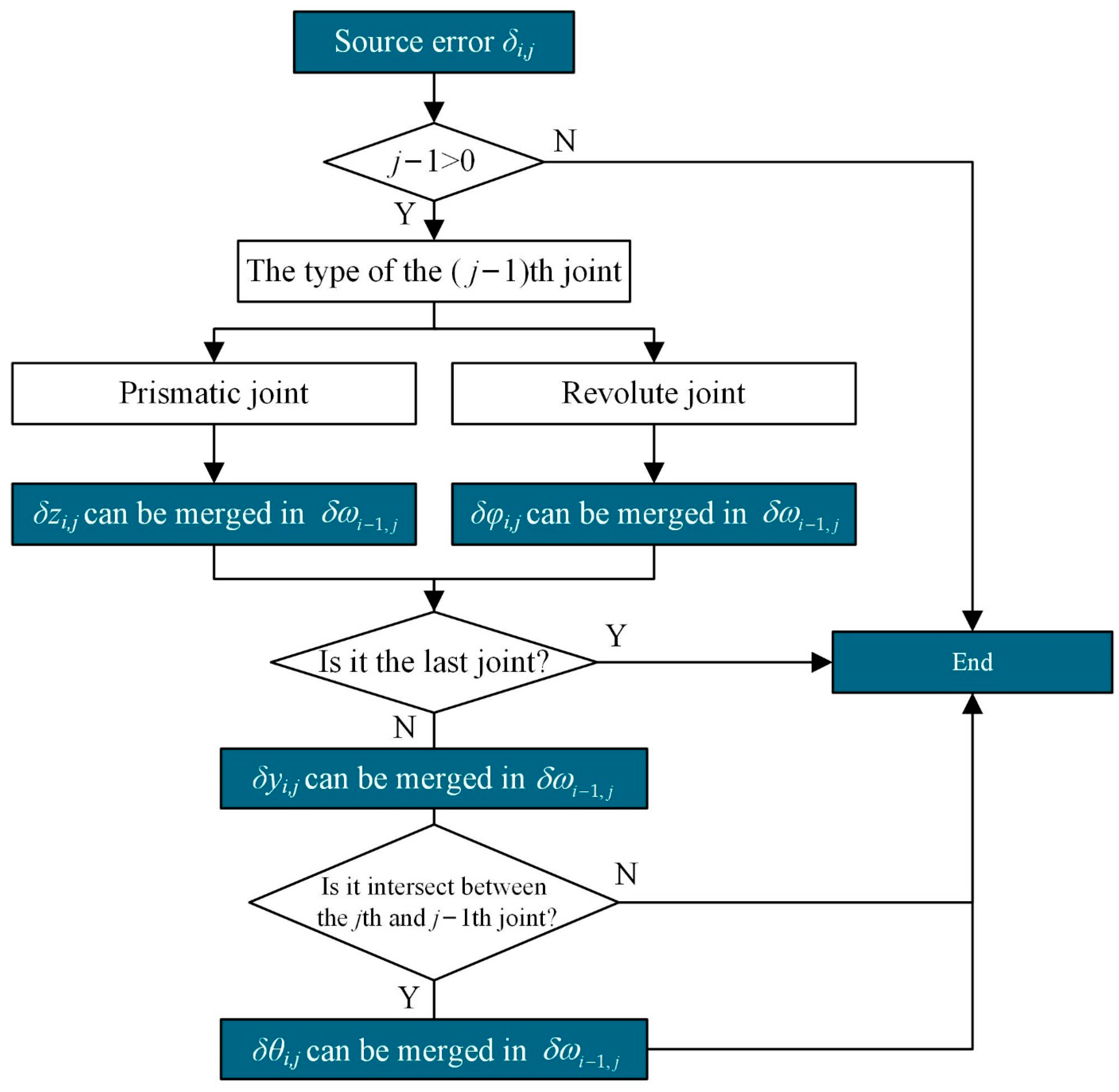
2.2. Error Modeling of Individual Limbs
According to the structure of the spindle head, a “U” joint or an “S” joint can be equivalent into two or three orthogonally arranged single-DOF joints. Thus, considering such a joint structure, the source errors of the jth joint in the ith limb can be expressed as follows:
where ,, and represent the position source errors in the frame ;, , and represent the orientation source errors in the frame .
To simplify the error modeling, redundant source errors in a limb structure can be merged. To be specific, when the (j − 1)th joint is a prismatic joint, can be merged into ; when the (j − 1)th joint is a revolute joint, can be merged into ; when the (j − 1)th joint is not the last joint, is not included in the transformation. Moreover, if the (j − 1)th joint is not a prismatic joint and the motion axes of the (j − 1)th joint intersect with the jth joint, cannot be included in the transformation. Following the elimination process, depicted as Figure 3, the simplified source errors of the three limbs can be obtained and expressed as follows.
Figure 3.
Elimination of the redundant source errors.
As shown in Equations (2) and (3), the final geometric source errors of the spindle head can be reduced to 68 items, as listed in Table 2.
Table 2.
Geometric source errors after eliminating redundant items.
Based on the screw theory, the twist system of an individual limb, such as the PRU limb, can be expressed as follows:
where (i = 1, 2; j = 1, 2, 3, 4) represents an unit vector of the jth equivalent joint in the ith limb; ri,j denotes one of the position vector of Ai, Mi, and Bi measured in the frame .
Similarly, the twist system of an individual PRS limb can be expressed as follows:
where (j = 1, 2, 3, 4, 5) represents an unit vector of the jth equivalent joint in limb 3; and r3,j denotes one of the position vector of A3, M3 and B3 measured in the frame .
After introducing the geometric source errors, such as the position error and orientation error between the coordinate systems and the joints, the geometric error model of an individual limb can be established as follows:
where is the error twist of the ith limb measured in the frame ; denotes the source error caused by joint motion; denotes the source errors caused by geometrical error between joints; and and represent the adjoint transformation matrix and the position transformation matrix between the frame and the frame , respectively, which can be further formulated as follows:
where represents the rotational transformation matrix between the frame and the frame ; represents the position vector from to ; denotes the position vector from to ; and represent the skew-symmetric matrix of and , respectively; and is a identity matrix.
2.3. Error Modeling of the Spindle Head
According to the twist systems formulated in Equations (4) and (5), the constraint wrenches of the PRU limbs (limb 1 and limb 2) and the PRS limb (limb 3) can be expressed as follows:
where denotes the jth constraint wrench in the ith limb, and there are two couples of linearly dependent screws as , and , . This indicates that the 3-DOF spindle head possesses two overconstraints; herein, represents the even quantity along the common vertical line of two rotation axes of the universal joint; represents the wrench along the unit vector which passes through point Bi; and represents the wrench along the unit vector which passes through point B3.
By locking the actuated prismatic joint in each limb structure, the actuation wrenches of the PRU limbs and the PRS limb can be expressed as follows:
where denotes the actuation wrench in the ith limb which represents the wrench along the unit vector which passes through point Bi; represents the unit vector of the vector .
Taking the inner product on both sides of Equation (6) with the constraint wrench , one may obtain the following:
Herein,
where represents the error projection matrix on constrained wrench ; represents the source errors in the ith limb; and represents the transformation matrix of the frame accuracy the frame .
Similarly, taking the inner product on both sides of Equation (6) with the actuation wrench , one may obtaining the following:
Herein,
where represents the error projection matrix on actuated wrench . By assembling Equations (10) and (11) and reconfiguring them into matrix form, the geometric error model of the spindle head can be obtained and expressed as follows:
Herein,
where denotes the error twist of the moving platform; represents the zero offsets along the prismatic joint axes; ε denotes the source errors, including all three limbs; and denote the wrench matrix and source error projection matrix, respectively; and represent the actuation wrench matrix and source error projection matrix in the driven direction, respectively; and and represent the constraint wrench matrix and source error projection matrix in the restrained direction, respectively.
As the terminal error of the spindle head is coupled by the kinematic errors of all three limb structures, the constraint wrench matrix should at least contain three constraint wrenches, each from limb 1, 2, and 3. Moreover, limb 1 and limb 2 have two linearly dependent wrenches, as described in Equation (7). Thus, and the corresponding source error projection matrix have four selectable forms for the geometric error model of the spindle head.
As shown in Table 3, the four forms of the constraint wrench matrix and the source error projection matrix are given in detail. Correspondingly, there are four forms for the geometric error model of the over-constrained spindle head, named as models 1, 2, 3, and 4 for clarity. It should be noted that model 4 includes all five constraint wrenches. In this case, the geometric error model of the spindle head needs to be rewritten as follows:
where represents the generalized inverse matrix of the Jacobian matrix ; and denotes the error coefficient matrix for the spindle head.
Table 3.
in different models.
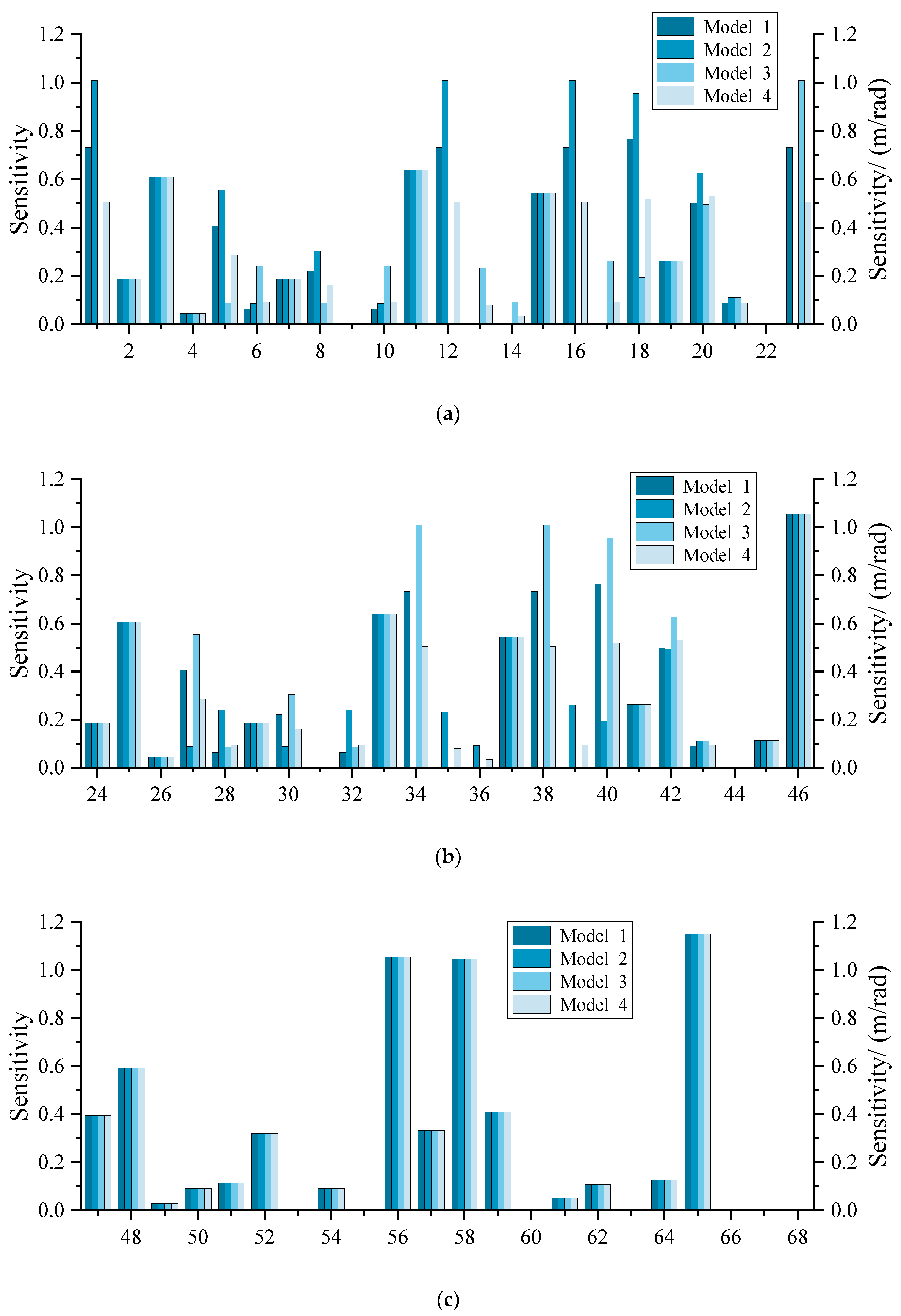
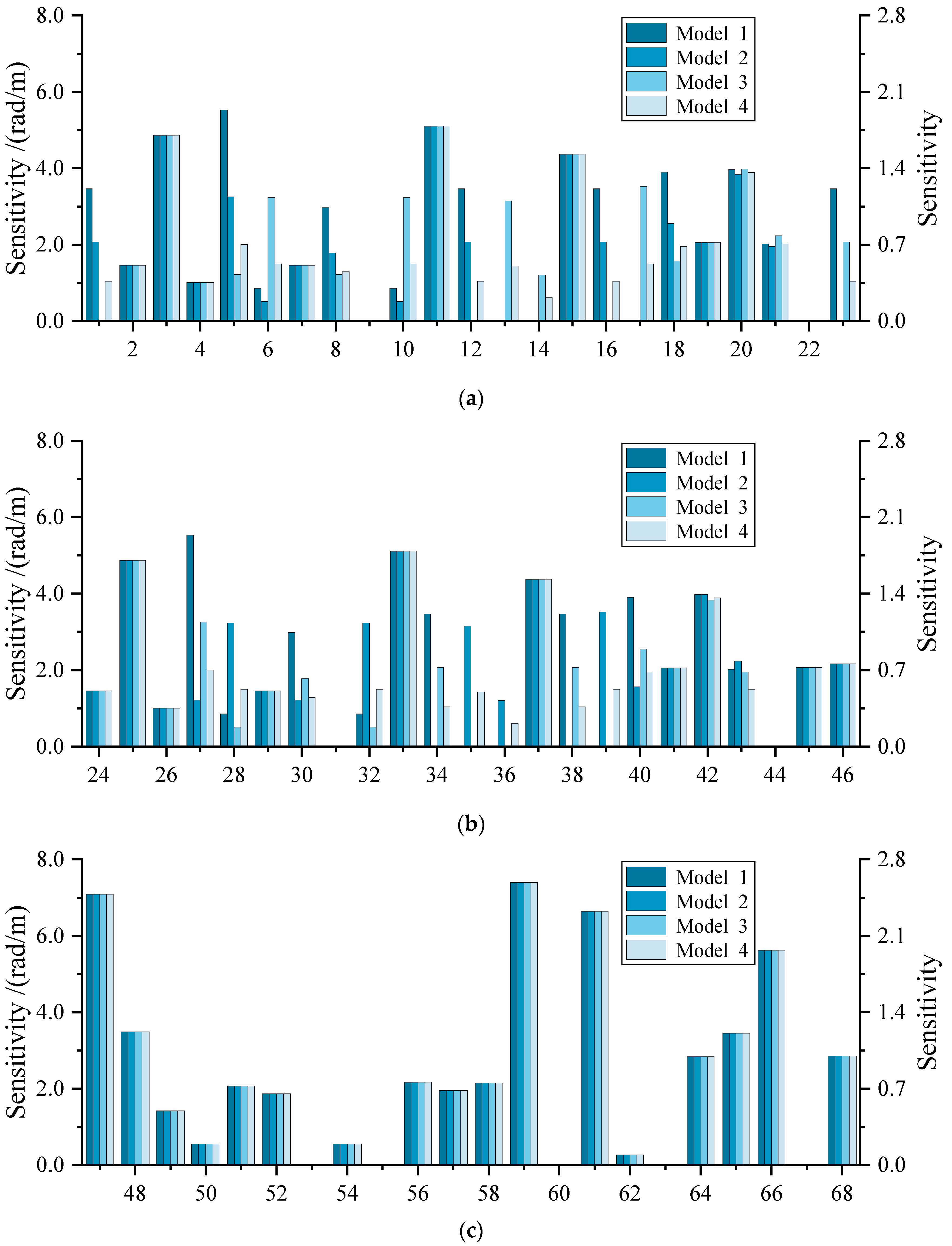
2.4. Comparative Sensitivity Analysis
To evaluate the effectiveness of the proposed four types of geometric error models comparatively, a set of sensitivity indices is formulated through the error coefficient matrix of the spindle head. Herein, for the nth geometric source error, the sensitivity coefficients of the terminal position error and orientation error are defined as follows:
where denotes the element at the ith row and the nth column of the error coefficient matrix .
With the above-defined sensitivity coefficients, the volumetric sensitivity indices of the terminal position error and orientation error aroused from the nth geometric source error throughout the spindle head’s workspace can be formulated as follows:
where V denotes the spindle head’s reachable workspace, which can be identified through a “sliced partition” searching algorithm proposed in our previous publication.
By adopting the above volumetric sensitivity indices, the sensitivities of a total of 68 geometric source errors regarding the terminal position error and orientation error of the spindle head can be computed, as demonstrated in Figure 4 and Figure 5. To facilitate expression, each depicted figure employs two vertical axes with different physical units to accommodate the dimensional differences between sensitivity indicators of the position source errors and orientation source errors.
Figure 4.
Sensitivity indices of geometric source errors regarding terminal position error: (a) sensitivity indices of the 1st to 23rd source errors; (b) sensitivity indices of the 24th to 46th source errors; (c) sensitivity indices of the 47th to 68th source errors.
Figure 5.
Sensitivity indices of geometric source errors regarding terminal orientation error: (a) sensitivity indices of the 1st to 23rd source errors; (b) sensitivity indices of the 24th to 46th source errors; (c) sensitivity indices of the 47th to 68th source errors.
As shown in Figure 4 and Figure 5, different geometric source errors often exhibit varying sensitivities, with some showing zero sensitivity indices. This phenomenon demonstrates that different source errors of the spindle head have varying impacts on its terminal position error and orientation error, and some geometric source errors do not propagate kinematic error effects to the moving platform (such source errors can be disregarded during tolerance design to enhance efficiency). A comparison between Figure 4 and Figure 5 reveals that sensitivity indices for source errors , , , etc., calculated using the proposed four geometric error models, are consistent. This suggests that these models adequately reflect the sensitivity indices of geometric source errors regarding terminal position/orientation error to a certain extent. However, for source errors , , , etc., there are differences in sensitivity values obtained from the geometric error models of model 1, model 2, model 3, and model 4, as shown in Table 4.
Table 4.
Identifiability of the source errors in different geometric error models.
From Table 4, it can be observed that model 1 fails to identify sensitivity indices for source errors , , , etc.; model 2 fails for source errors , , , etc.; and model 3 fails for source errors , , , etc. Meanwhile, model 4 successfully identifies sensitivity indices for all geometric source errors of the spindle head. This indicates that model 4 can effectively reflect the influence of geometric source errors on the terminal position/orientation error of the spindle head, thereby providing more rational guidance for source error identification. As a result, the geometric model considering all constraint wrenches of limb structures can be adopted as the basis of the error propagation intensity analysis and the tolerance design of such over-constrained mechanical systems.
The summary of this chapter is as follows: Several error models are established, and the optimal model is selected by comparing their different sensitivity coefficients. First, the structure and dimension parameters are described, and the relevant values of dimension parameters are determined based on existing research. Subsequently, error models of the limbs are established, and the passive joint errors are eliminated by taking the inner product with a driven wrench and constraint wrench. Finally, they are sorted into the different error models of the parallel mechanism, and the optimal error model is selected by comparing the sensitivity coefficients.
3. Error Propagation Analysis with Kinematic Interactions
In this section, a set of error propagation indices and coupled error propagation indices is proposed to analyze the error propagation at the limb structural level and the mechanical system level, respectively, revealing the influence pattern of the kinematic interactions between the limbs on the terminal accuracy of the over-constrained spindle head.
3.1. Error Propagation Index
Based on the geometric error modeling, a set of error propagation indices is proposed to describe the perturbation effects of the geometric source errors on the position and the orientation of the individual limb structure quantitatively, which is formulated as follows:
where represents the jth row of the error twist of the ith limb measured in the frame ; and and denote the linear error propagation index and the angular error propagation index of the ith individual limb structure, respectively.
From the above definitions, it can be found that the error propagation index quantitatively describes how much the perturbation of geometric errors affect the kinematic accuracy of the individual limb structure (without the kinematic interactions among limb structures). In such a way, a larger value of the error propagation index means a “stronger” geometric error propagation ability, indicating that more attention should be paid to the corresponding design tolerance when designing such a limb structure of the spindle head.
Considering the kinematic interactions among limb structures of the over-constrained spindle head, one may define the coupled error propagation index for the ith limb in the spindle head as follows:
where represents the jth row and the ith column of the error twist of the platform of the spindle head in which source errors only adopted in the ith limb; and and denote the coupled linear error propagation index and the coupled angular error propagation index of the ith individual limb structure in the over-constrained spindle head, respectively.
From the above Equation (18), it is evident that the coupled error propagation index quantitatively describes the perturbation to the terminal accuracy of the spindle head caused by the geometric errors of an individual limb structure (with the kinematic interactions among limb structures). In other words, a larger coupled error propagation index indicates a greater influence of the corresponding limb on the terminal accuracy of the spindle head, necessitating more attention during tolerance design and structural optimization stages.
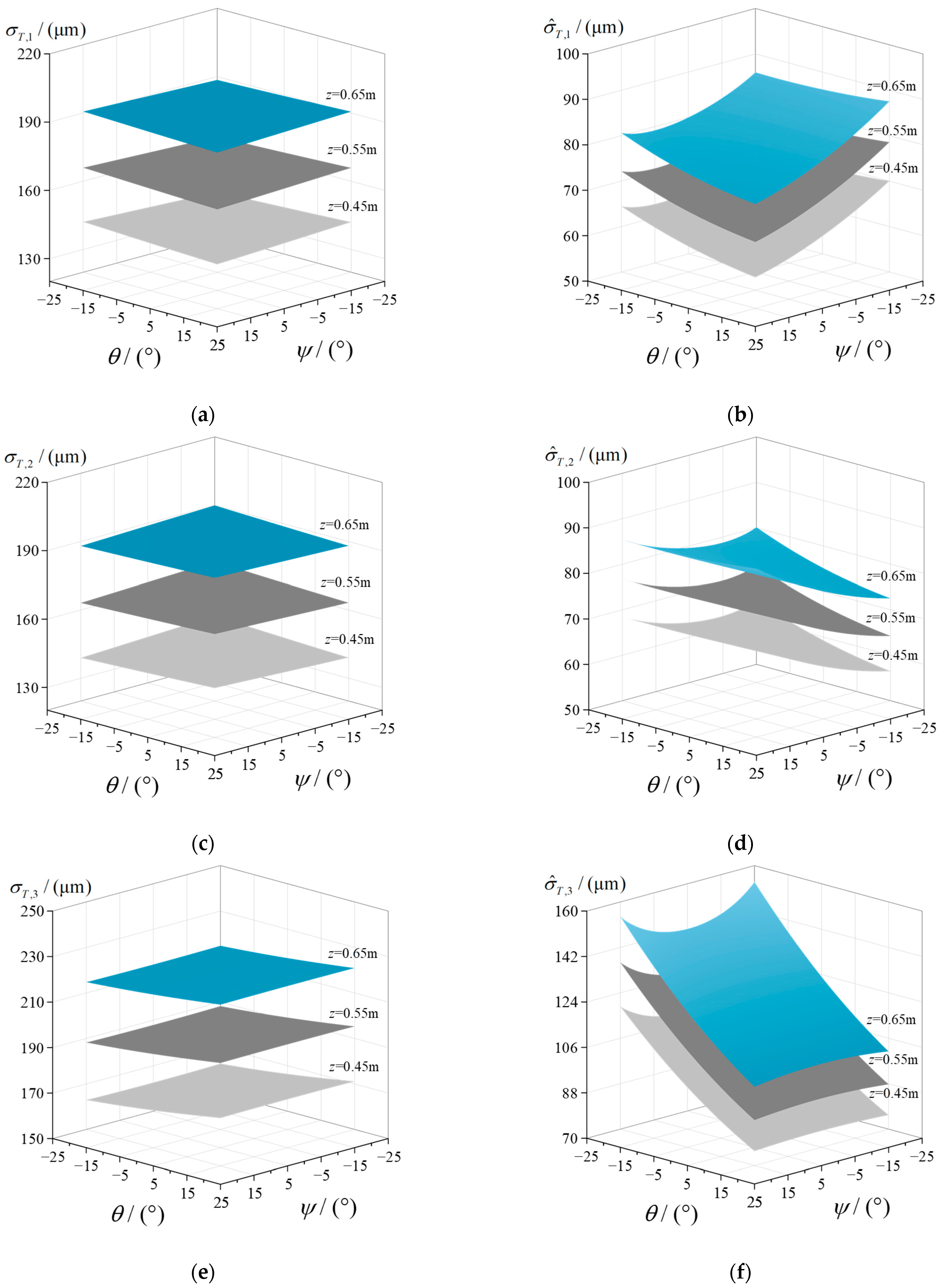
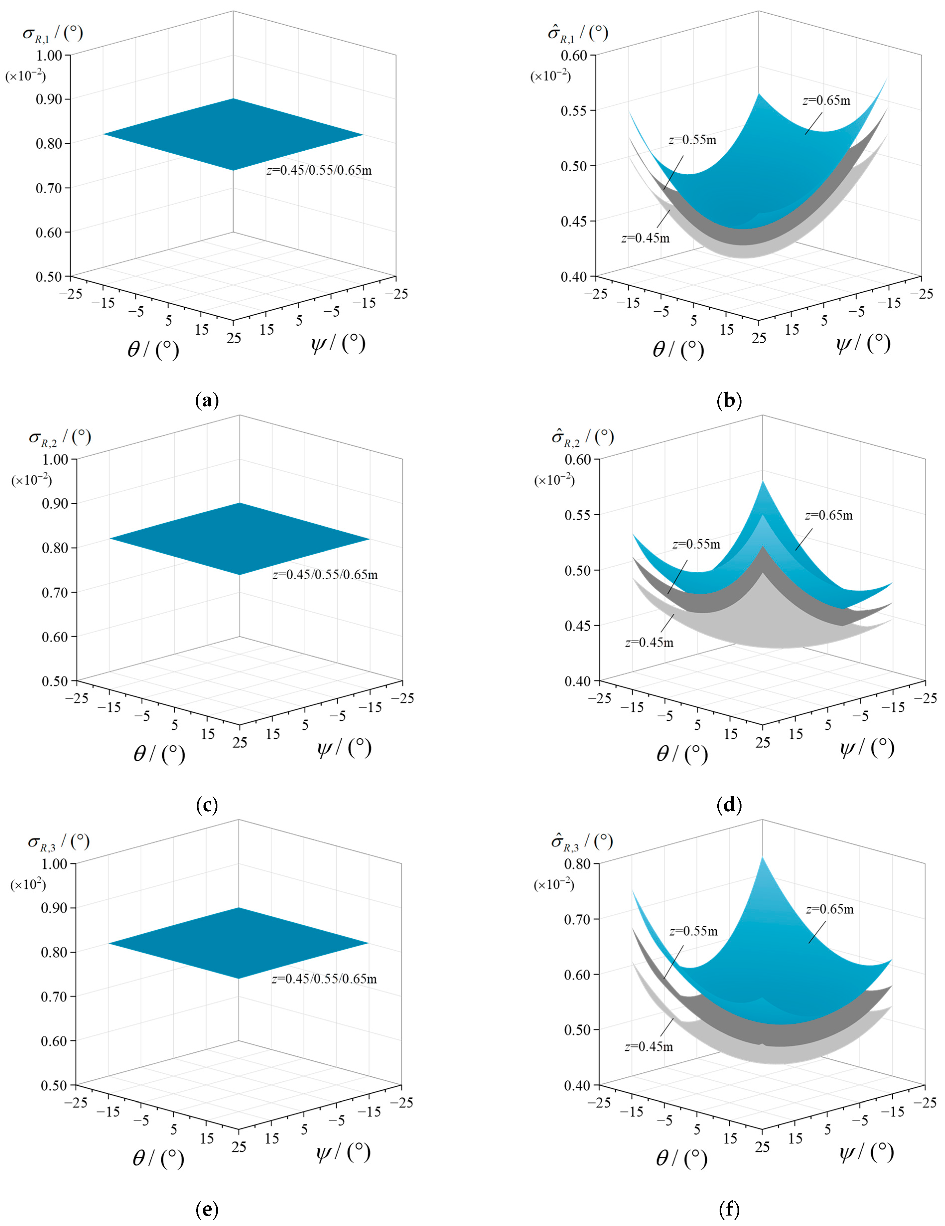
3.2. Error Propagation Analysis for Individual Limb
Without the loss of generality, the initial tolerances of the limb assemblages of the spindle head are given in Table 5, Table 6 and Table 7 based on engineering experience. For batch production of the components in the spindle head, the geometric source errors are random variables which are characterized by normal distributions. The value of a position or orientation source error can be generated from a normal distribution with a mean value of zero and a standard deviation of 1/6 corresponding tolerances, listed in Table 5, Table 6 and Table 7. Thereafter, Monte Carlo simulations of the geometric errors of the spindle head are carried out in the allowed tolerance zones. The variations of the linear/angular error propagation index and the coupled linear/angular error propagation index for three limb structures of the spindle head are illustrated in Figure 6 and Figure 7, respectively. The number of samples is set as 105.
Table 5.
Tolerances of the PRU limbs (i = 1,2).
Table 6.
Tolerances of the PRS limbs.
Table 7.
Tolerances of the error of joint motion.
Figure 6.
Variations of the linear error propagation index and the coupled linear error propagation index for the three limb structures: (a) linear error propagation index of limb 1; (b) coupled linear error propagation index of limb 1; (c) linear error propagation index of limb 2; (d) coupled linear error propagation index of limb 2; (e) linear error propagation index of limb 3; (f) coupled linear error propagation index of limb 3.
Figure 7.
Variations of the angular error propagation index and the coupled angular error propagation index for the three limb structures: (a) angular error propagation index of limb 1; (b) coupled angular error propagation index of limb 1; (c) angular error propagation index of limb 2; (d) coupled angular error propagation index of limb 2; (e) angular error propagation index of limb 3; (f) coupled angular error propagation index of limb 3.
Figure 6a,c,e shows the variations of the linear error propagation index of the three limb structures. It can be seen that the linear error propagation indices of all three limbs increase with the increase in the position coordinate z and are less impacted by the orientation coordinates ψ and θ of the spindle head’s platform. Figure 6b,d,f shows the variations of the coupled linear error propagation index of the three limb structures. It is obvious that the coupled linear error propagation indices of the three limbs are mainly impacted by the orientation coordinates ψ and θ, rather than the coordinate z.
Furthermore, in Figure 6, the coupled linear error distributions of limb 1 and limb 2 are mirrored with respect to the plane of ψ = 0, and the coupled linear error distribution of limb 3 is symmetric with respect to the plane of ψ = 0. The observed phenomena indicate that regardless of whether kinematic interactions among limb structures are considered, the linear error propagation index and the coupled linear error propagation index for the three limbs are pose-dependent. For instance, limb 1 has a greater impact on the terminal linear error at larger absolute values of the orientation coordinate ψ, while limb 3 has a more significant influence at larger absolute values of orientation coordinate θ. Therefore, incorporating the error propagation performance at different configurations into the trajectory planning process of the spindle head can help enhance its terminal accuracy.
Figure 7a,c,e show the variations of the angular error propagation index of the three limb structures. It can be seen that the position and orientation coordinates z, ψ, and θ do not affect the angular error propagation indices of the three limbs. Figure 7b,d,f show the variations of the coupled angular error propagation index of three limb structures. It can be seen that the coupled angular error propagation indices of three limbs increase with the increasing of the position coordinate z, while the orientation coordinates ψ and θ have different effects on these indices and have more significant influence than the coordinate z. Similar to the linear error distributions described in Figure 6, the coupled angular error distributions of limb 1 and limb 2 are mirrored with respect to the plane of ψ = 0, and the coupled angular error distribution of limb 3 is symmetric with respect to the plane of ψ = 0. As a result, the angular error propagation index and the coupled angular error propagation index for the three limbs are pose-dependent too. From the perspective of kinematic enhancement, the over-constrained spindle head has better terminal accuracy when the orientation is near the home position with ψ = 0 and θ = 0.
With the error propagation effects of limbs in mind, the relative deviations of / and / (i = 1, 2, 3) are employed to describe quantitatively the extent to which the geometric errors of the ith limb structure is affected by the kinematic interactions of the other limbs, as expressed in the following:
In Equation (19), and represent the relative changes in the linear and angular errors of the ith limb before and after considering the kinematic interactions of the limb structures, respectively, which measure the magnitude of the kinematic error coupling at the limb structural level. Both and are positive values, indicating that the ith limb is experiencing error compensation due to the kinematic interactions of the other limbs, and vice versa. Moreover, the larger the values of and , the more pronounced the compensatory effect of the other limb structures on the ith limb. For clarity, the average and maximum values of and within the spindle’s workspace are presented in Table 8.
Table 8.
Linear/angular error of the ith limb before and after considering the kinematic interactions of other limbs.
Table 8 shows that both the average and maximum values of and are positive, with and and and being equal, respectively. This observation suggests that the linear and angular errors of the ith limb structure are subject to varying degrees of compensation from the other limbs. Additionally, due to the identical structure and symmetrical arrangement of limb 1 and limb 2, their compensatory effects from the other limbs are also consistent. Furthermore, the comparison reveals that / and / are both greater than and , indicating that the geometric error compensation experienced by limb 1 and limb 2 is greater than that experienced by limb 3. Therefore, it is necessary to pay closer attention to the structural design and component selection of limb 3 during the design phase to ensure that it possesses equivalent motion accuracy to the other limbs, thus not compromising the overall motion performance of the over-constrained spindle head.
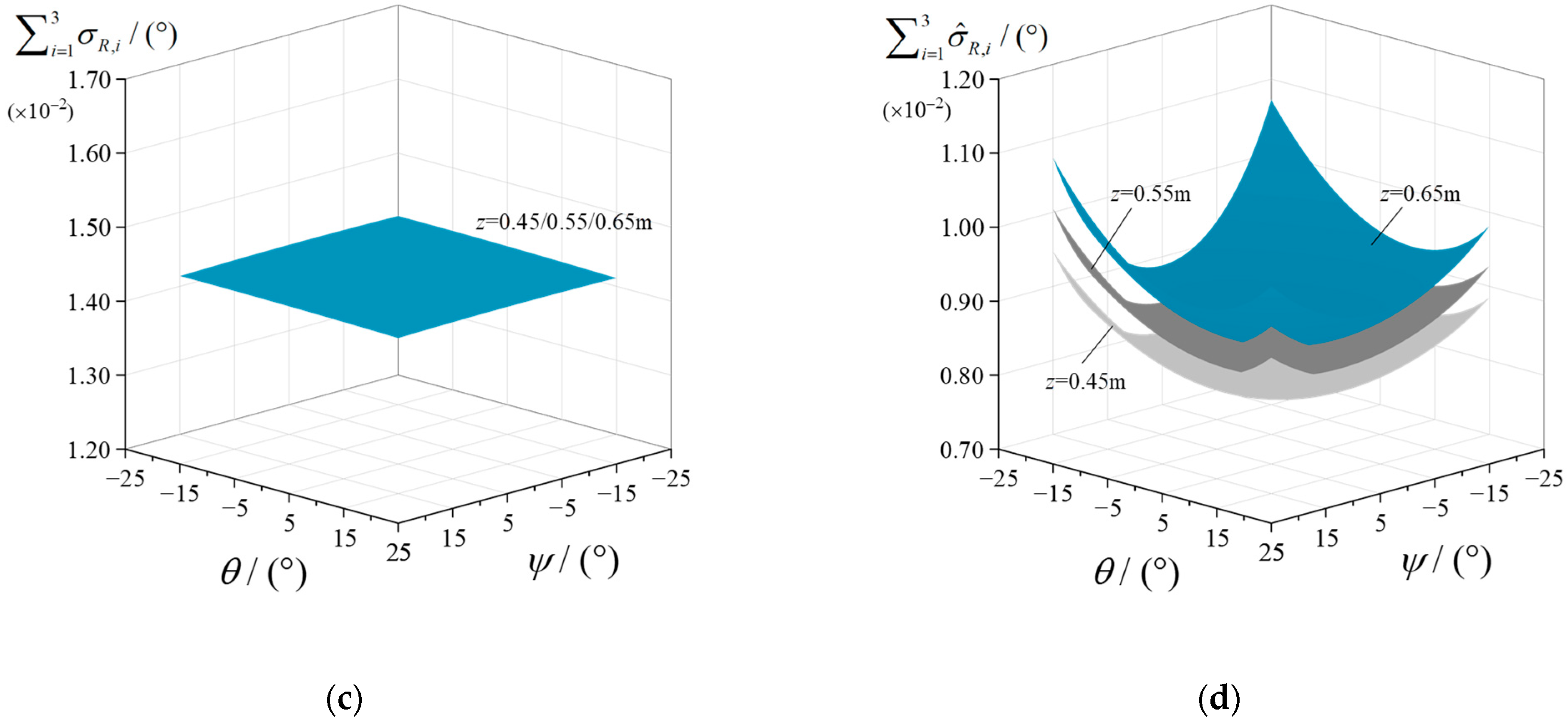
3.3. Error Propagation Analysis for Terminal Platform
The terminal error of the spindle head stems from the cumulative effects of the kinematic errors of the three limb structures. Consequently, / and / can represent the terminal linear/angular errors of the spindle head without and with considering the kinematic interactions of the three limbs, respectively, as depicted in Figure 8.

Figure 8.
Cumulative effects on terminal errors of the spindle head with or without the kinematic interactions of the three limbs: (a) terminal linear error without the kinematic interactions of the three limbs; (b) terminal linear error with the kinematic interactions of the three limbs; (c) terminal angular error without the kinematic interactions of the three limbs; (d) terminal angular error with the kinematic interactions of the three limbs.
Figure 8a,c illustrate the distributions of linear and angular errors at the spindle head’s terminal, respectively, when the kinematic interactions of the three limbs are not considered. It is evident from the figures that the terminal linear error is significantly influenced by the position coordinate z, while the angular error is unaffected by both z and the orientation coordinates ψ and θ. In contrast, Figure 8b,d show the distributions of linear and angular errors at the spindle head’s terminal when the kinematic interactions of the three limbs are taken into account. Both linear error and angular error at the spindle head’s terminal are significantly influenced by both the position coordinate z and the orientation coordinates ψ and θ, demonstrating clear position dependence. To reflect the impact of the kinematic interactions of limbs on the terminal accuracy of the spindle head intuitively, it is convenient to take the relative deviations of / and /, as expressed in the following:
In Equation (20), and denote the relative changes in the terminal linear error and the terminal angular error of the spindle head before and after considering the kinematic interactions of limbs, respectively, which quantify the magnitude of the kinematic error coupling at the level of mechanical system. Both and being positive indicates mutual compensation between the limb structures, whereas negative values suggest otherwise. Furthermore, the greater the values of and , the more pronounced the mutual compensation between the limb structures. For clarity, the average and maximum of and within the spindle head’s reachable workspace are provided in Table 9.
Table 9.
Terminal error of the spindle head before and after considering the kinematic interactions of limbs.
Table 9 reveals that both the average and maximum values of and are positive, with the average value of reaching up to 47.7%. This phenomenon once again indicates that there is a mutual compensation relationship between the geometric errors of the limbs in such an over-constrained spindle head, and such interactive compensation significantly reduces the moving platform’s linear error, enhancing the terminal accuracy of the spindle head.
4. Conclusions
- (1)
- Four geometric error models considering different combinations of constraint wrenches are established for the over-constrained spindle head. A set of sensitivity indices is formulated to evaluate the effectiveness of these models. Comparative sensitivity analysis suggests that among the three error models considered without all constraints, there are six source errors that cannot be identified. A model incorporating all constraint wrenches can effectively reflect the influence of all geometric source errors on the terminal position/orientation error of the spindle head and is suitable for error propagation intensity analysis of such an over-constrained mechanical system.
- (2)
- The proposed error propagation indices quantitatively describe how much the perturbation of geometric errors affect the kinematic accuracy of the individual limb structure. The coupled error propagation indices quantitatively describe the perturbation to the terminal accuracy of the spindle head caused by the geometric errors of an individual limb structure. These two kinds of performance indices can be adopted to analyze the error propagation at the limb structural level and the mechanical system level of the spindle head, respectively.
- (3)
- Further error propagation analysis results show that the error propagation indices for the three limbs are pose-dependent, and the kinematic errors of a limb structure are subject to varying degrees of compensation from the other limbs. The average of linear error indices of limb 1 and limb 2 are reduced by 56.6%; the average of linear error indices of limb 3 are reduced by 43.2%. Moreover, there is a mutual compensation relationship between the geometric errors of the limbs in such an over-constrained spindle head. By taking the mixing mechanism as an example, the results show that the average linear error is reduced by 47.7%. Such interactive compensation significantly reduces the moving platform’s linear error, enhancing the terminal accuracy of the spindle head.
Author Contributions
Conceptualization, T.T.; methodology, Y.S. and H.F.; software, Y.S.; writing—original draft preparation, Y.S.; writing—review and editing, T.T. and H.F.; supervision, T.T. All authors have read and agreed to the published version of the manuscript.
Funding
This work was funded by the Open Research Fund of State Key Laboratory of Intelligent Manufacturing Equipment and Technology (no. IMETKF2024017) and the Science Foundation of Zhejiang Sci-Tech University (ZSTU) (no. 22242255-Y). This work is also funded by the Scientific Research Fund of Zhejiang Provincial Education Department (no. Y202353493).
Data Availability Statement
Data are contained within the article.
Conflicts of Interest
The authors declare no conflicts of interest.
References
- Rong, Y.; Zhang, X.; Dou, T.; Wang, H. Type synthesis of non-overconstrained and overconstrained two rotation and three translation (2R3T) parallel mechanisms with three branched chains. Mech. Sci. 2023, 14, 567–577. [Google Scholar] [CrossRef]
- Righettini, P.; Strada, R.; Cortinovis, F.; Tabaldi, F.; Santinelli, J.; Ginammi, A. An Experimental Investigation of the Dynamic Performances of a High Speed 4-DOF 5R Parallel Robot Using Inverse Dynamics Control. Robotics 2024, 13, 54. [Google Scholar] [CrossRef]
- Görgülü, I.; Dede, M.I.C.; Kiper, G. Stiffness modeling of a 2-DoF over-constrained planar parallel mechanism. Mech. Mach. Theory 2023, 185, 105343. [Google Scholar] [CrossRef]
- Chen, M.; Zhang, Q.; Ge, Y.; Qin, X.; Sun, Y. Dynamic analysis of an over-constrained parallel mechanism with the principle of virtual work. Math. Comput. Model. Dyn. Syst. 2021, 27, 347–372. [Google Scholar] [CrossRef]
- Wang, Y.; Belzile, B.; Angles, J.; Li, Q. Kinematic analysis and optimum design of a novel 2PUR-2RPU parallel robot. Mech. Mach. Theory 2019, 139, 407–423. [Google Scholar] [CrossRef]
- Shen, X.; Xu, L.; Li, Q. Motion/Force constraint indices of redundantly actuated parallel manipulators with over constraints. Mech. Mach. Theory 2021, 165, 104427. [Google Scholar] [CrossRef]
- López-Custodio, P.C.; Dai, J.; Fu, R. Kinematics and constraints of the Exechon robot accounting offsets due to errors in the base joint axes. J. Mech. Robot. 2020, 12, 21109. [Google Scholar] [CrossRef]
- Zhang, J.; Zhao, Y.; Jin, Y. Kinetostatic-model-based stiffness analysis of Exechon PKM. Robot. Comput. Integr. Manuf. 2016, 37, 208–220. [Google Scholar] [CrossRef]
- Zoppi, M.; Zlatanov, D.; Molfino, R. Kinematics analysis of the Exechon tripod. In Proceedings of the ASME 2010 International Design Engineering Technical Conferences and Computers and Information in Engineering Conference, Montreal, QC, Canada, 15–18 August 2010. [Google Scholar] [CrossRef]
- Jin, Y.; Bi, Z.M.; Liu, H.T.; Higgins, C.; Price, M.; Chen, W.H.; Huang, T. Kinematic analysis and dimensional synthesis of Exechon parallel kinematic machine for large volume machining. J. Mech. Robot. 2015, 7, 041004. [Google Scholar] [CrossRef]
- Yuan, Y.; Sun, W. An integrated kinematic calibration and dynamic identification method with only static measurements for serial robot. IEEE/ASME Trans. Mechatron. 2023, 28, 2762–2773. [Google Scholar] [CrossRef]
- Shukla, G.; Whitney, D.E. The path method for analyzing mobility and constraint of mechanisms and assemblies. IEEE Trans. Autom. Sci. Eng. 2005, 2, 184–192. [Google Scholar] [CrossRef]
- Raksiri, C.; Pa-im, K.; Rodkwan, S. An Analysis of Joint Assembly Geometric Errors Affecting End-Effector for Six-Axis Robots. Robotics 2020, 9, 27. [Google Scholar] [CrossRef]
- Kong, L.Y.; Chen, G.L.; Wang, H.; Huang, G.; Zhang, D. Kinematic calibration of a 3-PRRU parallel manipulator based on the complete, minimal and continuous error model. Robot. Comput. Integr. Manuf. 2021, 71, 102158. [Google Scholar] [CrossRef]
- Fu, Z.; Dai, J.; Yang, K.; Chen, X.; López-Custodio, P. Analysis of unified error model and simulated parameters calibration for robotic machining based on lie theory. Comput. Integr. Manuf. 2020, 61, 101855. [Google Scholar] [CrossRef]
- Sun, T.; Liu, C.; Lian, B.; Wang, P.; Song, Y. Calibration for precision kinematic control of an articulated serial robot. IEEE Trans. Ind. Electron. 2021, 68, 6000–6009. [Google Scholar] [CrossRef]
- Sun, T.; Lian, B.; Yang, S.; Song, Y. Kinematic calibration of serial and parallel robots based on finite and instantaneous screw theory. IEEE Trans. Robot. 2020, 36, 816–834. [Google Scholar] [CrossRef]
- Zhao, A.; Toudeshki, A.; Ehsani, R.; Sun, J.-Q. Data-Driven Inverse Kinematics Approximation of a Delta Robot with Stepper Motors. Robotics 2023, 12, 135. [Google Scholar] [CrossRef]
- Ni, Y.; Cui, Y.; Jia, S.; Lu, C.; Lu, W. Error identification and compensation of 1T2R parallel power head based on trajectory optimization and principal component analysis. IEEE Trans. Robot. 2020, 36, 816–834. [Google Scholar] [CrossRef]
- Luo, X.; Xie, F.; Liu, X.; Xie, Z. Kinematic calibration of a 5-axis parallel machining robot based on dimensionless error mapping matrix. Robot. Comput. Integr. Manuf. 2021, 70, 102115. [Google Scholar] [CrossRef]
- Mei, B.; Xie, F.; Liu, X.; Yang, C. Elasto-geometrical error modeling and compensation of a five-axis parallel machining robot. Precis. Eng. 2021, 69, 48–61. [Google Scholar] [CrossRef]
- Chen, G.; Kong, L.; Li, Q.; Wang, H.; Lin, Z. Complete, minimal and continuous error models for the kinematic calibration of parallel manipulators based on POE formula. Mech. Mach. Theory 2018, 121, 844–856. [Google Scholar] [CrossRef]
- Ye, H.; Wu, J.; Wang, D. A general approach for geometric error modeling of over-constrained hybrid robot. Mech. Mach. Theory 2022, 176, 104998. [Google Scholar] [CrossRef]
- Jiang, S.; Chi, C.; Fang, H.; Tang, T.; Zhang, J. A minimal-error-model based two-step kinematic calibration methodology for redundantly actuated parallel manipulators: An application to a 3-DOF spindle head. Mech. Mach. Theory 2022, 167, 104532. [Google Scholar] [CrossRef]
- Luo, X.; Xie, F.; Liu, X. Kinematic calibration of the 3-degree-of-freedom redundantly actuated spatial parallel module of a five-axis hybrid machine. Proc. Inst. Mech. Eng. Part B J. Eng. Manuf. 2020, 234, 1185–1197. [Google Scholar] [CrossRef]
- Shen, Y.; Chen, M.; Skelton, R.E. A Markov data-based approach to system identification and output error covariance analysis for tensegrity structures. Nonlinear Dyn. 2024, 112, 7215–7231. [Google Scholar] [CrossRef]
- Ye, C.; Yang, J.; Zhao, H.; Ding, H. Task-dependent workpiece placement optimization for minimizing contour errors induced by the low posture-dependent stiffness of robotic milling. Int. J. Mech. Sci. 2021, 205, 106601. [Google Scholar] [CrossRef]
- Chen, C.; Peng, F.; Yan, R.; Li, Y.; Wei, D.; Fan, Z. Stiffness performance index based posture and feed orientation optimization in robotic milling process. Robot. Comput. Integr. Manuf. 2019, 55, 29–40. [Google Scholar] [CrossRef]
- Wang, L.; Li, M.; Yu, G. A Novel Error Sensitivity Analysis Method for a Parallel Spindle Head. Robotics 2023, 12, 129. [Google Scholar] [CrossRef]
- Luo, X.; Xie, F.; Liu, X. Error modeling and sensitivity analysis of a novel 5-degree of freedom parallel kinematic machine tool. Proc. Inst. Mech. Eng. Part B J. Eng. Manuf. 2019, 233, 1637–1652. [Google Scholar] [CrossRef]
- Wu, M.; Yue, X.; Chen, W.; Nie, Q.; Zhang, Y. Accuracy analysis and synthesis of asymmetric parallel mechanism based on Sobol-QMC. Proc. Inst. Mech. Eng. Part C J. Mech. Eng. Sci. 2020, 234, 4200–4214. [Google Scholar] [CrossRef]
- Li, G.; Qu, H.; Guo, S. Sensitivity analysis of a planar parallel manipulator with kinematic redundancy. J. Mech. Eng. 2020, 56, 45–57. [Google Scholar] [CrossRef]
- Shi, K.; Wang, Z.; Yan, C.; Wang, Z. Design and performance analysis of the 4UPS-RRR parallel ankle rehabilitation mechanism. Mech. Sci. 2024, 15, 417–430. [Google Scholar] [CrossRef]
- Wang, J.; Lau, H.Y.K. Dexterity Analysis Based on Jacobian and Performance Optimization for Multi-Segment Continuum Robots. ASME J. Mech. Robot. 2021, 13, 061012. [Google Scholar] [CrossRef]
- Nabavi, S.N.; Shariatee, M.; Enferadi, J.; Akbarzadeh, A. Parametric design and multi-objective optimization of a general 6-PUS parallel manipulator. Mech. Mach. Theory 2020, 152, 103913. [Google Scholar] [CrossRef]
Disclaimer/Publisher’s Note: The statements, opinions and data contained in all publications are solely those of the individual author(s) and contributor(s) and not of MDPI and/or the editor(s). MDPI and/or the editor(s) disclaim responsibility for any injury to people or property resulting from any ideas, methods, instructions or products referred to in the content. |
© 2024 by the authors. Licensee MDPI, Basel, Switzerland. This article is an open access article distributed under the terms and conditions of the Creative Commons Attribution (CC BY) license (https://creativecommons.org/licenses/by/4.0/).