Abstract
The multiway valve is the core control element of the hydraulic system in construction machinery, such as excavators. Its complex internal structure, especially the flow channels, significantly impacts the machine’s efficiency and reliability. This study focuses on the boom flow channel of excavator multiway valves and establishes a multi-physical field coupling simulation model. We propose six key flow channel structural parameters and analyze changes in the valve’s flow field, temperature field, and structural field using orthogonal test simulation data. The range analysis method identifies the primary and secondary influences of structural parameters on pressure loss, temperature, stress, and strain. A multi-objective optimization model was developed using a neural network and the Non-dominated Sorting Genetic Algorithm II(NSGA-II), with pressure loss and maximum stress as the optimization objectives. The Pareto front solution set for key flow channel parameters was calculated. The optimization results showed a 9.0% reduction in pressure loss and a 40.7% reduction in maximum stress. A test bench verified the simulation model, achieving prediction accuracies of 94.8% for pressure loss in the inlet area and 92.3% in the return area. This method can provide a reference for the optimal design of the dynamic characteristics of high-pressure multiway valves.
1. Introduction
Multiway valves are the core control components of hydraulic systems in engineering machinery, such as excavators. They integrate multiple directional control valves, along with auxiliary valves with different functions, to meet the control requirements for individual and combined actions of multiple actuators. With the trend towards higher pressure and speed in engineering machinery, the inefficiencies of multiway valves have become increasingly apparent. The structural parameters of the internal flow channels are crucial factors affecting their performance. Undetected design flaws can lead to increased pressure losses [1], resulting in higher energy consumption and reduced operational efficiency. Moreover, inconsistent fluid velocities within the multiway valves result in uneven temperature distribution, causing high-temperature fluid to transfer heat to the valve structure and compromising its reliability due to thermal stress [2]. Therefore, analyzing the complex flow field characteristics of internal channels in multiway valves and considering the coupling effects of flow, temperature, and structural fields is crucial for enhancing their overall performance.
In recent years, with significant improvements in computer processing power and the maturation of general fluid simulation software, the accessibility of Computational Fluid Dynamics (CFD) technology has greatly increased. Scholars both domestically and internationally have utilized CFD technology to investigate diverse aspects of hydraulic valve performance, including the analysis of pressure losses within valve internals and the optimization of flow channels [3,4]. For instance, Simic and Herakovic adjusted the geometry parameters of the sliding-spool and seat valve to reduce axial hydraulic forces and enhance overall hydraulic valve performance [5,6]. Wu analyzed the pressure field, velocity field, and turbulence energy field of excavator speed switching valve channels and ports, leading to structural improvements that effectively reduced static pressure losses and turbulence energy losses within the valve [7]. Qin optimized valve port designs, significantly lowering pressure losses, turbulence intensity, maximum exit velocities, and velocity non-uniformity [8].
As advanced equipment continues to evolve, single-field simulations are insufficient for comprehensive structural evaluations, prompting more scholars to explore multi-physical field coupling simulation methods [9,10,11,12]. In addition, the temperature will not only cause the structure of the multiway valve to deform, but will also significantly affect the pressure, viscosity and dynamic bulk elastic modulus of the hydraulic oil, so it is necessary to consider the thermal effect when conducting multi-physical field analysis [13,14]. Li Meng conducted simulation studies on pressure losses and heat transfer losses in multiway valves, revealing the influence of factors such as fluid mass flow rate, inlet temperature, and valve material on valve flow characteristics [15]. Xu Liping investigated leakage and clamping issues in multiway valve bodies and spools of crawler tractor through thermal-fluid-structure coupling simulations [16]. Peng focused on large high-temperature vacuum valves, constructing a thermal-fluid-structure coupling model to understand the distribution of thermal stresses and the influence of three-dimensional dynamics on temperature distribution within the valve [17]. Kazama established a heat-fluid-structure coupling model suitable for an axial piston pump and motor slipper pair, in which three-dimensional energy equations and heat conduction equations were considered [18]. Tan established a thermal-fluid-structure coupling model for wet friction clutches, analyzing their effects on torque and temperature fields [19]. Tang studied near-space airships, developing a thermal-fluid-structure coupling model for the airship envelope layer that accurately reflected stress–strain distributions and deformation patterns [20].
Combining simulation results with optimization algorithms for the optimization of complex structures is now a prevalent trend. These algorithms provide practical solutions for combinatorial optimization problems that traditional optimization techniques struggle to handle [21,22,23,24]. For example, Li utilized genetic algorithms to optimize the structural parameters of multiway valve ports. Comparison through AMESim analysis of the simulation models before and after optimization showed that the optimized spool structure had more stable load characteristics and a wider speed range [25]. Wang proposed a multi-parameter optimization method for the heat dissipation structure of a double-disk magnetic coupler based on orthogonal experimental design. By selecting the minimum temperature of the heat dissipation plate as the objective function, six factors and three-level simulation experiments were designed [26]. Caixeta, in studying the structural and aeroelastic characteristics of flexible aircraft wings, used neural networks to predict the critical flutter speed of the wings and applied genetic algorithms for multi-objective optimization, aiming to maximize the critical flutter speed and minimize the structural mass [27]. Yang employed the response surface methodology (RSM) and genetic algorithms to optimize the port structure of a K-groove multiway valve, improving performance by reducing the pressure drop and the relative deviation of the flow area in the flow field [28]. Duan proposed an optimization approach using an improved backpropagation neural network (BPNN) and the Non-dominated Sorting Genetic Algorithm II (NSGA-II) for optimizing pressure head and efficiency. NSGA-II was used for multi-objective optimization of a micropump, and simulations revealed that the improved model could alleviate the impeller wake and improve pressure distribution and flow direction [29]. For butterfly valve optimization, Sergio Corbera redesigned the butterfly valve based on Pareto-optimal multi-objective genetic algorithms [30]. After determining the parameter variables, design candidates were generated using Design of Experiments (DOE), and the optimal solution was selected through the genetic algorithm. These studies provide valuable references for optimizing the internal flow channels of multiway valves.
Although many scholars have optimized specific structures of multiway valves, research on the multi-physical coupling and optimization of complex internal flow channels is limited. This study addresses issues such as high-pressure loss and high failure rates in multiway valve flow channels by focusing on key design aspects. A multi-physical field coupling simulation model for multiway valves is established to analyze the distribution patterns of flow, temperature, and structural fields. By combining theoretical models, neural networks, and multi-objective optimization algorithms, the internal flow channels are optimized to reduce pressure loss and failure rates. This research provides guidance for reducing internal pressure loss and enhancing the performance of multiway valves, and it lays a foundation for the forward design of the dynamic characteristics of multi-pass valves.
2. Excavator Multiway Valve Model
2.1. Geometric Model
Excavator multiway valves typically consist of two or more directional control valves, integrating various flow, pressure, and directional control functions. These valves are tightly connected through internal flow channels and serve as key control components in the hydraulic systems of excavators, enabling the control of multiple hydraulic actuators [31]. As shown in Figure 1, the middle coupling of a multiway valve from a company includes the boom 1 section, boom 2 section, bucket section, and a spare section. This study focuses on the boom 1 and boom 2 sections within the middle coupling.
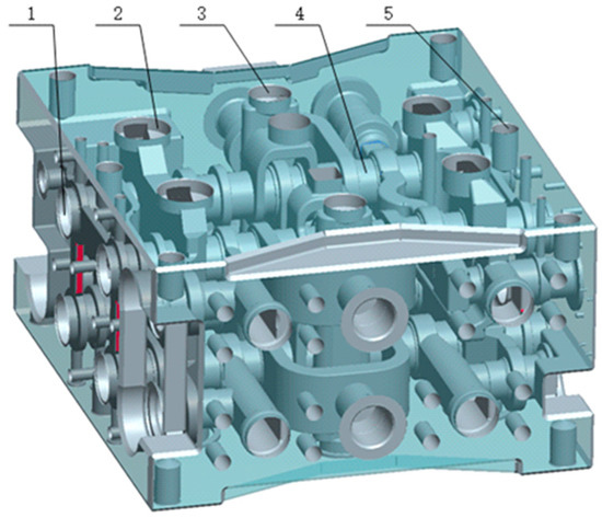
Figure 1.
Schematic diagram of excavator multiway valve boom-connected: 1 spool hole, 2 low pressure inlet, 3 high pressure inlet A, 4 internal flow path, 5 bolt hole.
The hydraulic circuit diagram of the excavator’s multiway valve is shown in Figure 2. The boom 1 and boom 2 circuits of the multiway valve are primarily integrated into the intermediate valve block of the multiway valve, collectively achieving the lifting and lowering actions of the excavator boom.
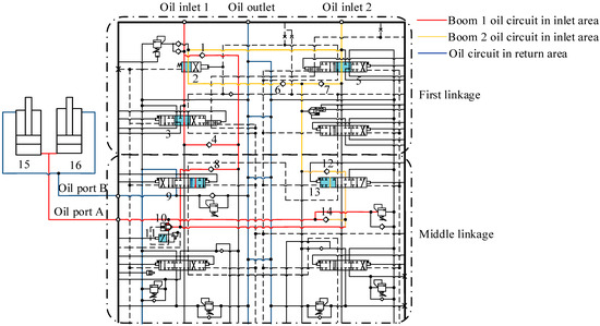
Figure 2.
Working principle of multiway valve boom coupling: 1 straight valve, 2 check valve A, 3 left travel valve, 4 check valve B, 5 right travel valve, 6 check valve C, 7 check valve D, 8 check valve E, 9 boom 1 valve, 10 check valve F, 11 load-holding valve, 12 check valve G, 13 boom 2 valve, 14 check valve H, 15 boom cylinder A, 16 boom cylinder B.
During the boom lifting operation, the left position of the straight valve (tag1) of the multiway valve is activated, the right position of the boom 1 valve (tag9) is activated, and the left position of the boom 2 valve (tag13) is activated. The load-holding valve is actuated by the pilot pressure signal to the left position, connecting the spring chamber pressure of check valve F with the T port pressure. This allows check valve F (tag10) to be pushed open by the incoming oil pressure, while other function valves remain in the neutral position. The oil supply is simultaneously provided by the two inlet ports of the multiway valve.
Oil from inlet port 1 flows through two paths: one path sequentially passes through the straight valve (tag1) of the primary valve block, the left travel valve (tag3), and check valve B (tag4); the other path passes through check valve A (tag2). After converging, the combined flow enters the intermediate valve block, opens check valve E (tag8), and exits through the right position of the boom 1 valve (tag9).
Oil from inlet port 2 also flows through two paths: one path passes through the straight valve (tag1) of the primary valve block, and the other path passes through the right travel valve (tag 5). Each path opens check valves C (tag 6) and D (tag 7), respectively, before converging in the intermediate valve block, where it opens check valve G (tag12) and exits through the left position of the boom 2 valve (tag13). The oil flowing from the follower boom 1 valve (tag9) and the boom 2 valve (tag13) will merge, and the check valve F (tag10) and the check valve H (tag14) will flow out from the working oil port A into the rodless cavity of boom cylinder A(tag15) and boom cylinder B (tag16). The flow diagram of the oil is shown in Figure 3.
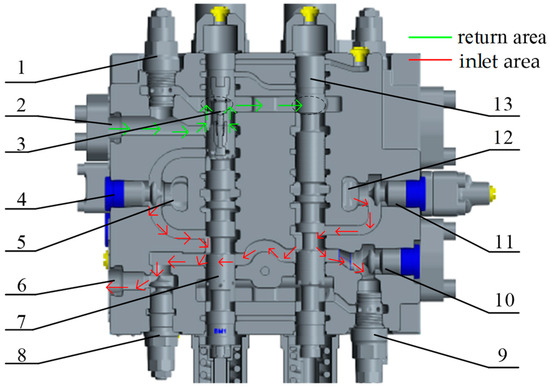
Figure 3.
Schematic diagram of oil flow in boom lift valve: 1 overload fill valve, 2 working port B, 3 return port, 4 check valve E, 5 inlet port 1, 6 working port A, 7 boom X spire, 8 check valve F, 9 overload fill valve, 10 check valve H, 11 check valve G, 12 inlet port 2, 13 boom Y spool.
2.2. Geometric Model and Mesh Model
The spool stroke of the multiway valve is 12 mm in the fully open position. The spool is adjusted to the specified position, and all related check valves are fully opened. Simplifying some model features, the fluid domain models of the oil inlet and outlet regions are generated. The model is meshed using tetrahedral elements, with a global element size of 0 m for the fluid domain. The throttle groove is subjected to mesh refinement with a size of 0.5 mm. The resulting meshes for the oil inlet and outlet regions are approximately 6.79 million and 5.26 million, respectively. The valve body model is also meshed using tetrahedral elements Soild 187 with a global element size of 3 mm, resulting in approximately 1.22 million meshes for the valve body. The meshing of the entire computational domain is shown in Figure 4.
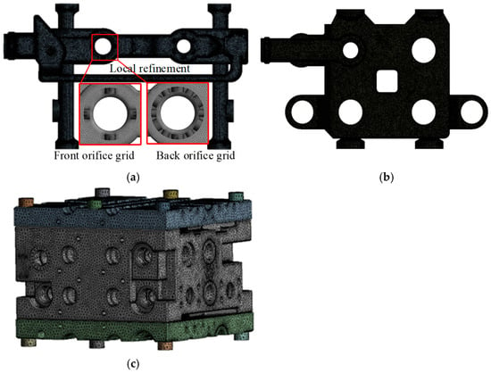
Figure 4.
Schematic diagram of fluid-thermally solid coupling grid division:(a) Model grid of oil inlet area, (b) Return area model grid, (c) Valve body model grid.
2.3. Multi-Physics Field Coupling Simulation Model
Analyzing the performance variations of the multiway valve under the influence of the flow field, temperature field, and structural field reveals that the deformation of the structural field is minimal and has a negligible impact on the flow field and temperature field. Therefore, the influence of the structural field on the flow field and temperature field is disregarded, and a one-way fluid-thermal-structural coupling approach is adopted for the solution. Based on the ANSYS Workbench platform, a one-way multi-physics coupling simulation system is established, with the relationships between the modules illustrated in Figure 5.
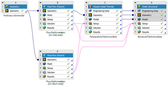
Figure 5.
Unidirectional fluid-thermal-structural coupling simulation system.
- (1)
- Flow field simulation settings
The flow field simulation is conducted under steady-state conditions. The medium used is a single oil, specifically No. 46 anti-wear hydraulic oil, in accordance with actual engineering practice. The properties of the oil are set as follows: density of 900 kg/m3, thermal conductivity of 0.15 W/(m·K), dynamic viscosity of 0.0405 kg/(m·s), and specific heat capacity of 1890 J/(kg·K). The boundary conditions for the inlet and outlet of the oil inlet and outlet regions are set as velocity inlet and pressure outlet. The boundary conditions are summarized in Table 1.

Table 1.
Boundary conditions of oil inlet and oil return areas.
In the calculations, it is necessary to set the convergence criteria for the computational error. The convergence criteria for the energy equation are set to 10-6, while the convergence criteria for all other equations are set to 10-4. The simulation will stop once these convergence conditions are met.
This paper selects the Realizable k-ε model to analyze the internal flow field of the multiway valve flow channel, as shown in Equation (1).
In the equation, k is the turbulent kinetic energy, m2/s2; ε is the turbulent kinetic energy dissipation rate, m2/s3; μτ is the turbulent viscosity coefficient, kg/(m∙s); σk is the turbulent Prandtl number for kinetic energy, σk = 1.0; σε is the turbulent Prandtl number for the dissipation of turbulent kinetic energy, σε = 1.3; C1ε is the empirical turbulence coefficient, C1ε = 1.44; C2ε is the empirical turbulence coefficient, C2ε = 1.9; ϕ is the constant related to wall roughness; and ν is the kinematic viscosity.
- (2)
- Temperature field simulation settings
After completing the flow field simulation, the results are incorporated as part of the boundary conditions for the temperature field. Thermal exchange between other multiway valve components and the valve body is neglected, focusing only on convective heat exchange between the fluid and the valve body, as well as free radiation from the valve body to the environment. The valve body of the multiway valve is made of corrosion-resistant ductile iron, specifically QT500-7. At a standard temperature of 22 °C, its properties are: density of 7100 kg/m3, Young’s modulus of 1.69 × 10¹¹ Pa, coefficient of linear thermal expansion of 12.5 μm/(K∙m), thermal conductivity of 35.2 W/(m∙°C), and Poisson’s ratio of 0.275. The temperature results from the flow simulations of the inlet and outlet fluid modules are imported into the valve body’s temperature field, as shown in Figure 6. After automatically blending in the temperature field, simulations of the valve body’s temperature field are conducted.
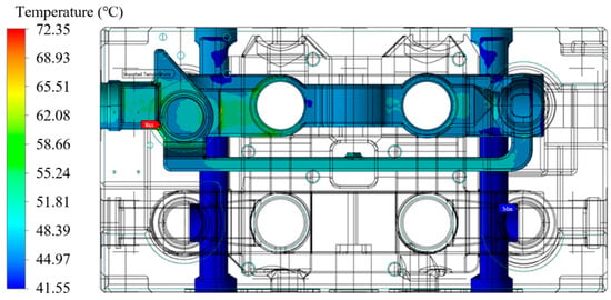
Figure 6.
Temperature distribution contour map of the valve body in contact with the hydraulic oil.
The operating temperature of the multiway valve is generally higher than room temperature, with a default initial temperature, which is the ambient temperature, set at 35 °C. The convective heat transfer between the valve body and the hydraulic oil is treated as a type III boundary condition for heat exchange between a known object surface and its surrounding medium. The convective heat transfer coefficient between the valve body and the hydraulic oil is 1350 W/(m2∙K), while the convective heat transfer coefficient between the valve body and the surrounding air is 100 W/(m2∙K). A steady-state solver is used for the iterative solution.
- (3)
- Structural field simulation settings
The structural field simulation is used to compute the stress and deformation of the multiway valve structure, which are induced by hydraulic pressure and thermal stress. The computed fluid pressure and thermal distribution are imported into the structural field as part of the initial boundary conditions. Through coupled computations, the final results of the structural field are obtained. The imported fluid field results in the structural field are shown in Figure 7, while the imported temperature field results are shown in Figure 8.
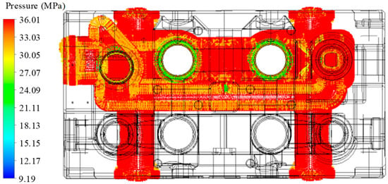
Figure 7.
Flow field pressure in structural field.
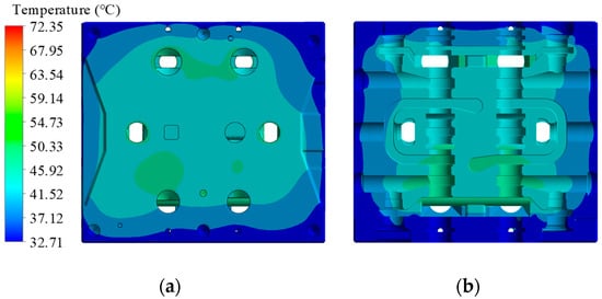
Figure 8.
Temperature distribution in structural field: (a) surface temperature of the valve body, (b) internal temperature of the valve body.
- (4)
- Grid independence verification
The fluid simulation in the oil inlet area and the simulation of the temperature field and structure field of the valve body are taken as the research objects. The pressure loss in the oil inlet area, the maximum temperature of the valve body, the maximum deformation of the valve body and the maximum stress of the valve body are taken as the indexes to evaluate the grid independence. The deviation values of the data in each group are calculated according to the first group of grids, and the results are shown in Table 2 and Table 3.

Table 2.
Grid independence analysis table for the fluid simulation part.

Table 3.
Grid independence analysis for temperature field and structural field simulations.
When the number of mesh elements in the inlet flow field simulation is 6.79 million and the number of mesh elements in the valve body simulation is 1.22 million, the variation in the calculation results is around 1%. This indicates that the flow field simulation mesh meets the independence requirement.
3. Multi-Physics Field Coupling Simulation Result Analysis
After numerical computation convergence, the simulation results of the flow field, temperature field, and structural field are obtained. The contour plot of the flow field is shown in Figure 9. It can be observed that the pressure decreases and the velocity increases as the oil flows through the various valve ports, merging windows, and bends in the flow channels.
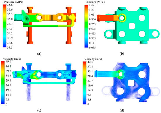
Figure 9.
Flow field simulation results: (a) Pressure distribution contour map of the inlet area flow field, (b) Pressure distribution contour map of the outlet area flow field, (c) Velocity distribution contour map of the inlet area flow field, (d) Velocity distribution in the throttle section of the outlet area.
Due to the throttling effect, the fluid temperature significantly increases as it passes through the throttle slot, while the temperature distribution in other areas remains relatively uniform, as shown in Figure 10.
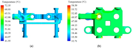
Figure 10.
Temperature distribution contour map of the flow field:(a) Temperature distribution contour map of the inlet area flow field, (b) Temperature distribution contour map of the outlet area flow field.
The temperature in the area near the flow channels is higher than at the valve body’s edges, and the temperature in the intake area is higher than in the return area. The highest temperature in the intake area occurs where the fluid flows from the throttle to the outlet. This is due to the significant increase in fluid velocity caused by throttling at the throttle slot, where viscous shear forces convert some kinetic energy into internal energy, transferring heat to the valve body. Consequently, the temperature at these locations on the valve body is higher. Due to the convective heat dissipation from the valve body to the external environment, the minimum temperature of the valve body is lower than the minimum temperature of the fluid, as shown in Figure 11.
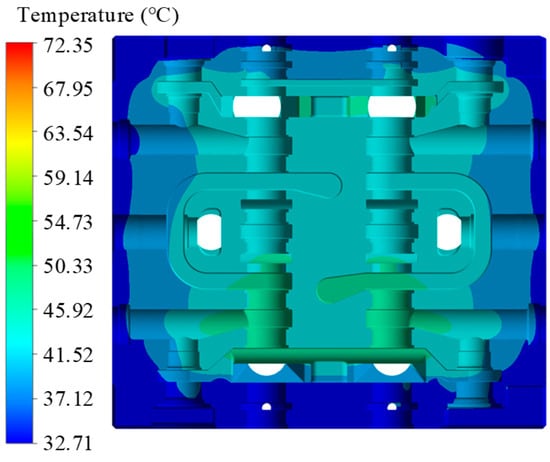
Figure 11.
Temperature distribution contour map of multiway valve flow channel section.
The maximum stress in the structural field appears at the corner of the flow channel in the intake area and can reach 258.17 MPa. The maximum deformation is found near the inlet of the intake flow channel. The deformation direction of the multiway valve is primarily distributed at an angle of 10° to 15° relative to the axial direction of the spool. The radial deformation of the spool is approximately 5.2 μm, while the assembly clearance of the spool is 10 μm. Therefore, the deformation near the spool will not affect the assembly between the spool and the valve body, as shown in Figure 12.

Figure 12.
Multiway valve flow channel cross-sectional stress–strain distribution contour map: (a) Internal surface stress map of the flow channel, (b) Internal deformation of the flow channel.
4. Flow Channel Structural Optimization Design
4.1. Choosing Optimization Parameters
This study selected six key design parameters for the flow channel structure: check valve diameter a, channel width b, channel depth c, fillet diameter d, flow cone width e, and inlet fillet diameter f, as shown in Figure 13. The initial values of these flow channel structural parameters are listed in Table 4.
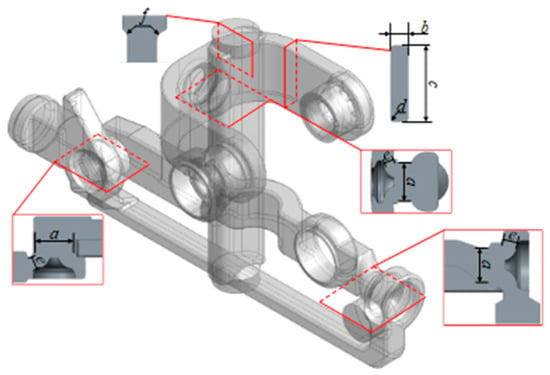
Figure 13.
The geometric model of the fluid domain connected to the boom.

Table 4.
Initial values of flow channel structural design parameters.
4.2. Orthogonal Experimental Design and Analysis
Orthogonal experimental design is a method that considers various experimental factors, levels, and indices, using standard orthogonal tables to conduct a series of experimental designs [32,33]. Based on the conclusions drawn from the previous multi-physics coupling simulation analysis of the arm-connected fluid domain, the following indices are considered: inlet oil area pressure difference (J), outlet oil area pressure difference (K), maximum temperature (L), maximum deformation (M), and maximum stress (N). Six structural design parameters of the flow channel were chosen as experimental factors. Each parameter was tested at five different levels. The levels of the factors are shown in Table 5.

Table 5.
Factor level table.
The L50(511) orthogonal array was employed for the design, with the test scheme and simulation results detailed in Table 6.

Table 6.
Orthogonal experimental table.
Based on the orthogonal test scheme and multi-physics simulation analysis results, an orthogonal test matrix analysis model was established. Range analysis was employed to determine the primary and secondary influences of factor levels on the target parameters [34]. The results of the range analysis are shown in Table 7.

Table 7.
Range analysis of inlet oil area inlet–outlet pressure difference.
The influence degree of each factor on the pressure difference in the inlet area is Rc > Ra > Rb > Rd > Rf > Re, the influence degree of each factor on the pressure difference in the return area is Ra > Rb > Rc > Re > Rd > Rf, and the influence degree of each factor on the temperature is Rd > Rc > Rb > Ra > Rf > Re. The degree of influence of each factor on deformation is Rd > Ra > Rb > Re > Rf > Rc, and the degree of influence of equivalent effect force is Rd > Rc > Ra > Re > Rf > Rb.
4.3. Multiway Valve Structural Parameter Optimization
Based on the orthogonal test data, it was observed that within a defined range of structural parameters, the temperature and maximum deformation do not vary significantly and have minimal impact. Additionally, the pressure loss in the multiway valve, defined as the sum of the pressure losses at the inlet and outlet, is directly related to the operational efficiency of the valve, while the maximum stress is directly related to the service life [35]. Therefore, this study focuses on optimizing the structural parameters of the multiway valve with pressure loss and maximum stress as the primary objectives. A BP neural network was utilized to establish the mapping relationship between the structural parameters and optimization objectives and was combined with the NSGA-II algorithm for multi-objective optimization. The overall optimization scheme is illustrated in Figure 14.
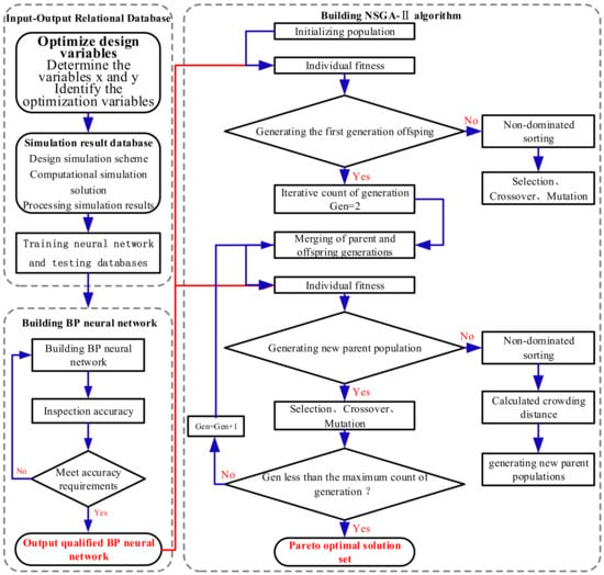
Figure 14.
Parameter optimization route.
The trained BP neural network was tested with two sets of target parameter data to evaluate prediction errors. By comparing the predicted target parameters with the numerical values from simulation experiments, the relative prediction errors were obtained. The comparison details are presented in Table 8. The prediction results show that the BP neural network’s prediction error is relatively small, indicating a high level of reliability. With a population size of 300 and 200 iterations, the Pareto optimal solution set was computed, as shown in Figure 15. Considering manufacturing precision, the final selected structural parameters are: valve spool diameter of 30 mm, flow channel width of 15 mm, flow channel depth of 46 mm, flow channel radius of 2 mm, flow cone width of 7.8 mm, and inlet radius of 10 mm.

Table 8.
Comparison of target parameter prediction results.
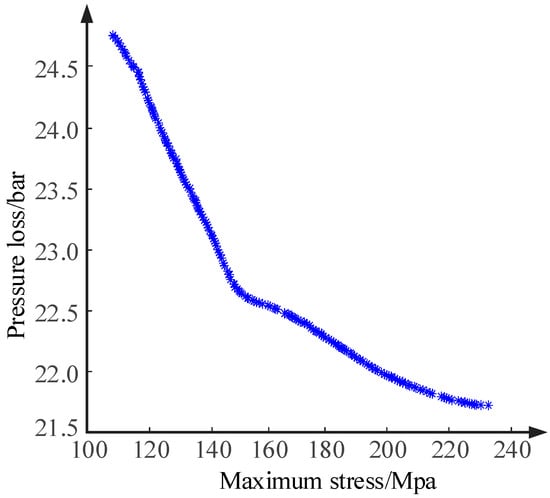
Figure 15.
Pareto Frontier solution set.
Incorporating the above parameters into the multiway valve model and performing simulations using the multi-physical field coupling model, the comparison of each objective parameter before and after optimization is presented in Table 9.

Table 9.
Comparison of target parameter results before and after optimization.
5. Experimental Validation
5.1. Test Bench Construction
The purpose of the multiway valve bench-scale test is to check whether the pressure loss index of the multiway valve can meet the design requirements after optimization design. The schematic diagram of the comprehensive experimental bench for the multiway valve is illustrated in Figure 16. The entire setup consists primarily of a hydraulic system and a data acquisition system. The hydraulic system consists of components such as an oil tank, hydraulic pump, multiway valve, check valve, and relief valve, all connected through hydraulic pipelines. The data acquisition system comprises pressure sensors, flow sensors, smart instruments, data acquisition cards, computers, and corresponding testing software.
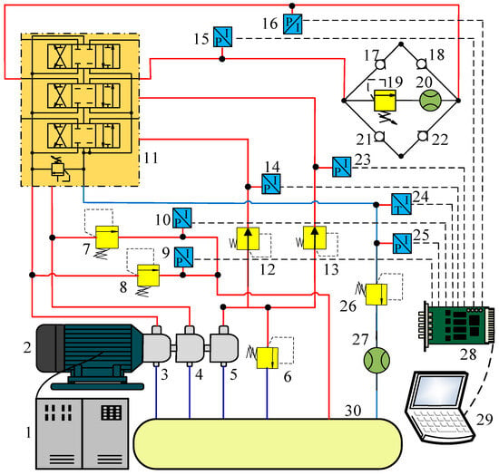
Figure 16.
Schematic diagram of the comprehensive experimental bench for the multiway valve: 1 inverter, 2 motor, 3 variable pump A, 4 variable pump B, 5 quantitative pump, 6 relief valve A, 7 relief valve B, 8 relief valve C, 9 pressure sensor A, 10 pressure sensor B, 11 test multiple valves, 12 pressure reducing valve A, 13 pressure reducing valve B, 14 pressure sensor C, 15 pressure sensor D, 16 pressure sensor E, 17 check valve A, 18 check valve B, 19 relief valve D, 20 flowmeter A, 21 check valve C, 22 check valve D, 23 pressure sensor F, 24 temperature sensor, 25 pressure sensor G, 26 back pressure valve, 27 flowmeter B, 28 signal acquisition card, 29 computer, 30 tank.
When testing the multiway valve, motor 2 drives variable pumps 3 and 4 to supply oil to the test bench of multiway valve 14. Quantitative pump 5 provides pilot oil for multiway valve 14 under test. Relief valves 9 and 10 regulate the operating pressure of the entire hydraulic test system, while overflow valve 19 simulates the load on multiway valve 14 under test. Combining relief valve 19 with check valves 17, 18, 21, and 22 enables bidirectional loading of multiway valve 14 under test. The return oil pressure of multiway valve 14 under test can be adjusted using back pressure relief valve 8.
The experimental bench converts physical quantities in the system, such as pressure and flow rate, into voltage and current signals using components like pressure sensors and flow meters. Among them, the pressure sensor is the most important sensor in the test, which directly affects the measurement error, so the pressure sensor with an accuracy of ±0.075%FS was selected. These signals are automatically collected via a data acquisition card, and the acquired experimental data signals are transmitted to a computer through data cables. This setup enables real-time storage of pressure, flow, and other data during testing and allows monitoring and displaying of the operational status of the experimental bench. Following the schematic diagram, the comprehensive experimental bench for the multiway valve was constructed to conduct tests on the multiway valve, as shown in Figure 17.
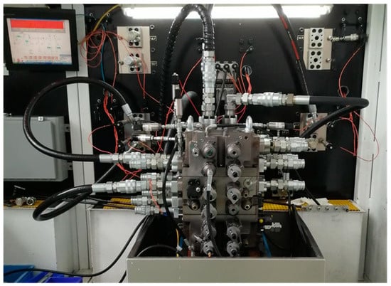
Figure 17.
Testing of the multiway valve.
5.2. Experimental Results and Analysis
Pressure loss experiments were conducted on the flow channels of boom 1 and boom 2 of the multiway valve using the above-mentioned setup. The experimental results were organized and the pressure testing curves for the flow channels of boom 1 and boom 2 of the multiway valve were plotted, as shown in Figure 18.
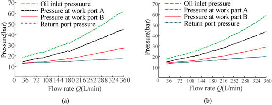
Figure 18.
Multiway valve test boom-connected flow pressure curve: (a) Boom 1 flow pressure curve, (b) Boom 2 flow pressure curve.
The inlet, outlet, and working ports A and B of both boom-connected valves on the multiway valve have been enlarged. The pressure increase was most significant at the inlet port and least at the outlet port. The pressure between the two working ports depended largely on the load. The pressure differential in the inlet region is defined as the difference between the pressure at the inlet port and the pressure at working port A, indicating the pressure loss in the inlet region. Similarly, the pressure differential in the outlet region is defined as the difference between the pressure at the outlet port and the pressure at working port A, indicating the pressure loss in the outlet region. Both of these differentials gradually increased. Due to the trend where these differentials continuously increased in magnitude, it was necessary to calculate the inlet and outlet pressure differentials based on the rated flow. In this study, the rated flow of the multiway valve was selected as 360 L/min. Calculations based on this flow rate showed that the pressure at the inlet ports of boom 1 and boom 2 increased as the flow rate increased. The pressure differential between working ports A and B remained relatively constant, representing the load pressure of the multiway valve. The pressure at the outlet port also remained constant, representing the back pressure of the multiway valve. The pressure differential between the inlet port and working port A indicated the flow path pressure loss, which increased with an increasing flow rate.
The measured results of the flow channel pressure loss of the multiway valve moving with boom 1 and moving boom 2 were calculated and compared with the simulation results as shown in Table 10.

Table 10.
Test results of pressure loss in multiway valve bench test.
As shown in the table, the result error of the inlet and outlet pressure difference in the inlet and outlet area is 5.2%, and the error of the inlet and outlet pressure difference in the return area is 7.7%.
6. Conclusions
Based on the analysis of the pressure loss of the flow field inside the multiway valve channel, this paper carried out the optimization of the flow channel structure parameters. The main research results are as follows:
- (1)
- The distribution of pressure, velocity, and temperature in the flow field of the multiway valve and the force distribution and deformation of the structure field under the influence of the flow field and temperature field were analyzed by multi-physics coupling simulation. Among them, the fluid temperature was usually higher in areas with higher flow rates and lower in areas with lower flow rates, the maximum stress and deformation appeared at the flow channel in the oil inlet area, and the temperature at the flow channel orifice was higher.
- (2)
- The variation range of structural parameters was determined. Combined with the orthogonal test and the multi-physics simulation model, the variation rules of performance indexes such as oil inlet pressure difference, oil return pressure difference, temperature, maximum deformation, and maximum stress of different orthogonal test groups were revealed. The primary and secondary order of influence of key structural parameters on performance indexes was obtained by using range analysis.
- (3)
- Based on the analysis of orthogonal test data, the multi-parameter and multi-objective optimization was carried out with the pressure loss and maximum stress as the optimization objectives. After optimization, the pressure loss and maximum stress of the multiway valve were reduced by 9.0% and 40.7%, respectively. A test bench was set up to test the optimized boom-connected multiway valve. The error of the pressure difference between the inlet and outlet of the simulation model is 5.2% in the inlet and outlet of the oil inlet, and the outlet of the simulation model is 7.7%.
This paper only studies the multiway valve under steady state conditions and does not specifically analyze the multiway valve with valve openings or load change under actual working conditions. In the future, more working conditions need to be analyzed and studied, and the simulation data and physical field laws in a steady state may not be exactly the same as those under dynamic conditions. Therefore, the future will be based on the steady–state study of the multiway valve to carry out its transient research, and it will not be limited to the boom-connected excavator multiway valve, but will also be applied to multiple valves in other construction machinery.
Author Contributions
Conceptualization, X.Y., Z.Z. (Ze Zheng), N.C., Z.Z. (Zongjin Zhang), X.L. and Z.M.; methodology, Z.Z. (Ze Zheng) and Z.M.; software, Z.Z. (Ze Zheng); validation, X.Y., Z.Z. (Ze Zheng), N.C., Z.Z. (Zongjin Zhang), X.L. and Z.M.; formal analysis, Z.Z. (Ze Zheng) and Z.Z. (Zongjin Zhang); investigation, Z.Z. (Ze Zheng), N.C., Z.Z. (Zongjin Zhang) and Z.M.; resources, X.Y.; data curation, Z.Z. (Ze Zheng) and Z.M.; writing—original draft preparation, Z.Z. (Ze Zheng) and Z.M.; writing—review and editing, Z.Z. (Ze Zheng) and N.C.; visualization, Z.Z. (Ze Zheng); supervision, X.Y. and X.L.; project administration, X.Y. and X.L.; funding acquisition, X.Y. and X.L. All authors have read and agreed to the published version of the manuscript.
Funding
This research was funded by Science and Technology Project of Hebei Education Department of China (Grant No. ZD2022052), Hebei Province Central Leading Local Science and Technology Development Fund Project (Grant No. 246Z1903G), National Natural Science Foundation of China (Grant No. 52175066).
Data Availability Statement
The datasets used or analyzed during the current study are available from the corresponding author on reasonable request.
Acknowledgments
The authors acknowledge support from Li jie Zhang for his assistance in the research.
Conflicts of Interest
The authors declare no conflict of interest.
References
- Min, C.; Li, H.; Gao, X.; Wang, K.; Xie, L. Numerical investigation of convective heat transfer enhancement by a combination of vortex generator and in-tube inserts. Int. Commun. Heat Mass Transf. 2021, 127, 105490. [Google Scholar] [CrossRef]
- Hu, B.; Zhu, H.; Ding, K.; Zhang, Y.; Yin, B. Numerical investigation of conjugate heat transfer of an underwater gate valve assembly. Appl. Ocean Res. 2016, 56, 1–11. [Google Scholar] [CrossRef]
- Okhotnikov, I.; Abuowda, K.; Noroozi, S.; Godfrey, P. Numerical and experimental investigation of the metering characteristic and pressure losses of the rotary tubular spool valve. Flow Meas. Instrum. 2020, 71, 101679. [Google Scholar] [CrossRef]
- Olivetti, M.; Monterosso, F.G.; Marinaro, G.; Frosina, E.; Mazzei, P. Valve geometry and flow optimization through an automated DOE approach. Fluids 2020, 5, 17. [Google Scholar] [CrossRef]
- Herakovič, N.; Duhovnik, J.; Šimic, M. CFD simulation of flow force reduction in hydraulic valves. Teh. Vjesn./Tech. Gaz. 2015, 22, 453–463. [Google Scholar] [CrossRef]
- Simic, M.; Herakovic, N. Reduction of the flow forces in a small hydraulic seat valve as alternative approach to improve the valve characteristics. Energy Convers. Manag. 2015, 89, 708–718. [Google Scholar] [CrossRef]
- Wu, J.; Chen, L.; Luo, Y.; Zeng, C.; Li, X.; Lu, F. Analysis of Flow Field of Channel and Structural Optimization for Speed Switching Slide Valve in a Hydraulic Excavator Based on CFD. Mach. Tool Hydraul. 2013, 41, 131–133. [Google Scholar]
- Yang, Q.; Wang, X.Z.; Liu, M.Y.; Hu, J.; Zhang, Z.G. Optimization of Valve Block Shape Using CFD. Appl. Mech. Mater. 2012, 190, 133–138. [Google Scholar] [CrossRef]
- Wang, Y.; Xu, Z.; Meng, D.; Liu, L.; Fang, Z. Multi-Physical Field Coupling Simulation and Experiments with Pulse Electrochemical Machining of Large Size TiAl Intermetallic Blade. Metals 2023, 13, 985. [Google Scholar] [CrossRef]
- Liu, J.; Yu, S.; Yang, S.; Zhang, Y.; Fan, X.; Gao, B. Numerical Studies on the Performance of the PCM Mesh-Finned Heat Sink Base on Thermal-Flow Multiphysics Coupling Simulation. Energies 2020, 13, 4658. [Google Scholar] [CrossRef]
- Li, Z.; Cao, B.; Dai, Y. Research on multi-physics coupling simulation for the pulse electrochemical machining of holes with tube electrodes. Micromachines 2021, 12, 950. [Google Scholar] [CrossRef]
- Wu, J.; Chen, J.; Cai, X.; Zou, C.; Yu, C.; Cui, Y.; Zhang, A.; Zhao, H. A review of molten salt reactor multi-physics coupling models and development prospects. Energies 2022, 15, 8296. [Google Scholar] [CrossRef]
- Yuan, X.; Wang, W.; Zhu, X.; Zhang, L. Theoretical Model of Dynamic Bulk Modulus for Aerated Hydraulic Fluid. Chin. J. Mech. Eng. 2022, 35, 121. [Google Scholar] [CrossRef]
- Hong, C.; Qiao, S.; Shah, A.A. Influence of oil temperature on pressure distribution and flow force of valve core. Int. J. Hydromechatron. 2023, 6, 342–358. [Google Scholar] [CrossRef]
- Li, M.; Zheng, S.; Wei, M. Flow Loss Analysis and Structural Optimization of Multiway Valves for Integrated Thermal Management Systems in Electric Vehicles. Energies 2023, 16, 5040. [Google Scholar] [CrossRef]
- Xu, L.; Ma, H.; Ren, D. Numerical simulation for multi-way valves and fit clearance research based on heat–fluid–solid coupling. J. Eng. 2019, 2019, 247–252. [Google Scholar] [CrossRef]
- Peng, C.; Luo, Y.; Jin, Y. Thermal Fluid-Solid Coupling and Thermal Stress Analysis of Vacuum Valve Based on CFD. In Proceedings of the Seventh Asia International Symposium on Mechatronics: Volume I; Springer: Singapore, 2020. [Google Scholar]
- Kazama, T. Thermohydrodynamic lubrication model of a slipper in swashplate type axial piston machines-validation through experimental data. Int. J. Hydromechatron. 2018, 1, 259–271. [Google Scholar] [CrossRef]
- Tan, W.; Chen, Z.; Li, Z.; Yan, H. Thermal-Fluid-Solid Coupling Simulation and Oil Groove Structure Optimization of Wet Friction Clutch for High-Speed Helicopter. Machines 2023, 11, 296. [Google Scholar] [CrossRef]
- Tang, J.; Xie, W.; Wang, X.; Chen, C. Simulation and analysis of fluid–solid–thermal unidirectional coupling of near-space airship. Aerospace 2022, 9, 439. [Google Scholar] [CrossRef]
- Amirante, R.; Catalano, L.A.; Poloni, C.; Tamburrano, P. Fluid-dynamic design optimization of hydraulic proportional directional valves. Eng. Optim. 2014, 46, 1295–1314. [Google Scholar] [CrossRef]
- Shankar Bhattacharjee, K.; Kumar Singh, H.; Ray, T. Multi-objective optimization with multiple spatially distributed surrogates. J. Mech. Des. 2016, 138, 091401. [Google Scholar] [CrossRef]
- Zong, C.; Shi, M.; Li, Q.; Liu, F.; Zhou, W.; Song, X. Design optimization of a nuclear main steam safety valve based on an E-AHF ensemble surrogate model. Nucl. Eng. Technol. 2022, 54, 4181–4194. [Google Scholar] [CrossRef]
- Geneid, A.A.; Atia, M.R.A.; Badawy, A. Multi-objective optimization of vertical-axis wind turbine’s blade structure using genetic algorithm. J. Eng. Appl. Sci. 2022, 69, 1–19. [Google Scholar] [CrossRef]
- Li, C.; Liu, X.; Wang, X.; Chen, J.; Wang, Y. Optimization of multi-way valve structure in digital hydraulic system of loader. Energies 2021, 14, 700. [Google Scholar] [CrossRef]
- Wang, S.; Ma, X.; Hu, Z.; Sun, S. Multi-Parameter Optimization of Heat Dissipation Structure of Double Disk Magnetic Coupler Based on Orthogonal Experimental Design. Energies 2022, 15, 8801. [Google Scholar] [CrossRef]
- Caixeta, P.R.; Marques, F.D. Multi-objective Optimization of an Aircraft Wing Design with Respect to Structural and Aeroelastic Characteristics using Neural Network Metamodel. J. Braz. Soc. Mech. Sci. Eng. 2018, 40, 1–11. [Google Scholar] [CrossRef]
- Yang, M.; Zhang, Y.; Ai, C.; Yan, G.; Jiang, W. Multi-objective optimisation of K-shape notch multi-way spool valve using CFD analysis, discharge area parameter model, and NSGA-II algorithm. Eng. Appl. Comput. Fluid Mech. 2023, 17, 2242721. [Google Scholar] [CrossRef]
- Duan, B.; Luo, M.; Yuan, C.; Luo, X. Multi-objective hydraulic optimization and analysis in a minipump. Sci. Bull. 2015, 60, 1517–1526. [Google Scholar] [CrossRef]
- Corbera, S.; Olazagoitia, J.L.; Lozano, J.A. Multi-objective global optimization of a butterfly valve using genetic algorithms. ISA Trans. 2016, 63, 401–412. [Google Scholar] [CrossRef]
- Lu, Y. Handbook of Hydraulic Pneumatic Technology; China Machine Press: Beijing, China, 2004; pp. 352–353. [Google Scholar]
- Bakhshpoori, T.; Asadi Abadi, A. Orthogonal learning metaheuristics for structural optimization. Neural Comput. Appl. 2023, 35, 19497–19521. [Google Scholar] [CrossRef]
- Peng, H. Orthogonal experimental design and data analysis method. Metrol. Meas. Technol. 2009, 36, 39–40+42. [Google Scholar]
- Yang, X.L.; Xia, Y.X.; Huang, G. Numerical analysis and orthogonal optimization design of magnetic fluid reciprocating seals. J. Magn. Magn. Mater. 2024, 592, 171782. [Google Scholar] [CrossRef]
- Yang, G.; Qiao, J.; Song, Z.; Dai, J. The service life analysis of drilling pump valve. J. Vib. Shock 2010, 29, 58–61+237. [Google Scholar]
Disclaimer/Publisher’s Note: The statements, opinions and data contained in all publications are solely those of the individual author(s) and contributor(s) and not of MDPI and/or the editor(s). MDPI and/or the editor(s) disclaim responsibility for any injury to people or property resulting from any ideas, methods, instructions or products referred to in the content. |
© 2024 by the authors. Licensee MDPI, Basel, Switzerland. This article is an open access article distributed under the terms and conditions of the Creative Commons Attribution (CC BY) license (https://creativecommons.org/licenses/by/4.0/).