Abstract
Torque ripple in a brushless DC motor (BLDCM) seriously restricts its application in high-performance fields. This paper proposes a commutation torque ripple suppression strategy based on a Zeta converter. The expected output voltage of a Zeta converter that suppresses the commutation torque ripple is obtained, according to the effect of the duty ratio of the Zeta converter on the turn-off phase freewheeling duration and the turn-on phase rising duration, during commutation. Based on the analysis of the dynamic response of the Zeta converter, the Zeta converter is adjusted to ensure that the Zeta converter reaches stability in sufficient time. During the commutation, the output voltage of the Zeta converter is connected to the main circuit to reduce the torque ripple during commutation, and the expected regulated duty cycle of the Zeta converter during the next commutation is calculated to adjust the output voltage of the Zeta converter. Based on this analysis, the experimental results verify the effectiveness of the proposed method.
1. Introduction
Brushless DC motors (BLDCMs) have received wide attention in regard to their many industrial applications due to its advantages, namely its high-power density, simple driving method, and easy maintenance [,]. However, due to the serious commutation torque ripple problem associated with the two-phase conduction mode, the stability of the BLDCM is reduced, which restricts its application in fields involving high precision [,,]. During commutation of the BLDCM, the current cannot be abruptly changed due to the existence of inductance during motor winding, leading to the generation of commutation torque ripple [,,,]. On this basis, domestic and foreign scholars have performed lots of research on the commutation torque ripple of the BLDCM, from the perspective of circuit topology improvement and control strategy optimization.
In [], the impact of stator iron loss and current-loop delay on torque control aimed at minimizing copper losses in a BLDCM are analyzed, and an improved control strategy is proposed, effectively reducing iron loss and torque ripple, while enhancing the overall efficiency of the motor. In [], an efficient Maximum Power Point Tracking (MPPT) strategy using Ripple Correlation Control (RCC) is presented, which optimizes the power output from the PV system and significantly reduces torque ripple in a BLDCM-driven pumping system under varying solar irradiance conditions. In [], an optimized switching technique focused on harmonic minimization is introduced, significantly improving the overall efficiency of the BLDC motor driving circuit and effectively reducing the torque ripple. In [], an enhanced PWM-OFF-PWM technique is proposed, which modulates PWM signals during braking to smooth torque transitions, significantly reducing the commutation torque ripple and improving braking performance. Moreover, different voltage vectors are selected based on the output of the torque hysteresis comparator for different speed ranges. However, the three-phase conduction mode not only increases the switching loss of the inverter, but also causes serious error accumulation due to the set dead-zone time in the real system.
The buck–boost auxiliary circuit is designed in the front end of traditional inverters [,]. Based on this, the effects of different vector combinations on the commutation torque ripple and rotation speed are analyzed during commutation and conduction, respectively. The optimal vector is obtained to suppress the commutation torque ripple in two modulation cycles. In [], the influence of three-level inverters on the motor torque is analyzed. The improved combination of the SEPIC converter and the three-level inverter is used to achieve commutation torque ripple suppression. However, the topology of this method is complex, which reduces the commutation torque ripple and increases the overall loss in the system. In [], the auxiliary step-up front-end converter is designed based on a flyback transformer. On this basis, the relationship between the output voltage of the front end and the back EMF is adjusted to suppress the commutation torque ripple. However, this method uses a flyback transformer, which requires a higher performance capacitance and lacks analysis on the dynamic response of the auxiliary step-up front-end converter when the auxiliary circuit is commutated. In [], a method utilizing an improved quasi-Z-source network is introduced, which optimizes the rise and fall times of phase currents during commutation, effectively reducing torque ripple in BLDC motors.
Unlike the buck–boost circuit, SEPIC converter, and flyback transformer, the unique inductance structure of the Zeta converter allows for continuous current output at a lower current ripple [,]. Although the Zeta converter consists of the same number of components as the Cuk converter [,], the Cuk converter is an inverting buck–boost circuit. Unlike the Cuk converter, the Zeta converter is a noninverting buck–boost circuit, which can eliminate the impact of negative voltage on the circuit, and it has a faster dynamic response in terms of the system [,]. Based on the advantages of the Zeta converter, combined with the application of other converters to BLDCM torque ripple suppression, this article analyzes the suppression of BLDCM commutation torque ripple based on the Zeta converter and provides the corresponding control strategies. Due to the existence of motor inductance, the turn-off phase current and turn-on phase current of the BLDCM cannot be abruptly changed during the commutation process, which results in the turn-off phase freewheeling duration not being equal to the turn-on phase rising duration, so that the noncommutated phase current changes, resulting in commutation torque ripple [,].
In this paper, first, based on the turn-off phase freewheeling duration and turn-on phase rising duration being equal, the adjusted duty ratio of the Zeta converter can be obtained. Then, the dynamic response of the Zeta converter and the commutation duration are analyzed. Considering that the expected output voltage of the Zeta converter without commutation torque pulsation remains the same during the two adjacent commutation cycles, according to the motor speed and load current at the previous commutation, the duty ratio of the Zeta converter under the stable operation of the motor can be adjusted. On this basis, the strategy for the adjustment of the noncommutation and commutation phases is constructed.
In Section 1, the article highlights the importance of BLDC motors in industrial applications and the challenge of commutation torque ripple, and discusses various strategies proposed to mitigate this issue, focusing on the advantages of using a Zeta converter. In Section 2, the analysis of commutation torque ripple reveals the sources of the ripple and explains how the Zeta converter can control the output voltage during commutation to reduce it. In Section 3, the proposed strategy for suppressing commutation torque ripple using the Zeta converter is detailed, including the design of a back-EMF observer to enhance system stability. And the dynamic response of the Zeta converter is analyzed, demonstrating its effectiveness in maintaining a stable output voltage during motor commutation. In Section 4, experimental results validate the proposed method using a 3.5 kW BLDC motor, showing a significant reduction in the torque ripple and improved performance compared to traditional methods. In Section 5, the conclusions affirm the effectiveness of the Zeta converter-based method in reducing commutation torque ripple and enhancing the stability and performance of BLDC motors.
2. Analysis of Commutation Torque Ripple in BLDCM
2.1. Equivalent Model of BLDCM with Zeta Converter
The stator winding of the BLDCM adopts a three-phase star connection method. Due to the existence of motor inductance and the impact of the motor speed, current, and conduction mode, the turn-off phase freewheeling duration is not equal to the turn-on phase rising duration, resulting in commutation torque ripple [,]. Therefore, the output voltage is controlled by adding the Zeta converter at the front end of the three-phase inverter, so that the conversion rates of the turn-off phase and turn-on phase currents are equal during commutation. Figure 1 displays the equivalent model of the driving circuit topology and the motor.
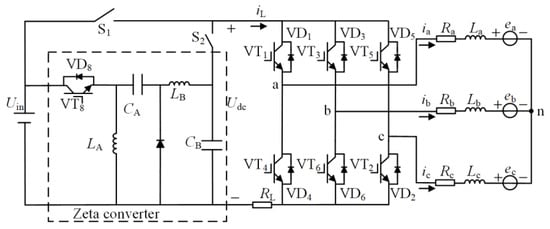
Figure 1.
Topology structure of the BLDCM driving circuit with the Zeta converter.
The three-phase stator windings of the motor are assumed to be symmetric. The nonlinear changes in the winding resistance and inductance during the operation of the motor are not taken into account. The voltage equation of the BLDCM is obtained as:
where the phase current is ix, the trapezoidal back EMF is ex, the terminal-to-neutral point voltage is Uxn, the winding resistance is Rx = R, the winding inductance is Lx = L, and the phase is x = a, b, c. At the rotor mechanical angular velocity ω, the electromagnetic torque Te is obtained as:
2.2. Analysis of Commutation Torque Ripple Based on Zeta Converter
During motor operation, Udc is the output voltage of the Zeta converter. It can be obtained as:
where D is the duty ratio of the Zeta converter and Uin is the input voltage of the Zeta converter, which is the rated voltage of the motor. Taking the medium-speed stage of the BLDCM as an example, the impact of the change in the duty ratio D on the current and torque is analyzed by controlling the output voltage value of the Zeta converter during motor commutation.
When D = 50%, the turn-off phase freewheeling duration is equal to the turn-on phase rising duration, so that the noncommutation current and the electromagnetic torque remain constant, as shown in Figure 2a. When D < 50%, the turn-off phase freewheeling duration is less than the turn-on phase rising duration, so that the noncommutation current decreases, resulting in a decrease in the electromagnetic torque, as shown in Figure 2b. When D > 50%, the turn-off phase freewheeling duration is greater than the turn-on phase rising duration, so that the noncommutation current increases, resulting in an increase in the electromagnetic torque, as shown in Figure 2c. Analogously, the increase or decrease in electromagnetic torque is also influenced by the output voltage of the Zeta converter during low-speed and medium-speed commutation. Therefore, the condition for suppressing commutation torque ripple is that the turn-off phase freewheeling duration and turn-on phase rising duration are equal, and the commutation torque can be controlled by adjusting the output voltage of the Zeta converter.

Figure 2.
Influence of duty ratio D on the three-phase current in the medium-speed stage: (a) D = 50%; (b) D < 50%; (c) D > 50%.
3. Strategy of Suppressing Commutation Torque Ripple Based on Zeta Converter
3.1. Conditions for Suppressing Commutation Torque Ripple in BLDCM
Based on the general solution of the first-order nonhomogeneous differential equation, Equation (4) can be obtained from (1). Equation (4) is the relationship between the current during the commutation process and time.
In the process of motor commutation, the turn-off phase freewheeling duration is toff. The turn-on phase rising duration is ton. The starting current value of the turn-off phase and the expected final value of the turn-on phase current are sI, where s is the sign function, s = 1 represents the upper-tube commutation, s = −1 represents the lower-tube commutation, and I is the absolute value of the starting current.
If during the commutation process, x represents the turn-off phase. When t = 0, then ix(0) = sI. When t = toff, then ix(toff) = 0. According to (4), the constant C1 and the turn-off phase freewheeling duration toff can be obtained as:
If during the commutation process, x represents the turn-on phase. When t = 0, then ix(0) = 0. When t = ton, then ix(ton) = sI. According to (4), the constant C2 and the turn-on phase rising duration ton can be obtained as:
The upper-tube commutation process from A+C− to B+C− is used as an example of the analysis. In Figure 3, VT1 is turned off, VT3 is turned on, VT2 remains constant, and VD4 freewheels. Ignoring the on-voltage drop of the switch tube and the freewheeling diode, the three-phase voltage meets Ucn − Uan = 0, Ubn − Ucn = sUdc, and the three-phase current meets ia + ib + ic = 0. According to (1), the voltage during the turn-off phase and the turn-on phase can be obtained as:
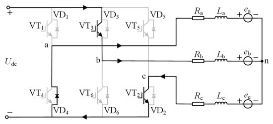
Figure 3.
The commutation process from A+C− to B+C−.
When A+C− to B+C− commutation occurs, ea = sE, eb = sE, ec = −sE, E is the amplitude of the back EMF, that is, E = kω, k is the back EMF coefficient, ω is the motor speed, and the initial value of the turn-off phase current is sI.
On this basis, substituting (7) into (5) and (6), the turn-off phase continuation freewheeling duration toff and the turn-on phase rising duration ton can be obtained as:
Similarly, the analysis of the lower-tube commutation also satisfies (8). According to (3) and (8), the corresponding 3D graph is shown in Figure 4.
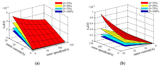
Figure 4.
The relationship between the turn-off phase freewheeling duration, the turn-on phase rising duration, the duty ratio of the Zeta converter, stator current, and rotor speed: (a) the turn-off phase freewheeling duration; (b) the turn-on phase rising duration.
When the speed and current are fixed, the Udc can be obtained as (9), and the expected duty ratio D of the Zeta converter can be obtained as (10), by taking toff = ton as the condition of no commutation torque ripple, according to (3) and (8). The corresponding 3D graph is shown in Figure 5.
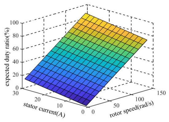
Figure 5.
The expected duty ratio varies with the stator current and rotor speed.
3.2. Design of Back-EMF Observer for Brushless DC Motor
The structure of the observer could be seen in Figure 6. Based on the above analysis and considering the impact of the back EMF on the torque ripple suppression conditions of the brushless DC motor as stated in Equation (10), using the back-EMF constant to calculate the back EMF can lead to calculation errors due to the neglect of the system’s nonlinear effects, which in turn affects the results from Equation (10). Therefore, to enhance the suppression effect on the torque ripple in the brushless DC motor, this paper designs a back-EMF observer for the brushless DC motor and proves its stability.
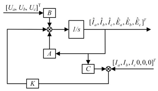
Figure 6.
The structure of the observer.
Based on voltage Equation (1) of the mathematical model of a BLDC motor, this paper chooses the state vector x = [Ia, Ib, Ic, Ea, Eb, Ec]T. The system’s state equation can be expressed as:
where:
The observer takes the form:
where is the estimated output, is the actual measured output, and C is the output matrix:
Define the error . The error dynamics equation is:
Based on (14), the error is:
To prove system stability, it needs to show that all the eigenvalues of the matrix A − KC lie in the left half-plane, by choosing a Lyapunov function V(e) = eTPe, where P is a symmetric positive definite matrix. Solve the Lyapunov equation as follows:
where Q is a symmetric positive definite matrix. If positive definite matrices P and Q can be found, the system is asymptotically stable.
Based on (14), the structure of the observer can be derived as shown below:
The specific steps for solving P, Q, and K are as follows: First, determine the system matrix A and the input matrix B, based on the motor parameters shown in Table 1. Then, select the desired closed-loop poles λn (n = 1, 2, 3, 4, 5, 6) based on these motor parameters. The poles for the BLDC motor controller are calculated to ensure system stability. Following this, the poles for the observer are initially chosen to be 5–10 times the real part of the controller poles, which is a common criterion for ensuring a fast and accurate response of the observer without introducing excessive noise sensitivity. These initial selections are further refined through simulation and experimental adjustments to optimize the performance of the observer. Finally, the pole placement function ‘place(A, C, λ)’ in Python is used to solve the gain matrix K, and the Lyapunov solver function ‘solve_continuous_lyapunov(A − KC, −Q)’ is employed to solve P, where Q is chosen as the identity matrix.

Table 1.
Main parameters of the BLDCM and Zeta converter.
3.3. Analysis of the Dynamic Response of the Zeta Converter
The Zeta converter converts the DC voltage into a high-frequency voltage through a high-frequency vibration circuit and outputs the required DC voltage through an inductor pulse transformation and capacitor filtering. The topology is shown in Figure 1. Due to the presence of inductance and capacitance in the circuit, it can be approximated as an RLC second-order system, and the equivalent second-order differential equation of the Zeta converter is (19), without considering the motor inductance.
where R represents the equivalent load of the Zeta converter, C represents the equivalent filter capacitor of the Zeta converter, L represents the equivalent inductance of the Zeta converter, Udc(t) represents the Zeta converter output voltage, and Uin(t) represents the Zeta converter input voltage. The natural frequency ωn and the damping ratio ξ can be obtained as:
The stability of the second-order system of the Zeta converter depends on ξ. Based on the analysis of the dynamic response of the second-order system in the underdamped state, the error between the actual response of the system and the steady-state output can be obtained by combining (19) and (20).
Assuming ξ 0.8, bringing ξ = 0.8 into the denominator of (21), and selecting the steady-state error = 0.05 or 0.02, the expression of the adjustment time ts is obtained as:
On this basis, the parameters of C and L can be selected by considering the power level of the actual motor. The dynamic response of the Zeta converter is analyzed according to Table 1. The adjustment characteristics concern the start of the Zeta converter and the step response of the expected output voltage from 200 V to 300 V.
As shown in Figure 7, the adjustment process of the Zeta converter takes 10 ms, while the commutation duration of the BLDCM is generally tens or hundreds of microseconds. Although the dynamic response of the Zeta converter can be improved by reducing its inductance and capacitance values, it also exacerbates the ripple of the output voltage and current, leading to the unstable output of the Zeta converter. Because the adjustment time of the Zeta converter is much longer than the commutation duration of the BLDCM, it is impossible to achieve real-time changes in the output voltage of the Zeta converter during the commutation duration of the motor. Considering that the expected output voltage of the Zeta converter without commutation torque pulsation remains the same in the two adjacent commutation cycles, according to the motor speed and load current at the previous commutation, the duty ratio of the Zeta converter under the stable operation of the motor can be adjusted by (10), and the expected output voltage of the Zeta converter can be adjusted in real time.
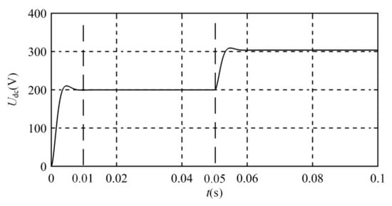
Figure 7.
Adjustment characteristics during the Zeta converter startup and step response.
3.4. Implementation of Commutation Torque Ripple Suppression Strategy
When the motor runs in the noncommutation region, the S1 is turned on and the S2 is turned off, Udc = Uin. During that time, the BLDCM drive system is controlled with traditional double-loop PI regulators (i.e., the speed loop and the current loop), and the speed and torque can achieve high stability, such as in Figure 8a. At the same time, the Zeta converter is disconnected from the inverter circuit and adjusted according to (10) to achieve stability.

Figure 8.
Switch states of S1 and S2 in the mode selection circuit: (a) voltage output mode in the noncommutation region; (b) voltage output mode in the commutation region.
When the motor runs in the commutation region, S1 is turned off and S2 is turned on. The Zeta converter is connected to the main circuit; Udc is the output voltage of the Zeta converter, such as in Figure 8b. According to the motor speed and load current at the previous commutation, the duty ratio of the Zeta converter under the stable operation of the motor can be adjusted by (10). On this basis, a similar analysis can be performed according to (5)–(7), where d is the duty ratio of the inverter circuit. The expected duty ratio of the inverter circuit is obtained as:
On the basis of the above analysis, the BLDCM control system is designed. Figure 9 shows the configuration of the proposed BLDCM control system. The working status of the motor is judged by the Hall signal. If the motor works in the noncommutation region, the system uses double-loop PI regulators to control the stable operation of the motor. If the motor works in the commutation region, on the basis of the Zeta converter output voltage adjustment after the previous commutation, the commutation time and the duty ratio of the inverter are calculated according to (10) and (15) to suppress the motor commutation torque ripple. At the end of commutation, the expected output voltage of the Zeta converter is adjusted according to (10) to ensure that the Zeta converter can output a stable expected voltage at the next commutation.
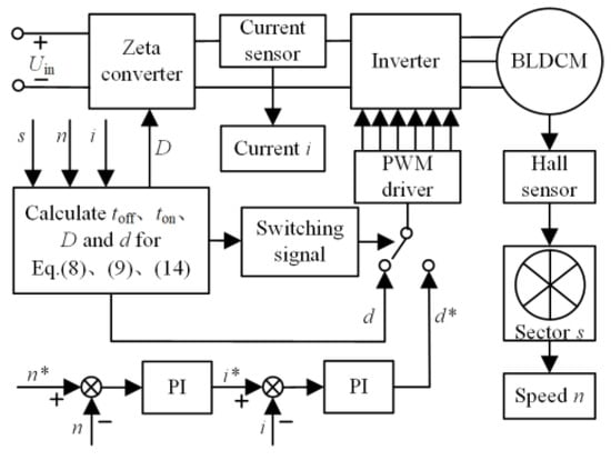
Figure 9.
Configuration of the proposed BLDCM control system.
4. Simulation and Experimental Results
The experimental platform is set up based on a 3.5 kW BLDCM to verify the effectiveness of the proposed method, as shown in Figure 10. The system controller is DSP (TMS320F28335). The three-phase inverter is composed of IPM (PM50RL1A060). The Zeta converter is composed of IGBT (FF75R12RT4). The specific parameters of the BLDCM and the Zeta converter are shown in Table 1. The modulation method of the three-phase inverter is ON-PWM, and the switching frequency of the three-phase inverter is 20 kHz.
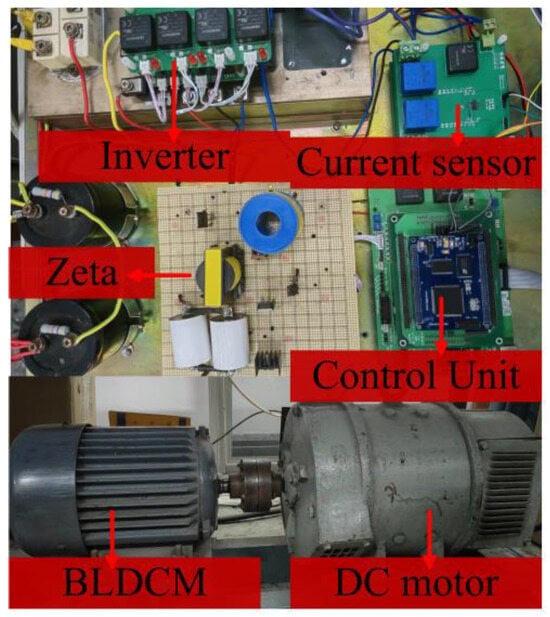
Figure 10.
BLDCM experimental system setup.
The torque ripple is defined as:
where Tp-p is the peak–peak value of the torque and Tavg is the average torque.
Kr = Tp-p/Tavg × 100%
As shown in Figure 11, the proposed method maintains a consistent rate of change during the turn-off phase and turn-on phase currents compared with traditional methods, while the noncommutation phase currents remain constant. The commutation torque ripple can be suppressed.
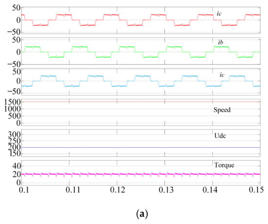
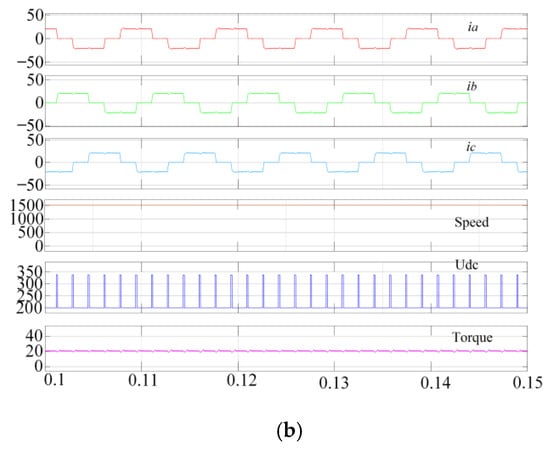
Figure 11.
Simulation results, with the torque reference value being 20 N·m and the speed being 1500 r/min: (a) traditional control strategy; (b) proposed method.
Figure 12 shows the experimental results when the motor runs at the torque reference value of 10 N·m and a speed of 1000 r/min. Figure 12a shows the experimental results for the traditional double-loop PI. The value of Kr is higher than 30%. Figure 12b shows the experimental results for the proposed method based on the Zeta converter. The value of Kr is less than 15%. Compared to traditional methods, the commutation time of the proposed method has also been significantly reduced, as shown in Figure 12.
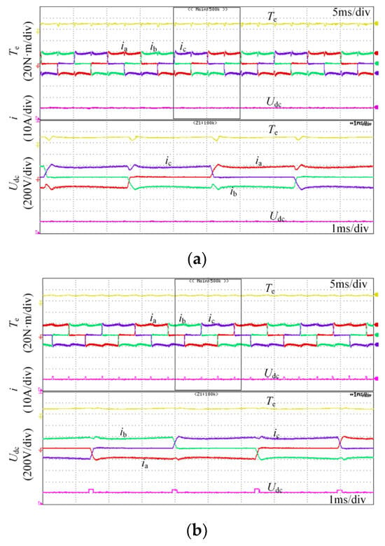
Figure 12.
Experimental results, with the torque reference value being 10 N·m and the speed being 1000 r/min: (a) traditional control strategy; (b) proposed method.
Figure 13 shows the experimental results when the motor runs at the torque reference value of 20 N·m and a speed of 1500 r/min. As shown in Figure 13a, the value of Kr is higher than 45%. Figure 13b shows the experimental results presented in reference []. Figure 13c shows the experimental result for the proposed method based on the Zeta converter. The value of Kr is less than 20% in the proposed method. Compared with traditional methods and the method in [], the proposed method maintains a consistent rate of change during the turn-off phase and turn-on phase currents, while the noncommutation phase currents remain constant. It can be seen that using the traditional method, the commutation time of the BLDCM is higher than 300 us, and after an improvement, the commutation time is lower than 200 us. Therefore, the BLDCM drive system optimized by the Zeta converter not only reduces the torque ripple, but also effectively shortens the commutation time.
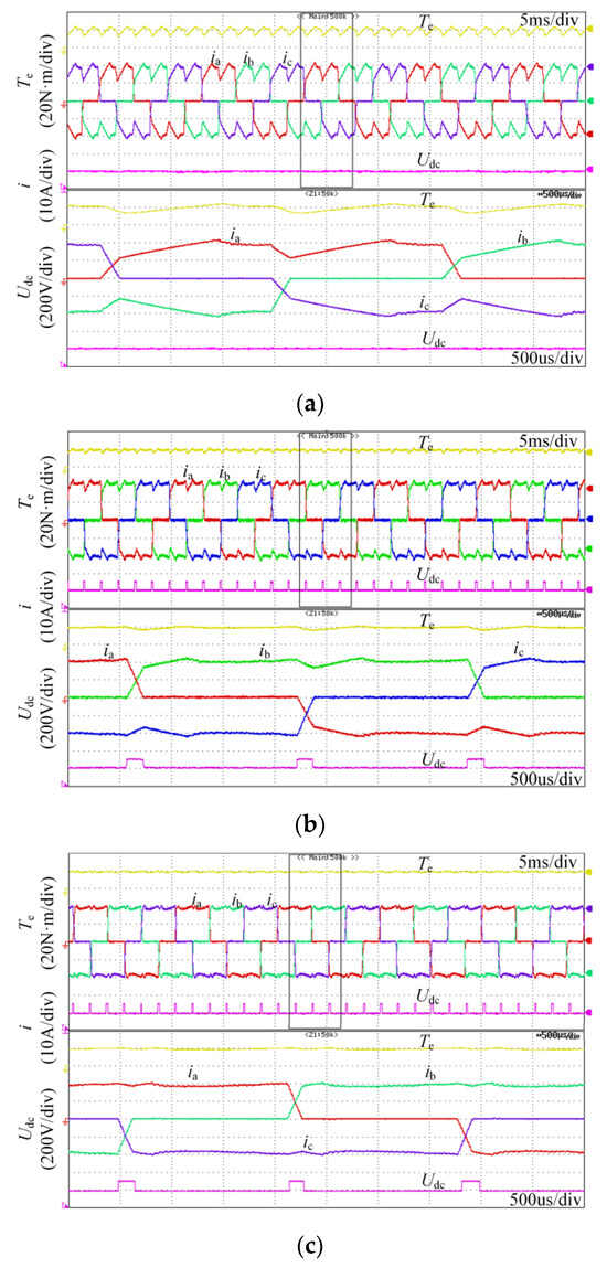
Figure 13.
Experimental results, with the torque reference value being 20 N·m and the speed being 1500 r/min: (a) traditional control strategy; (b) control strategy in []; (c) proposed method.
The standard deviation to indicate a quantitative value for the torque ripple is as follows:
Based on the stability and dynamic experimental results, the proposed method compared to the traditional method shows that the value of the torque ripple percentage falls within the range of 15% to 20%, and the standard deviation of the torque ripple is between 1.5 Nm and 2 Nm under full-load conditions, effectively reducing the torque ripple in the brushless DC motor. To analyze the suppression effect of torque pulsation, this paper provides a comparative table illustrating torque ripple suppression under different drive strategies and various operating conditions. This provides for a clearer observation of the effectiveness of the proposed method in suppressing torque ripple in BLDC motors, as shown in Table 2.

Table 2.
Comparative table on torque ripple suppression under different drive strategies.
Figure 14 shows the output current and voltage waveforms of the Zeta converter under the rated conditions. From Figure 14, it can be seen that under the influence of the Zeta converter, the turn-on phase current can rapidly increase, effectively reducing the torque ripple.
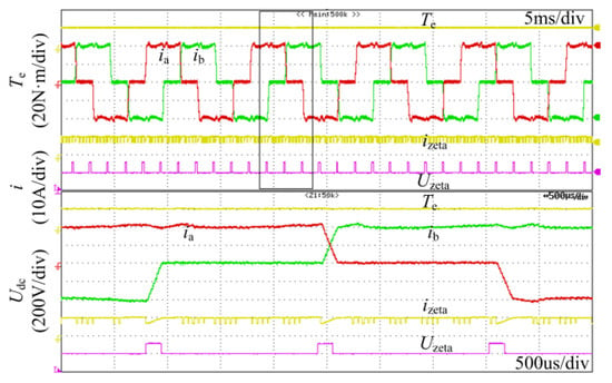
Figure 14.
Output current and voltage waveforms of the Zeta converter.
Figure 15 shows the experimental results for the method proposed in this paper under accelerated operation and dynamic load. Setting the reference speed as the slope command, the speed is accelerated from 1000 r/min to 1500 r/min within 1 s, and the load torque is set to 20 N·m, as shown in Figure 15a. The load torque is changed from 10 N·m to 20 N·m, and the speed is 1500 r/min, as shown in Figure 15b.
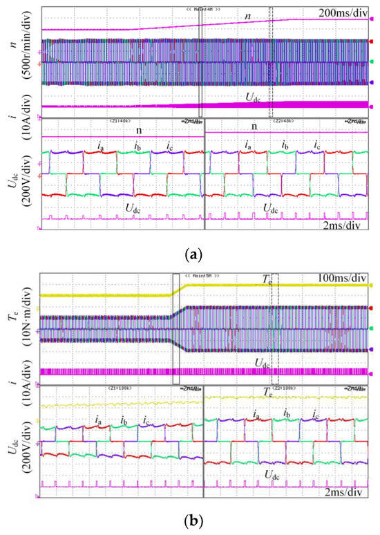
Figure 15.
Experimental results during accelerated operation and dynamic load: (a) the speed is accelerated from 1000 r/min to 1500 r/min; (b) the torque is changed from 10 N·m to 20 N·m.
The output voltage of the Zeta converter rises with increasing speed during the acceleration of the motor, so the reference speed can be tracked effectively. From the magnified result in Figure 15, it can be seen that during the acceleration of the motor, the noncommutation current ripple during commutation is not obvious, and the commutation torque ripple is suppressed. Thus, this experiment verifies the effectiveness of the proposed method during the dynamic process.
5. Conclusions
In this paper, the suppression of commutation torque ripple in BLDCMs, based on the Zeta converter, is proposed. The analysis covers the effect of the duty ratio of the Zeta converter on both the turn-off phase freewheeling duration and the turn-on phase rising duration during commutation, combined with an examination of the dynamic response of the Zeta converter. The proposed BLDCM control system is implemented to validate the effectiveness of the method. The experimental results demonstrate that the proposed method reduces the torque ripple percentage to less than 15% at a torque reference of 10 Nm and less than 20% at 20 Nm, compared to over 30% and 45%, respectively, using traditional methods. Additionally, the commutation time is significantly shortened, indicating the effective suppression of the torque ripple and an improvement in the overall stability and performance of the BLDC motor system. Further research on the Zeta converter will focus on further optimizing its parameters and exploring its application in other motor control scenarios to enhance the robustness and efficiency of BLDC motor systems.
Author Contributions
Conceptualization, X.H.; methodology, T.Y.; software, W.Y.; experiment, W.Y. and W.Z.; validation, M.W. and W.Z.; formal analysis, T.Y.; investigation, T.Y.; resources, X.H.; writing—original draft preparation, T.Y.; writing—review and editing, T.Y., W.Y., W.Z., M.W., X.Y. and X.H.; visualization, T.Y.; supervision, T.Y.; project administration, T.Y.; funding acquisition, T.Y. All authors have read and agreed to the published version of the manuscript.
Funding
This work is supported by the Agricultural Science and Technology Innovation Project of Shandong Academy of Agricultural Sciences under grant CXGC2024F17, CXGC2024D17, and the Open Project of the State Key Laboratory of Intelligent Agricultural Power Equipment under grant SKLIAPE2023008.
Data Availability Statement
The data presented in this study are available on request from the corresponding author due to privacy reasons.
Acknowledgments
The authors sincerely thank the anonymous reviewers for their critical comments and suggestions for improving the manuscript.
Conflicts of Interest
The authors declare that there are no potential conflicts of interest with respect to the research, authorship, or publication of this article.
References
- Wei, J.; Liu, P.; Tao, W. An Incorporated Control Strategy of Commutation and Conduction Torque Ripples Mitigation for BLDCM Drives in Household Appliances. IEEE Access 2019, 7, 108137–108151. [Google Scholar] [CrossRef]
- Zheng, B.; Cao, Y.; Li, X.; Shi, T. An Improved DC-Link Series IGBT Chopping Strategy for Brushless DC Motor Drive with Small DC-Link Capacitance. IEEE Trans. Energy Convers. 2021, 36, 242–252. [Google Scholar] [CrossRef]
- Cai, J.; Zhang, X.; Zhang, W.; Zeng, Y. An Integrated Power Converter-Based Brushless DC Motor Drive System. IEEE Trans. Power Electron. 2022, 37, 8322–8332. [Google Scholar] [CrossRef]
- Zhou, H.; Wang, X.; Gu, C. Analysis and Suppression of DC Bus Voltage Ripple of Cascade Brushless DC Motor Drive System. In Proceedings of the 2019 22nd International Conference on Electrical Machines and Systems (ICEMS), Harbin, China, 11–14 August 2019; pp. 1–5. [Google Scholar] [CrossRef]
- Kumar, A.; Singh, B. High-Performance Brushless Direct-Current Motor Drive for Ceiling Fan. IEEE Trans. Ind. Electron. 2024, 71, 6819–6828. [Google Scholar] [CrossRef]
- Thrishana, B.B.; Nalinakshan, S.; Venkatesh, A.; Nishana, B.B. Controlling BLDC Motor with Bidirectional Converters with Cyber-Physical Systems. In Proceedings of the 2023 IEEE International Conference on Electronics, Computing and Communication Technologies (CONECCT), Bangalore, India, 14–16 July 2023; pp. 1–6. [Google Scholar] [CrossRef]
- Kim, S.-K.; Lim, S.; Ahn, C.K. Observer-Based Order-Reduction Speed Control for Converter-Fed BLDC Motors with Current-Loop Adaptation. IEEE Trans. Circuits Syst. II Express Briefs 2023, 70, 2934–2938. [Google Scholar] [CrossRef]
- Bahari, A.S.; Choulabi, E.F.; Shahalami, S.H. Reducing Switching Losses in Brushless DC Motor Drive System by a Novel Soft Switching Inverter. In Proceedings of the 2023 3rd International Conference on Electrical Machines and Drives (ICEMD), Tehran, Iran, 20–21 December 2023; pp. 1–6. [Google Scholar] [CrossRef]
- Lai, J.; Masisi, L.; Akuru, U.B. Regenerative Braking Torque Ripple Minimization of a Brushless DC Machine Using Fuzzy-PI Controller. In Proceedings of the 2023 IEEE Energy Conversion Congress and Exposition (ECCE), Nashville, TN, USA, 29 October–2 November 2023; pp. 6538–6540. [Google Scholar] [CrossRef]
- Zhang, H.; Dou, M.; Yan, L. Effects of Stator Iron Loss and Current-Loop Delay on Copper-Loss-Minimizing Torque Control of BLDCM: Analysis and Improvements. IEEE Trans. Power Electron. 2019, 34, 5620–5631. [Google Scholar] [CrossRef]
- Khazaee, A.; Yazdani, A.; Mosaddegh Hesar, H.; Wu, B. Efficient MPPT for BLDCM-Driven PV Pumping System Based on Ripple Correlation Control. IEEE Trans. Power Electron. 2023, 38, 8022–8026. [Google Scholar] [CrossRef]
- Santra, S.B.; Chatterjee, A.; Chatterjee, D.; Padmanaban, S.; Bhattacharya, K. High Efficiency Operation of Brushless DC Motor Drive Using Optimized Harmonic Minimization Based Switching Technique. IEEE Trans. Ind. Appl. 2022, 58, 2122–2133. [Google Scholar] [CrossRef]
- Zhou, Q.; Shu, J.; Cai, Z.; Liu, Q.; Du, G. Improved PWM-OFF-PWM to Reduce Commutation Torque Ripple of Brushless DC Motor Under Braking Conditions. IEEE Access 2020, 8, 204020–204030. [Google Scholar] [CrossRef]
- Cao, Y.; Shi, T.; Li, X.; Chen, W.; Xia, C. A Commutation Torque Ripple Suppression Strategy for Brushless DC Motor Based on Diode-Assisted Buck–Boost Inverter. IEEE Trans. Power Electron. 2019, 34, 5594–5605. [Google Scholar] [CrossRef]
- Kalla, U.K.; Bhati, N.; Agarwal, K.L.; Shankar, G.; Singh, B. Analysis of Canonical Switching Inverse Buck-Boost Converter Based Electric Vehicle Drive System. In Proceedings of the 2020 IEEE International Conference on Power Electronics, Drives and Energy Systems (PEDES), Jaipur, India, 16–19 December 2020; pp. 1–6. [Google Scholar] [CrossRef]
- Viswanathan, V.; Seenithangom, J. Commutation Torque Ripple Reduction in the BLDC Motor Using Modified SEPIC and Three-Level NPC Inverter. IEEE Trans. Power Electron. 2018, 33, 535–546. [Google Scholar] [CrossRef]
- Yao, X.; Zhao, J.; Wang, J.; Huang, S.; Jiang, Y. Commutation Torque Ripple Reduction for Brushless DC Motor Based on an Auxiliary Step-Up Circuit. IEEE Access 2019, 7, 138721–138731. [Google Scholar] [CrossRef]
- Wang, S.; Gou, J. BLDCM Torque Ripple Suppression Method Based on Improved Quasi-Z Source Network. In Proceedings of the 2022 3rd International Conference on Advanced Electrical and Energy Systems (AEES), Lanzhou, China, 23–25 September 2022; pp. 446–451. [Google Scholar] [CrossRef]
- Balamurugan, K.; Nandalal, V.; Suresh, G.; Shankar, B.M.; Srirevathi, B. Comparative Analysis of CUK, SEPIC, Buck-Boost and ZETA Converters to Reduce Commutation Torque Ripple in BLDC Motor. In Proceedings of the 2022 International Conference on Advanced Computing Technologies and Applications (ICACTA), Coimbatore, India, 4–5 March 2022; pp. 1–7. [Google Scholar] [CrossRef]
- Singh, B.; Singh, S. Isolated Zeta PFC converter based voltage controlled PMBLDCM drive for air-conditioning application. In Proceedings of the India International Conference on Power Electronics 2010 (IICPE2010), New Delhi, India, 28–30 January 2011; pp. 1–5. [Google Scholar] [CrossRef]
- Kumar, A.; Singh, B. Modified Ćuk Converter For Power Factor Correction in BLDC Motor Driven Ceiling-Fan. IEEE J. Emerg. Sel. Top. Ind. Electron. 2024, 1–10. [Google Scholar] [CrossRef]
- Zhou, L.; Shi, T.; Deng, J.; Chen, W.; Cao, Y.; Li, X. Torque Ripple Reduction Strategy for Brushless DC Motor Based on Output Mode Reconstruction of Cuk Converter. IEEE J. Emerg. Sel. Top. Power Electron. 2023, 11, 5244–5255. [Google Scholar] [CrossRef]
- Shchur, I. Bidirectional Single-Stage Zeta-SEPIC DC-AC Converter for Traction BLDC Motors. In Proceedings of the 2022 IEEE 3rd KhPI Week on Advanced Technology (KhPIWeek), Kharkiv, Ukraine, 3–7 October 2022; pp. 1–6. [Google Scholar] [CrossRef]
- Patil Rahul, D.; Saravana Prakash, P. A Bridge-less IPOS PFC Zeta Converter Fed BLDC Motor Drive for Home Appliances. In Proceedings of the 2022 IEEE International Conference on Power Electronics, Drives and Energy Systems (PEDES), Jaipur, India, 14–17 December 2022; pp. 1–6. [Google Scholar] [CrossRef]
- Xia, C.; Li, P.; Li, X.; Shi, T. Series IGBT Chopping Strategy to Reduce DC-Link Capacitance for Brushless DC Motor Drive System. IEEE J. Emerg. Sel. Top. Power Electron. 2017, 5, 1192–1204. [Google Scholar] [CrossRef]
- Jiang, G.; Xia, C.; Chen, W.; Shi, T.; Li, X.; Cao, Y. Commutation Torque Ripple Suppression Strategy for Brushless DC Motors with a Novel Noninductive Boost Front End. IEEE Trans. Power Electron. 2018, 33, 4274–4284. [Google Scholar] [CrossRef]
Disclaimer/Publisher’s Note: The statements, opinions and data contained in all publications are solely those of the individual author(s) and contributor(s) and not of MDPI and/or the editor(s). MDPI and/or the editor(s) disclaim responsibility for any injury to people or property resulting from any ideas, methods, instructions or products referred to in the content. |
© 2024 by the authors. Licensee MDPI, Basel, Switzerland. This article is an open access article distributed under the terms and conditions of the Creative Commons Attribution (CC BY) license (https://creativecommons.org/licenses/by/4.0/).