1. Introduction
Induction motors (IMs) are considered extremely important pieces of electrical equipment because of their variety of applications, such as pumps, compressors, fans, conveyors, traction applications, etc. Moreover, their simple, cheap, reliable, and efficient construction makes them suitable for rough industrial environments with extensive duty cycles. Induction motors (IMs) experience various stresses due to mechanical, electrical, thermal, and environmental factors, each of which can contribute to the degradation of motor performance and increase the likelihood of faults such as broken rotor bars [
1]. Many issues can arise in the motors due to these stresses, and the lack of clarity regarding these problems may result in a disastrous motor breakdown. To mitigate these issues, it is imperative to provide early detection and diagnosis techniques for identifying potential faults in the components of the IM. This will provide sufficient warning time before they reach the point of failure [
2]. Usually, broken rotor bars account for 10% of induction motor defects, making this one of the most frequently occurring problems. In closed-loop control systems, detecting faults may present difficulties because of several interlinked state variables. Field-oriented control (FOC) and direct torque control (DTC), two prevalent control methods, are renowned for their efficacy and feasibility. The occurrence of a high-frequency factor in the stator current spectrum of DTC-fed squirrel cage induction motors (SCIM) is due to the influence of DTC’s control settings and switching frequencies [
3,
4]. Additionally, the amplitude of the phase current’s sideband near the source frequency is influenced by the control structure. The FEM analysis and cross-sectional view of the induction motor utilized in this investigation to analyze BRBs are depicted in
Figure 1. It is evident that the flux density around the broken bars increases and puts the neighboring bars under increased magnetic stress, making them vulnerable too.
Approximately 85% of all electrical machines are squirrel cage induction motors (SQIMs) due to their reliability, robustness, and cost-effectiveness. Typically, variable-frequency drives (VFDs) or AC drives with adjustable speeds are the preferred methods for powering these induction motors, providing efficient and flexible control over their operation [
5]. Overall, faults in induction motors can be broadly classified into electrical and mechanical categories. On the electrical side, approximately 30–40% of faults are associated with the stator, while 5–10% occur on the rotor side. Mechanical faults, which constitute about 40–50% of the total, often involve issues with components such as bearings and air gaps [
6,
7]. Rotor failures are caused by several different forces acting on them. The rotor bars can be affected due to thermal, electric, mechanical, and environmental factors. When there is a broken rotor bar (BRB), the torque and speed ripples increase, and the effective value is decreased. This may increase the vibrations affecting the other parts of the machine as well [
8]. How to find and fix faults is an important part of protecting AC drives so that the problems mentioned above don’t happen. The MCSA method depends on specific frequencies in the current spectrum of the stator that serve as indicators of fault, such as broken rotor bars indicating frequencies described by Equation (1).
where
is the supply frequency,
K is an integer, and s denotes the rotor slip.
The authors in [
9] introduced a third-order energy operator (TOEO) that utilizes a demodulated current signal to detect damaged rotor bars in low-load induction machines. In [
10], the authors suggested an approach based on time domain-based analysis of incipient faults that occurred in broken rotor bars byemploying electromagnetic signatures. In [
11], the authors proposed artificial neural networks (ANNs) with Hilbert transform to diagnose bearing faults in induction machines through motor current signature analysis based on theirunique spectral signature. In [
12], the authors utilized the fast Fourier transform (FFT) for analyzing and understanding patterns in healthy and faulty signals based on single-current acquisition to diagnose bearing faults. In [
13,
14], the authors suggested an FFT that helps to detect and segregate various faults and their severity by analyzing components near the fundamental frequency. In [
15,
16], the authors employed FFT with advanced signal processing techniques like STFT and WT to diagnose abnormal conditions in bearings by orthogonal matching. In [
17], the authors suggested convolutional neural networks (CNNs) and motor current signature analysis (MCSA) during transient states to diagnose abnormal conditions in bearings in induction motors. In [
18], the authors suggested a reliable approach to diagnosing early bearing faults by employing the inverse thresholding technique through non-stationary assessment of fault frequencies in induction machines. Alternatively, multiple studies suggest utilizing continuous or discrete wavelet transforms (CWTs and DWTs) [
19,
20] to analyze signals that are both stationary and non-stationary in the time-frequency domain. Moreover, techniques like MUSIC transform [
21,
22], the stator current envelope [
23], the maximum covariance [
24], and the zoom-FFT techniques [
25] are widely available in the literature.
In [
26,
27], the authors suggested a novel and effective signal processing method for the fast Fourier transform (FFT) to identify broken bar faults by utilizing the Goertzel algorithm. In [
28], the authors utilized stator currents, voltages, or stray flux by focusing on specific frequency components for diagnosing broken rotor bars. In [
29], the authors utilized stock well transform by employing maximum magnitude and phase angle obtained through S-transform to diagnose bearing conditions of the shaft side and fan side in induction motors. In [
30,
31], the authors proposed the application of wavelet-based transforms and Wigner–Ville distributions for fault identification in inverter-driven induction motors to diagnose bearing faults. However, their effectiveness in detecting induction motors powered by inverters is uncertain due to the presence of cross-terms and varying time-frequency resolutions, as highlighted in [
32]. In [
33,
34], the authors employed the short-time Fourier transform (STFT), a straightforward approach for time-frequency analysis, to accurately trace harmonics associated with damaged rotor bars in induction machines. The authors in [
35] employed variational mode decomposition (VMD) and also the empirical wavelet transform (EWT) for the detection of broken rotor bar faults at different operational conditions. The methodology proposed by the authors [
36] uses the adaptive slope transform (AST) combined with the Chirplet transform (CT) to detect and classify abnormal conditions of broken rotor bars (BRBs) in grid-fed (DTC) induction motors. The authors in [
37,
38] suggested the application of ensemble empirical mode decomposition (EEMD) as a better choice to diagnose broken rotor bars in inverter-driven induction motors. The instant speed during MME was also monitored for the diagnosis of BRB faults in induction motors powered by inverters [
39,
40]. The authors in [
41] suggested the precise identification of BRB faults that are influenced by control dynamics and load variations, although explainability in the field of machine learning is now becoming an important technique for selecting hidden features from datasets.
After the advancements in the fields of machine learning and deep learning, many feature extraction and selection methodologies wereintroduced to search for the best features from a dataset, and SHAP is considered thebest feature selection technique to trace the informative attributes. This technique can handle large volumes of operations in data management to optimize their data center processes. In [
42], the author’s introduceda new technique named SHAP as a feature selection mechanism, utilizing a game theoretic approach and attaining better outcomes than existing techniques. In [
43], the authors suggested the convolutional neural network CNN to diagnose broken rotor bars using continuous wavelet transform to generate time-frequency images in induction motors. In [
44], the proposed convolutional neural network uses thefinite element method FEM to trace incipient bearing faults in DTC control induction machines. In [
32], authors proposed multiple machine-learning algorithms named DT, ANN, and deep learning models to diagnose bearing faults based on comparison methodologies. In [
45], the authors make use of sparse autoencoders with multi-layer perception to detect bearing faults based on motor current signature analysis. In [
46], the authors proposed amachine learning model named random forest to detect failure modes of machines in different sections based on Shapely Additive exPlanations and prove its validity on different experimental datasets. In [
47], the authors proposed a hybrid ML algorithm deep neural network DNN with gradient-boosting decision tree GBDT and feature selection based on SHAP values and achieved remarkable breakthroughs in diagnosing problems related to the medical field. In [
48], the authors proposed an improved version of the SHAP technique named Kernel SHAP to detect abnormalities in multiple fields through autoencoders. In [
49], the authors proposed a novel framework using different boosting algorithms like XGBoost, AdaBoost, and LightGBM for diagnosing compressive strength predictions in concrete using the Shapely Additive exPlanations (SHAP) approach. In [
50], the authors utilized Shapely Additive exPlanations on real operations of DC data streams obtained from accelerometers to evaluate their performance through MAE, MPAE, and RMSE assessment metrics and find excellent outcomes.In [
51], authors proposed an efficient feature selection technique named Shapely Additive exPlanations for the diagnosis of bearing faults in induction machines using an ML algorithm support vector machine. In [
52], the authors employed Shapely Additive exPlanations on the time series SAR dataset for the prediction of spatial landscapes utilizing different machine learning algorithms.
SHapely Additive exPlanations (SHAP)
Shapley Additive exPlanations (SHAP) is an additive approach utilized for interpreting machine learning models by quantifying the contribution of each feature to the model’s predictions. It was first introduced by Lundberg and Lee in 2017 and is specifically built for explainable AI (XAI) [
53]. As stated above, SHAP measures the Shapley values of the input features, i.e., the average marginal contribution of feature values across all possible features set in the model. It is the same thing assharing a gift evenly among friends based on our contributions. SHAP values help you determine the rank of importance of the prediction for each feature of your dataset. Looking at these numbers quantifies which variables matter most when you want to know what your model is telling you and which ones do notmatter at all. This enabled better and more streamlined models while also not compromising performance, resulting in abetter choice of features. SHAP values are a statistically applicable way of ranking features based on significance. The Shapley value estimation of the
jth feature with
i combinations of features, target feature
x,
j index, data streams D with matrix X, and predictive model
f is calculated as follows:
where
denotes the average Shapley value of the
j-th feature through the
ith feature,
is the prediction for target
x with a random number, including the
j-th feature, and the group of features absent of the
j-th feature is denoted as
fˆ(
xj). The equation is as follows to calculate the Shapley value of the
j-th feature, which is the target,
x, in general:
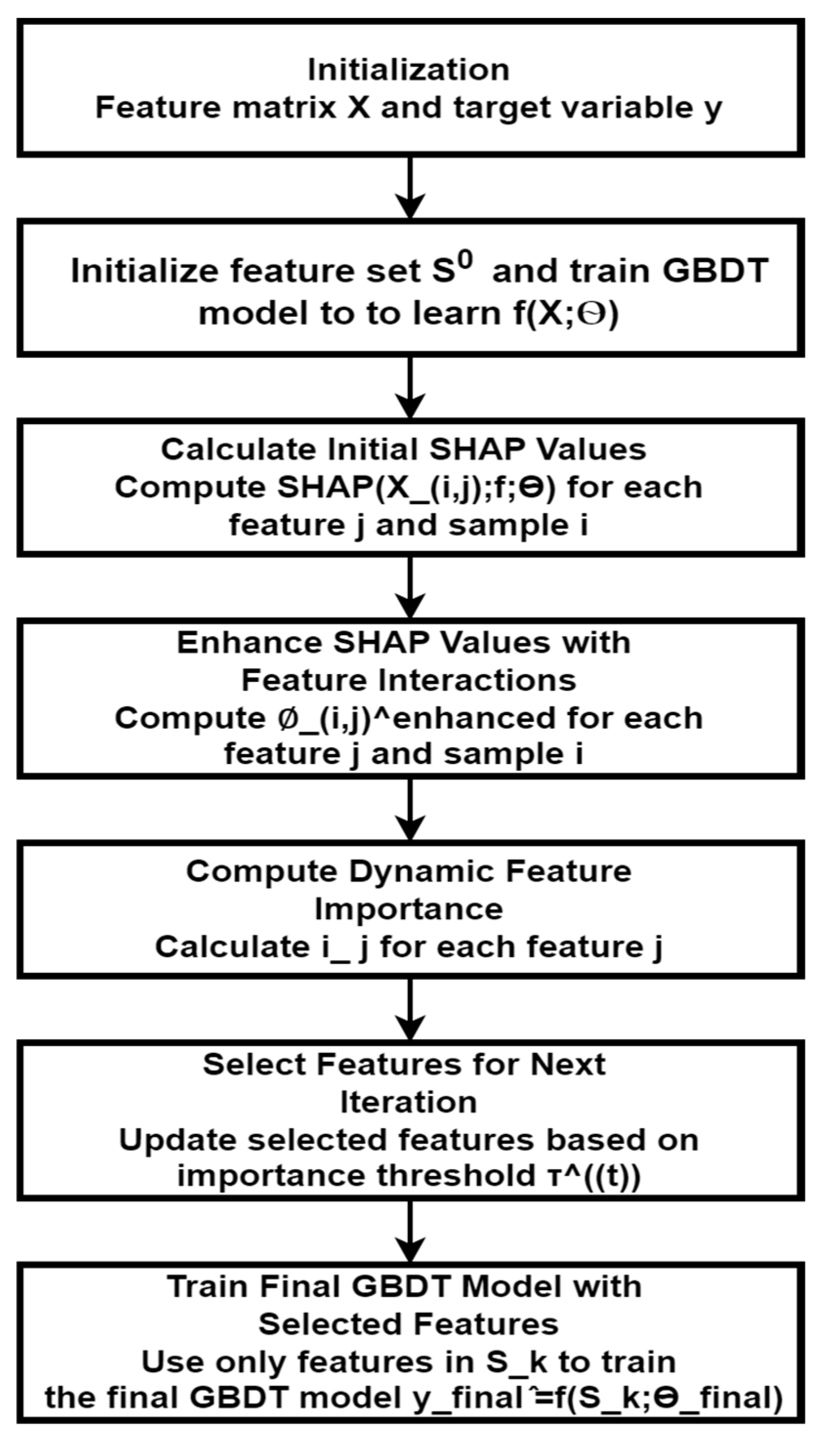
The significance of every attribute is calculated consistently and is ranked according to their Shapley rate in a predetermined arrangement. The model is subsequently trained to utilize the most significant attribute, as demonstrated in the subsequent iterations, starting from the top and progressing until the most favorable attribute subset is recognized.
1st interaction: =
2nd interaction: =
3rd interaction: = ,
Ultimately, the objective problem can be effectively modeled by identifying and utilizing the optimal feature subset.
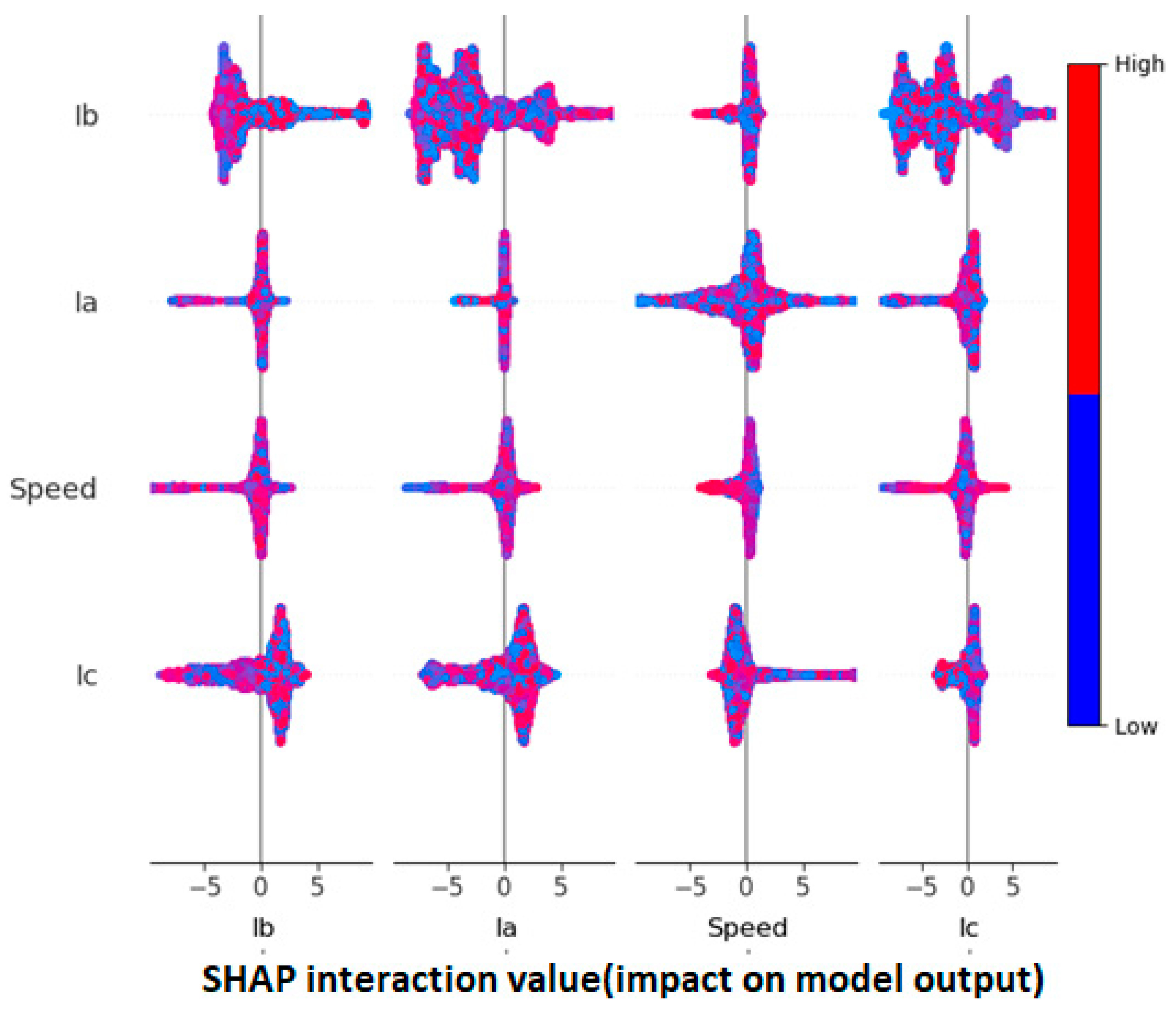
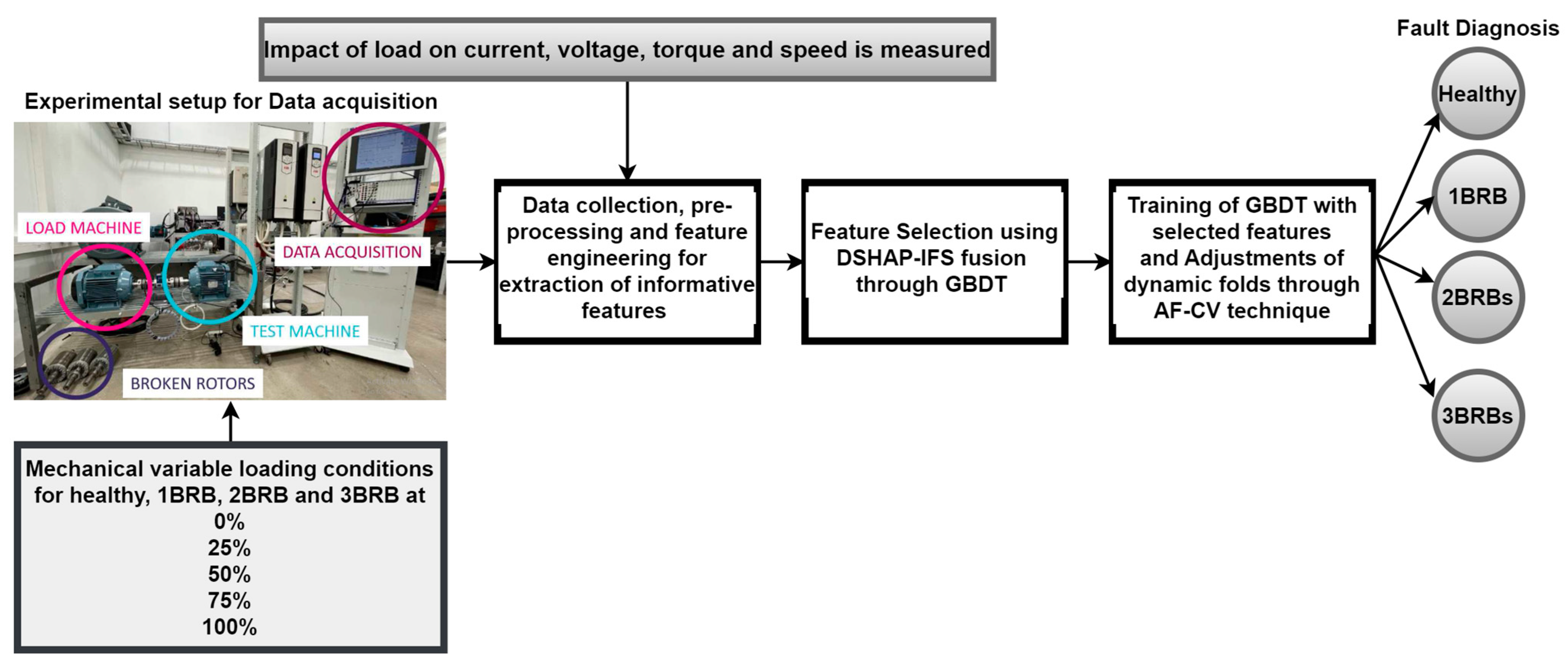
In this paper, dynamic SHAP interaction feature selection (DSHAP-IFS) with gradient-boosted decision trees (GBDT) is introduced—an innovative technique for feature selection by exploiting interactions among features to improve the model performance. Like a house built on the foundation of GBDT, DSHAP-IFS increases the importance of feature selection and contributes insight into the importance of the feature in the dataset. Through the iterative refinement of feature selection, by dynamically augmenting SHAP values, DSHAP-IFS can capture the subtle correlations among features, enabling further enhancement of model interpretability and predictive performance. This methodology helps identify the critical features that make a model work so that the learned model can be applied more rigorously to predict output for a variety of different applications. The main objectives and contributions of this article are given below:
Introduction of a sophisticated method leveraging SHAP-fusion GBDT for precise detection and classification of BRBs in DTC-controlled induction motors.
Application of extensive feature engineering and SHAP-based feature selection to extract informative features from electrical signals (current, voltage, torque, speed) and motor characteristics.
Explore the impact of SHAP-based feature selection on model interpretability and understanding of the underlying mechanisms driving BRB detection and classification in DTC-controlled induction motors.
To ensure that the proposed method performs reliably under diverse loading conditions (0%, 25%, 50%, 75%, and 100%) and attains a high accuracy rate (99%) in the detection and classification of broken rotor bars.
Application of adaptive fold cross-validation to reduce the overfitting in which the number of folds is changed during the optimization process.
Demonstration of consistent and reliable classification performance of the GBDT classifier under varying loading conditions, ensuring accurate detection and classification of BRBs across different operational scenarios.
Significance in advancing the field of machine learning for motor anomaly detection by achieving an impressive accuracy rate of 99% for all loading conditions, thereby contributing to the development of preventative maintenance strategies and enhancing the dependability of DTC-controlled induction motors.
8. Results and Discussion
Figure 6,
Figure 7,
Figure 8 and
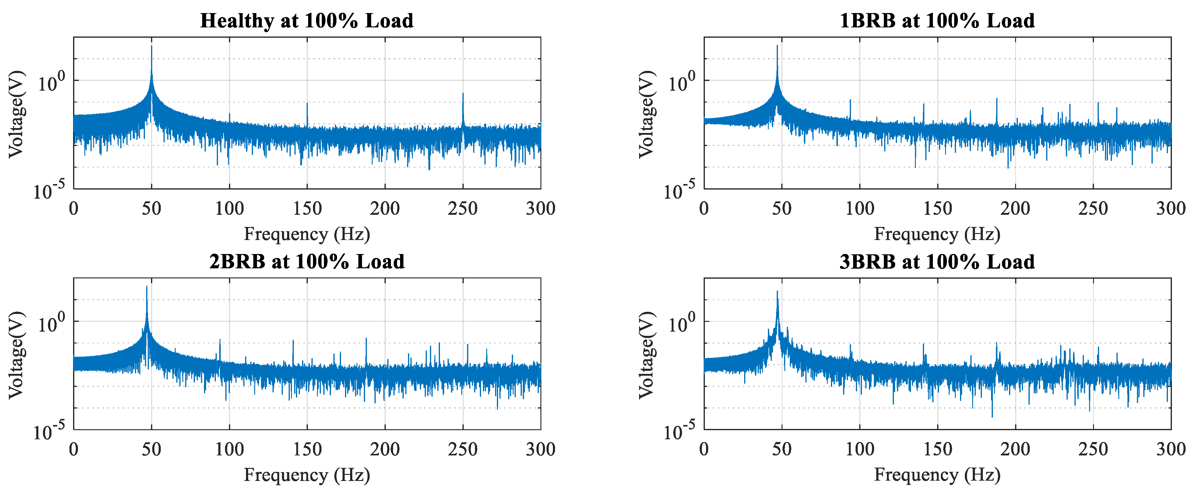
Figure 9 represent the frequency spectrum of the motor’s current, voltage, speed, and torque underdifferent loading circumstances. As the system load progressively rises from 0% to 100%, many parameters, including current, voltage, torque, and speed, undergo alterations in their spectral characteristics. These changes are evident as a rise in the occurrence of harmonics surrounding the primary frequency component, usually seen at about 50 Hz in the current and voltage signal spectrum. More specifically, these harmonics represent sidebands known as the left-side band (LSB) and right-side band (LSB) around the center frequency. The left-side band is the lower frequency, and the right-side band is the higher frequency. The appearance and strengthening of these harmonics in the signal spectrum demonstrate the impact of load variation on the electrical system, which is of great importance for understanding the system’s behavior and performance in different operating conditions. The fast Fourier transform (FFT) analysis of current, voltage, speed, and torque signals for different conditions (healthy, 100% load, 1 BRB, 2 BRB, and 3 BRB phase unbalance) is an indispensable tool to investigate the operating performance and fault conditions of induction motors. Whenever the motor is healthy and operating at full load, the FFT will also show the highest frequency components for the normal motor mode of operation. Introducing one broken rotor bar (BRB) results in additional frequency components indicative of the fault, with further changes observed in the presence of two or three broken rotor bars. By comparing the FFT results across different conditions, characteristic frequency signatures of rotor bar faults emerge, enabling effective diagnosis and assessment of fault severity in induction motors, thereby facilitating condition monitoring and maintenance strategies for optimal motor performance and reliability. In the context of induction motor operation, as the load increases from 0% to 100%, the amplitude of harmonics around the fundamental component tends to increase. The fundamental component, typically appearing at 50Hz in power systems operating at 50 Hz, represents the primary frequency associated with the motor’s rotational speed. This phenomenon can be attributed to the non-linear behavior of the motor under varying load conditions, which leads to the generation of additional harmonics in the current, voltage, speed, and torque signals. As the load increases, the motor experiences greater magnetic flux variations and saturation effects, resulting in non-sinusoidal waveforms with enhanced harmonic content. This observation is consistent with the principles of electrical machinery and power system analysis, where load variations impact the spectral characteristics of motor signals due to changes in operating conditions and system dynamics. Such findings contribute to the academic understanding of motor behavior and provide insights into the effects of load variations on harmonic distortion in induction motors, offering implications for motor performance assessment and condition monitoring strategies in practical applications.
Figure 7,
Figure 8,
Figure 9 and
Figure 10 illustrate the frequency domain analysis of current, voltage, torque, and speed signals for healthy, 1 BRB, 2 BRB, and 3 BRB at different full-load scenarios.
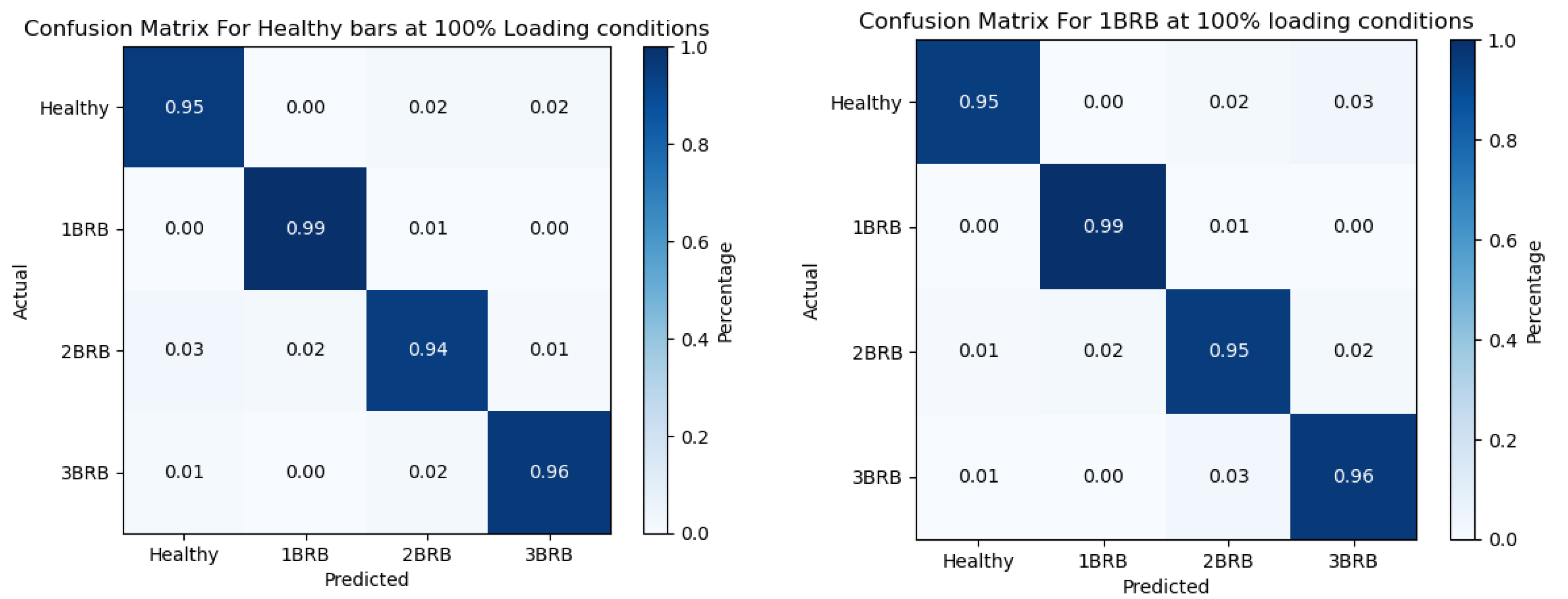
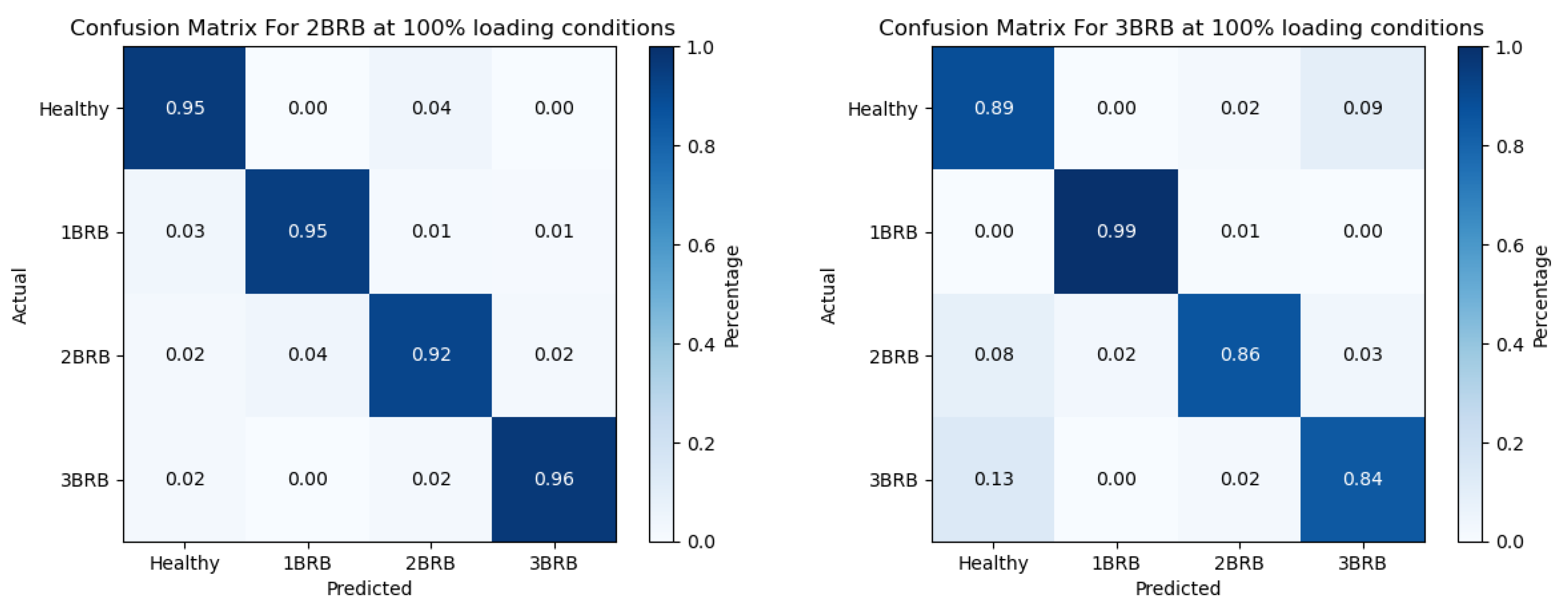
The confusion matrix illustrates the classification performance of a machine learning model in distinguishing between healthy and faulty rotor bar conditions in induction motors operating at 100% load. Therefore, a properly functioning and robust system would be the most precise, as it correctly identified the highest percentage of healthy rotor bars as healthy. The classification accuracy diminishes as the fault severity escalates from 1 BRB to 2 BRB and 3 BRB, indicating greater difficulty in determining the presence and kind of rotor bar faults. The expected performance of the model can be assessed using the confusion matrix, which provides a concise overview of the true positive, true negative, false positive, and false negative classifications of rotor bar circumstances. An in-depth analysis of the confusion matrix will be conducted to gain a comprehensive understanding of the model’s ability to detect and categorize various fault scenarios. This analysis aims to improve fault diagnosis and condition monitoring strategies for induction motors operating under diverse load conditions.
Figure 11 shows the confusion matrix analysis for a healthy state and faulty states (1 BRB, 2 BRBs, and 3 BRBs) at 100% loading circumstances.
A ROC curve describes the classification model’s ability to differentiate between normal and defective rotor bar conditions in induction motors. The curves are presented for three fault levels: 1 BRB, 2 BRB, and 3 BRB. A receiver operating characteristic (ROC) curve illustrates the relationship between the sensitivity (true positive rate) and the specificity (1—false positive rate) of a classification model when the threshold for classifying data points varies. The ROC curves in this study assess the model’s capacity to correctly identify true-positive cases while minimizing false-positive detections across various fault scenarios. An ideal classification model will have an ROC curve that roughly aligns with the upper-left corner of the plot, indicating a high level of sensitivity and a low rate of false positives. By analyzing the ROC curves of healthy and faulty rotor bars, we may obtain vital information about the model’s capacity to effectively identify rotor bar faults of different levels of severity in various operating settings.
Figure 12 shows the receiver operating characteristic curves for a healthy state: 1 BRB, 2BR, and 3 BRB at 100% loading conditions.
Table 5,
Table 6,
Table 7 and
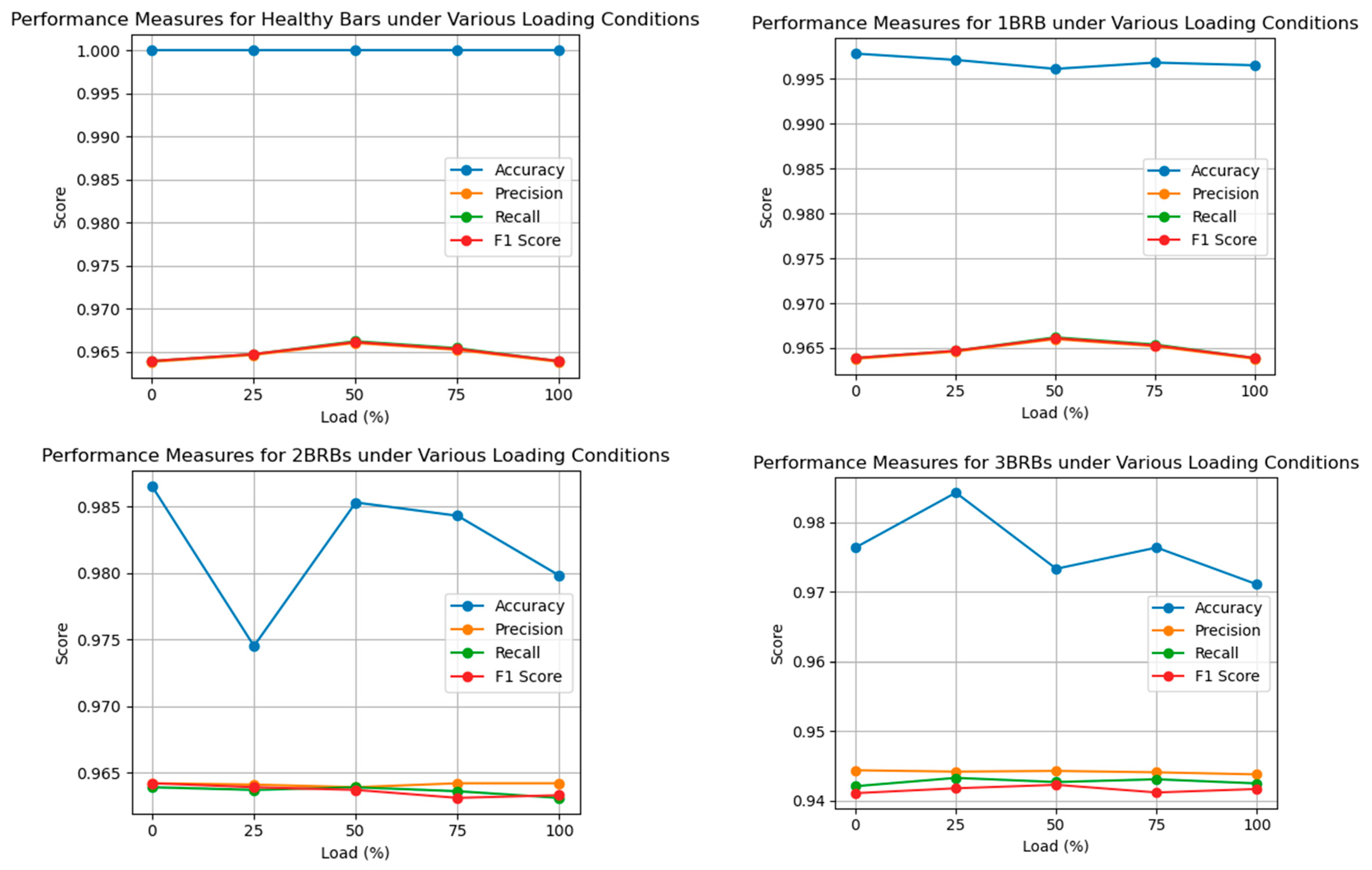
Table 8 demonstrate the performance metrics for the intact rotor bars and various fault scenarios (1 BRB, 2 BRBs, and 3 BRBs) when the induction motor operates at different load levels ranging from 0% to 100%. The tables collectively illustrate the classification model’s performance metrics—accuracy, precision, recall, and F1 score—under various loading conditions for healthy rotor bars and rotor bars with one, two, and three broken bars (1 BRB, 2 BRBs, and 3 BRBs). For healthy rotor bars, the model demonstrates exceptional performance, achieving perfect accuracy and high precision, recall, and F1 scores across all load levels. The consistent achievement of performance measures with accuracy levels exceeding 99% for healthy rotor bars signifies that the model possesses the capability to accurately and precisely classify these bars amidst varying loads. Specifically, the accuracy falls a bit when looking at the 1 BRB conditions, but the precision, recall, and F1 scores are consistent and high, showing the model is working relatively well. Weight fall of the fault impact increases to 2 BRBs, down accuracy to 2 BRBs, and the minimized precision, recall, and F1 scores alsoshowthat the difficulty of fault detection rises from healthy to faulty conditions. For 4BRBs, the performance of the proposed model drops significantly due to even lower precision, recall, and F1 scores as well as reduced accuracy compared to 3 BRBs, indicating that this model faces more difficulties in identifying and classifying severe faults under stress conditions. These requirements highlight the importance of developing powerful algorithms that not only work effectively for a wide range of fault scenarios but also ensure that high performance is maintained, hence enabling good fault diagnostics and condition monitoring in real industrial machinery. We employ these tables to assess the performance of powerful fault-tracing algorithms on real industrial machinery. Makarov and Goresky highlight the importance of operational conditions and fault severity in the establishment of successful fault diagnosis and condition monitoring schemes.
The performance measures during the detection and classification of 3 BRBs (broken rotor bars) in direct torque-controlled (DTC) induction motors under different loading conditions are illustrated in
Figure 13. The rows correspond to a percentage of load from 0% to 100%. Accuracy, precision, recall, and F1 score: These are the metrics that will be used to calculate the performance of the classification model. 0% load: It means that the model indicates the actual condition 98.64% of the time, whetherthe part is healthy or faulty. Consequently, we have obtained high test accuracy, e.g., precision, recall, and F1 score metrics show consistent performance, ranging from 94.11% to 94.38%. In general, the results presented show that the approach using dynamic SHAP feature selection with GBDT can decently identify cracked rotor bars in DTC induction motors at different load conditions. The high accuracy, precision, recall, and F1 score metrics highlight the reliability of the classification model, enlarging itsin predicting maintenance and fault prevention of industrial drive systems.

