Article

A Comparative Study of Pole–Slot Combination with Fractional Slot Concentrated Winding in Outer Rotor Permanent Magnet Synchronous Generator for Hybrid Drone System

Department of Electrical Engineering, Hanyang University, Seoul 04763, Republic of Korea
*
Author to whom correspondence should be addressed.
Machines 2024, 12(7), 464; https://doi.org/10.3390/machines12070464
Submission received: 1 June 2024 / Revised: 8 July 2024 / Accepted: 8 July 2024 / Published: 10 July 2024
(This article belongs to the Section Electrical Machines and Drives)

Abstract

:
This paper is a comparative study of pole–slot combinations with fractional slot concentrated windings in an outer rotor permanent magnet synchronous generator (ORPMSG) for a hybrid drone system. Fractional slot machines have been studied for automotive applications because of their high performance and simple winding manufacturing, compared with those of integer slot machines. In this study, four pole–slot combinations of ORPMSG with fractional slot concentrated windings were selected for comparison with the performance of the hybrid drone system. Based on the results of a finite element analysis (FEA), the machines were analyzed for cogging torque, back electromagnetic force (BEMF), torque, and electromagnetic loss under the same conditions as the machine specifications. Among the four pole–slot combinations of the ORPMSM, a one pole–slot model of the ORPMSG was selected, considering the performances of the machines. The selected pole–slot model of the ORPMSG was manufactured, and experiments were conducted on the manufactured model to verify the FEA results. Finally, the effectiveness of the comparative study of pole–slot combination with fractional slot concentrated winding in ORPMSM was verified by comparing the FEA and experimental results.

1. Introduction

Recently, with technological developments related to unmanned aerial mobility (UAM), the applications of drones have been rapidly expanding in various fields, including military, logistics transportation, medicine, agriculture fields, and disaster observation [1,2,3,4,5,6]. The World Economic Forum (WEF) designated it as the representative field that led to the fourth industrial revolution. Drones are a complex industry that combines cutting-edge technologies such as aviation, Information and Communications Technology (ICT), and Sofeware (SW), and they have growth potential in production and operation [7,8]. Accordingly, research on drone technology has received significant attention, both domestically and abroad [9].
Because the flight time of a drone system is limited by its fuel or battery, the most challenging issue in drone systems is the high energy density of the propulsion system [10,11]. Hybrid drone systems have been studied to achieve propulsion systems with high energy densities. Figure 1 shows a hybrid drone system. A conventional hybrid drone system comprises a battery, engine, fuel pack, motor, and drive as shown in Figure 1a [12]. Due to limited fuel and battery, drone systems generally have a flight time of approximately 30 min. If the continuous operation of a drone system is required, it must be fueled or have its battery charged during its flight [13,14,15]. To address these shortcomings, several studies have addressed increasing energy density and improving flight time. Hybrid engine–generator drone systems have received significant attention in several studies [16,17,18,19].
Figure 1b shows the hybrid engine–generator system. Compared with a conventional drone system, the hybrid drone system includes the hybrid engine–generator system with a permanent magnet synchronous generator (PMSG). When the drone system is propelled by a motor, the PMSG generates electrical energy from the engine, which charges the battery of the hybrid drone system. Although the overall weight of the hybrid drone system increases as the PMSG is increased, the flight time can increase because the PMSG supplies electrical energy to the battery. Therefore, in the hybrid drone system with the engine–generator, the efficiency of the PMSG is important for improving the flight time [20,21].
Since the drone system operates in the sky, a highly reliable system is required [22,23]. Therefore, a stable power supply is necessary under all conditions. PMSG is required in hybrid drone systems to minimize total harmonic distortion (THD) of the back electromagnetic force (BEMF) and the cogging torque because of the inherent pulsation, vibration, noise, and high-quality electric energy. These issues can be resolved by using a fractional slot concentrate winding (FSCW). FSCWs are excellent at reducing harmonics and have a low cogging torque. Furthermore, they have excellent manufacturability, and high efficiency and high torque density, due to their short end coils [24,25].
Several studies have been conducted to investigate the benefits and limitations of different FSCW machines [26,27,28,29]. In [26], the characteristics of pole–slot combination in electrical machine are analyzed based on the Star of slots. Since it does not take into account the spatial harmonics by slot, the nonlinear characteristics by magnetic saturation, and the flux leakage characteristics of the electrical machine, the comparison study according to pole–slot combinations should be conducted using FEA. In [27], a design of an FSCW generator for low cogging torque is studied. In this research, a comparative study of pole–slot combinations of FSCW generators was performed based on the analytical method. However, high-accuracy comparisons were not conducted based on FEA to consider the magnetic saturation and the magnetic flux leakage. In [28] and [29], a comparison study was conducted based on FEA for highly reliable characteristics according to the pole–slot combination of an FSCW permanent magnet synchronous motor. Although there are comparative studies according to the pole–slot combinations, no studies have been conducted comparing the ORPMSG or THD of the BEMF. In this paper, we extend this and perform a comparative analysis of various FSCW pole–slot combinations in ORPMSG. Through this, an excellent pole–slot combination is derived for drone generators, and the reliability of the analysis results is verified through the manufacture and testing of a prototype.
In this paper, the characteristics of pole–slot combinations with fractional slot concentrated winding in an outer rotor permanent magnet synchronous generator (ORPMSG) were investigated for a hybrid drone system. Four pole–slot combinations were selected to compare characteristics such as the BEMF, cogging torque, torque ripple, and efficiency. Under the same PM material, core material, and slot area conditions, the pole–slot combination models were analyzed using finite element analysis (FEA) in ANSYS Maxwell. Based on the analysis results, the optimal pole–slot combination was selected. Furthermore, the selected pole–slot combination model was manufactured, and an experiment was performed to verify the characteristics of the ORPMSG. Finally, the effectiveness of the comparison with pole–slot combination models was verified.
This paper is organized as follows. In Section 2, the basic principles and equivalent circuit of the ORPMSG are discussed. In Section 3, the characteristics of the pole–slot combination models are discussed using FEA. In Section 4, a comparison between the FEA and prototype experiment is discussed. Finally, the conclusions are presented in Section 5.

2. Principle and Equivalent Circuit of PMSG

The permanent magnet synchronous motor and generator exhibit inverse input and output correlations. When mechanical power causes the rotor of a PMSG to rotate, the magnetic flux from the permanent magnets induces a no-load voltage (back electromotive force, BEMF) in the armature coil. When a load is connected to the stator, an electric current passes through the winding and a voltage is induced due to the armature reaction [30,31]. The voltage induced by the armature reaction is expressed as follows:
e a = d λ a d t = L a d i a d t
where ea is induced voltage by the armature reaction, λa is the armature reaction flux linkage, La is the phase inductance, and ia is the phase current. Equation (1) can be expressed in the frequency domain as follows:
E a = j X a I a
where Xa is the armature reaction reactance. If a leakage flux exists in the PMSG, the induced voltage by leakage flux linkage can be expressed as follows:
E l = j X l I a
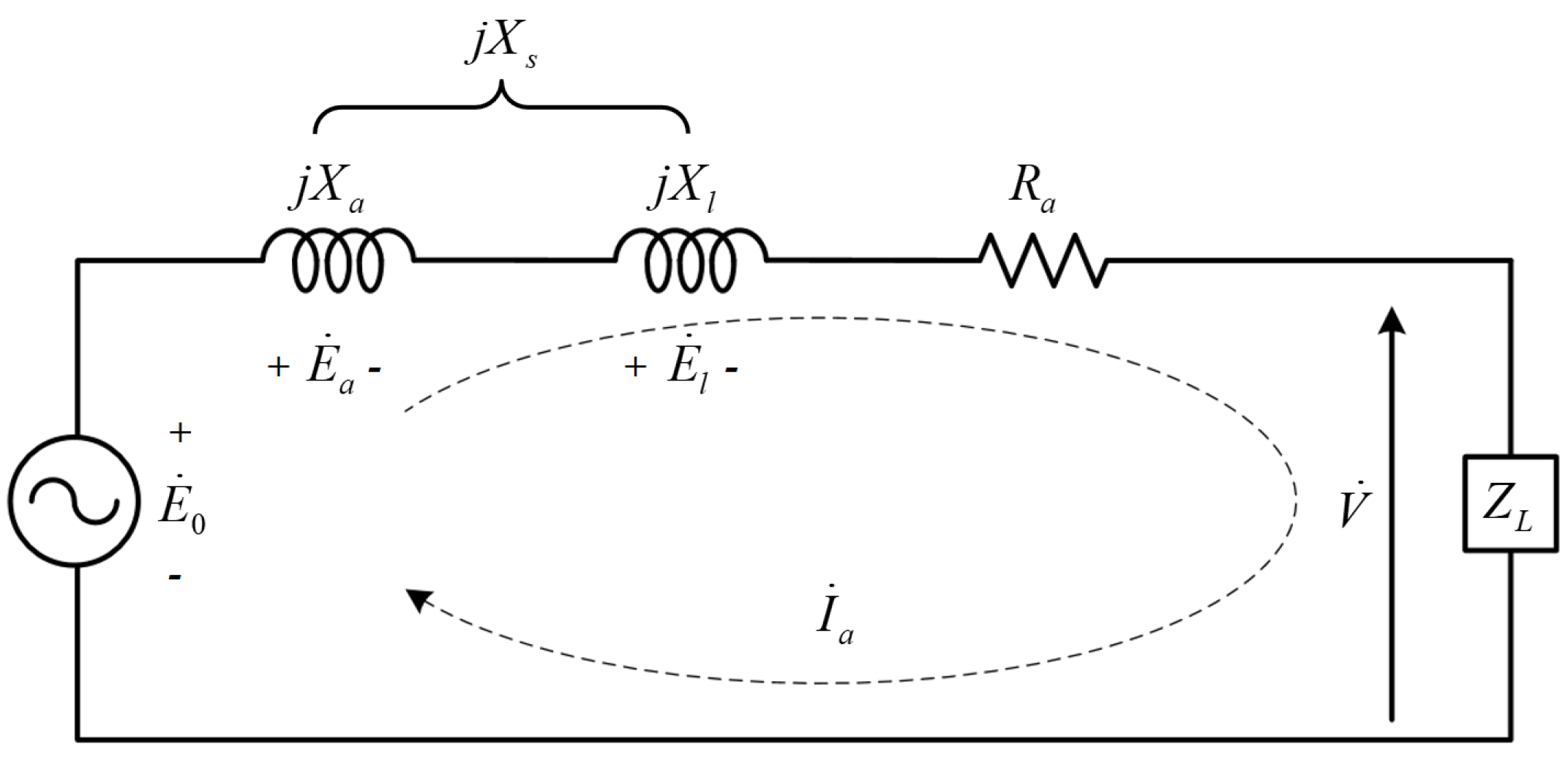
where Xl is the leakage reactance. Considering the phase resistance, armature reaction reactance, and leakage reactance, the equivalent circuit for a single phase of the PMSG is shown in Figure 2. From Figure 2, the voltage equation of the PMSG is expressed as follows:
V = E 0 R a I a j X s I a
where V is the output voltage, E0 is the BEMF, Ra is the phase resistance of the armature, and Xs is the synchronous reactance which is the sum of the armature and leakage reactances. The output voltage of the PMSG is obtained by subtracting the voltage drops in the synchronous reactance and resistance from the BEMF. If the PMSG rotates with mechanical power and the load is connected to the PMSG, a magnetic torque is generated in the direction opposite to the rotational direction of the mechanical power. Therefore, mechanical power is required to overcome the torque in PMSG. Equation (5) expresses the output power based on the energy conversion.
P e = T G ω s P l o s s = V I a cos θ
where Pe is the output power, TG is the mechanical torque by the engine, ωs is the rotational speed, Ploss is the loss of the PMSG, and θ is the angle of the power factor. From Equation (5), the required torque of the PMSG can be expressed as follows:
T G = V I a cos θ + P l o s s ω s
From Equation (6), the torque is determined by the output voltage. Furthermore, because the output voltage is determined by the BEMF, the harmonic component of the BEMF is an important component of the PMSG. In a hybrid drone system, the PMSG is derived from engine and battery charging. Therefore, the PMSG has a low cogging torque and total harmonic distortion (THD) of the BEMF for reliable or hybrid drone systems. In this paper, the cogging torque and THD of the BEMF in the PMSG are analyzed according to a pole–slot combination based on FEA as in Section 3.

3. Comparison of ORPMSG Models

3.1. Constraints of Comparison Models

Analytical models are used to compare the features of the pole–slot combinations under identical conditions, taking into account the constraints. Table 1 shows the constraints on the analysis models. The characteristics of the pole–slot combinations are analyzed under the same conditions of motor size, total slot area, total volume of the PM, slot opening, and pole arc ratio. The generator used in this paper requires an output of more than 1 kW at 2000 rpm. Since the generator charges a battery of 48 Vdc at 5000 rpm, the line to line voltage of the generator at 5000 rpm is greater than 57 V. In Section 3.2, the pole–slot combination models under the conditions as shown in Table 1 are discussed. The rotor and stator core in this paper use lamination electrical steel such as 50PN470 in POSCO which is widely used in the industry [32,33].

3.2. Comparison Models of Pole–Slot Combinations for ORPMSG

The generator in the hybrid drone system requires a low cogging torque and total harmonic distortion (THD) of the BEMF. In PMSG, the cogging torque and THD of the BEMF are determined by the pole–slot combination [34]. When the pole–slot combination is selected, we consider the following:
  • The larger the winding coefficient, the higher the BEMF and torque generated.
  • The least common multiple (LCM) of the poles and slots is proportional to the cogging torque frequency. In general, the frequency of the cogging torque can increase, and the magnitude of the cogging torque can reduce as the LCM increases.
  • Fractional slot machines contain fewer harmonics than do integer slot machines [34].
  • The motor periodicity is defined as the greatest common divisor (GCD) of the pole pairs and slots. The symmetry of the magnetic flux density is determined by the GCD, which is the motor periodicity [35,36].
Considering the characteristics of pole–slot combination, we select four pole–slot combinations: 10P12S(M1), 14P12S(M2), 14P18S(M3), and 16P18S(M4). Table 2 shows a comparison of selected pole–slot combinations, and Figure 3 shows the structures of the selected pole–slot combinations. In Section 4, the characteristics of the pole–slot combinations under the conditions shown in Table 1 are compared.

4. Comparison of the Characteristics of the Pole–Slot Combination

In Section 3, the electromagnetic characteristics of the four selected pole–slot combinations are compared using FEA in ANSYS Maxwell 2021R1. In Section 4.1, open circuit characteristics including the cogging torque and THD of BEMF are analyzed. In Section 4.2, the load characteristics are compared when a sinusoidal current is applied to the ORPMSG, and an external circuit analysis is performed to compare the generator characteristics according to the resistance load.

4.1. No-Load Characteristic

4.1.1. Airgap Magnetic Flux Density

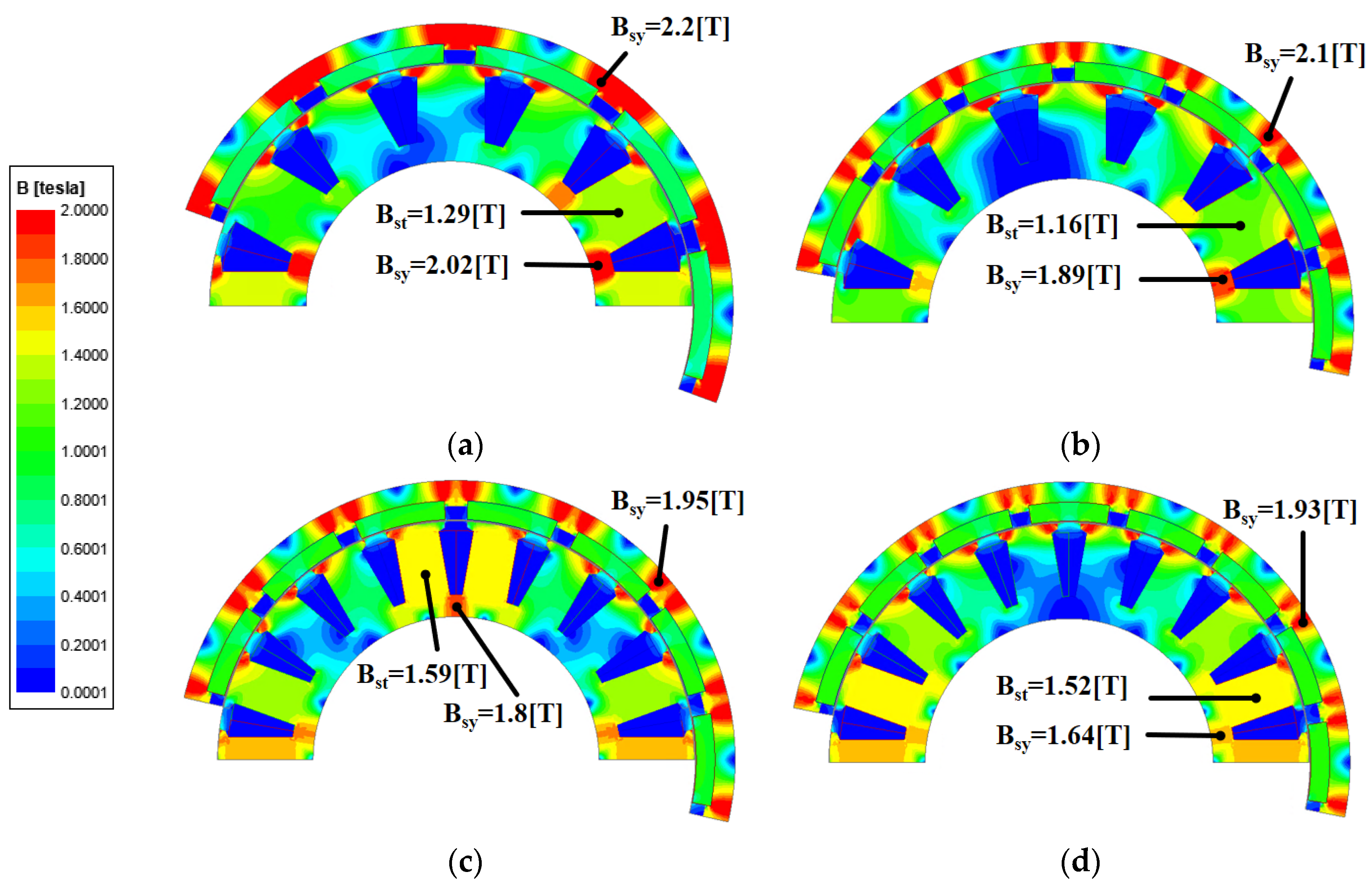
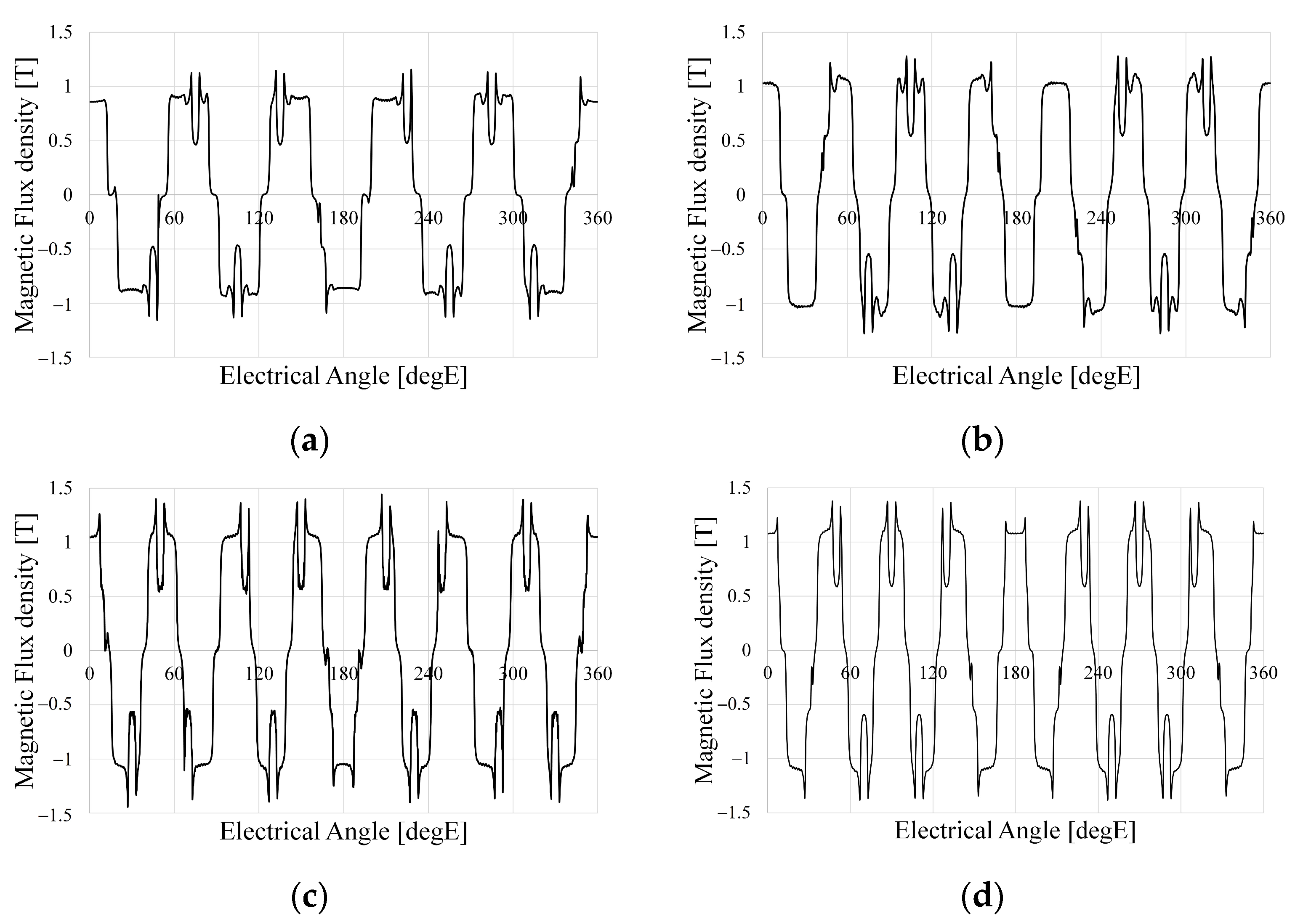
The harmonic components of the magnetic flux density in the airgap are related to the flux linkage and can have significant negative effects on the harmonics of the BEMF, power, vibration, and noise. Figure 4 shows the distribution of the magnetic flux density according to the pole–slot combination. Figure 4 shows that each model is designed so that the teeth and yoke are saturated at 1.5 to 2.2 T considering the magnetic saturation. Figure 5 shows the airgap magnetic flux density based on the pole–slot combinations. As the number of poles increases, the waveform of the airgap magnetic flux density becomes more sinusoidal due to the increased leakage magnetic flux density. Furthermore, the magnitude of the airgap magnetic flux density decreases with the slot opening as the magnetic reluctance increases. Figure 6 shows the fast Fourier transformation (FFT) results of the airgap magnetic flux density according to the pole–slot combinations. From Figure 6, the fundamental frequency is decided by the number of pole pairs. Since the pole–slot combinations are fractional slots with a concentrated winding, there is a subharmonic component whose frequency is lower than the fundamental frequency. The subharmonic component of M2 is higher than those of the other models. Excluding the fundamental harmonic and subharmonic components, the harmonic components are caused by the permanent magnet and slot. Because the pole arc ratio and slot opening are the same, the harmonic components of the permanent magnet and slot are similar.

4.1.2. Cogging Torque

The cogging torque is the reluctance torque that aligns the magnetic flux of the permanent magnet and the tooth structure, and it is expressed as follows [37]:
T c o g ( α ) = π L s t k 4 μ 0 ( R 2 2 R 1 2 ) n = 1 n N L G n N L B n N L sin ( n N L α )
where μ0 is the permeability in the air, NL is LCM(Ns,Np), Np and Ns are the number of poles and number of slots, respectively, R1, R2, and Lstk are the inner and outer diameters of the air gap and the stack length, respectively, α is the rotor position, and GnNL and BnNL are the Fourier coefficients of the airgap relative permeance and airgap flux density, respectively. From Equation (7), the period of the cogging torque is determined by the LCM of the pole and the slot number, and the cogging torque can be reduced as the period of the cogging torque is reduced. Since the mechanical frequency of the cogging torque is equal to the LCM of the numbers of poles and slots, the electrical period of the cogging torque is expressed as follows:
t c o g g i n g = 360 L C M ( N s , N p ) N p 2 [ degE ]
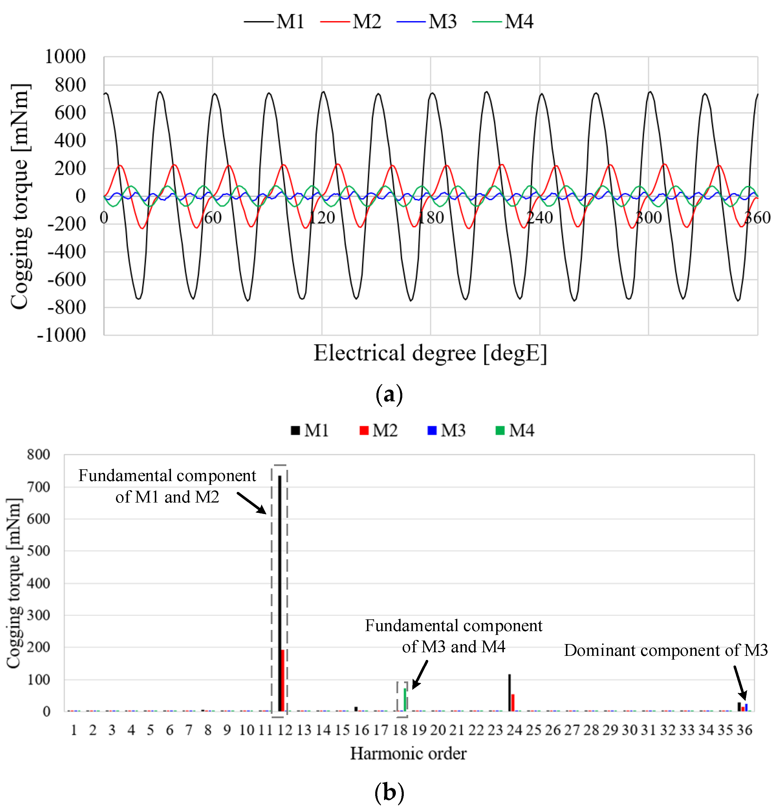
Table 3 shows the cogging torque characteristics of the pole–slot combination models. From Equation (8), the electrical period of the cogging torques of M1, M2, M3, and M4 are calculated as 30 degE, 30 degE, 20 degE, and 20 degE, respectively. Therefore, the fundamental harmonic orders of cogging torque of M1, M2, M3, and M4 are 12, 12, 18, and 18, respectively. The cogging torques of M3 and M4 are lower than those of M1 and M2 because the periods of the cogging torques are higher. Figure 7 shows the cogging torque waveform and FFT result of pole–slot combination models. The cogging torque of M3 is better than that of other models. The fundamental order of the cogging torque of M3 is 18 and the fundamental component of the cogging torque is near zero as shown in Figure 7b. The pole arc ratio and slot opening are affected by the cogging torque [38]. The cogging torque of M3 is optimized under the conditions of the slot opening and pole arc ratio as shown in Table 1. Since the slot opening and pole arc ratio are selected as constraints, the fundamental component of M3 is near zero. Consequently, the cogging torque of M3 is better than that of the other models.

4.1.3. Line to Line Voltage

From Equation (5), the harmonic component of the BEMF is an important performance factor because the torque ripple is determined by the voltage. Furthermore, the harmonic component of the BEMF is also important since the generator charges the battery. To compare the harmonic components of the pole–slot combinations, the THD of the BEMF is defined as follows:
T H D = h = 2 , 3 , V h 2 V 1 = V 2 V 1 2 V 1
where V1 is the fundamental component of the voltage, Vh is the nth harmonic component, and V is rms value of the voltage. From Equation (9), THD of the BEMF is the number of harmonics in the fundamental waveform. This implies that a large THD of the BEMF includes a high harmonics component of the voltage. Therefore, when designing a generator for charging the battery in the drone system, the pole–slot combination is an important design method by which to minimize the THD of the BEMF. Figure 8a shows the waveform of the line to line voltage and Figure 8b shows the FFT result of the line to line voltage. As shown in Figure 8a, the waveforms of M3 and M4 are more sinusoidal than are those of M1 and M2. The harmonic components of M3 and M4 are lower than are those of M1 and M2 as shown in Figure 8b. Table 4 shows the voltage characteristics of the analysis models. The line to line voltage of M3 is higher than those of the other models, and THD of M3 is lower than those of the other models as shown in Table 4.

4.2. On-Load Characteristic

4.2.1. Torque Characteristics by Sinusoidal Current

Because the torque ripple is related to the vibration and noise of the generator, it is an important characteristic that must be considered when designing a generator. The load characteristics are analyzed and compared with pole–slot combinations when an ideal sinusoidal current source is applied to the generator. In general, when a sinusoidal current is applied to a generator, its torque can be expressed as:
T e = e a i a + e b i b + e c i c ω m = 3 2 E 1 I m ω m + n   =   6   k 3 2 E n 1 + E n + 1 ω m I m cos ( n ω t + φ n )
where Te is the torque of the generator, ea, eb, and ec are each a phase BEMF of the generator, respectively, ia, ib, and ic are each a phase current of the generator, ωm is the rotational speed, E1 is the magnitude of the fundamental component of the BEMF, Im is the magnitude of the current, En−1 and En+1 are the (n − 1)th and (n + 1)th harmonic components of the BEMF, respectively, n is the harmonic order, and φn is the phase angle of the torque.
From Equation (10), the torque ripple is determined from the harmonic component of the BEMF. Because M3 and M4 are more sinusoidal than are M1 and M2 as shown in Figure 9, the torque ripples of M3 and M4 are lower than are M1 and M2. Figure 9 shows the torque characteristics of each model. Figure 9a shows the torque waveform of the torque. The average torque of M3 is higher than those of the other models, and the torque ripple of M3 is lower than those of the other models. Figure 9b shows the FFT results of the torque as shown in Figure 9a. As shown in Equations (7) and (10), the torque ripple has the harmonic component owing to the cogging torque and harmonics of the BEMF. In a fractional slot with a concentrated winding, the main torque ripple is determined by the cogging torque because the harmonic of the BEMF is lower. Table 5 shows the comparison with torque characteristics of each analysis model. The average torque of M3 is 6.25%, 4.31%, and 5% higher than those of M1, M2, and M4, respectively, and the torque ripples of M3 are 25.2%p, 8.6%p, and 1.8%p lower than those of M1, M2, and M4, respectively. Consequently, when the sinusoidal current source is applied to the generator, the torque characteristics of M3 are superior to those of the other models.

4.2.2. Generator Characteristic for External Resistance Load

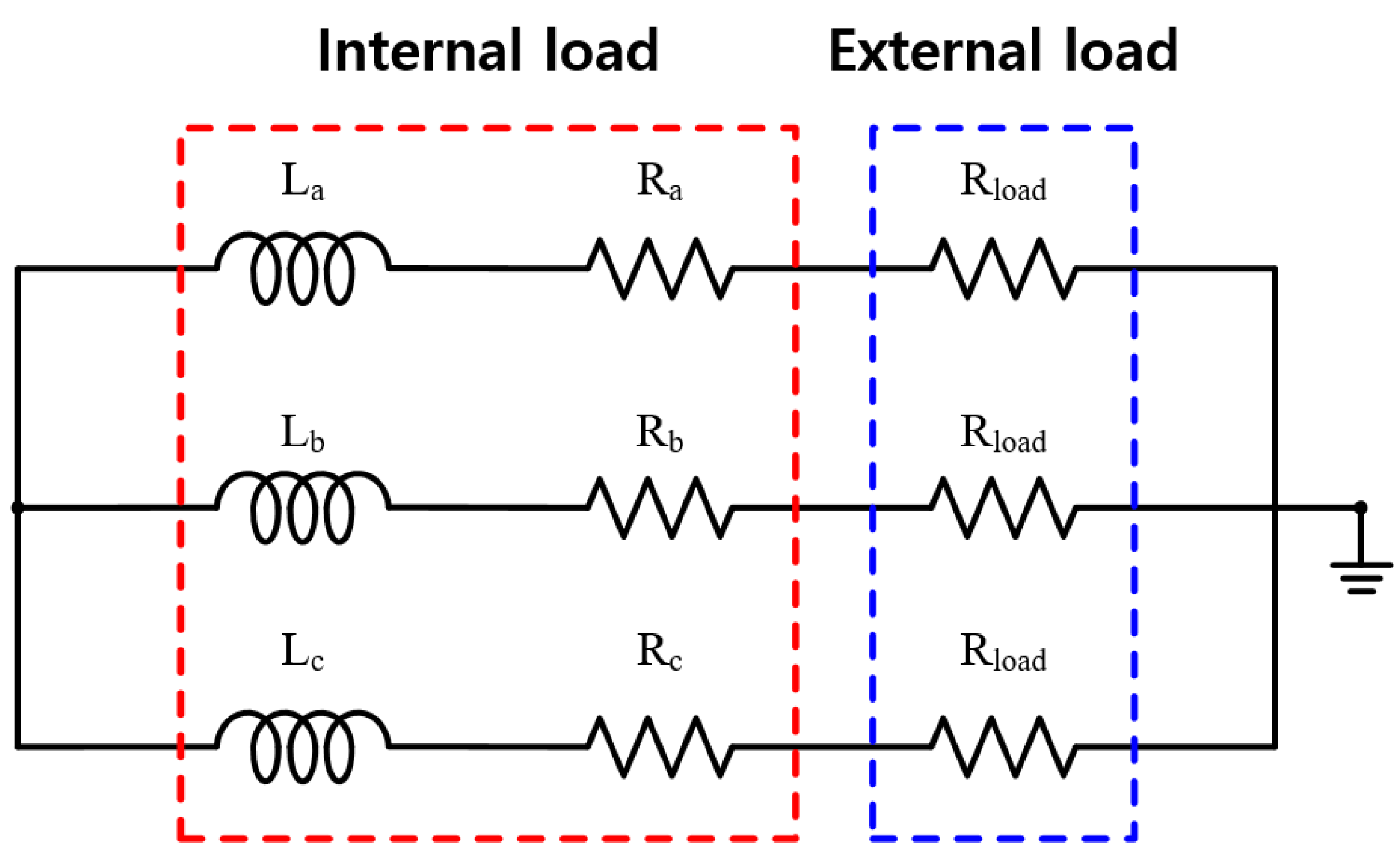
To compare the generator characteristics, the external load is accounted for by the resistance load as shown in Figure 10. When BEMF is generated by a mechanical input, the current flowing through the generator is determined by Ra and Rload. Figure 11 shows the comparison results of the generator characteristics for an external load when the generator speed is 2000 rpm. As shown in Figure 11a, because the output current is inversely proportional to the resistance, the output power of the generator increases as the resistance load decreases. The output power for the resistance load of M3 is higher than those of the other models because the BEMF of M3 is higher than those of the other models as shown in Figure 8a. Figure 11b shows the torque ripple of the generator under an external resistance load. The torque ripple of the generator for the external resistance load is determined by the cogging torque and THD of the BEMF as shown in Equations (6) and (9), respectively. As the cogging torque and THD of the BEMF of M3 are lower than those of the other models, the torque ripple of M3 is lower than those of the other models. Figure 11c–e show the PM eddy current loss, core loss, and copper loss, respectively. Since the PM eddy current loss and core loss are determined by the electrical frequency, they increase with the number of poles. Furthermore, as the end turn length decreases and the number of slots increases, the armature resistance decreases. Moreover, the copper loss of M4 is lower than those of the other models. As shown in Figure 11c–e, the main loss of the generator is the copper loss. Figure 11f shows the efficiency of the resistance load in the analysis models. The efficiency of M4 is higher than those of the other models because the copper loss of M4 is lower than those of the other models. Considering the torque ripple and efficiency of the generator, the pole–slot combination is selected as M3(14P18S).

5. Manufacture and Experiment Verification

5.1. Manufacture of Prototype and Experiment Environment

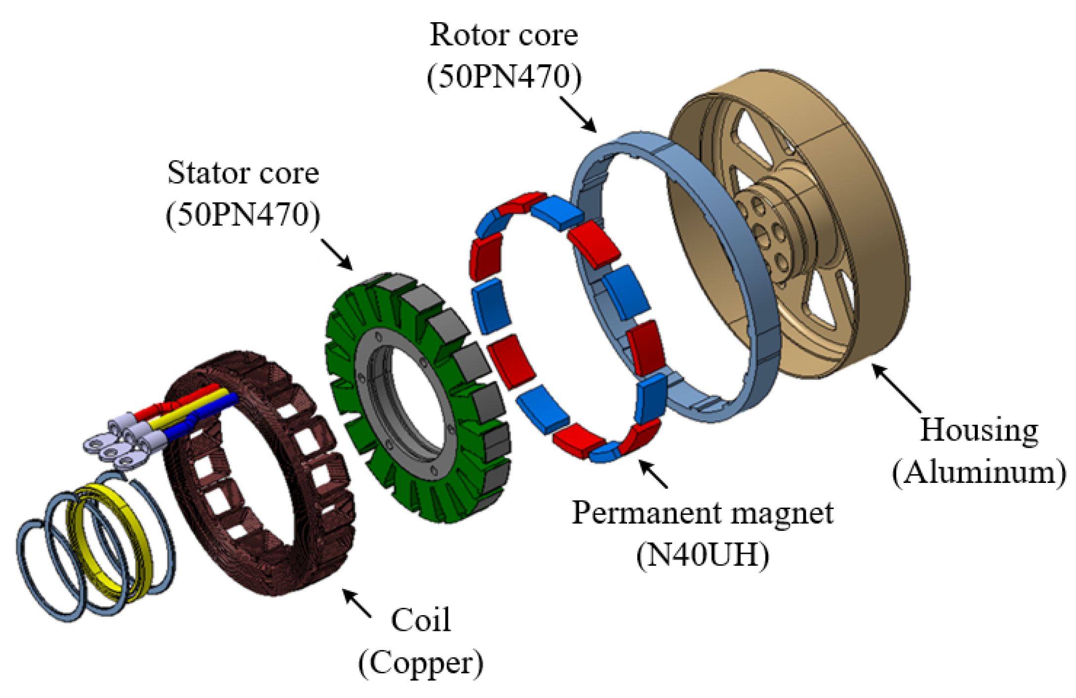
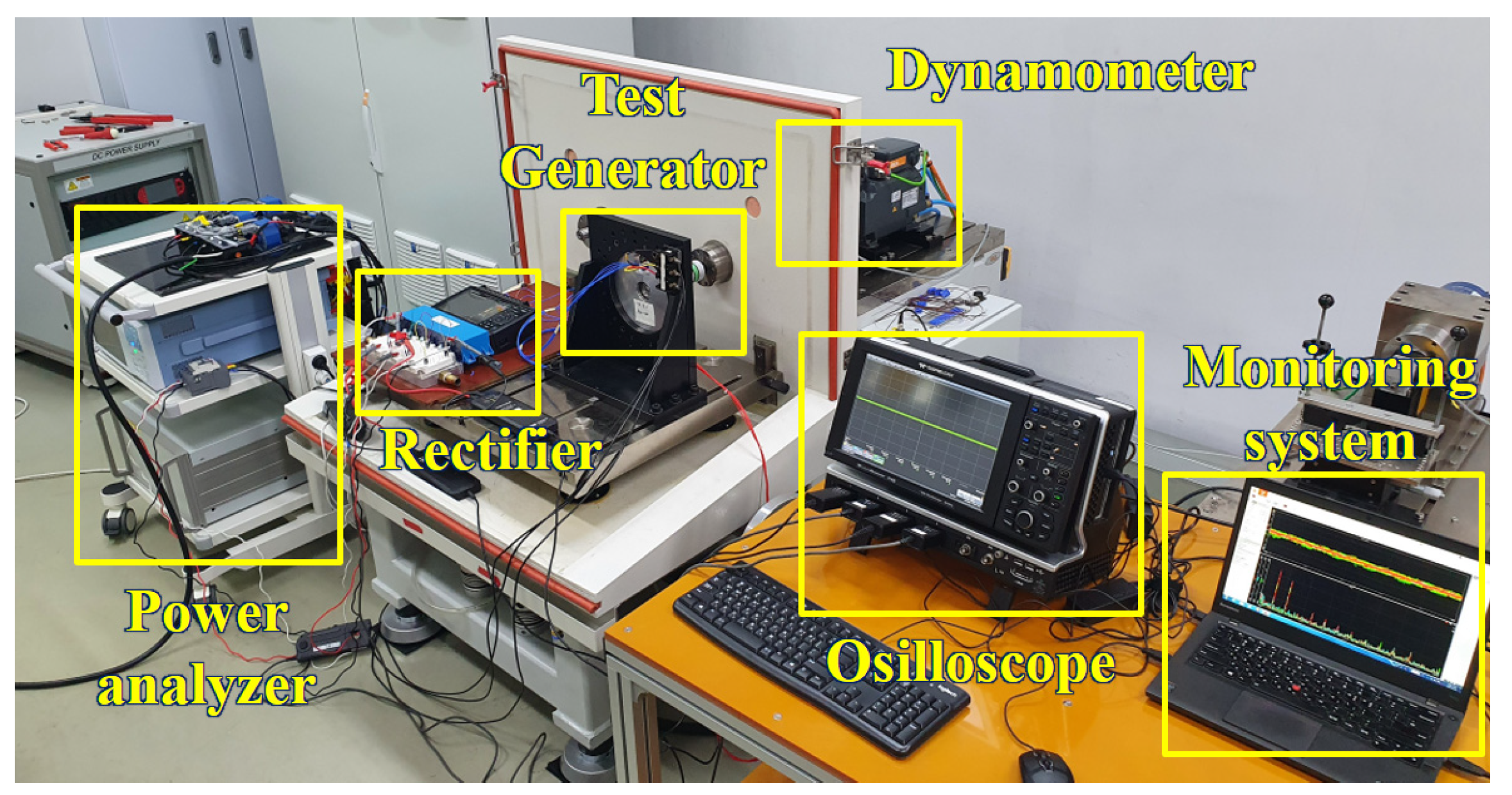
To verify the characteristics of the pole–slot combination, a prototype with a pole–slot combination of 14 poles and 18 slots is manufactured. Figure 12 shows the structure of the prototype. The stator and rotor core are laminated, and the magnetization of the permanent magnet is parallel direction. Figure 13a shows the stator, Figure 13b shows the stator with winding, Figure 13c shows the rotor, and Figure 13d shows the assembled generator. Figure 14 shows the experimental environment. The mechanical input power of the generator is received by the dynamometer, and the electrical output of the generator provides the load through the rectifier. In the power analyzer, the electrical power, efficiency, voltage, and current are analyzed, and the voltage and current waveforms are measured using an oscilloscope and monitoring system.

5.2. Performance Verification Comparison of FEA and Experimental Results

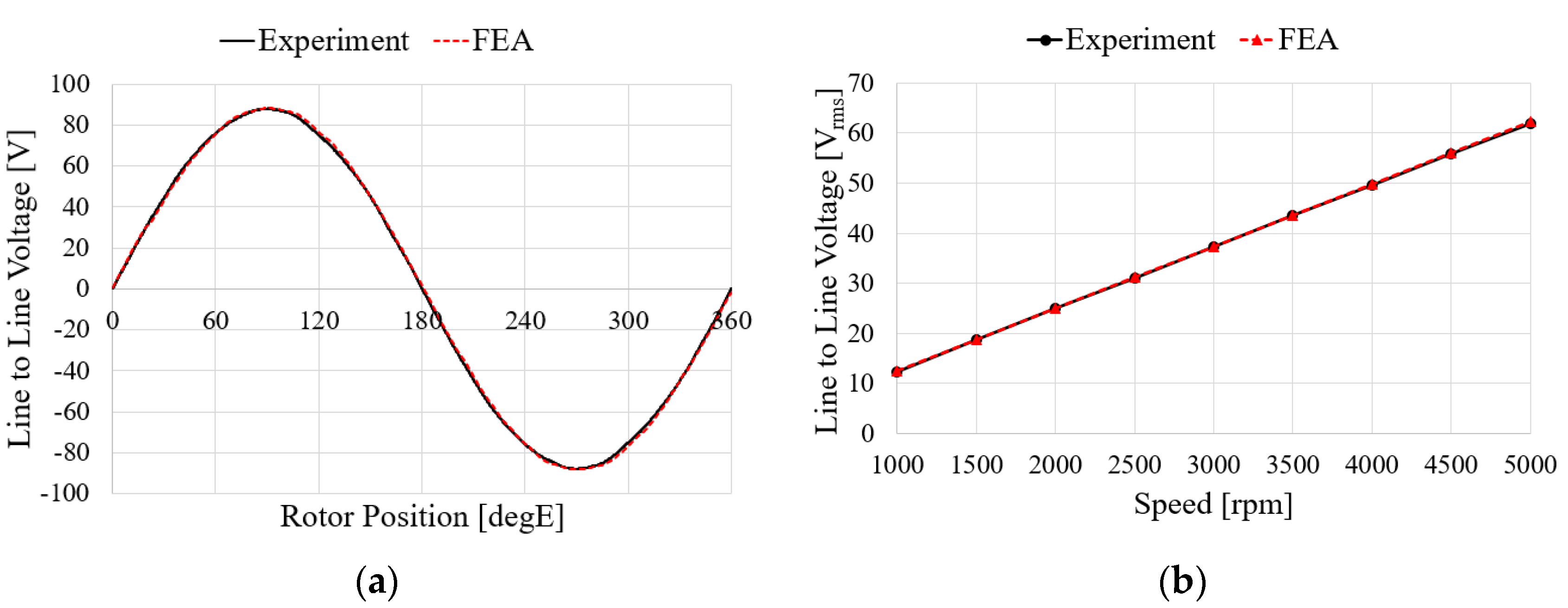
Figure 15 shows the characteristics of the no-load test and analysis results according to the speed of the generator. For the no-load test, the induced voltage is the same when comparing with FEA and experimental results. To verify the load characteristics of the generator, a rectifier is considered in the test as shown in Figure 14. The test and analysis results show the input torque, line-to-line voltage, mechanical input, electrical output, and generator efficiency for the same phase current flows. The results in Figure 16a–d show similar trends. In the case of the efficiency and the input power, it was confirmed that the error increased as the speed increased, which is believed to have been caused by an increase in the wind loss due to an increase in speed and an increase in iron loss due to an increase in voltage. The values for each speed item are shown in Table 6. When comprehensively examining the no-load and load characteristics, the FEA analysis results were judged to be sufficiently reliable.

6. Conclusions

In this paper, a harmonic reduction design method was implemented for a hybrid external electric generator for drones. The generator no-load and load characteristics were compared for the following pole and slot combinations: 10P12S(M1), 14P12S(M2), 14P18S(M3), and 16P18S(M4). Each model was selected in fractional slots with a concentrated winding. A comparative analysis was conducted using ANSYS Maxwell 2D FEA. Among the four combinations, 14P18S(M3) exhibited the best performances such as the cogging torque and line-to-line THD characteristics at no load. Additionally, the torque ripple, air gap flux density, and loss characteristics were analyzed during the load. The output and efficiency characteristics of M3 and M4 were excellent. Among these, M4 performed slightly better than M3. However, M3 was superior in terms of the cogging torque and torque ripple. Therefore, to ensure the stability of the drone generator system, M3, which has excellent THD and cogging torque characteristics among the fractional slot models, was proposed. The M3 model has a phase voltage THD that is approximately 3.5 to 7% lower than those of the other models, and its cogging torque and torque ripple are approximately 53% lower than those of the other models.

Author Contributions

Conceptualization, J.K.; methodology, J.K.; software, J.L.; validation, J.K. and H.K.; formal analysis, J.K.; investigation, J.K. and H.K.; resources, J.L.; data curation, J.K.; writing—original draft preparation, J.K.; writing—review and editing, H.K.; visualization, J.K. and H.K.; supervision, H.K.; project administration, J.L.; funding acquisition, J.L. All authors have read and agreed to the published version of the manuscript.

Funding

This research was supported by Korea Electric Power Corporation. (Grant number: R22XO02-02) and in part by the Korea Institute of Energy Technology Evaluation and Planning(KETEP) grant funded by the Korea government(MOTIE) (No. RS-2023-00237024, Development and demonstration of medium-sized variable speed high-power motor).

Data Availability Statement

The data presented in this study are available in this article.

Conflicts of Interest

The authors declare no conflicts of interest.

References

  1. Benarbia, T.; Kyamakya, K. A Literature Review of Drone-Based Package Delivery Logistics Systems and Their Implementation Feasibility. Sustainability 2022, 14, 360. [Google Scholar] [CrossRef]
  2. Rosser, J.C., Jr.; Vignesh, V.; Terwilliger, B.A.; Parker, B.C. Surgical and Medical Applications of Drones: A Comprehensive Review. JSLS 2018, 22, e2018.00018. [Google Scholar] [CrossRef]
  3. de Jong, S.M. Grand Challenges in Earth Observation Using Unpiloted Airborne Systems. Front. Remote Sens. 2020, 1, 601737. [Google Scholar] [CrossRef]
  4. ITF. Ready for Take Off? Integrating Drones into the Transport System; ITF Research Reports; OECD Publishing: Paris, France, 2021. [Google Scholar]
  5. Shahmoradi, J.; Talebi, E.; Roghanchi, P.; Hassanalian, M. A Comprehensive Review of Applications of Drone Technology in the Mining Industry. Drones 2020, 4, 34. [Google Scholar] [CrossRef]
  6. Emimi, M.; Khaleel, M.; Alkrash, A. The Current Opportunities and Challenges in Drone Technology. Int. J. Electr. Eng. Sustain. 2023, 1, 74–89. [Google Scholar]
  7. González-Jorge, H.; Martínez-Sánchez, J.; Bueno, M.; Arias, A.P. Unmanned Aerial Systems for Civil Applications: A Review. Drones 2017, 1, 2. [Google Scholar] [CrossRef]
  8. Vergouw, B.; Nagel, H.; Bondt, G.; Custers, B. Drone Technology: Types, Payloads, Applications, Frequency Spectrum Issues and Future Developments. Inf. Technol. Law Ser. 2016, 27, 21–45. [Google Scholar]
  9. Alwateer, M.; Loke, S.W. Emerging Drone Services: Challenges and Societal Issues. IEEE Technol. Soc. Mag. 2020, 39, 47–51. [Google Scholar] [CrossRef]
  10. Yang, X.; Pei, X. 15-Hybrid system for powering unmanned aerial vehicles: Demonstration and study cases. In Hybrid Energy System; Academic Press: Cambridge, MA, USA, 2022; pp. 439–473. [Google Scholar]
  11. Viswanathan, V.; Epstein, A.H.; Chiang, Y.M.; Takeuchi, E.; Bradley, M.; Langford, J.; Winter, M. The challenges and opportunities of battery-powered flight. Nature 2022, 601, 519–525. [Google Scholar] [CrossRef]
  12. Dannier, A.; Del Pizzo, A.; Di Noia, L.P.; Spina, I. Sizing Procedure of PMSMs for Hybrid Parallel Aircraft Propulsion. In Proceedings of the 2018 IEEE International Conference on Electrical Systems for Aircraft, Railway, Ship Propulsion and Road Vehicles & International Transportation Electrification Conference (ESARS-ITEC), Nottingham, UK, 7–9 November 2018. [Google Scholar]
  13. Jeong, K.S.; Lee, W.Y.; Kim, C.S. Energy management strategies of a fuel cell/battery hybrid system using fuzzy logics. J. Power Sources 2005, 145, 319–326. [Google Scholar] [CrossRef]
  14. Goh, C.S.; Kuan, J.R.; Danner, A. A fully solar-powered quadcopter able to achieve controlled flight out of the ground effect. Photovoltaics 2019, 27, 869–878. [Google Scholar] [CrossRef]
  15. Boukoberine, M.N.; Donateo, T.; Benbouzid, M. Optimized Energy Management Strategy for Hybrid Fuel Cell Powered Drones in Persistent Missions Using Real Flight Test Data. IEEE Trans. Energy Convers. 2022, 37, 2080–2091. [Google Scholar] [CrossRef]
  16. Park, J.H.; Lyu, H.G.; Lee, H.T. Power System Optimization for Electric Hybrid Unmanned Drone. J. Korean Soc. Aeronaut. Space Sci. 2019, 47, 300–308. [Google Scholar]
  17. Reyner, C.; Hartono, F. The development and testing of 2.4 kW lightweight hybrid power generator unit for multirotor. AIP Conf. Proc. 2023, 2941, 020045. [Google Scholar]
  18. Xiao, C.; Wang, B.; Wang, C.; Yan, Y. Design of a novel fully-active PEMFC-Lithium battery hybrid power system based on two automatic ON/OFF switches for unmanned aerial vehicle applications. Energy Convers. Manag. 2023, 292, 117417. [Google Scholar] [CrossRef]
  19. Nurrohaman, M.F.; Titalim, B.A.; Utama, T.H.; Adiprawita, W. Design and Implementation of On-board Hybrid Generator for Rotary Wing Drone. In Proceedings of the 2019 International Conference on Electrical Engineering and Informatics (ICEEI), Bandung, Indonesia, 9–10 July 2019. [Google Scholar]
  20. Li, S.; Gu, C.; Zhao, P.; Cheng, S. A novel hybrid propulsion system configuration and power distribution strategy for light electric aircraft. Energy Convers. Manag. 2021, 238, 114171. [Google Scholar] [CrossRef]
  21. Zhang, X.; Bowman, C.L.; O’Connell, T.C.; Haran, K.S. Large electric machines for aircraft electric propulsion. IET Electr. Power Appl. 2019, 12, 767–779. [Google Scholar] [CrossRef]
  22. Boukoberine, M.N.; Zhou, Z.; Benbouzid, M. A critical review on unmanned aerial vehicles power supply and energy management: Solutions, strategies, and prospects. Appl. Energy 2019, 255, 113823. [Google Scholar] [CrossRef]
  23. Nøland, J.K.; Leandro, M.; Suul, J.A.; Molinas, M. High-Power Machines and Starter-Generator Topologies for More Electric Aircraft: A Technology Outlook. IEEE Access 2020, 8, 130104–130123. [Google Scholar] [CrossRef]
  24. Reddy, P.B.; El-Refaie, A.M.; Huh, K.K.; Tangudu, J.K.; Jahns, T.M. Comparison of Interior and Surface PM Machines Equipped with Fractional-Slot Concentrated Windings for Hybrid Traction Applications. IEEE Trans. Energy Convers. 2012, 27, 593–602. [Google Scholar] [CrossRef]
  25. EL-Refaie, A.M. Fractional-Slot Concentrated-Windings Synchronous Permanent Magnet Machines: Opportunities and Challenges. IEEE Trans. Ind. Electron. 2010, 57, 107–121. [Google Scholar] [CrossRef]
  26. Dogan, H.; Wurtz, F.; Foggia, A.; Garbuio, L. Analysis of Slot-Pole Combination of Fractional-Slots PMSM for Embedded Applications. In Proceedings of the International Aegean Conference on Electrical Machines and Power Electronics and Electromotion, Istanbul, Turkey, 8–10 September 2011. [Google Scholar]
  27. Mamur, H.; Sahin, C.; Karacor, M.; Bhuiyan, M.R.A. Design and fabrication of an outer rotor permanent magnet synchronous generator with fractional winding for micro-wind turbines. IET 2020, 14, 2273–2282. [Google Scholar]
  28. Kim, S.Y.; Cho, J.H.; Lee, S.T.; Lee, S.G. Study of Characteristics According to Pole–Slot Combination of Fractional Slot Concentrated Winding Permanent Magnet Synchronous Motor. J. Electr. Eng. Technol. 2024, 2093–7423. [Google Scholar] [CrossRef]
  29. Liu, Y.; Zhu, Z.Q.; Gan, C.; Brockway, S.; Hilton, C. Comparison of optimal slot/pole number combinations in fractional slot permanent magnet synchronous machines having similar slot and pole numbers. IET 2019, 2019, 4585–4589. [Google Scholar]
  30. Miller, T.J.E. Brushless Permanent-Magnet and Reluctance Motor Drives; Oxford University Press: Oxford, UK, 1989; ISBN 0-19-859369-4. [Google Scholar]
  31. Kim, D.H.; Kim, K.S.; Yang, I.J.; Lee, J.; Kim, W.H. Alternative Bridge Spoke Permanent Magnet Synchronous Generator Design for Wind Power Generation Systems. IEEE Access 2021, 9, 152819–152828. [Google Scholar] [CrossRef]
  32. Park, Y.; Kim, H.; Jang, H.; Ham, S.H.; Lee, J.; Jung, D.H. Efficiency Improvement of Permanent Magnet BLDC With Halbach Magnet Array for Drone. IEEE Trans. Appl. Supercond. 2020, 3, 5201405. [Google Scholar] [CrossRef]
  33. Lee, C.-S.; Kim, H.-J. Induced EMF THD Reduction Design of Permanent Magnet Synchronous Generators for Diesel Engine Generators. Processes 2021, 9, 986. [Google Scholar] [CrossRef]
  34. Bianchi, N.; Fornasiero, E. Impact of MMF Space Harmonic on Rotor Losses in Fractional-Slot Permanent-Magnet Machines. IEEE Trans. Energy Convers. 2009, 24, 323–328. [Google Scholar] [CrossRef]
  35. Bianchi, N. Permanent magnet synchronous motors. In Industrial Electronics Handbooks, 2nd ed.; Power Electronics and Motor Drives; CRC Press: Boca Raton, FL, USA, 2011. [Google Scholar]
  36. Refaie, A.M.; Jahns, T.M. Optimal flux weakening in surface PM machines using fractional-slot concentrated windings. IEEE Trans. Ind. Appl. 2005, 41, 790–800. [Google Scholar] [CrossRef]
  37. Zhu, L.; Zhu, Z.Q.; Chan, C.C. Analytical Methods for Minimizing Cogging Torque in Permanent-Magnet Machines. IEEE Trans. Magn. 2009, 45, 2023–2031. [Google Scholar] [CrossRef]
  38. Ouamara, D.; Dubas, F. Permanent-Magnet Eddy-Current Losses: A Global Revision of Calculation and Analysis. Math. Comput. Appl. 2019, 24, 67. [Google Scholar] [CrossRef]
Figure 1. Topology of hybrid drone system: (a) conventional; (b) engine–generator.
Machines 12 00464 g001
Figure 2. Equivalent circuit of PMSGs.
Machines 12 00464 g002
Figure 3. Structure of selected pole–slots combinations: (a) 10P12S (M1); (b) 14P12S (M2); (c) 14P18S (M3); (d) 16P18S (M4).
Machines 12 00464 g003
Figure 4. Magnetic flux density distribution of analysis models: (a) M1; (b) M2; (c) M3; (d) M4.
Machines 12 00464 g004
Figure 5. Airgap magnetic flux density of analysis models: (a) M1; (b) M2; (c) M3; (d) M4.
Machines 12 00464 g005
Figure 6. FFT results of the airgap magnetic flux density according to the pole–slot models.
Machines 12 00464 g006
Figure 7. Cogging torques of the analysis models: (a) Waveform; (b) FFT result.
Machines 12 00464 g007
Figure 8. Line to line voltages of the analysis models: (a) Waveform; (b) FFT results.
Machines 12 00464 g008
Figure 9. Torque of analysis models when the sinusoidal current at 30 Arms: (a) Waveform; (b) FFT results.
Machines 12 00464 g009
Figure 10. External circuit for analysis of PMSG.
Machines 12 00464 g010
Figure 11. Generator characteristics for the resistance load: (a) Power; (b) Torque ripple; (c) PM eddy current loss; (d) Core loss; (e) Copper loss; (f) Efficiency.
Machines 12 00464 g011aMachines 12 00464 g011b
Figure 12. Structure of prototype model.
Machines 12 00464 g012
Figure 13. Manufactured prototype: (a) Stator; (b) Stator with coil; (c) Rotor; (d) Assembled generator.
Machines 12 00464 g013
Figure 14. Experimental Environment.
Machines 12 00464 g014
Figure 15. Comparison of FEA and experimental results of the no-load test: (a) Waveform at 5000 rpm; (b) Line to line voltage.
Machines 12 00464 g015
Figure 16. Comparison of FEA and experimental results for load test: (a) Torque; (b) Line to line voltage; (c) Mechanical power; (d) Efficiency.
Machines 12 00464 g016aMachines 12 00464 g016b
Table 1. Constraints of ORPMSG for comparing pole–slot combination models.
ContentValueUnit
Rated speed2000rpm
Rated power1 kW
Battery voltage @ 5000 rpm48 Vdc
Required voltage @ 5000 rpm57V
Rotor outer/inner diameter148.8/128mm
Stator outer/inner diameter127/76.24mm
Length of airgap0.5mm
Stack length15mm
Pole arc ratio0.8-
Total volume of PM1671mm3
Slot opening6 mm
Total slot area1917mm2
Slot fill factor40%
Material of PMN40UH-
Material of rotor and stator core50PN470-
Table 2. Comparison of selected pole–slot combinations.
ContentM1M2M3M4
Pole/slot10P12S14P12S14P18S16P18S
LCM of poles and slots6084126144
GCD of pole pairs and slots1112
Winding factor0.9330.9330.9020.945
Number of serial turns per phase104889684
Table 3. Comparison of the cogging torque of the analysis models.
ContentM1M2M3M4Unit
Electrical period30302020degE
Fundamental harmonic order12121818-
Table 4. Voltage characteristics of the analysis models.
ContentM1M2M3M4Unit
Phase voltage (fundamental)48.248.95148.5Vmax
Line to line voltage (fundamental)83.484.888.484Vmax
Phase voltage THD5.369.172.215.75%
Line to line voltage THD2.224.710.360.52%
Table 5. Torque characteristics by sinusoidal current.
ContentM1M2M3M4Unit
Rated current30Arms
Torque5.926.036.295.99Nm
Torque ripple26.710.131.533.29%
Table 6. Comparison with FEA and experimental results for load test.
ContentSpeed (rpm)Current
(Arms)
Torque
(Nm)
Output Voltage
(V)
Input Power
(kW)
Output Power
(kW)
Efficiency
(%)
Experiment200027.45.521.81.160.9086.32
300017.23.834.91.190.9584.7
400012.73.147.51.280.9778.52
5000102.660.11.380.9872.88
FEA200027.45.6322.71.191.0286.09
300017.53.7936.11.21.0184.51
400012.73.0649.01.311.0378.21
50009.992.6461.71.431.0372.09
Disclaimer/Publisher’s Note: The statements, opinions and data contained in all publications are solely those of the individual author(s) and contributor(s) and not of MDPI and/or the editor(s). MDPI and/or the editor(s) disclaim responsibility for any injury to people or property resulting from any ideas, methods, instructions or products referred to in the content.