Article

Design and Test of a 2-DOF Compliant Positioning Stage with Antagonistic Piezoelectric Actuation

by
Haitao Wu
1,2,
Hui Tang
2 and
Yanding Qin
1,3,*
1
Institute of Intelligence Technology and Robotic Systems, Shenzhen Research Institute of Nankai University, Shenzhen 518083, China
2
State Key Laboratory of Precision Electronic Manufacturing Technology and Equipment, Guangzhou 510006, China
3
College of Artificial Intelligence, Nankai University, Tianjin 300350, China
*
Author to whom correspondence should be addressed.
Machines 2024, 12(6), 420; https://doi.org/10.3390/machines12060420
Submission received: 15 May 2024 / Revised: 8 June 2024 / Accepted: 17 June 2024 / Published: 19 June 2024
(This article belongs to the Special Issue Optimization and Design of Compliant Mechanisms)

Abstract

:
This paper designs a two-degrees-of-freedom (DOF) compliant positioning stage with antagonistic piezoelectric actuation. Two pairs of PEAs are arranged in an antagonistic configuration to generate reciprocating motions. Flexure mechanisms are intentionally adopted to construct the fixtures for PEAs, whose elastic deformations can help to reduce the stress concentration on the PEA caused by the extension of the PEA in the other direction. Subsequently, the parameter and performance of the 2-DOF compliant positioning stage is optimized and verified by finite element analysis. Finally, a prototype is fabricated and tested. The experimental results show that the developed positioning stage achieves a working stroke of 28.27 μm × 27.62 μm. Motion resolutions of both axes are 8 nm and natural frequencies in the working directions are up to 2018 Hz, which is promising for high-precision positioning control.

1. Introduction

Precision actuation is one of the important technologies in the fields of micro/nano processing and assembly [1,2], bio-manipulation [3,4,5], and optical pose adjustment [6,7]. The rapid development in these fields requires higher demand on the actuation method, such as stroke, motion resolution, and degree-of-freedom (DOF) [8,9,10]. For cross-scale positioning, the positioner is required to have both large-stroke and high-motion resolution [11]. However, due to the conflict between stroke and positioning precision, it is difficult to use a single driving method to achieve both two requirements. Thus, combining coarse motion that can achieve a large stroke with fine motion that can achieve high motion resolution is one of the solutions.
Coarse positioning technology has been extensively investigated, and thus, it will not be further discussed herein. Precision actuation technologies can be mainly classified into the following five types. First, electromagnetic actuation can achieve relatively large motion strokes, but is susceptible to external electromagnetic interferences. Further, the structure is relatively large in size, making it difficult to miniaturize [12]. Second, electrostatic actuation has the advantages of fast response, low power consumption, and simple structure, but it has high requirements for driving voltage, dielectric materials, and environmental conditions [13]. Third, electrothermal actuation has the advantages of low driving voltage and no electromagnetic interference, but it requires good insulation conditions and is difficult to control [14]. Fourth, magnetostrictive actuation has the advantages of fast response speed and a large stroke, but it is easily affected by external electromagnetic interference [15]. In contrast to the aforementioned four actuation methods, piezoelectric actuation can achieve high displacement resolution, large output force, and fast response speed [16]. Therefore, piezoelectric actuator (PEA) has gradually become a core actuator in the field of ultra-precision engineering.
The combination of compliant mechanism and PEA has become a common practice in developing micro/nano positioning stages [17]. In these systems, a specially designed compliant mechanism is used to amplify the stroke of the PEA and to generate complex motions [18]. For instance, millimeter stroke and micrometer positioning precision can be achieved in stick–slip positioning stages with PEA actuation [19,20,21,22,23,24], where the PEA works in the following two modes. If no slip occurs, the displacement of the PEA is directly transmitted to the slider, achieving small stroke but high precision positioning. If the slip can be precisely controlled, a large stroke can also be achieved by the same PEA based on the stick–slip effect [25,26,27]. Alternately, coarse–fine dual actuation based on “motor and PEA” can also effectively resolve the conflict between the stroke and precision. The motor-driven coarse positioning stage realizes a large stroke, but with low precision. In the meantime, the positioning precision can be improved via the PEA-actuated fine positioning stage. It must be noted that in coarse–fine dual actuation, the fine positioning stage is only responsible for compensating for the positioning error of the coarse positioning stage, greatly simplifying the difficulty of the structure design [28]. For instance, Salton et al. designed a coarse–fine positioning stage using a linear motor and a PEA to realize high-precision positioning [29]. Zhang et al. designed a single-axis coarse–fine positioning stage of voice coil motor and PEAs, and conducted research on the vibration reduction mechanism and precision positioning method under high speed and high acceleration [30]. The coarse–fine stages designed by Zhu et al. are driven by a moving magnetic linear motor, and the coarse–fine stages are controlled by a dual feedback control structure [31]. Torralba et al. presented a novel two-dimensional nano positioning stage based on a three-layer architecture design [32].
Currently, coarse positioning stages are typically driven by motors or voice coil motors, while fine positioning stages generally adopt flexure mechanisms based on PEAs or magnetostrictive actuators to compensate for the positioning error of the coarse positioning stage [33,34,35,36]. For PEAs, negative driving voltages are generally not acceptable. Hence, only unidirectional displacement can be provided for a single PEA. Although half of the maximum driving voltage can be adopted as the bias to the control voltage to achieve bidirectional driving, keeping PEA energized for a long time is not considered beneficial to the PEA.
Placing two PEAs antagonistically has been proposed as an alternate to realize bidirectional driving without initializing the driving voltage [37]. In most current designs, the tail of each PEA is fixed. For instance, the structure of a 2-DOF flexure-based XY fine positioning stage driven by PEAs is proposed by Jiao et al. It is based on rectangular flexure hinges and PEAs arranged symmetrically to realize XY motion [38]. Wang et al. proposed a novel linear–rotary piezoelectric positioning stage that uses a double octagon drive module to generate rectangular drive trajectories of a surface [39]. Liao et al. reported a 2-DOF super-resolution stage with a self-sensing unit. In this arrangement, the input unit and the output unit are arranged in the shape of the red part of the Union Flag [40]. Xie et al. presented a novel parallel 3-DOF XYZ precision positioning stage with a compact structure. A newly developed Z-shaped flexure hinge-based mechanism is introduced in the design of the stage [41]. However, in an antagonistic configuration, if the tails of both PEAs are fixed, the stress on each PEA will be accumulated due to the preload force and the driving force of the other PEA. Irreversible damage is inevitable, and the service life will also be affected once the generated thrust of one PEA exceeds the permissible force load of the other PEA. Therefore, the design of a 2-DOF compliant positioning stage with low stress accumulation and short energization time for PEAs is desired.
This paper develops a 2-DOF compliant positioning stage, which is composed of a series of flexure hinges and rigid bodies. On each axis of the 2-DOF compliant positioning stage, two PEAs are arranged in an antagonistic configuration to provide bidirectional driving for this axis. Through this approach, not only can the moving platform achieve reciprocating motion on the X or Y axis, but the energization time of each PEA is also reduced because the initialization of the PEAs to half of the maximum control voltage is not necessary. Based on the research of piezo-driven flexure mechanism, the main contribution of this paper is the use of a flexure mechanism in fixing the PEA to replace the fixed end and release the stress concentration.
The rest of this paper is arranged as follows: the mechanical design of the 2-DOF compliant positioning stage is presented in Section 2. The corresponding finite element analysis (FEA) and optimization is given in Section 3. The experimental verification is presented in Section 4. Finally, the conclusion is given in Section 5.

2. Mechanical Design

Coarse–drive methods like stepper motors, despite offering the advantage of open-loop control, inevitably suffer from ±δ μm positioning errors, limiting their applications in high-precision positioning, as illustrated in Figure 1. Conventional closed-loop control systems typically employ encoders or other sensors to detect position, but this increases system complexity and cost. Utilizing a piezoelectric-driven compliant positioning stage can provide closed-loop feedback, effectively compensating for the ±δ μm positioning errors of the stepper motor, thereby enhancing the overall positioning accuracy of the system.
Combining antagonistic PEA with a compliant positioning stage forms a new hybrid driving method offering enhanced flexibility and adaptability. The compliant positioning stage exhibits excellent dynamic performance and displacement continuity, facilitating smooth, uninterrupted adjustment of fine displacements. On each axis, the positioning error of the stepper motor is denoted as ±δ μm. It is required that the compliant positioning stage can move forward or backward so as to compensate for the positioning error of the stepper motor. In the existing approaches, there are two ways to realize bidirectional motion.
(1).
Single PEA actuation. In this case, a single PEA is used to drive the moving platform. The PEA is unidirectional in nature because only non-negative voltages are allowed for PEAs. To realize bidirectional actuation, half of the maximum voltage is adopted as a bias to the control voltage. This is equivalent to manually translating the origin of the PEA from 0% to 50% of the stroke. To compensate for the positioning error of ±δ μm, the stroke of the PEA should be larger than 2δ μm. This method has been widely adopted, whereas it will keep the PEA energized all the time. This might cause undesired heating to the PEA and reduce the lifetime of the PEA.
(2).
Dual PEAs in antagonistic actuation. In this case, two PEAs are placed in an antagonistic configuration and energized alternately to realize bidirectional actuation. Different from the first method, in antagonistic actuation, neither PEA has to be initialized to half of the maximum voltage, and the stroke of the PEA only needs to be larger than δ μm.
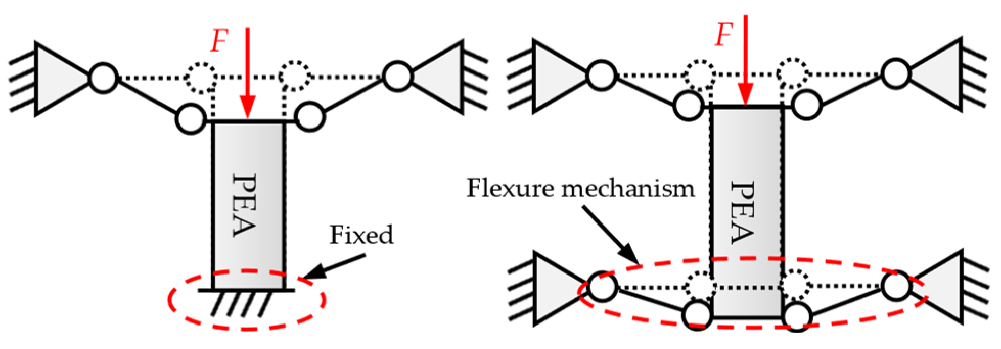
Antagonistic actuation inherits advantages such as fast response, the absence of residual strain, and high resolution, thus enabling swift and precise compensation for the ±δ μm positioning errors of stepper motors. However, in the conventional designs, the tail of each PEA is fixed to the base, as shown in the left side of Figure 2. As a result, each PEA has to bear the preload force and also the driving force of the PEA in the opposite direction. In this case, the PEA’s thrust will damage the other PEA if the load force exceeds the permissible value. To address the above problem, the fixed end of the PEA’s tail is modified to be a flexure mechanism. As shown in the right side of Figure 2, the elastic deformation of the flexure mechanism helps to reduce the stress concentration on the PEA caused by the extension of the PEA in the other direction, thus protecting the PEA.
Based on the above flexure mechanism, a compliant positioning stage with antagonistic piezoelectric actuation has been designed to improve the positioning precision in X and Y axes. As shown in Figure 3a, on each axis, two PEAs are arranged in an antagonistic configuration. Flexure parallelograms are used to transmit the actuation of the PEAs and decouple the motions of the moving platform. Due to the antagonistic actuation, the moving platform can generate bidirectional motion without applying a bias-driving voltage to the PEAs. This effectively reduces the energization time of each PEA. In the antagonistic actuation, there are two PEAs working parallel on each axis, responsible for the bidirectional movement. If one PEA fails, the other one can still provide unidirectional motion. For a single piezo-actuation system, if the PEA fails, the entire system will lose its ability to move. Therefore, the antagonistic actuation can also improve the fault tolerance and reliability of the system.
At the end of each PEA, a flexure mechanism is used to connect the PEA to the base. In the middle of the stage, sets of double parallelograms are used to connect the moving platform to the base. The double parallelograms perpendicular to the PEAs are used to transmit the PEA’s actuation, and the double parallelograms parallel to the PEA are used as a motion-decoupling structure. As shown in Figure 3a, the flexure mechanism of the compliant positioning stage can be treated as a rigid body system containing 41 rigid bodies connected by three kinds of right-circular flexure hinges (RCFHs), which are shown by kth flexure hinge (k = 1, 2 and 3) in Figure 3b. In order to easily describe the motion of each rigid body in the compliant positioning stage, the 3-DOF of each rigid body’ mass center in XY plane is expressed as generalized coordinates q(i) = [ q x ( i )   q y ( i )   q θ ( i ) ]T, where i = 1, 2, …, 41, as shown in Figure 3b.

3. Parameter Optimization and FEA Verification

In order to verify the parameter and performances of the 2-DOF compliant positioning stage, its 3D model with 190 × 190 × 10 mm3 is constructed and imported into ANSYS Workbench for FEA. The selected material is aluminum 7075 with an elastic modulus of E = 70 GPa, a yield strength of 434 MPa, and a Poisson’s ratio of v = 0.3.
Since the 2-DOF compliant positioning stage is driven by PEAs, the PEAs can be treated as force generators with built-in springs. To correctly simulate this situation, the PEAs are modeled to be spring elements. Specifically, spring elements with corresponding stiffness values of 24.39 N/μm are placed at the original locations of the PEAs, based on their effective stiffness parameters. This approach can simulate the effect of PEAs on the overall structure while avoiding the complex geometric modeling of the PEAs themselves, thereby improving computational efficiency.
In terms of meshing, in order to balance computational efficiency and accuracy, the mesh is divided by the hexahedral method with a cell size of 2 mm, which is shown in Figure 4a. To set the boundary conditions, fixed constraints are applied to the 12 circular hole positions, as shown in Figure 4b. Two equal and opposite load forces with a value of 1000 N are applied to the position of PEA4 to simulate the working state of the 2-DOF compliant positioning stage more accurately.

3.1. Parameter Optimization

The structure parameters of the RCFH and rigid body significantly influence the performance of the 2-DOF compliant positioning stage, and they should be carefully tuned. By considering the size of the PEA selected, b = 10 mm, lc = 40 mm, lpre = 42.5 mm and wpre = 61 mm are preset, respectively. There exist also the following constraints: wpre = 8Rk + 2dk + l (if k = 1, 2, l = 10; else l = lc), and sk = tk + Rk. So, there are only independent parameters that need to be tuned, namely Rk and tk (k = 1, 2, 3) of the RCFH. The working stroke is selected as the index, and the following optimization model is established to maximize it.
O b j e c t i v e : q y ( 41 ) S u b j e c t   t o = R 1 [ 2.5 ,   3.0 ] , t 1 [ 5.0 ,   6 . 0 ] R 2 [ 1.8 ,   2 . 1 ] , t 2 [ 0.5 ,   1 . 0 ] R 3 [ 1.2 ,   1 . 6 ] , t 3 [ 0.5 ,   1 . 0 ]
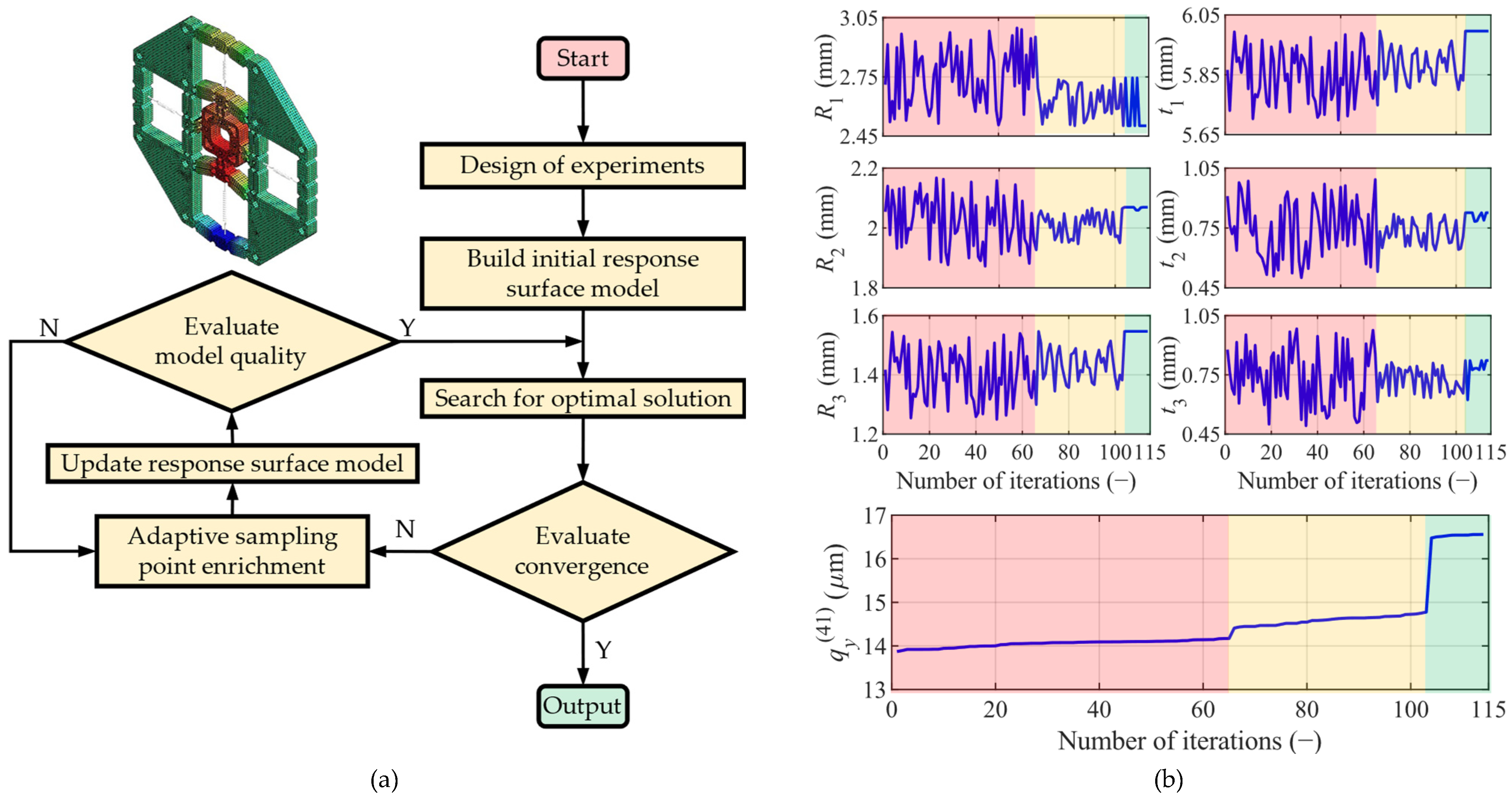
The adaptive single-objective method employs a gradient-based approach to deliver a refined, globally optimized solution. It targets a single output parameter as the objective function while accommodating multiple constraints. The algorithm’s goal is to locate the global optimum. Therefore, the built-in adaptive single-objective method in the ANSYS Workbench is employed for convergence assessment. The specific optimization settings and optimization status are presented in Table 1. According to the optimization results, the model converged after 142 design points and 1 domain reduction, with 53 failed evaluations. The size of the generated sample set is 114 points. The convergence tolerance of 1 × 10⁻⁶ is set for the output displacement of the q y ( 41 ) . Convergence is determined when the increment or relative error of it falls below this value. The corresponding optimization process is shown in Figure 5a. Meanwhile, the optimization process and results of the Rk, tk and q y ( 41 ) are shown in Figure 5b.
As can be seen in Figure 5b, the convergence state of each parameter roughly goes through the following three status:
(1).
Stochastic vibration status (the red background): This is the status where the optimization algorithm explores the parameter space extensively. The vibration phenomenon indicates that the algorithm is trying different parameter combinations, attempting to escape local optimums and find the global optimum. Vibrations at this stage are normal and indicate that the algorithm has not prematurely converged.
(2).
Decreasing vibration interval status (the yellow background): In this status, the vibration interval gradually decreases, indicating that the algorithm is searching around one or a few potentially optimal solution regions. This is the transition process of the algorithm from extensive exploration to fine-tuned search.
(3).
Convergence trend status (the green background): The value of the optimization objective function gradually stabilizes at this stage, indicating that the algorithm has approached the optimal solution. The convergence trend indicates that the optimization process has achieved a certain level of success, and the optimized values obtained can be used as a reference for the final design.
The optimized parameters of the compliant positioning stage are shown in Table 2. In addition, the optimized parameters are manually rounded to facilitate the machining.

3.2. Static Analysis and Comparison

The maximum driving force of Fin = 1000 N is applied to the input ends of the 2-DOF compliant positioning stage along the Y axis. As shown in Figure 6a, the PEA3 is compressed by 5.7 μm under the drive of the PEA4. The selected PEA in this work has a nominal stiffness of 24.39 N/μm. It can be concluded that its load force is 139.02 N, which is less than the allowable load force (400 N). In this case, the output displacement of the moving platform in the +Y direction is 16.80 μm.
The same driving force of Fin is applied to the conventional fixed-end configuration, as depicted in Figure 6b. It is observed that the stroke of the moving platform is slightly increased, whereas the PEA3 is compressed by 13.09 μm, corresponding to a load force of 319.27 N. This is approximately 2.3 times more than the proposed configuration. For PEAs, a proper preload force is generally exerted so as to increase the contact stiffness between the tip of the PEA and the flexure mechanism. For conventional fixed-end configuration, the compression force might easily go beyond the allowable range. Therefore, it is better not to maintain the PEA under prolonged high stress. The results also demonstrate the effectiveness of the proposed configuration in reducing the stress on the PEA.
Moreover, the static stress analysis is conducted to verify whether the safety factor is qualified, as shown in Figure 6c. The maximum stress is 26.85 MPa, which is far lower than the yield strength of the material.

3.3. Dynamic Analysis Results

Natural frequency refers to the inherent vibration frequency of a mechanical system without external force excitation. For a complex multi-DOF system, there will be multiple natural frequencies corresponding to different modes. Since the natural frequencies along the working direction directly determine the dynamic response performance of the 2-DOF compliant positioning stage, it is necessary to analyze the natural frequencies along X and Y axes.
Because the PEA is an elastic material, the dynamic characteristics of the 2-DOF compliant positioning stage will be affected when PEAs are installed. For the FEA modeling in dynamic analysis, the PEA can be equivalent to a spring with mass, and the installed target and its support can be regarded as a load mass on the 2-DOF compliant positioning stage, as shown in Figure 7a. The frequencies along the working direction of the 2-DOF compliant positioning stage with the PEA and load mass (1.5 kg) installed are 595.61 Hz and 596 Hz, respectively.
The high consistency between the first and second modes in Figure 7a reflects the inherent symmetry of the structure, which is a normal and expected phenomenon for symmetric structures. For such symmetric structures, it is anticipated that the lower-order-mode shapes exhibit high consistency. The third and fourth modes are the translation and rotation of the moving platform on the Z axis, respectively. As the load mass increases, the natural frequencies of the overall system gradually decrease, as shown in Figure 7b.

4. Experimental Verification

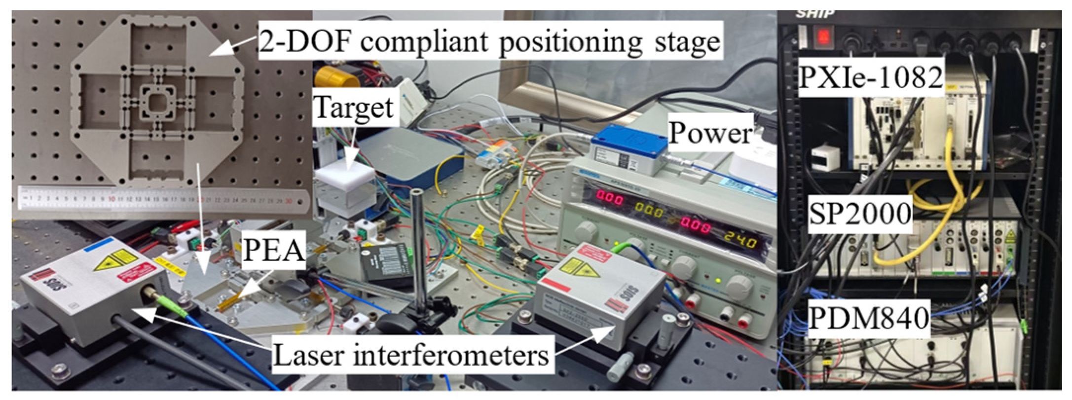
To experimentally validate the design and the 2-DOF compliant positioning stage, a 190 × 190 × 10 mm3 prototype is fabricated by Al 7075. The input displacement is generated by four PEAs (Model PK4FYP2 from Thorlabs, Newton, NJ, USA) using the voltage amplifier (Model PDM840 from Nanomotions, Shanghai, China). The output displacement of the whole system is measured by two laser interferometers with a resolution of 0.1 nm (Model SP2000 from SIOS, Thuringia, Germany). Furthermore, this model of laser interferometer is equipped with temperature sensors and an electrical noise isolation unit, which can compensate, in real time, for the impact of temperature drift and filter out the electrical noise on the measurement results. In addition, all the signals are transmitted by the PXI system (Model PXIe-1082 equipped with a PXI-8135 controller, a PXIe-6363 data acquisition card, all from National Instruments, Austin, TX, USA). All equipment and the prototype are placed on a pneumatic vibration isolation optical table to reduce the impact of external vibrations on the system. The experimental setup is shown in Figure 8.

4.1. Stroke and Coupling Performance Testing

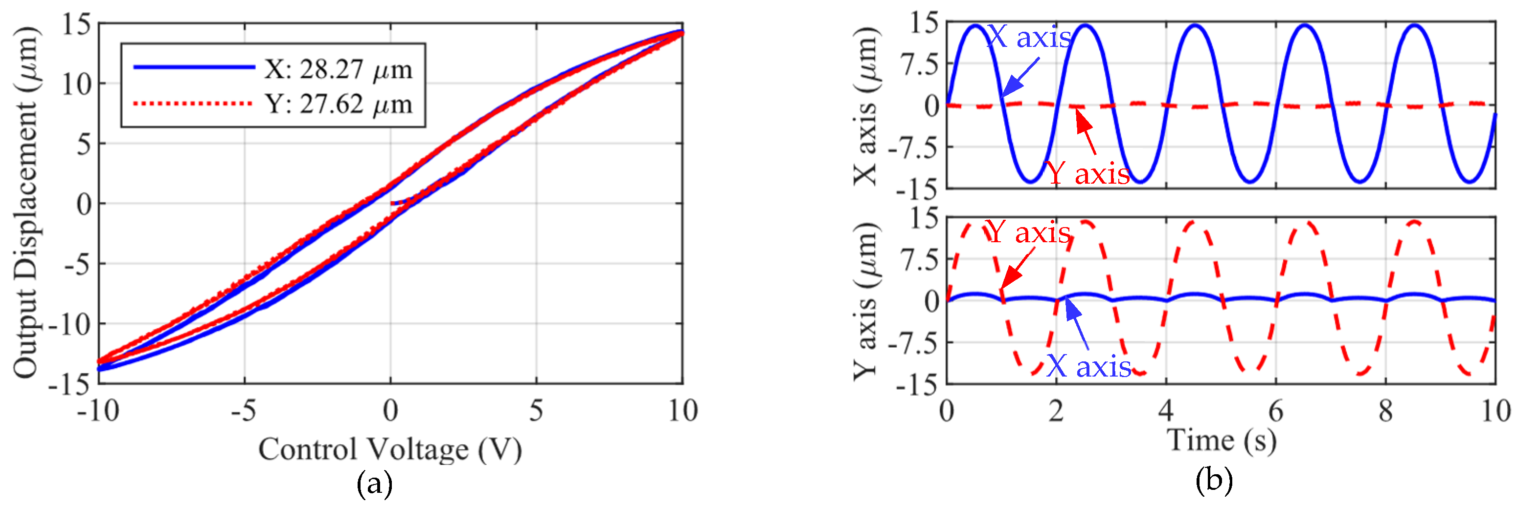
Firstly, in open-loop mode, the hysteresis loops of the 2-DOF compliant positioning stage on X and Y axes are tested to obtain its travel range. The test results are shown in Figure 9a. According to the measurements, the strokes of 28.27 μm (−13.87~14.40 μm) and 27.62 μm (−13.31~14.31 μm) can be achieved on the X axis and Y axis, respectively. As shown in Figure 9b, when only one X axis is driven by a sinusoidal signal with an amplitude of 14 μm and a frequency of 0.5 Hz, the output displacement along the Y axis is measured, exhibiting a maximum coupled motion of 0.38 μm. Employing the same driving methodology to actuate the Y axis, the maximum coupled motion observed along the X axis is measured to be 1.17 μm.
The double parallelogram structure is widely used in planar 2-DOF compliant positioning stages for decoupling purposes [42,43,44]. The maximum coupling motion is measured to be 2.64% for full stroke. It should be noted that it is very difficult to completely eliminate coupling motion by only using the decoupling mechanism. Thus, closed-loop control can be used to further reduce coupling motion.

4.2. Natural Frequency Testing

To obtain the natural frequencies of the 2-DOF compliant positioning stage along its working direction, an impact load is applied to the output end of the mechanism, allowing it to vibrate freely. This method is a widely used experimental technique in modal analysis due to its simplicity and accuracy. The excitation method does not require any prior installation or adjustment and does not introduce additional mass, stiffness, or damping to the test specimen. Additionally, this approach provides excellent mobility for the excitation location. As long as the impact force remains within the permissible range of the test object’s strength, stiffness, or precision, excitation can be achieved at locations where actuator installation is not possible.
The displacement data from the free vibration are collected and then sent to Matlab to obtain the frequency-domain signal response of the system via Fast Fourier Transform. If no PEA is installed, the natural frequencies in X and Y axes are measured to be 1323 Hz and 1327 Hz, respectively. When the PEAs are installed, the PEA’s stiffness and mass will affect the dynamic characteristics of the 2-DOF compliant positioning stage. If PEA is installed, the natural frequencies on X and Y axes increase to 2018 Hz and 2024 Hz, respectively. For the case of installed PEA and load mass (1.5 kg), the natural frequencies on X and Y axes are reduced to 598 Hz and 610 Hz, respectively. Table 3 summarizes the comparison between the experimental testing results of natural frequencies along the X and Y axes mentioned above, and the FEA. For the case of installed PEA and load mass, the maximum relative errors are 1.03% and 2.30%, respectively.

4.3. Hysteresis Compensation and Resolution Testing

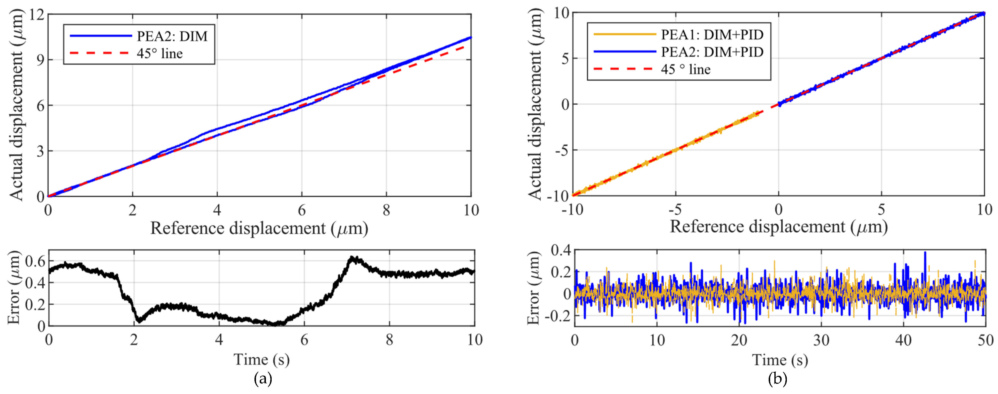
The direct inverse modeling (DIM) method [45] is used to construct feedforward hysteresis compensators for the PEAs. The modeling accuracy of the hysteresis compensator can be found in Figure 10a. Thus, proportional–integral (PI) controllers are adopted as the feedback controller to further account for the dynamic characteristics of the 2-DOF compliant positioning stage. Finally, the compensation effect of the DIM + PI composite control on the X axis is shown in Figure 10b.
To obtain the motion resolution of the moving platform in the 2-DOF compliant positioning stage in the bidirectional motion, the composite control of the DIM + PID controller is used to test the staircase input signal with an 8 nm step height. During the entire testing period, it is necessary to ensure that no unrelated personnel are present and that the testing personnel remain silent. Meanwhile, devices that may introduce weak vibrations, such as cooling fans, are briefly shut down. As shown in Figure 11, the motion resolution of the moving platform in the 2-DOF compliant positioning stage both on the X and Y axes can reach up to 8 nm.

5. Conclusions

A 2-DOF compliant positioning stage has been designed in this paper with antagonistic PEA actuation, which enables bidirectional motion along the actuation axis. Moreover, the fixed end of each PEA’s tail is modified to be a flexure mechanism to release the stress concentration on the PEA. The FEA is used to optimize the parameters of the RCFH and verify the performance of the proposed 2-DOF compliant positioning stage. A prototype is also fabricated for experimental testing. The experimental results show that the proposed 2-DOF compliant positioning stage can achieve a working range of 28.27 μm (−13.87~14.40 μm) and 27.62 μm (−13.31~14.31 μm) on the X axis and Y axis, respectively. The maximum coupling motion is measured to be 2.64% for full stroke. After installing four PEAs, the natural frequencies are 2018 Hz and 2024 Hz, respectively.
To compensate for the hysteresis of PEA and the dynamics of the 2-DOF compliant positioning stage, a combined DIM + PID control strategy is adopted. The motion resolution of the moving platform in the 2-DOF compliant positioning stage is tested to be 8 nm. Future work will focus on the design of a high-performance controller based on the proposed 2-DOF compliant positioning stage.

Author Contributions

H.W.: conceptualization, methodology, validation, formal analysis, data curation, writing—original draft preparation; H.T.: project administration, funding acquisition, review and editing; Y.Q.: Conceptualization, methodology, resources, review and editing, supervision, project administration, funding acquisition. All authors have read and agreed to the published version of the manuscript.

Funding

This work was supported in part by the Open Fund of State Key Laboratory of Precision Electronic Manufacturing Technology and Equipment under Grant JMDZ2021007, in part by the Shenzhen Science and Technology Program under Grant KQTD20210811090143060, and in part by the Natural Science Foundation of Tianjin under Grant 21JCZDJC00090.

Data Availability Statement

The data that support the findings of this study are available from the corresponding author upon reasonable request.

Conflicts of Interest

The authors declare no conflicts of interest.

References

  1. Tang, H.; Li, H.; To, S.; Yu, K.-M.; He, Y.; Gao, J.; Chen, X.; Li, J. Design and control of a new 3-PUU fast tool servo for complex microstructure machining. Int. J. Adv. Manuf. Technol. 2017, 94, 3503–3517. [Google Scholar] [CrossRef]
  2. Li, H.; Liu, J.; Liu, Y.; Li, K.; Feng, Y. Development of a resonant piezoelectric micro-jet for high-viscosity liquid using a longitudinal transducer. Mech. Syst. Signal Proc. 2021, 146, 107012. [Google Scholar] [CrossRef]
  3. Yun, H.; Liu, L.; Li, Q.; Yang, H. Investigation on two-stage vibration suppression and precision pointing for space optical payloads. Aerosp. Sci. Technol. 2020, 96, 105543. [Google Scholar] [CrossRef]
  4. Fan, Y.; He, Y.; Tan, U.X. Real-time compensation system via gyroscope and fast steering mirror for wide-bandwidth multiple-frequency vehicle disturbance. IEEE-ASME Trans. Mechatron. 2020, 25, 650–660. [Google Scholar] [CrossRef]
  5. Qin, Y.; Soundararajan, R.; Jia, R.; Huang, S.-L. Direct inverse linearization of piezoelectric actuator’s initial loading curve and its applications in full-field optical coherence tomography (FF-OCT). Mech. Syst. Signal Proc. 2021, 148, 107147. [Google Scholar] [CrossRef]
  6. Ling, M.; Yuan, L.; Zhang, X. Bionic design of a curvature-adjustable flexure hinge inspired by red blood cells. Precis. Eng.—J. Int. Soc. Precis. Eng. Nanotechnol. 2023, 81, 124–134. [Google Scholar] [CrossRef]
  7. Wei, Y.; Xu, Q. A survey of force-assisted robotic cell microinjection technologies. IEEE Trans. Autom. Sci. Eng. 2019, 16, 931–945. [Google Scholar] [CrossRef]
  8. Deng, J.; Liu, Y.; Li, J.; Zhang, S.; Li, K. Displacement linearity improving method of stepping piezoelectric platform based on leg wagging mechanism. IEEE Trans. Ind. Electron. 2022, 69, 6429–6432. [Google Scholar] [CrossRef]
  9. Mohith, S.; Upadhya, A.R.; Navin, K.P.; Kulkarni, S.M.; Rao, M. Recent trends in piezoelectric actuators for precision motion and their applications: A review. Smart Mater. Struct. 2020, 30, 013002. [Google Scholar] [CrossRef]
  10. Sabarianand, D.V.; Karthikeyan, P.; Muthuramalingam, T. A review on control strategies for compensation of hysteresis and creep on piezoelectric actuators based micro systems. Mech. Syst. Signal Proc. 2020, 140, 106634. [Google Scholar] [CrossRef]
  11. Yu, H.; Deng, J.; Liu, Y.; Wang, Y. Piezoelectric hybrid actuation mode to improve speeds in cross-scale micromanipulations. Int. J. Mech. Sci. 2023, 240, 107943. [Google Scholar] [CrossRef]
  12. Wang, D.; Liu, Y.; Deng, J.; Zhang, S.; Li, J.; Wang, W.; Liu, J.; Chen, W.; Quan, Q.; Liu, G.; et al. Miniature amphibious robot actuated by rigid-flexible hybrid vibration modules. Adv. Sci. 2022, 9, 2203054. [Google Scholar] [CrossRef]
  13. Morkvenaite-Vilkonciene, I.; Bucinskas, V.; Subaciute-Zemaitiene, J.; Sutinys, E.; Virzonis, D.; Dzedzickis, A. Development of electrostatic microactuators: 5-year progress in modeling, design, and applications. Micromachines 2022, 13, 1256. [Google Scholar] [CrossRef]
  14. Tang, Y.; Li, J.; Xu, L.; Lee, J.-B.; Xie, H. Review of electrothermal micromirrors. Micromachines 2022, 13, 429. [Google Scholar] [CrossRef]
  15. Mirvakili, S.M.; Hunter, I.W. Artificial muscles: Mechanisms, applications, and challenges. Adv. Mater. 2017, 30, 1704407. [Google Scholar] [CrossRef]
  16. Xu, Q.; Gao, X.; Zhao, S.; Liu, Y.N.; Zhang, D.; Zhou, K.; Khanbareh, H.; Chen, W.; Zhang, Y.; Bowen, C. Construction of bio-piezoelectric platforms: From structures and synthesis to applications. Adv. Mater. 2021, 33, 2008452. [Google Scholar] [CrossRef]
  17. Ouyang, P.R.; Tjiptoprodjo, R.C.; Zhang, W.J.; Yang, G.S. Micro-motion devices technology: The state of arts review. Int. J. Adv. Manuf. Technol. 2007, 38, 463–478. [Google Scholar] [CrossRef]
  18. Ouyang, P.R.; Zhang, W.J.; Gupta, M.M. A new compliant mechanical amplifier based on a symmetric five-bar topology. J. Mech. Des. 2008, 130, 104501. [Google Scholar] [CrossRef]
  19. Pinskier, J.; Shirinzadeh, B.; Al-Jodah, A. Design and evaluation of a dual-stage, compensated stick-slip actuator for long-range, precision compliant mechanisms. Sens. Actuator A—Phys. 2021, 331, 113007. [Google Scholar] [CrossRef]
  20. Tian, Y.; Huo, Z.; Wang, F.; Shi, B. Precision tracking of a 2-DOF stick-slip positioner using modeling-free inversion-based iterative control and modified inverse hysteresis compensator. Sens. Actuator A—Phys. 2021, 331, 112959. [Google Scholar] [CrossRef]
  21. Wang, J.; Huang, H.; Zhao, H. Model-based optimization for structure dimension and driving signal of a stick-slip piezoelectric actuator. Mech. Syst. Signal Proc. 2022, 164, 108191. [Google Scholar] [CrossRef]
  22. An, Y.; Ji, S.; Zhao, J. Achieving significant burst motion based on epicycloid induction principle for stick–slip piezoelectric actuator. IEEE Trans. Ind. Electron. 2023, 70, 9301–9311. [Google Scholar] [CrossRef]
  23. Tian, X.; Chen, W.; Zhang, B.; Liu, Y. Restraining the backward motion of a piezoelectric stick-slip actuator with a passive damping foot. IEEE Trans. Ind. Electron. 2022, 69, 10396–10406. [Google Scholar] [CrossRef]
  24. Qiao, G.; Ning, P.; Xia, X.; Yu, Y.; Lu, X.; Cheng, T. Achieving smooth motion for piezoelectric stick–slip actuator with the inertial block structure. IEEE Trans. Ind. Electron. 2022, 69, 3948–3958. [Google Scholar] [CrossRef]
  25. Wang, F.; Zhao, X.; Huo, Z.; Shi, B.; Tian, Y.; Zhang, D. A novel large stepping-stroke actuator based on the bridge-type mechanism with asymmetric stiffness. Mech. Syst. Signal Proc. 2022, 179, 109317. [Google Scholar] [CrossRef]
  26. Xu, Z.; Huang, H.; Dong, J. A stick-slip piezoelectric actuator with measurable contact force. Mech. Syst. Signal Proc. 2020, 144, 106881. [Google Scholar] [CrossRef]
  27. Zhang, Y.; Zhang, W.J.; Hesselbach, J.; Kerle, H. Development of a two-degree-of-freedom piezoelectric rotary-linear actuator with high driving force and unlimited linear movement. Rev. Sci. Instrum. 2006, 77, 035112. [Google Scholar] [CrossRef]
  28. Bani Melhem, M.K.; Simic, M.; Lai, C.Y.; Feng, Y.; Ding, S. Fuzzy control of the dual-stage feeding system consisting of a piezoelectric actuator and a linear motor for electrical discharge machining. Proc. Inst. Mech. Eng. Part B—J. Eng. Manuf. 2019, 234, 945–955. [Google Scholar] [CrossRef]
  29. Salton, A.T.; Chen, Z.; Zheng, J.; Fu, M. Constrained optimal preview control of dual-stage actuators. IEEE-ASME Trans. Mechatron. 2016, 21, 1179–1184. [Google Scholar] [CrossRef]
  30. Zhang, L.; Gao, J.; Chen, X.; Tang, H.; Chen, Y.; He, Y.; Yang, Z. A rapid vibration reduction method for macro–micro composite precision positioning stage. IEEE Trans. Ind. Electron. 2017, 64, 401–411. [Google Scholar] [CrossRef]
  31. Zhu, H.; Pang, C.K.; Teo, T.J. A flexure-based parallel actuation dual-stage system for large-stroke nanopositioning. IEEE Trans. Ind. Electron. 2017, 64, 5553–5563. [Google Scholar] [CrossRef]
  32. Torralba, M.; Valenzuela, M.; Yagüe-Fabra, J.A.; Albajez, J.A.; Aguilar, J.J. Large range nanopositioning stage design: A three-layer and two-stage platform. Measurement 2016, 89, 55–71. [Google Scholar] [CrossRef]
  33. Ling, M.; He, X.; Wu, M.; Cao, L. Dynamic design of a novel high-speed piezoelectric flow control valve based on compliant mechanism. IEEE-ASME Trans. Mechatron. 2022, 27, 4942–4950. [Google Scholar] [CrossRef]
  34. Tian, Y.; Lu, K.; Wang, F.; Zhou, C.; Ma, Y.; Jing, X.; Yang, C.; Zhang, D. A spatial deployable three-DOF compliant nano-positioner with a three-stage motion amplification mechanism. IEEE-ASME Trans. Mechatron. 2020, 25, 1322–1334. [Google Scholar] [CrossRef]
  35. Wei, Y.; Xu, Q. Design and testing of a new force-sensing cell microinjector based on small-stiffness compliant mechanism. IEEE-ASME Trans. Mechatron. 2021, 26, 818–829. [Google Scholar] [CrossRef]
  36. Xun, M.; Yu, H.; Liu, Y.; Deng, J.; Zhang, S.; Li, K. A precise rotary piezoelectric actuator based on the spatial screw compliant mechanism. IEEE-ASME Trans. Mechatron. 2023, 28, 223–232. [Google Scholar] [CrossRef]
  37. Mynderse, J.A.; Chiu, G.T.C. Modeling of a dynamic mirror with antagonistic piezoelectric stack actuation. J. Dyn. Syst. Meas. Control-Trans. ASME 2014, 136, 024501. [Google Scholar] [CrossRef]
  38. Jiao, C.; Wang, Z.; Lv, B.; Wang, G.; Yue, W. Design and analysis of a novel flexure-based XY micropositioning stage. Appl. Sci. 2020, 10, 8336. [Google Scholar] [CrossRef]
  39. Wang, S.; Rong, W.; Wang, L.; Xie, H.; Sun, L.; Mills, J.K. A novel linear-rotary piezoelectric positioning stage based on surface’s rectangular trajectory driving. Precis. Eng.—J. Int. Soc. Precis. Eng. Nanotechnol. 2019, 55, 376–380. [Google Scholar] [CrossRef]
  40. Liao, C.; Xu, M.; Xiao, R.; Han, W. Integrated design of piezo-actuated 2-DOF submillimeter-range super-resolution platform with self-sensing unit. Mech. Syst. Signal Proc. 2020, 139, 106569. [Google Scholar] [CrossRef]
  41. Xie, Y.; Li, Y.; Cheung, C.F.; Zhu, Z.; Chen, X. Design and analysis of a novel compact XYZ parallel precision positioning stage. Microsyst. Technol. 2020, 27, 1925–1932. [Google Scholar] [CrossRef]
  42. Yang, Y.; Wen, J.; Zhang, Y. Development of a novel XZ workpiece vibration generator for cooperative vibration cutting of hierarchical grating structures. Mech. Syst. Signal Proc. 2023, 198, 110422. [Google Scholar] [CrossRef]
  43. Huang, W.-W.; Li, L.; Zhu, Z.; Zhu, L.-M. Modeling, design and control of normal-stressed electromagnetic actuated fast tool servos. Mech. Syst. Signal Proc. 2022, 178, 109304. [Google Scholar] [CrossRef]
  44. Zhang, Q.; Zhao, J.; Peng, Y.; Pu, H.; Yang, Y. A novel amplification ratio model of a decoupled XY precision positioning stage combined with elastic beam theory and castigliano’s second theorem considering the exact loading force. Mech. Syst. Signal Proc. 2020, 136, 106473. [Google Scholar] [CrossRef]
  45. Qin, Y.; Tian, Y.; Zhang, D.; Shirinzadeh, B.; Fatikow, S. A novel direct inverse modeling approach for hysteresis compensation of piezoelectric actuator in feedforward applications. IEEE-ASME Trans. Mechatron. 2013, 18, 981–989. [Google Scholar] [CrossRef]
Figure 1. Compensation for the ±δ μm positioning errors of the stepper motor.
Machines 12 00420 g001
Figure 2. Comparison of PEA under different boundary conditions.
Machines 12 00420 g002
Figure 3. (a) Structure design of the proposed 2-DOF compliant positioning stage, (b) flexure hinges connected ith rigid body.
Machines 12 00420 g003
Figure 4. Initial setup for FEA: (a) meshing and (b) boundary conditions.
Machines 12 00420 g004
Figure 5. (a) Optimizing the flow of the adaptive single-objective method and (b) optimization process of the Rk, tk and q y ( 41 ) .
Machines 12 00420 g005
Figure 6. Static analyses of the 2-DOF compliant positioning stage: (a,b) deformation of the proposed and the conventional configuration; (c) the stress distribution.
Machines 12 00420 g006
Figure 7. (a) Mode shapes of the 2-DOF compliant positioning stage with PEAs and load mass, (b) relationships between the natural frequencies and the load mass and the (c) region of load mass.
Machines 12 00420 g007
Figure 8. Experimental setup.
Machines 12 00420 g008
Figure 9. (a) Hysteresis curve and the (b) coupling of the proposed 2-DOF compliant positioning stage.
Machines 12 00420 g009
Figure 10. Hysteresis compensation results: (a) DIM method and (b) DIM+PID method.
Machines 12 00420 g010
Figure 11. The motion resolution of the proposed 2-DOF compliant positioning stage: (a) X axis, (b) Y axis.
Machines 12 00420 g011
Table 1. Optimization settings and optimization status of adaptive single-objective method.
Optimization SettingsOptimization Status
PropertyValuePropertyValue
Estimated number of
design points
220Number of design points142
Number of
initial samples
66Number of
domain reductions
1
Maximum number
of evaluations
220Number of failures53
Convergence
tolerance
1 × 10⁻⁶Size of generated
sample set
114
Table 2. Main parameters of the 2-DOF compliant positioning stage.
ParameterValue (mm)ParameterValue (mm)
R12.5020→2.50t15.9960→6.00
R22.0688→2.10t20.8624→0.80
R31.5886→1.60t30.8228→0.80
d115.492→15.5d34.1456→4.10
d217.224→17.1
“A→B” indicates that the value of B is obtained by manually rounding the value of A.
Table 3. Natural frequency of the 2-DOF compliant positioning stage.
FEA (Hz)Exp. (Hz)
X AxisY AxisX AxisY Axis
Without PEA1457.41450.71323.01327.0
With PEA2064.02070.52018.02024.0
With PEA and load mass595.60596.00598.00610.00
Disclaimer/Publisher’s Note: The statements, opinions and data contained in all publications are solely those of the individual author(s) and contributor(s) and not of MDPI and/or the editor(s). MDPI and/or the editor(s) disclaim responsibility for any injury to people or property resulting from any ideas, methods, instructions or products referred to in the content.