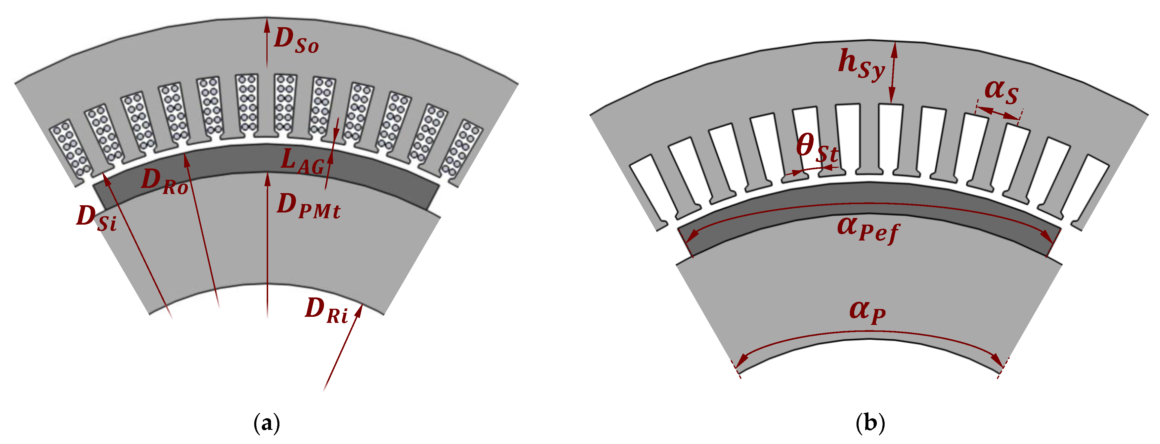
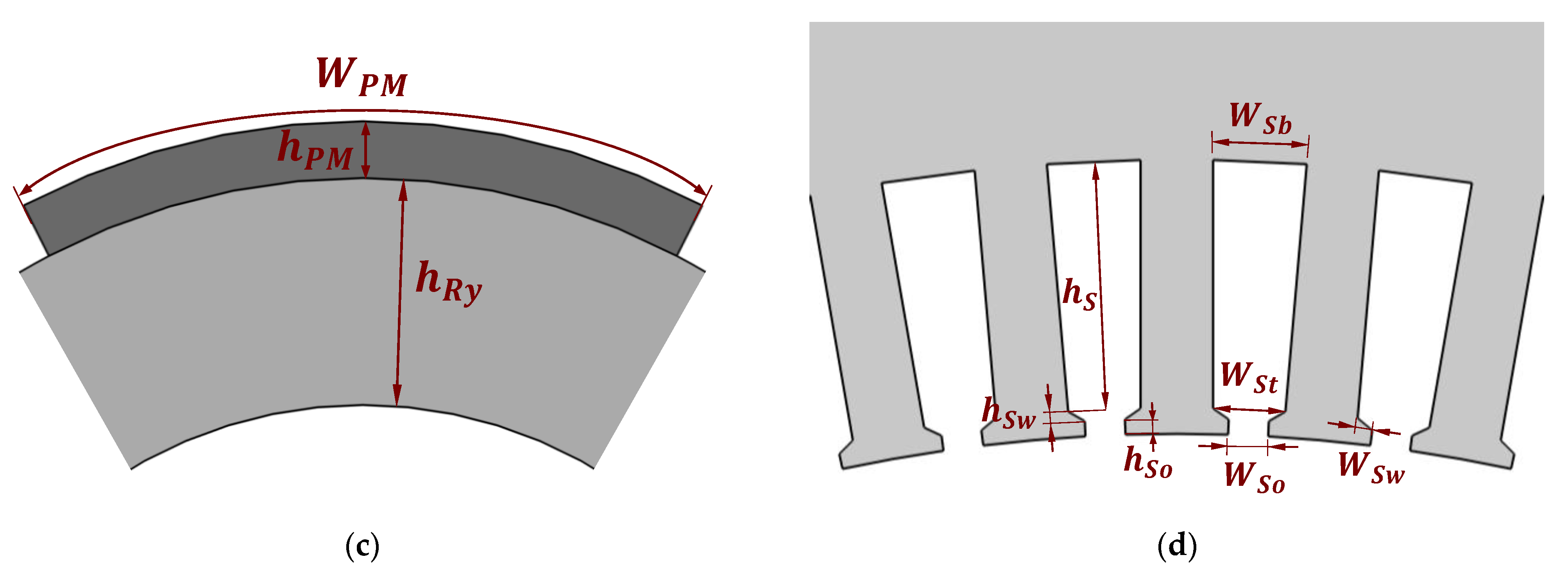
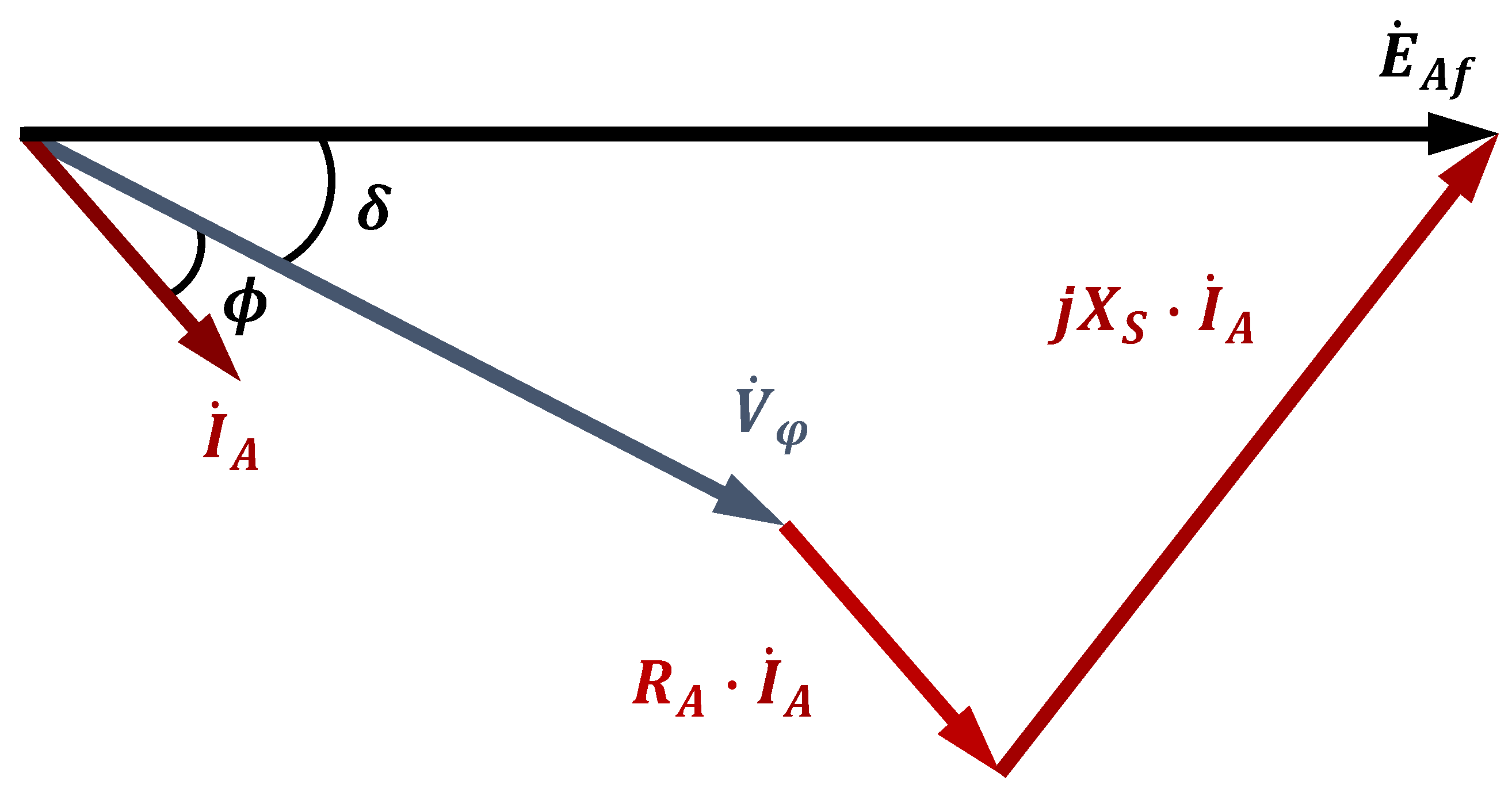
2.2. Design Procedure
Before initiating the design, a few basic characteristics must be defined, such as the machine type (asynchronous, synchronous, etc.) and type of construction (external rotor, internal rotor, axial flux, radial flux). Thereafter, the first step of the design consists of defining the specifications of the generator, such as the apparent power, desired power factor, rated angular speed, rated frequency, rated terminal voltage, and number of phases [
3]. Using this information, it is possible to obtain the physical dimensions of the electrical machine, define the material properties winding characteristics, and draw up manufacturing instructions.
Even though the specifications can be the same for different types of machines, a single design procedure does not apply to all types of machines. Therefore, adaptations to well-established methodologies to better adapt to the particular needs of the designer become relevant [
4]. Thus, the proposed design methodology for surface-mounted permanent magnet synchronous generators (PMSGs) is based on the design procedure developed in [
1] for salient pole wound-rotor synchronous generators. The rotor sizing part of the design was entirely developed in this paper, whereas the stator sizing is very similar to the mentioned reference.
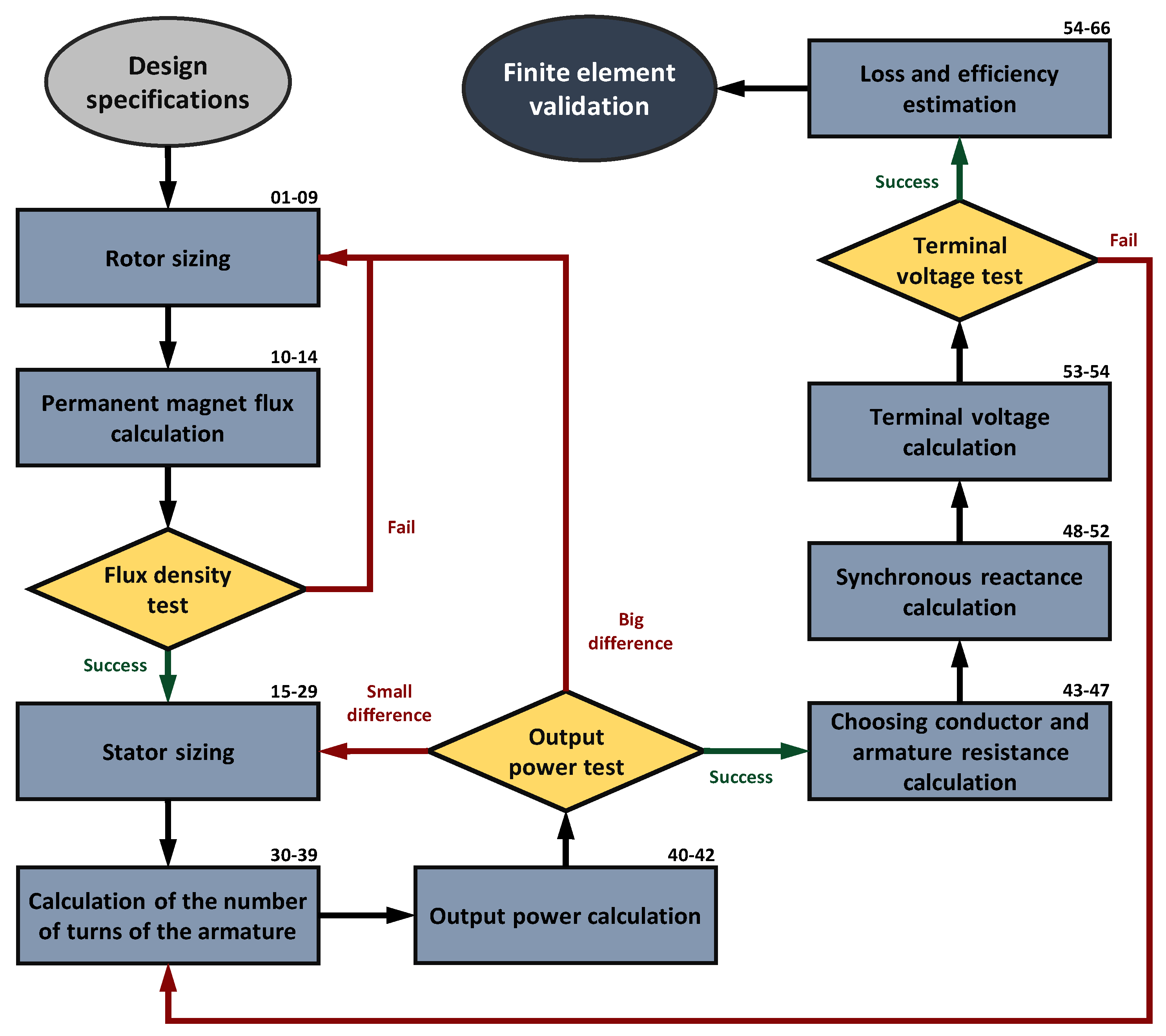
The proposed design methodology is composed of 66 analytical equations, and the general flowchart is shown in
Figure 2. From the specifications, the majority of the generator dimensions, presented in
Section 2.1, are calculated with analytical equations, and the remaining dimensions are found using parameters imposed by the designer. The proposed method is an iterative design procedure that allows for adjustments of dimensions and parameters so that the calculated values match the design specifications in a very straightforward manner. The iterations within the procedure happen with the flux density, output power, and terminal voltage tests. Furthermore, the rectangular blocks in the flowchart of
Figure 2 represent the design stages of the procedure, and each one has a subsection dedicated to explaining its steps. Every stage is composed of a set of equations (steps), and the numbers can be seen in the right corner of the corresponding stage in
Figure 2.
As shown in
Figure 2, the proposed design procedure begins with the specifications, followed by sizing the rotor and stator to find all their dimensions. In the rotor sizing (
Section 2.3.1), the first steps depend on defining the rotor external diameter. This design methodology considers it an input parameter known by the designer, either from a previous calculation (which can be found in [
3,
4,
11,
19]) or by experience. The remaining rotor dimensions, such as the PM dimensions and the rotor internal diameter, are found using a few imposed parameters and with the desired magnetic flux density in the rotor core, respectively.
Knowing all PM dimensions, and after defining the PM type, operative temperature, and permeance coefficient, the design proceeds to PM flux calculation (
Section 2.3.2), as
Figure 2 shows. Thus, with the air gap length and the generator axial length, the flux in the air gap is calculated and used to find the air gap flux density. If this flux density is not within the desired range, the PM permeance coefficient can be increased or decreased to have more or less magnetic flux density in the air gap, respectively. Another solution would be changing the PM grade, which is a specification that indicates its energy. However, higher grades also mean higher PM costs [
5].
According to
Figure 2, with an acceptable air gap flux density, the design proceeds to stator sizing (
Section 2.3.3), where a few imposed parameters are used once more and the stator teeth and slot dimensions are found. Then, the armature windings are defined (
Section 2.3.4), with the armature conductor surface being the final obtained parameter. Based on the previously calculated flux of the air gap, the number of turns per coil of the armature winding is found using an imposed no-load voltage value. With the slot surface and the number of turns, the armature conductor surface can be found. Considering the previously set maximum conductor current density, the conductor surface is then used to obtain the armature current.
As shown in
Figure 2, the next step is the output power calculation. By using the desired terminal voltage value and the armature current from the previous step, the admissible output power can be calculated (
Section 2.3.5). Even though the specified terminal voltage value is used, this is not an inconsistency of the proposed design methodology since the procedure is only completed after matching the calculated terminal voltage value with the specifications (explained further in this subsection). Calculating the admissible output power at this early stage of the procedure allows the designer to assess whether the machine’s latest size and dimensions correspond to a solution not too far from the desired output power.
If this value does not correspond to the apparent power from the specifications, a few parameters can be adjusted, either from the rotor or from the stator design, as depicted in
Figure 2. Since the terminal voltage is a design specification (meaning its value is fixed), output power adjustments must be made that target the armature current by changing the conductor cross-section, either by changing the slot dimensions or by reducing the number of turns of the windings. Since in this design methodology the stator sizing defines an armature conductor that can be fitted in the slots, for minor differences, this can be done by adjusting the machine’s stack length or the slot geometry.
For example, increasing the generator length would result in more flux linked by the armature coils; thus, fewer turns are required to match the terminal voltage, and consequently, a bigger conductor cross-section may be used. Ultimately, this results in a bigger value of admissible current while maintaining both the same slot area and the specified current density. On the other hand, increasing the slot area directly allows for a bigger conductor surface when maintaining the number of turns in the armature coils. Thus, more armature current is admissible while keeping the same current density. Evidently, this logic can be applied when adjustments must be made to decrease the admissible output power of the generator.
If the admissible power is too far from the specified value, more significant changes are necessary. In this case, parameters in the rotor sizing should be adjusted since the current PM volume does not produce the flux that, when linked by the armature coils, corresponds to the desired output power. Either the PM flux is less than what is needed and more turns are required, which reduces the conductor surface, or too much flux is produced and fewer turns are needed to match the imposed voltage value, which allows for a bigger conductor. In this case, the rotor outer diameter or the effective pole pitch can be adjusted. The latter must be more carefully altered since it greatly impacts flux leakage. It is not recommended to alter the armature current density since this value is usually chosen to guarantee operation under maximum temperature or is determined by a thermal model.
The proposed method has a noteworthy difference from other design methodologies concerning the output power calculation and the iterative process discussed previously. As seen in
Figure 2 and explained earlier in this subsection, the proposed design comes from rotor sizing to stator sizing, where the slot area is defined; then, with the number of turns of the armature coils, the conductor cross-section that can be fitted within the slots is calculated, the armature current is found and, consequently, the admissible output power is found. In other design methodologies ([
9,
23,
24], for example), this part is inverted, where, with the specified output power and terminal voltage, the armature current is calculated, which is then used to find the conductor cross-section after defining the armature current density. Thus, the slot dimensions are found so that the slot area can accommodate the previously found conductor. With this approach, the design is susceptible to resulting in a too-large stator compared to the rotor and would only be noticed by the designer when the generator is drawn. On the other hand, with the proposed approach, the designer deals directly with the dimensions and quickly assesses their relation to the output power. Furthermore, performing the iterative process of the output power test, the relation between the generator rotor and stator dimensions becomes clearer and clearer.
At the end of the output power design stage, all generator dimensions are known, and then the loading effects have to be considered before proceeding with the design method, as
Figure 2 shows. Firstly, a combination of copper conductors (or a single one) is chosen to match the calculated armature conductor surface. From its specifications, the armature resistance is found (
Section 2.3.6). During load operation, the armature current creates a magnetic field that interacts with the rotor magnetic field, resulting in distorted net flux density with a decreased or an increased value, depending on the load. This corresponds to a smaller or bigger terminal voltage (with inductive and capacitive loads, respectively). This armature reaction field can be electrically represented by a reactance, so obtaining this value is an essential design step. For non-salient pole PM machines, the reluctance of the air gap is constant, regardless of the position of the rotor, as the magnetic permeability of the magnets is very close to that of air. Thus, the armature reaction reactance does not assume different values depending on the rotor position and can be analytically calculated since the rotor geometry is less complex than in other types of PM machines.
In addition to the armature reaction reactance, the armature coils also have a leakage inductance, which becomes leakage reactance when multiplied by the synchronous speed of the machine. Adding these two reactance values results in the synchronous reactance of the generator (
Section 2.3.7). After calculating the voltage drops in the armature resistance and the synchronous reactance, the terminal voltage is estimated (
Section 2.3.8) and should be compared with the desired voltage value from the specifications. As shown in
Figure 2, in the case of a difference, the designer should adjust the imposed voltage used in the design step that calculates the number of turns of the armature coils per phase. A new value would result in more or fewer turns for the same rotor dimensions and air gap flux. Since the design is taken back to the armature definitions, the output power assumes a new value in the next stage, and naturally, adjustments should be performed. How to perform these adjustments was discussed earlier, where minor differences require less effort from the designer, and a big difference may take a few more iterations and eventually take the design back to stator or rotor sizing.
When the terminal voltage matches its desired value, the next stage consists of a loss estimation (
Section 2.3.9) to further compute the generator efficiency, as
Figure 2 shows. The proposed design procedure considers copper losses in armature windings, iron losses in the stator core, and permanent magnet losses. Finally, after calculating the efficiency, the surface-mounted permanent magnet generator design is completed. If the designer is satisfied with the designed generator, then a finite element simulation should be carried out. This way, a thorough analysis can be realized, and the designed machine can be eventually verified.
2.4. Imposed Parameters and Their Suggested Ranges
In the proposed design procedure, the designer has to determine a considerable number of imposed parameters. Thus, this section addresses these parameters seen throughout
Section 2.3 since they significantly impact the generator’s results. To explain in the most straightforward manner possible, this section follows the same order as the previous section, going from rotor sizing all the way to losses and efficiency estimation. The suggested ranges are mostly based on the literature and papers that address the matter; they may be seen in summary in
Table 1.
As explained in
Section 2.2, after defining the design specifications, the rotor outer diameter (
) should be chosen. To simplify the design procedure, the equations that guide the external rotor diameter calculation were not included since they can be found in several works in the literature ([
3,
4,
11,
19]). Thus, the proposed method treats it as an imposed parameter, allowing the designer to find it with one of the methods in the mentioned literature or to freely choose it based on their experience. Alternatively, it is possible to follow the “ABC” procedure presented by [
4], where the torque per unit of rotor volume (and consequently the rotor external diameter) is obtained from the electric and magnetic loadings, assuring proper temperature rise. This procedure can be carried out by adopting the range values suggested by [
3]. The imposed
, presented in
Table 1, implies on the values of electric loading (A/m) and flux densities (T) according to reference values from [
3].
After analyzing the electrical machine design equations, it becomes clear that the machine’s electrical power is proportional to its volume (considering the same rotational speed). This means that it is not possible to suggest a range for the rotor outer diameter since it heavily depends on the desired output power of the generator. Even though stator dimensions also affect the outer diameter of the machine (and consequently its volume), most of the stator dimensions are attached to the PM dimensions, which in turn are proportional to the rotor outer diameter (which can be seen in
Section 2.3.1).
2.4.1. Rotor Parameters
Regarding rotor sizing, four parameters need to be imposed by the designer: the pole pitch factor (), air gap factors (), the permeance coefficient (), and the desired magnetic flux density in the rotor yoke (). Firstly, the pole pitch factor determines the angle occupied by the PM, defining how much of the entire pole pitch () can be effectively used to produce flux (). Permanent magnet machines, in general, should not utilize the entire pole pitch. Utilizing the entire pole pitch in surface-mounted machines would mean that the permanent magnets of adjacent poles would be in contact with each other, resulting in significant leakage flux since the flux lines will feel a path of lesser reluctance compared to the one crossing the air gap. It is also not advised for the PM to occupy less than half of the pole, resulting in low rotor volume utilization.
The generator air gap length (
) is an extremely important parameter, and it is recommended to keep it as small as possible to maximize the PM flux. However, in addition to torque ripple under load operation, other vibration sources can cause contact between the rotor and stator; thus, a safety margin should be considered. To ensure a reasonable proportion between the air gap length and rotor size, the value of the air gap factor (
) should be determined considering manufacturing and mechanical aspects. A good reference would be to keep the value between 0.01 and 0.015 (meaning an air gap length of 1% to 1.5% of the rotor’s outer diameter) [
1].
Since the permeance coefficient (
) is better explained in the next section, the last imposed parameter of the rotor sizing is the magnetic flux density in the rotor yoke (
). At no-load operation, the flux density in the rotor yoke tends to be proportional to the PM width since the PM flux divides itself in the yoke on both sides. Thus, by dividing the PM operative flux density by the desired flux density in the yoke (at no load) and multiplying by the PM width, the yoke height (
) is found. According to [
3], the flux density in the rotor yoke should be between 1.0 and 1.5 T during full-load operation. Therefore, since the
value is imposed in a no-load part of the design, the designer should consider a safety margin to ensure that this range is still respected during full load.
2.4.2. Permanent Magnet Flux Parameters
In the permanent magnet flux calculation, one of the most important values is the operative permanent magnet flux density (
, which is obtained from the PM demagnetization curve. Even though it was first used in a previous section, the permeance coefficient (
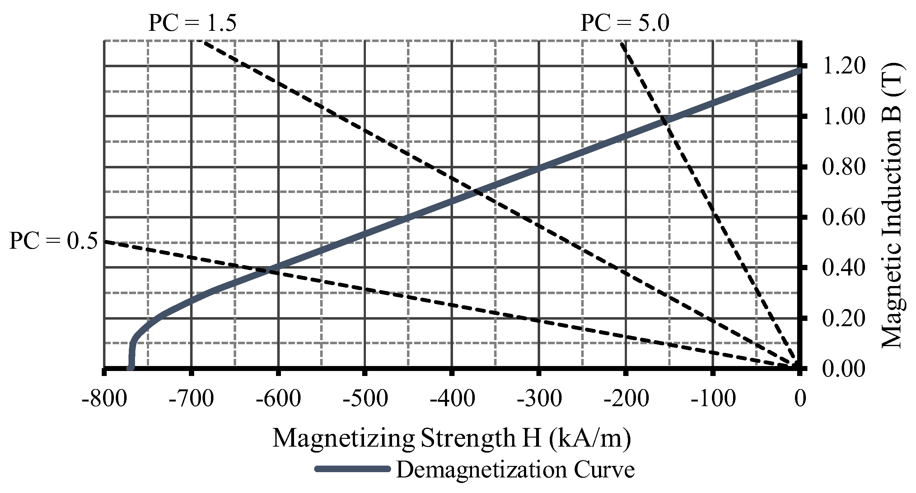
) is a paramount parameter for the PM flux calculation. To better explain how this operative flux density is extracted and the PC influences this process, the demagnetization curve of the neodymium–iron–boron PM N42SH from [
39] is depicted in
Figure 4.
The
is the inclination of the load lines (dotted) that intersect the permanent magnet demagnetization curve (blue continuous line) in
Figure 4. Each intersection corresponds to a PM operating magnetic flux density (
) at no load. Assuming that the cross-sectional areas of the permanent magnet and the air gap are very close values, that the air gap flux leakage is low, and that the permeability of the electrical steel used in electric machines is thousands of times greater than that of air, with both Ampère’s and Gauss’s laws the PC can be described as
[
5]. Therefore, with the air gap length, choosing the permeance coefficient defines the PM height (
and its operative magnetic flux density at no load.
As shown with the different
values in
Figure 4, increasing it moves the no-load operating flux density towards the PM remanent flux density, which is the maximum that the PM can generate (while maintaining the same temperature). On the other hand, smaller values correspond to a smaller operating flux density, bringing the PM operating point closer to the knee of the demagnetization curve, which could cause permanent demagnetization [
4]. There is no consensus concerning a correct range for the
value. The authors of [
6] suggest a
of between 5 and 15, whereas the authors of [
4] suggest a smaller range of 5 to 10, and the authors of [
15,
23] follow the range indicated by [
5], which is between 4 and 6.
In the proposed design methodology, values between 3 and 8 can be used as long as the designer is conscious that a safety margin should ensure that during load operation (and even under overload transients) the PM is not under the possibility of having permanent demagnetization. Additionally, even though the permeance coefficient may assume values more in the middle of the suggested range (or even towards the upper limit), too-small PM heights are usually more complicated to manufacture [
4,
5,
6]. Values close to the top end of the suggested range would result in a bigger PM height (and volume) and no-load operative flux density. Normally, this would also increase the machine cost; however, shortening the machine stack length could adjust the generator price and result in the same flux linked by the coils as a smaller PC.
At the very beginning of the design procedure, a permanent magnet and its permeance coefficient are chosen. In the performed design of
Section 3, the neodymium–iron–boron of grade 42 and thermal class SH was selected. Moreover, as the demagnetization curve depends on the operating temperature of the PM, a maximum temperature rise of 100 °C was considered. This results in an operative temperature (
) of 120 °C if the ambient temperature is considered to be around 20 °C. Therefore, the correct demagnetization curve of the N42SH from the spreadsheet of its manufacturer [
39] is the one for 120 °C, as shown in
Figure 4.
Another parameter necessary to calculate the PM flux is the generator stack length (
), found by imposing a value for the machine shape factor (
, which usually assumes values between 0.5 and 2. For the lower half of this range, the axial length of the rotor is smaller than its diameter, resulting in more rotor inertia than upper values in the suggested range. Additionally, the efficiency of the machine tends to be lower, as there is relatively more copper in the coil ends. For values between one and two, the rotor has lower mechanical stress, but cooling the machine becomes more costly [
19].
To find the flux in the air gap of the machine, the permanent magnet to air gap leakage factor (
) is used to consider the leakage flux that tends to return to the adjacent pole (or even the opposite side of the same PM) and does not reach the air gap. Its value can be obtained with reluctance networks or finite element simulations (FESs) of the generator under no-load operation. With this factor value, the designer can more accurately assess whether the designed PM corresponds to the desired air gap magnetic flux density, which should be between 0.85 and 1.05 T [
3].
Similarly to the permanent magnet to air gap leakage factor that accounts for the leakage flux from the PM that does not reach the air gap, the air gap to armature leakage flux factor () is used in the calculation of the number of turns of armature winding () to consider the flux that is not linked by the coils, returning to the air gap through the stator teeth. This factor may also be adjusted after performing a magnetostatic no-load finite element simulation of the machine, which does not take more than a few seconds.
2.4.3. Stator Parameters
The stator sizing begins with choosing the number of slots (
), which is strictly linked to the number of poles since their ratio strongly affects the machine’s winding scheme and the presence of harmonics of certain orders. Additionally, the ratio between the number of poles and slots, together with the slot opening width, influences the presence of cogging torque. Furthermore, this tends to become a constrained choice since the number of slots and their layers are limited by production feasibility and winding manufacturability aspects [
3]. Therefore, since synchronous machine winding is an extensive topic alone, the recommendation here is to choose the number of stator slots so that the number of coils per pole per phase is an integer, preferably between 1 and 4. As a reminder, this is a recommendation; other values (even non-integer ones) could be used as long as the designer knows the subject very well and its repercussions for the design.
Subsequently, the slot sizing requires definitions of the slot opening and the tooth dimensions. These dimensions have an impact on the cogging torque and Foucault losses, demanding special care and experience from the designer [
5]. Due to their significance in the overall result, in this design procedure they are linked in an attempt to maintain reasonable proportions and allow inexperienced designers to find an appropriate PM generator geometry.
Firstly, the slot opening width () is bounded to the rotor outer diameter and the number of stator slots, ensuring that proportion with the overall size and number of slots of the machine is established. To adjust this proportion, aiming for the slot width to be feasible (in terms of manufacturability) and allowing the armature conductors to be inserted in the slots, the slot opening factor () is used. It is not elementary to suggest a range of values for this imposed parameter since it can vary substantially, but a range between 0.25 and 1 should cover most cases.
The remaining tooth tip dimensions being linked to the slot opening (seen in Equations (17) and (18)) would avoid excessively thin or too-long and -fragile tooth tips. Both the slot opening height factor () and the wedge height factor () could assume values between 0.25 and 1. Ultimately, the tooth tip proportions can only be verified when the stator sizing is finished and the generator cross-section is drawn. However, with the slot wedge dimensions (imposed slot wedge height and slot wedge width calculated with Equation (24)), the wedge inclination can be found and analyzed. An imbalance between wedge height and width can be easily noticed if this value becomes smaller than 20 or bigger than 40.
Also during the stator sizing, a proportion of how much of the slot pitch corresponds to the slot or the stator teeth is defined by the tooth-to-slot-width factor (
). As the value of this imposed parameter increases, the slot begins to occupy a smaller portion of the slot pitch, reducing the total slot area, which reduces the armature conductor surface and, therefore, the power produced in the stator volume. On the other hand, decreasing the value of this imposed parameter reduces the tooth width (
) and increases its flux density, which can lead to saturation. Therefore, this parameter could assume values within the 0.8 to 3 range. The designer can assess whether the stator teeth are close to saturation at no-load operation by calculating the teeth average magnetic flux density
. The flux density in the stator teeth should be between 1.5 and 2.0 T [
3] at full-load operation; thus, similar to the imposed rotor yoke flux density, the
should also consider a margin so that the stator teeth will not saturate when the generator feeds a rated load. The magnetostatic simulation used to adjust the leakage flux factors can also be used to verify whether this range is respected and whether there is a reduced risk of saturation.
Seeking to establish a certain relationship with the flux density produced by the magnets with the maximum flux density in the stator yoke, its height (
) is chosen to be a portion of the width of the magnets—seen in Equation (25). Keeping the permanent magnet width to stator yoke factor (
) to between 0.25 and 1 makes it possible to avoid designing an unnecessarily large stator with a low air gap flux density or an overly saturated one. The flux density in the stator yoke should be kept between 1.0 and 1.5 T [
3] at full load. Thus, using
, the designer can assess whether a margin is reasonable and ensure that this would not exceed the flux density recommended by [
3]. Lastly, for PM generators with many poles, defining the stator yoke height only by its desired flux density can lead to excessively thin yokes. In this case, a mechanical constraint can be incorporated.
Lastly, the slot height (
) is tied to the stator yoke height with the stator yoke to slot height factor (
). Even more than the width, the slot height influences the power density of the machine, as with larger slots it is possible to increase the conductor’s surface, allowing for more current. As discussed in
Section 2.2, with this approach, in essence, the designer freely defines the generator output power by imposing the last two factors instead of choosing an armature conductor based on the output power and then finding the slot dimensions to fit the conductors. Additionally, a proportionality between the volume of magnets and the volume of copper in the stator is also ensured indirectly. The suggested range is also between 0.25 and 1.
2.4.4. Armature Winding Parameters
During the armature-winding definitions, a coil-shortening factor (
) is defined to calculate the armature coil pitch (
). Usually, the coil pitch is shortened so that the length of the coil end becomes shorter and the total copper mass is reduced [
4]. This results in a smaller armature resistance and fewer copper losses, which increases the efficiency of the generator since it is the most significant loss in synchronous generators. Furthermore, with the correct factor value, the shortened coil can attenuate the harmonic content of the air gap flux density and result in a more sinusoidal linked flux compared to a full-pitch coil [
3].
The armature coil-shortening factor is a fraction of the original pole pitch, composed of values multiple of the original pitch, resulting in an integer shortened pitch. Since many combinations between the number of poles and stator slots are possible, this fraction can be composed of a large quantity of multiples. Shortening factors of 2/3 and 5/6 are more conventional, known to reduce significantly third and ninth-order components and fifth and seventh-order components, respectively [
1,
3].
To find the component of the winding factor (i.e., the winding distribution factor
), the number of slots per pole per phase must be found, which depends on the number of phases of the generator (
). This can be selected freely in principle, but since most supply networks are three-phase, most electrical machines are three-phase [
3].
Further regarding the proposed design methodology, one of the most important parameters is defined: the number of armature-winding turns per phase (), calculated with Equation (34). This equation is basically Faraday’s law, i.e., the voltage induced in a coil depends on the time variation of the linked flux and the number of turns, with the addition of flux linkage reduction factors due to coil shortening (), winding distribution (), and flux leakage (). Thus, in essence, the number of turns is found based on the flux produced by the PM and the imposed voltage value ().
To more effectively elucidate how this voltage value can be chosen, the WRSG design is used. In this case, the voltage value used to calculate the number of turns is the no-load voltage, given that for both no-load and full-load conditions it is possible to adjust the rotor-winding excitation and maintain the specified terminal voltage [
1]. This is not the case for permanent magnet generators since the PM flux cannot be adjusted dynamically according to the generator load. Therefore, for PMSG, the voltage value used to calculate the number of turns of the armature winding must be the induced voltage estimated to be generated when feeding a load, which has to be big enough to be equal to the desired terminal voltage after the voltage drops in the armature resistance and due to the armature reaction.
This is an iterative stage of the design (depicted in
Figure 2) since it is very unlikely that the first imposed voltage value will precisely correspond to the desired terminal voltage in the specifications. However, matching the calculated terminal voltage to the specified value usually takes only a few iterations. An adequate first guess could be a voltage 1.3 times bigger than the phase value of the specified terminal voltage. After calculating the terminal voltage with Equation (54), this value is adjusted, but related parameters should eventually be adjusted concurrently.
For example, increasing would result in more turns per coil; thus, a smaller conductor cross-section can be fitted in the slots. Considering that the stator geometry (slot dimensions) and the stator current density are not altered, less armature current is admissible, corresponding to less admissible output power. To correct that, the generator stack length could be adjusted, meaning more linked flux, and the number of turns would be restored to the previous value (this is the simpler way to deal with that since the cross-section of the generator remains the same). Another way would be to adjust the slot size, allowing a bigger conductor surface that results in the original output power. However, the designer should know that this changes the value of the air-gap-to-armature-leakage factor ().
Instead of just imposing a generic number of turns, defining a voltage value () is more palpable since it would be the equivalent of expecting a voltage regulation (of 30%, for example). Furthermore, if the proposed method were to be implemented in optimization software, the algorithm itself would be capable of finding the exact value of , because the terminal voltage and output power are fixed variables.
The last imposed parameters that define the armature windings are the consequent pole factor (
), the number of slot layers (
), and the number of parallel paths in the armature windings (
). Both
and
are either 1 or 2. For the consequent pole factor, a value of 2 would be chosen to have a consequent pole armature winding. The number of parallel paths in the armature windings is a multiple of the number of poles [
1]. For example, for a six-pole generator,
could be 1, 2, 3, or even 6. However, in this paper the suggestion is either 1 or 2. Again, this is a recommendation; other values can be used for specific cases or applications as long as the designer is aware that this will deeply impact the generator’s winding scheme. With these values, both the number of coils in series per phase (
) and the number of coils per pole per phase (
) are found.
Lastly, before moving on to the armature current (
) calculation, the designer must impose values for the slot fill factor (
) and the admissible armature current density (
). Considering that it is not possible to fill the slot entirely with conductors due to the conductor’s insulation and manufacturability aspects, a slot fill factor is considered. The main aspects include the techniques available during manufacturing (allowing perfectly nested conductors or not), square or round conductors, and single- or double-layer [
6]. Usually, slot fill factors between 40 and 45% are a bit optimistic for random-wound coils, and for higher values, rectangular wires more precisely fitted are required [
4]. Thus, in this paper, a range between 30% and 60% is suggested.
Finally, the current density in the armature conductors must be carefully analyzed, considering two major aspects. The first is the operation temperature of the generator, which is intensely related to the thermal class of the conductors’ insulation. High-thermal-class insulation materials can sustain higher operation temperatures, thus allowing more current density. The last is the cooling system chosen, with a high-efficiency cooling method allowing more current density. In more complex design procedures that include a thermal model of the generator, the operating temperature of the armature winding can be an imposed parameter, so the conductor current density is a free parameter. To simplify the design procedure, the imposed current density in the armature conductors is suggested to be within 4 and 6.5 A/mm
2 [
3].
2.4.5. Armature Resistance Parameters
To find the resistance per kilometer of the conductor (), firstly, the designer should choose the number of wires that correspond to a conductor. If a single wire is used, then its surface should be very close to the armature conductor surface (calculated with Equation (39)), and the resistance per kilometer can be found on the spreadsheet of the conductor’s manufacturer. Suppose two or more wires of different sizes are chosen. In that case, a combination of these wires (each with a different size) is found to closely match the armature conductor surface (), and the resistance per kilometer of this conductor is then the equivalent resistance considering all wires in parallel.
Finally, to find the armature-winding resistance (
), the temperature must be corrected [
4]. From the spreadsheet, the reference temperature in which the manufacturer measured the resistance (
) can be found. The operating temperature (
) would be accurately calculated with a thermal model of the machine. However, for simplification purposes, it can be estimated to be between 100 and 140 °C. These values should also be considered when choosing the PM, as they influence its grade and temperature class.
2.4.6. Loss Parameters
The proposed design methodology estimates the iron losses based on the method from [
38]. This method takes into account the loss per kilogram value (
and
) provided by the electrical steel manufacturer and is divided into hysteresis (
and
) and eddy current losses (
and
). From this same spreadsheet, the mass density (
) of the selected material can also be found. Furthermore, as the stator yoke and teeth may have different magnetic flux densities, these two elements must have their losses estimated separately. Furthermore, empirical factors are used to account for Foucault and hysteresis losses (
and
, and
and
, respectively), the values of which naturally should be based on the recommendations of [
38].
Therefore, the hysteresis and Foucault empirical factors are 2 and 1.8 for the stator yoke and 1.3 and 2.5 for the stator teeth. Another empirical factor used in the loss estimation is PM specific loss factor (
). This is roughly based on the current loading of the machine, being between 100 and 300 W/m
2, with the higher value for higher current loadings [
38]. Finally, the total loss (
) still considers stray losses, which usually are between 0.1% and 0.2% of the total value [
3] (which means a stray loss factor (
) of between 0.1 and 0.2).
