Abstract
Flexsplines in harmonic gear reducers are usually characterized by a large number of teeth, small modulus, and poor stiffness, which makes them difficult to measure using conventional gear measuring centers. In order to efficiently evaluate the quality of flexsplines in harmonic gear reducers, a rapid measurement method for flexspline pitch using offset point laser sensors (PLS) is proposed. This paper investigates the principle of measuring the tooth flank of the flexspline under the offset of the PLS, establishes a model for collecting and analyzing gear surface data, builds an experimental system, calibrates the six pose parameters of the sensor using the geometric features of the flexspline’s outer circular surface, and completes the reconstruction of the left and right gear surfaces of the flexspline based on the measured data. In the experiment, the gear surface obtained by the proposed method is largely consistent with that measured by the video imaging method, and the repeatability of both single pitch deviation and cumulative pitch deviation is within ±3 µm.
1. Introduction
The harmonic gear reducer is widely used in industrial robots, humanoid robots, and other fields [1]. Flexsplines are the core components of the harmonic gear reducer, and the accuracy of flexsplines significantly affects the transmission error, carrying capacity, and other indicators of the performance of harmonic gear reducers [2]. The pitch deviation is an important index obtained through measurement to reflect the machining accuracy and service performance of gears [3]. It is very important to study the measuring method of pitch deviation of flexspline.
Gear measurement methods are generally classified as contact or non-contact. Flexsplines used in harmonic gear reducers are typically characterized by a large number of teeth, small modulus, and poor stiffness. It is challenging to measure flexsplines with the traditional gear measuring center for three main reasons [4,5,6,7]: (1) the diameter of the probe is typically larger than 0.3 mm, and it cannot measure flexsplines with a modulus of 0.3 or less, (2) the measuring force is large, which will cause deformation of the flexspline, and (3) the measuring efficiency is low, and the measuring time is long, especially when measuring flexsplines with a large number of teeth [8,9,10]. Therefore, the measurement of flexsplines using non-contact methods is a promising technological approach [11,12,13].
In recent years, optical measurement technology has developed rapidly, and the advantages of its application in the field of gear measurement have gradually emerged [14]. As a typical example of optical measurement technology, laser measurement has obtained complete data and rich information on the tooth surface, which has become one of the effective methods to realize rapid gear measurement [15,16,17]. In order to achieve the rapid obtaining of gear surface information, Zhaoyao Shi has established a 3D gear measurement model. All the point clouds of gear surfaces are rapidly obtained using a line laser sensor, and the holistic deviations of gear surfaces are acquired by calculating the normal errors of the gear surface. These informative and complete data include traditional gear error items and considerable valuable information that is not deconstructed [15]. Tao Wang proposed a method for gear offset measurement based on line structured light. Aiming at the problems of the shadow effect, low sample density, and low reliability in line structured light measurement of gear “steep” tooth surface, the optimal position and orientation of offset and a quantitative index and its calculation method are proposed [18]. Yanqiang Sun utilized line laser sensors in gear measurement, established a model of light incident angle and its influencing factors, and analyzed the effects of sensor offset and inclination angles on the incident angle of the measuring light [19]. Hao Tian utilized two laser sensors in gear measurement, established a measurement model, determined the orientation of the sensors, reconstructed the tooth profile, and compared the compensated results with the uncalibrated ones, showing a reduction in geometrical error of up to 98% [20]. Based on the principles of a line laser sensor and vision inspection, Bo Yu established a measurement model and designed a standard block to calibrate the system. Tooth surface data were obtained by laser sensors and compared with those from the gear measuring center. The differences were less than 3 μm, and the measurement time for each gear was under 2 s [4].
However, research on laser sensor offset measurements of flexsplines remains insufficient in existing studies. Due to the absence of sensor offset, the sampling density in the middle region of the tooth flank is low under the influence of the incidence angle of the measured light. Consequently, the obtained information on the tooth flank is limited, making it challenging to adequately characterize the tooth flank of the flexspline. In addition, how to determine the pose of the offset sensor is a problem that has not yet been fully resolved [21,22,23,24].
In this paper, a rapid measurement method for flexspline pitch using offset PLS is proposed, and the pose calibration method of the offset displacement of a point laser sensor is given. By offsetting the sensor, the method described in this paper can reduce the angle of incidence and increase the sampling density in the middle of the tooth flank, thereby enhancing the reliability of the tooth flank information, and achieving the measurement of the pitch of the flexspline in the harmonic gear reducer. In addition, the instrument applying this method obtains a 2D profile within one cross-section of the gear by means of only a rotary axis and a point laser sensor, which makes the instrument simple and easy to implement. Compared with the existing methods, the method proposed in this paper has significant advantages in terms of measurement efficiency, measurement range, and completeness of tooth flank information.
2. Methods
The measuring method consists of three steps. Firstly, the coordinate system and the coordinate transformation matrix are established to quantitatively describe the tooth flank of the flexspline and the transformation of its position. Secondly, six pose parameters of the sensor are calibrated to ensure that the measurement of the flexspline tooth flank has good repeatability and accuracy. Finally, according to the mapping relationship among the three coordinate systems and the six pose parameters of the sensor, the tooth flank of the tested flexspline is reconstructed.
2.1. Establishment of the Coordinate System
In order to reconstruct the tooth flank of the flexspline, it is necessary to establish the machine coordinate system , the gear coordinate system , and the probe (sensor) coordinate system . The mapping relationship between the coordinate systems is shown in Figure 1. Among them, the machine coordinate system and the sensor coordinate system are both fixed coordinate systems, whereas the gear coordinate system, which is rigidly attached to the gear and rotates with it, is a dynamic coordinate system, wherein the axis of the gear coordinate system coincides with the flexspline axis, and its origin is set at the middle of the flexspline face width. The axis and origin of the machine coordinate system coincide with the corresponding axis and origin in the gear coordinate system , respectively. The of the sensor coordinate system is perpendicular to the emitted light of the PLS, and its origin coincides with the emitted point of the emitted light of the PLS. According to the mapping relation, the offset distance between the origin and the origin are , , and .
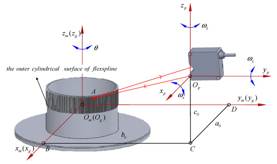
Figure 1.
Mapping relationship between coordinates.
Assuming the rotation angle of the gear is , then the mathematical expression for the spatial coordinates of any measured point A captured by the sensor in the system is as follows:
where is the distance from the measured point A captured by the PLS to the midpoint of the flexspline face width and is the radius of the root circle.
According to the mapping relationship, the mathematical expression for transforming the measured point A from the machine coordinate system to the spatial coordinates in the sensor coordinate system is as follows:
In the gear coordinate system, the mathematical expression for the spatial coordinates of the measured point A is as follows:
where is the face width, is the pressure angle, is the rotation angle of the gear, and , , and are the offset distances of the PLS in the tangential, radial, and axial directions in the gear coordinate system, respectively. Sensor measurements are also influenced by pitch angle, yaw angle, and rolling angle between the light emitted by the PLS and the machine coordinate system. To determine the coordinates of the measured point A, it is necessary to calibrate the position of the sensor to determine the six position parameters. is the spatial transformation matrix that converts the tooth flank from the machine coordinate system to the gear coordinate system, and is related to the measured value of the sensor, the position of the sensor, and the nominal distance of the sensor.
2.2. Calibration of Sensor Pose Parameters
To determine the six pose parameters , , , , , and of the emitted light of the PLS in the machine coordinate system, it is necessary to perform several calibrations using the geometric features of the flexspline outer cylindrical surface.
- (1)
- Calibration of pitch angle . As shown in Figure 2, the sensor measuring point needs to be adjusted to . To accomplish this, the pitch angle of the PLS needs to be fine-tuned so that the emitted light from the sensor shines on the outer cylindrical of the flexspline and remains within the effective range of the sensor. Next, a set of measurements on the outer cylindrical of the flexspline must be obtained. Finally, the turning point in the measurements needs to be found; this is where the values change from large to small and then back to large and stop at the minimum value . At this point, the sensor’s pose around the axis has been adjusted to the calibrated zero position.
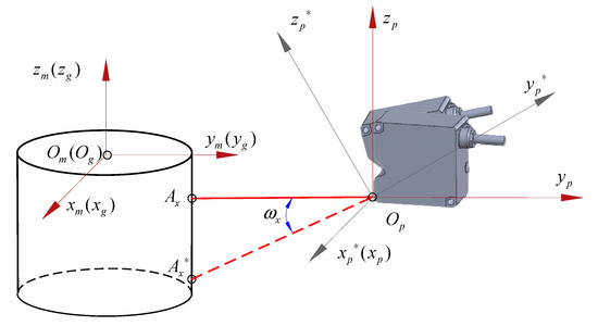 Figure 2. Calibration of pitch angle .
 - (2)
- Calibration of roll angle . The emitted light from the PLS is identified as the axis, and the roll angle will not affect the measurement results.
- (3)
- Calibration of yaw angle . As shown in Figure 3, the sensor measurement point needs to be adjusted to . The yaw angle of the PLS is fine-tuned so that the measurement point shines on the outer cylinder of the flexspline and remains within the effective range of the sensor. Next, a set of measurements on the outer cylindrical of the flexspline is obtained. Finally, the turning point in the measurements is found; this is where the values change from large to small and then back to large, and stop at the minimum value . At this point, the sensor’s pose around the axis has been adjusted to the calibrated zero position.
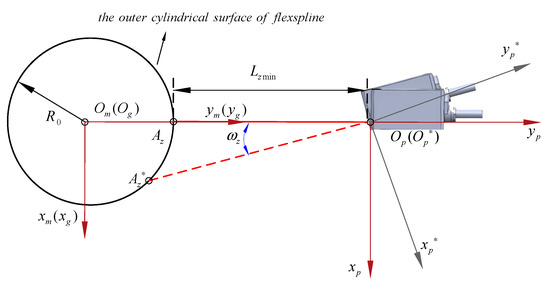 Figure 3. Calibration of the yaw angle .
 - (4)
- Calibration of offset distances , and . As shown in Figure 4, the sensor moves along the direction and captures the highest point position of the arc. At this moment, the sensor obtains a set of measurements on the outer cylinder of the flexspline. The smallest value in the measuring value is marked as and then the sensor is moved along the direction to the offset position. At this time, the sensor’s readings are , and is marked, where is the radius of the flexspline outer circle. Since the position of the measured point in the direction of the axis has no influence on the calibration results. the initial offset distance in that direction may not be calibrated and can be set to . Based on geometric relationships, the expressions for the offset distances and of the sensor are as follows:
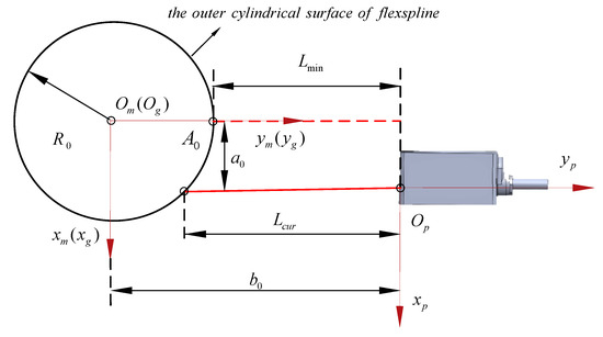 Figure 4. Calibration of sensor offset distances.
2.3. Reconstruction of Tooth Flank
The sensor emits light on a point of a tooth flank of the flexspline, and this point is called the measured point. The offset distances of the sensor along the tangential, radial, and axial directions of the flexspline are , , and , respectively. The mathematical expression for the spatial coordinates of the measured point in the gear coordinate system is as follows:
The matrix and the parameter are satisfied:
where is the coordinate transformation matrix that converts the flexspline tooth information from the machine coordinate system to the gear coordinate system, is the measured value of the sensor at a defined position, and is the nominal distance of the sensor. H is the Y coordinate value of the measured point in the machine coordinate system.
At this point, the teeth flanks of the measured flexspline can be reconstructed in the gear coordinate system based on the measurement data using Equation (5).
3. Simulation Experiment
In order to verify the correctness of the proposed method, a simulation experiment is carried out. The experiment is divided into three parts: Firstly, a virtual model of the teeth flanks is established. Secondly, a simulation experiment and tooth flank reconstruction are carried out to obtain the virtual measurement data of the offset PLS; the virtual measurement data is utilized to reconstruct the teeth flanks of the measured gear in reverse. Finally, the reconstructed teeth flanks are compared with the virtual theoretical teeth surface obtained previously.
3.1. Creation of Virtual Tooth Flanks
The virtual teeth flanks are created according to the parameters in Table 1.

Table 1.
Simulation gear parameters.
The position of any point on a tooth flank can be determined by the two parameters , where is the position along the face width and is the transverse pressure angle. When considering the rotation of the tooth flank with the gear around the axis, it is necessary to represent the rotated angle by another parameter . According to the above definition, given a set of parameters , it is possible to uniquely determine a point on the tooth flank at a given moment. The ranges of these three parameters are as follows: , , and . Here, is the face width, and is the transverse pressure angle at the tip circle.
The equation of the involute is:
The equation of the left tooth flank is:
The equation of the right tooth flank is:
where the parameter is the current position along the face width. The teeth flanks generated by Equations (8)–(10) according to the parameters in Table 1 are shown in Figure 5.
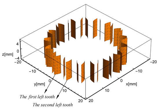
Figure 5.
Simulated gear tooth flanks.
3.2. Virtual Measurement and Reconstruction of Teeth Flanks
In order to obtain virtual measurement data of sensors (during virtual measurement), the initial positions of the sensor and the virtual gear are set according to the pose relationship between the PLS and the measured gear, where the gear axis coincides with the axis of the coordinate system, the sensor is located in the first quadrant, and the nominal distance is . In order to reduce the influence of the incident angle of the light as much as possible, to ensure the density of the sampling of a tooth flank, and to enhance the reliability of the tooth flank information, the tangential offset distance can be 1/2 of the radius of the base circle, i.e., the offset distance of the PLS along the tangential direction is , and the sensor offset distance along the radial direction is . The simulated gear rotates with the spindle of the instrument, while the PLS is set at the initial position and maintains a constant pose. The measuring light is shone on a tooth flank of the measured gear, scanning sequentially through the measurable area of each tooth flank. The measurement process is shown in Figure 6.
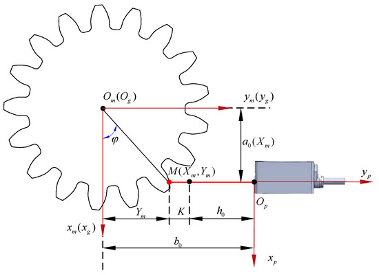
Figure 6.
Virtual measurement.
After the gear rotates by an angle and the sensor is illuminated on the measured point M, the left tooth pressure angle is calculated, which satisfies the following equation:
Substituting the sensor offset distance and the left tooth flank Equation (9) into Equation (11), i.e.,
can be found from Equation (12), where pressure angle .
Substituting pressure angle and angle into Equation (13), the coordinate of the current measured point M in the Y direction is:
According to Equation (13), the current sensor measurement value can be calculated:
From Equations (13) and (14), the coordinates of the intersection point of the measuring light ray and the left tooth flank, (i.e., the current sampling point) and the current sensor measurement value can be obtained in the coordinate system.
Following the above method, during the 360° rotation of the gear, the coordinates of any current sampling point in the measurement area on the tooth flank and the corresponding measuring value of the PLS can be calculated.
Taking , a number of sample points of the left tooth flank can be obtained. Using these sampling points, the reconstructed left tooth flank can be obtained from the tooth flank reconstruction principle in Section 2.3. Similarly, the reconstructed right tooth flank can be obtained.
The simulated measured data are shown in Figure 7. The reconstructed teeth flanks are shown in Figure 8. In the experiments, the slopes of the lines of the simulated measured data in Figure 7 are related to the selected offset distances, with larger offset distances resulting in smaller slopes.
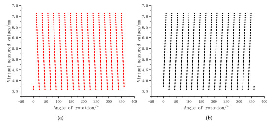
Figure 7.
Virtual measurement data of sensors. (a) Virtual measurement data for the left teeth flanks. (b) Virtual measurement data for the right teeth flanks.
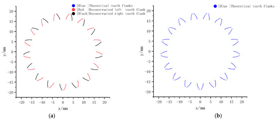
Figure 8.
Reconstructed teeth flanks and theoretical teeth flanks. (a) Reconstructed and theoretical teeth flanks. (b) Theoretical teeth flanks.
3.3. Comparison and Analysis of Results
The theoretical left and right teeth flanks of the virtual gear and the reconstructed left and right teeth flanks based on the virtual measurements are shown in Figure 8, where the theoretical teeth flanks are in blue, the reconstructed left teeth flanks are in red, and the reconstructed right teeth flanks are in black. In Figure 8a, the theoretical teeth flanks are covered by the reconstructed teeth flanks. Since the theoretical teeth flanks generated in step 1 and the reconstructed teeth flanks in step 2 overlap completely, only red and black lines are visible in Figure 8a. The simulation experiment results show that the reconstructed teeth flanks based on the proposed method match perfectly with the measuring area on the theoretical teeth flanks, which verifies the correctness of the gear surface measurement model in the gear point laser measurement.
4. Measurement Experiment
4.1. Experiment Devices
In order to validate the effectiveness of the rapid measurement method of flexspline pitch using offset PLS, a measurement system is established as shown in Figure 9. The rotation angle of the air-bearing rotary table is read by two read-heads installed in opposite diameter directions. The PLS is mounted on a fine-tuning stage that allows movement of the sensor across and rotation around three linear axes. The measured flexspline is mounted on the instrument spindle. Time is used as the trigger source of the sensor for data acquisition.
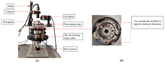
Figure 9.
Experimental setup. (a) Experimental setup diagram. (b) Partial schematic diagram.
The PLS is the Keyence LK-H020 sensor (Osaka, Japan). According to the specification of LK-H020, the nominal distance h0 is equal to 20 mm, the measurement range is ±3 mm, the repeatability is 0.02 µm, and the diameter of the light point is Φ25 µm. After experiments, it was found that when the angle of incidence and reflection exceeds 65°, the PLS will receive no or very little reflected light, which is the limit of the sensor’s data acquisition capability.
The measured flexspline parameters are shown in Table 2.

Table 2.
Parameters of the flexspline.
4.2. Procedure and Results
In the experiment, the sensor’s poses were first calibrated according to the process in Section 2.2 of this paper. After calibration, the pitch, rolling, and yaw angles were considered to be adjusted in place, and solved for the offset distances as follows: = 11.044 mm, = 38.869 mm, and set = 0 mm.
During the measurement process, the spindle rotates and the laser light emitted by the PLS scans the teeth flanks of the gear, obtaining the angular position of the tested gear and the measurement value of the sensor. At a specific cross-section of the flexspline, because the PLS is positioned at a particular offset distance in the tangential direction, it can only capture valid point data from one side of the measured flexspline’s teeth flanks for each rotation of the spindle. Consequently, to acquire information about both the left and right teeth flanks of the flexspline, the PLS must be moved to a new offset distance after obtaining the profile information of the teeth flanks at the offset distance . Through this process, information about both the left and right teeth flanks of the flexspline in a particular cross-section can be obtained.
The left tooth flank data measured by the PLS is shown in Figure 10. It can be seen that in the region near the root of the tooth flank, there are some “scattered points”. This is due to the steepness of the root part of the tooth changing, making the distance between the teeth smaller, resulting in phenomena such as multiple reflections in the gear’s root area. The smaller the gear modulus and the greater the number of teeth, the more scattered points appear in the region near the gear root.
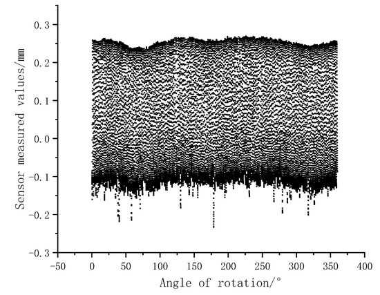
Figure 10.
Data of tooth flank measured by PLS.
In Figure 10, due to the smaller angle between the incident and reflected angles in the tooth tip and root regions, the data obtained by the sensor are denser; whereas in the tooth flank region, the angle between the incident and reflected angles is larger, resulting in sparser data obtained by the sensor.
The fluctuations in the upper envelope of the data in Figure 10 are due to the presence of roundness errors in the flexspline.
In Figure 10, the fluctuations in the measured data are mainly caused by the sampling points being located at different positions of the gear surface.
As shown in Figure 11, under the offset condition, as the gear rotates, the sampled points from the sensor may fall into one of four regions. The measurement data is invalid when the sampling point is in zone IV (where the measuring light of the PLS is obscured). In addition, the actual measurement light ray has a certain diameter (about 0.025 mm), which can lead to a transition state in the measurement distance when part of the light hits the gear’s root and the other part hits the gear’s tip, resulting in invalid points.
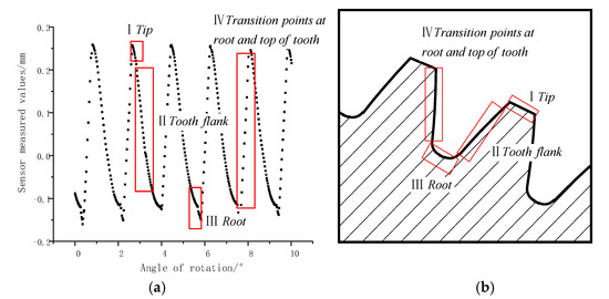
Figure 11.
Description of the measurement area. (a) Measuring area of the flexspline gear surface. (b) Measuring position of the flexspline gear surface.
The teeth flanks of the flexspline after reconstruction of the teeth flanks based on the measured sampling data are shown in Figure 12. The time taken by a conventional gear measurement center to measure the flexsplines may vary from a few minutes to even several hours, while the time taken to measure the flexspline by the proposed instrument is under 15 s.
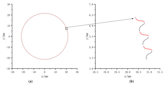
Figure 12.
Reconstruction of teeth flank data. (a) reconstructed teeth flanks of flexspline. (b) partially reconstructed teeth flanks of flexspline.
4.3. Comparison with Other Instruments
In order to verify the correctness of the evaluation results, the flexspline surfaces obtained by the proposed method and the video measuring method are compared and analyzed, as shown in Figure 13, where the teeth flanks obtained by the video measuring method are in blue, the left teeth flanks reconstructed by the proposed method are in red and the right teeth flanks reconstructed by the proposed method are in black. It can be seen that the gear surfaces measured using the proposed method are largely the same as those measured by the video measuring method, with slight differences in detail. These minor discrepancies may be caused by the following factors: inaccurate calibration of the sensor pose parameters, the linearity of the sensor not being calibrated precisely, and the influence of the angle of incidence.

Figure 13.
Comparison of reconstruction of teeth flank data with teeth flank data obtained by video measuring method. (a) Overall comparison of video measuring method with reconstructed teeth flanks. (b) Partial comparison of the video measuring method with the reconstructed teeth flanks. (c) Partially reconstructed teeth flanks.
4.4. Repeatability of Pitch Measurements
In this experiment, the tooth pitch deviation is evaluated using the tooth profile of the left flank of the flexspline. The results of five measurements of single pitch deviation [3] and total cumulative pitch deviation [3] of the left teeth flanks are shown in Figure 14. The single pitch deviation is 34.57 µm and the total cumulative pitch deviation is 63.69 µm (shown in Table 3). As shown in Figure 15, the repeatability of single pitch deviation or cumulative pitch deviation measurements is within ±3 µm. The pitch deviation results obtained by the proposed method show good repeatability, indicating that the measurement method has good stability and reliability and can reflect the true state of the flexspline teeth flanks. It should be noted that after the sensor has been fully warmed up, when measuring stationary objects at vertical incidence, the measured data jumps by about ±0.625 µm, which is one of the sources of repeatability errors in the measured data.
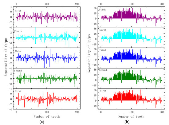
Figure 14.
Single pitch deviations and total cumulative pitch deviations of 5 time measurements. (a) single pitch deviations. (b) total cumulative pitch deviations.

Table 3.
Tooth pitch deviation (unit: µm).
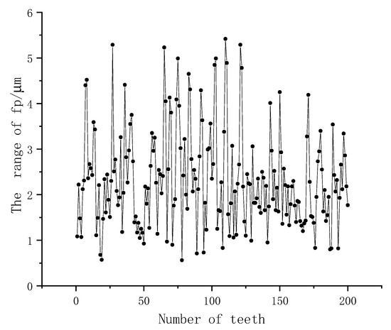
Figure 15.
The range of individual single pitch deviation in the repeated measurements.
5. Conclusions
Flexsplines are core components of harmonic gear reducers. In order to efficiently evaluate the quality of flexsplines in a harmonic gear reducer and reduce the influence of the incidence angle of the PLS’s emitted light, a rapid measurement method for flexspline pitch deviations using offset PLS is proposed.
- (1)
- This paper investigates the principle of measuring the teeth flanks of a flexspline by offsetting the PLS and establishes spatial transformation relationships between the machine coordinate system, the gear coordinate system, and the sensor coordinate system. By constructing an expression for the point laser 3D measurement model of the teeth flanks of a flexspline, the proposed method realizes the reconstruction of the teeth flanks of a flexspline, improving the sampling density in the middle area of the surface of a tooth and reducing the influence of the incidence angle of the PLS’s emitted light.
- (2)
- In order to calibrate the spatial pose of the sensor in gear measurement, a simple method for calibrating the spatial pose of the sensor using the geometrical features of the outer cylindrical of the flexspline to determine its six pose parameters is proposed. By this method, the repeatability and accuracy of measurements can be effectively improved. The calibration results of the sensor’s pose have a direct influence on the accuracy of the measurements.
- (3)
- An evaluation of the pitch deviation of the reconstructed flexspline is carried out, and the repeatability and accuracy of the results are good, and the obtained gear surfaces of the flexspline are largely the same as those obtained using the video measuring method. The repeated measurements are carried out for five revolutions, and the repeatability of the obtained individual pitch deviation and the total accumulated pitch deviation are within ±3 µm. In addition, the measurement time for a flexspline using the proposed method is under 15 s.
Experiments have demonstrated that this method yields rapid acquisition of tooth surface data, with easy operation and low overall hardware costs. At the same time, there are still some shortcomings in this method and experiment: (1) the optimal offset distance of the PLS has not yet been determined, and (2) the calibrated sensor pose parameters have not been sufficiently examined. Further research and validation through more experiments are needed in the future.
Author Contributions
Conceptualization, X.W. and K.Z.; methodology, X.W. and K.Z.; software, X.W. and K.Z.; validation, X.W. and K.Z.; formal analysis, X.W., K.Z. and L.X.; investigation, X.W., C.Z. and K.Z.; resources, X.W., C.Z., L.X., K.Z., M.L., D.Z., Z.S. and T.Y.; data curation, X.W. and K.Z.; writing—original draft preparation, X.W. and K.Z.; writing—review and editing, X.W. and K.Z.; visualization, X.W. and K.Z.; supervision, X.W. and K.Z.; project administration, X.W. All authors have read and agreed to the published version of the manuscript.
Funding
This research was funded by the National Natural Science Foundation of China (52227809, 51775172).
Data Availability Statement
The data that support the findings of this study are available from the corresponding author upon reasonable request.
Conflicts of Interest
The authors declare no conflicts of interest.
References
- Goch, G.; Guenther, A.; Peng, Y.; Ni, K. Gear metrology—An update. CIRP Ann. Manuf. Technol. 2023, 72, 725–751. [Google Scholar] [CrossRef]
- Huang, G.Y.; Bai, J.; Feng, F.; Zeng, L.; Feng, P.F.; Li, X.H. A Hybrid Strategy for Profile Measurement of Micro Gear Teeth. Micromachines 2023, 14, 1729. [Google Scholar] [CrossRef]
- IS0 1328-1; Cylindrical Gears-Iso System of Flank Tolerance Classification—Part 1 Definitions and Allowable Values of Deviations Relevant to Flanks of Gear Teeth. ISO: Geneva, Switzerland, 2013.
- Yu, B.; Li, Z.G.; Sun, Y.Q.; Shi, Z.Y. A method combining laser and vision detection for on-line measurement of small modules gears. Meas. Sci. Technol. 2024, 35, 055014. [Google Scholar] [CrossRef]
- Tao, J.Y.; Zhou, J.; Wang, S.L.; Dong, J.P.; Ma, C.; Xiao, Y.L.; Xia, M.H. An efficient and accurate measurement method of tooth flank variations for face gears. Measurement 2023, 221, 113486. [Google Scholar] [CrossRef]
- Goch, G.; Ni, K.; Peng, Y.; Guenther, A. Future gear metrology based on areal measurements and improved holistic evaluations. CIRP Ann. Manuf. Technol. 2017, 66, 469–474. [Google Scholar] [CrossRef]
- Yin, P.L.; Han, F.B.; Wang, J.H.; Lu, C.X.; Du, H.B. Influence of coordinate system establishment error on tooth profile deviation measured by standard polar coordinate method on gear measuring center. Measurement 2022, 187, 110344. [Google Scholar] [CrossRef]
- Li, T.X.; Li, Y.L.; Deng, X.Z.; Li, J.F. A measurement method for tooth surface errors of straight bevel gears based on 3D model. Meas. Sci. Technol. 2021, 32, 025011. [Google Scholar] [CrossRef]
- Pillarz, M.; von Freyberg, A.; Fischer, A. Gear Shape Parameter Measurement Using a Model-Based Scanning Multi-Distance Measurement Approach. Sensors 2020, 20, 3910. [Google Scholar] [CrossRef]
- Mazur, T.; Rucki, M.; Gutsalenko, Y. Accuracy Analysis of the Curved Profile Measurement with CMM: A Case Study. Facta Univ.-Ser. Mech. Eng. 2023, 21, 121–135. [Google Scholar] [CrossRef]
- Pillarz, M.; von Freyberg, A.; Stöbener, D.; Fischer, A. Gear Shape Measurement Potential of Laser Triangulation and Confocal-Chromatic Distance Sensors. Sensors 2021, 21, 937. [Google Scholar] [CrossRef]
- Auerswald, M.M.; von Freyberg, A.; Fischer, A. Laser line triangulation for fast 3D measurements on large gears. Int. J. Adv. Manuf. Technol. 2019, 100, 2423–2433. [Google Scholar] [CrossRef]
- Urbas, U.; Zorko, D.; Cerne, B.; Tavcar, J.; Vukasinovic, N. A method for enhanced polymer spur gear inspection based on 3D optical metrology. Measurement 2021, 169, 108584. [Google Scholar] [CrossRef]
- Alaci, S.; Ciornei, F.C.; Romanu, I.C.; Doroftei, I.; Bujoreanu, C.; Tamasag, I. A Rapid and Inexpensive Method for Finding the Basic Parameters of Involute Helical Gears. Appl. Sci. 2024, 14, 2043. [Google Scholar] [CrossRef]
- Guo, X.Z.; Shi, Z.Y.; Yu, B.; Zhao, B.Y.; Li, K.; Sun, Y.Q. 3D measurement of gears based on a line structured light sensor. Precis. Eng.-J. Int. Soc. Precis. Eng. Nanotechnol. 2020, 61, 160–169. [Google Scholar] [CrossRef]
- Shang, Z.Y.; Wang, J.H.; Zhao, L.; Du, H.B.; Yin, P.L.; Zhang, Y.D. Measurement of gear tooth profiles using incoherent line structured light. Measurement 2022, 189, 110450. [Google Scholar] [CrossRef]
- Zhang, S.S.; Yang, H.T.; Liu, Y.Q. Spatial error modeling and accuracy distribution of line laser gear measuring center. Meas. Control 2024, 57, 280–290. [Google Scholar] [CrossRef]
- Wang, T. Research on Three-Dimensional Measurement Method for Gears Based on Line Structured Light. Ph.D. Thesis, Beijing University of Technology, Beijing, China, 2021. [Google Scholar]
- Sun, Y.Q.; Shi, Z.Y.; Yu, B.; Li, H.B. Incident angle model of measuring light in gear measurement utilizing a line laser sensor and analysis on its influence factors. Measurement 2022, 203, 111838. [Google Scholar] [CrossRef]
- Tian, H.; Wu, F.; Gong, Y.J. Gear Tooth Profile Reconstruction via Geometrically Compensated Laser Triangulation Measurements. Sensors 2019, 19, 1589. [Google Scholar] [CrossRef]
- Härtig, F.; Stein, M. 3D involute gear evaluation—Part I: Workpiece coordinates. Measurement 2019, 134, 569–573. [Google Scholar] [CrossRef]
- Shang, Z.Y.; Wang, J.H.; Du, H.B.; Yin, P.L. High-precision measurement of gear tooth profile using line spectral confocal method. Measurement 2023, 223, 113779. [Google Scholar] [CrossRef]
- Fang, S.P.; Zhu, X.D.; Yang, P.C.; Cai, Q.W.; Komori, M.; Kubo, A. Analysis and compensation method for installation error in measuring gear tooth flank with laser interferometry. Opt. Eng. 2014, 53, 084111. [Google Scholar] [CrossRef]
- Urbas, U.; Hrga, T.; Povh, J.; Vukasinovic, N. Novel alignment method for optical 3D gear metrology of spur gears with a plain borehole. Measurement 2022, 192, 110839. [Google Scholar] [CrossRef]
Disclaimer/Publisher’s Note: The statements, opinions and data contained in all publications are solely those of the individual author(s) and contributor(s) and not of MDPI and/or the editor(s). MDPI and/or the editor(s) disclaim responsibility for any injury to people or property resulting from any ideas, methods, instructions or products referred to in the content. |
© 2024 by the authors. Licensee MDPI, Basel, Switzerland. This article is an open access article distributed under the terms and conditions of the Creative Commons Attribution (CC BY) license (https://creativecommons.org/licenses/by/4.0/).