Abstract
Ultrasonic elliptical vibration-assisted cutting (UEVC) has been successfully applied in the precision and ultra-precision machining of hard and brittle materials due to its advantages of a low cutting force and minimal tool wear. This study developed a novel double-excitation ultrasonic elliptic vibration-assisted cutting (D-UEVC) device by coupling ultrasonic vibrations in orthogonal dual paths. A two-degree-of-freedom vibration system of the D-UEVC was modeled, form which the elliptical trajectory of the end under different phase angle φ values was derived. The initial dimensions of the D-UEVC device were obtained through theoretical calculations. Subsequently, with the aid of finite element analysis methods, structural dynamic analysis of the device was conducted to obtain the elliptical vibration trajectory under different phase differences of the excitation source. In order to verify the cutting trajectory and cutting performance of the D-UEVC device, a prototype of the device was developed, and a series of vibration performance tests as well as the Inconel 718 cutting experiment were conducted. The experimental results illustrated that the D-UEVC device can achieve the elliptical vibration trajectory at the tool tip with a resonant frequency of 36.5 KHz. The adjustable elliptical vibration trajectories covered a range of ±4 μm in the axial and radial directions. Compared with the surface roughness Ra = 0.36 μm under the conventional cutting, the surface roughness of Inconel 718 under D-UEVC was Ra = 0.215 μm. Thus, the surface quality can be significant improved by utilizing the D-UEVC device.
1. Introduction
The ultrasonic elliptical vibration cutting method was first proposed by Shamoto [1]. This method applies ultrasonic elliptical vibration to the tool, resulting in periodic contact and separation between the tool and workpiece during machining. Research has shown that by virtue of its separation characteristics, UEVC can prevent continual contact friction between the tool and the processed surface. As a result, UEVC is capable of effectively reducing damage to the processed surface, facilitating the efficient penetration of cutting fluids into the cutting zone and minimizing friction between the tool and the processed surface [2]. Thus, UEVC can effectively reduce cutting forces [3,4,5,6] and cutting heat [7,8], thereby improving the surface quality of workpieces [9,10,11,12,13] while significantly extending the lifespan of the tool [12,14,15]. It is particularly suitable for precision and ultra-precision machining of hardened steel [1,16], ceramics [17,18], silicon carbide [19,20], tungsten carbide [21,22], and other hard and brittle materials.
At present, UEVC devices can be classified into single-excitation UEVC devices and multi-excitation UEVC devices. The single-excitation UEVC device is structurally simple and easy to control; however, the operating frequency is singular, the synthesized elliptical trajectory is non-adjustable, and the amplitude is very small. In contrast, the multi-excitation UEVC device can generate different shapes of elliptical trajectories in different working conditions by adjusting the phase difference between excitations [23]. A resonant-mode two-dimensional motion generator (TMG) consisting of two sets of 60°-angled core-type ultrasonic transducers was proposed by Guo et al. [24]; a three-stage motion component was added to the tool tip to achieve the required elliptical trajectory. Kurniawan et al. [25] proposed the Ultrasonic Elliptical Motion Transducer (UEMT) comprising two Langevin transducers and set at a 90° angle. The symmetrical and asymmetrical vibration modes with a resonance frequency of 24 KHz can be achieved by UEMT: particularly, a vertical amplitude of 1.4 µm and a horizontal amplitude of 0.6 µm for the elliptical trajectory can be realized under a 90-degree phase difference. An analytical method for calculating the resonant frequency and mode for ultrasonic elliptical vibration devices was proposed by Yang et al. [26]. Based on the analytical method, a gantry-frame structural ultrasonic elliptical vibration tool was developed. This analytical method can not only be used for the design of elliptical vibration cutting tools based on coupled resonance vibration, but also has important significance for the dynamic analysis of vibration-assisted cutting machine tools. Pi et al. [27,28] presented an orthogonal UEVC device based on wave transmission technology. The device has a simple structure and high coupling efficiency, and the elliptical trajectory deviation of the tool tip can be achieved by adjusting the phase difference. Kang [29] designed an ultrasonic elliptical vibration cutting device with multi-stage amplification comprising two longitudinal vibration transducers. The device operates in a dual bending vibration mode by exciting the longitudinal vibration transducers in the x and z directions of the bending amplitude horn. The tool synthesizes ultrasonic elliptical vibration by adjusting the phase difference between the two excitations.
In pursuit of an elliptical vibration device that possesses a compact size and flexibly adjustable elliptical trajectory shape, in this study, a novel double-excitation ultrasonic elliptic vibration-assisted cutting (D-UEVC) device that couples ultrasonic vibrations in orthogonal dual paths is proposed based on the mechanical vibration theory. It can adjust the elliptical trajectory at the tool tip by adjusting the excitation voltage and phase difference between the two paths. Firstly, an equivalent two-degree-of-freedom vibration system model is established, theoretically proving the feasibility of generating the elliptical trajectory. Based on the model and Langevin equation, the initial dimensions of the device are determined. The vibration characteristics of the D-UEVC device under different parameters are analyzed using the finite element analysis method. Finally, a prototype of the D-UEVC device is manufactured, and a series of vibration performance tests and cutting performance experiments are conducted to validate the correctness of the theoretical modeling and simulation results, laying a foundation for the subsequent development of ultrasonic elliptical vibration cutting devices.
2. Design of D-UEVC Device
2.1. Mechanistic Analysis of Double Excitation Elliptical Vibrations
Due to the minimal mutual interference and the highest decoupling efficiency when the angle between two sets of vibrating waves in two-dimensional space is 90° [30], the two branches of the D-UEVC device considered in this study are arranged with a 90° angular layout, as shown in Figure 1. The ultrasonic vibrating waves generated by four pieces of PZT are delivered by an exponential amplitude horn. An elliptical trajectory occurs at the end effector when the ultrasonic vibration of the two branches is transmitted to the end effector [31].
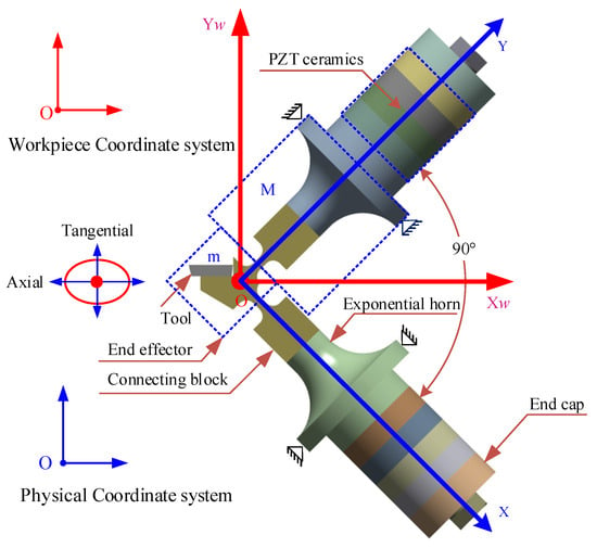
Figure 1.
Structure of D-UEVC.
Based on the considerations above, an equivalent two-degree-of-freedom vibration system model is constructed, as depicted in Figure 2. In this model, points F1, F2 represent the initial vibration positions in the fixed node plane; P1 and P2 are the output points at the ends of the ultrasonic amplitude horns; and O is the vibration output point of the end actuator. The equivalent stiffness k1 and equivalent damping c1 correspond to the properties of the structural connecting column; k2 and c2 represent the equivalent stiffness and damping of the chamfered straight-beam flexible hinge. The equivalent stiffness kL and damping cL represent the load stiffness and damping of the single branch in the X and Y directions, respectively. The mass m is equal to the total mass of the end effector; the mass M is composed of the mass M1 of the amplitude horn and the mass M2 of the connecting block.
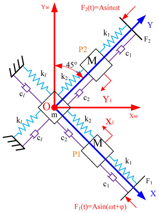
Figure 2.
Model of two-degree-of-freedom vibration system.
In vibration analysis, the responses at P1 and P2 to the longitudinal vibrations F1(t) and F2(t) can be expressed as follows:
where .
Therefore, the two equivalent vibration excitations in the X and Y directions at the output end O of the end effector are as follows [32]:
Assume that the load stiffness and damping of the single branch in the X and Y directions are equal to each other. The steady-state response at the output end O of the end effector is expressed as follows:
where .
According to the relationship between the workpiece coordinate system and the physical coordinate system in Figure 2, the steady-state vibration response of the end effector in the workpiece coordinate system can be written as follows:
If we ignore the influence of the phase parameter and delay on the vibration response, the ellipse equation in the workpiece coordinate system can be obtained as follows:
The analysis of the vibration response of the ultrasonic transducer reveals that the phase difference becomes a critical parameter affecting the output elliptical vibration trajectory of the end effector. When the phase difference is 0°or 180°, the vibration trajectory approximates a straight line. For phase differences of 0°–180°, the vibration trajectory forms an ellipse. Figure 3 illustrates the tool tip’s elliptical vibration trajectories formed by different phase differences without considering phase delay errors.
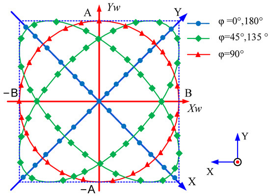
Figure 3.
Elliptical trajectory under different phase angle φ values.
2.2. The Structure of the UEVC Device
Based on the theoretical analysis presented above, in this study, two sets of longitudinal vibration transducers are arranged at a 90° angle to generate ultrasonic vibrations in the X and Y directions. The longitudinal vibration transducer consists of main components such as the end effector, exponential half-wavelength amplitude horn, PZT, rear cover plate, and preloading bolts (Figure 4). The detailed characteristics of the material are listed in Table 1.
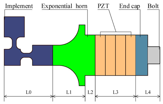
Figure 4.
Longitudinal vibration transducers.

Table 1.
Material parameters of longitudinal vibration transducer.
The working frequency is set at 36.5 kHz, and the dimensions of each component of the longitudinal vibration transducer are determined by the following equations based on the Rayleigh equation for the half-wavelength amplitude horn calculation [33]:
where c0 represents the velocity of sound in PZT-8, c1 is the velocity of a wave in stainless steel, c2 denotes the velocity of a wave in the amplitude horn, and f represents the natural frequency. ρ0 is the density of PZT-8 ceramic, ρ1 is the density of the amplitude horn, A0 corresponds to the surface area of PZT-8 ceramic, and A1 represents the surface area of the amplitude horn. Based on these equations, the dimensions of the D-UEVC device are obtained, as shown in Table 2.

Table 2.
Structure parameter of longitudinal vibration transducer.
3. Structural Dynamics Analysis of D-UEVC
3.1. Modal Analysis of D-UEVC
Modal analysis is an essential component of structural dynamics analysis, as it can reveal the resonant frequencies and mode shapes of a structure, thereby providing necessary theoretical support for an in-depth investigation of the dynamic characteristics of the D-UEVC device and subsequent design. Firstly, the three-dimensional model of the device is imported into ANSYS for analysis, with the material properties of each component detailed in Table 1. The flange face is selected as the fixed constraint, and a tied contact method is used for each contact surface. The mesh has a moderate quality, with an element size of 2 mm, a total of 12,444 elements, and 32,393 nodes, as depicted in Figure 5. The results of the modal analysis, shown in Figure 6a,b, indicate that the device’s primary resonant frequency is around 36,553 Hz, at which point the device exhibits axial reciprocating motion.
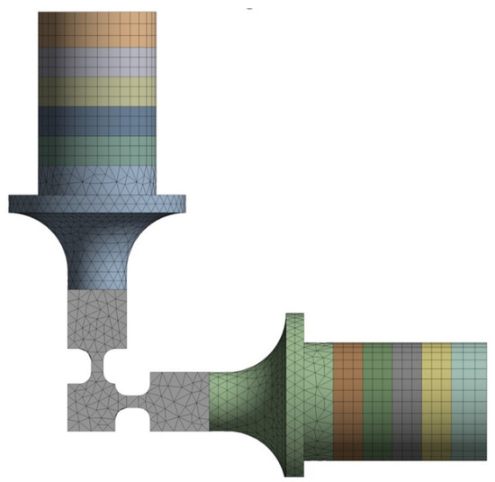
Figure 5.
Finite element model of the D-UEVC device.
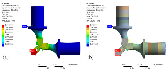
Figure 6.
(a) Fourth-order vibration frequency. (b) Vector plot of vibration mode displacement.
3.2. Response Analysis of D-UEVC
To investigate the influence of different phase differences on the elliptical trajectory output of the D-UEVC device, harmonic response analysis of the D-UEVC device was carried out by finite element analysis. Four sets of excitation signals were established in the two branches of the ultrasonic elliptical vibration system. Each set of signals comprises two identical amplitude sinusoidal signals with varying phase differences, specifically set at 45°, 90°, 135°, and 180°, at a frequency of 36,486 Hz. Vibrational displacement data in the X and Y directions at the tip were computed and obtained at this frequency for the four phase difference sets. Subsequently, the motion trajectory at the end of the actuator was determined using MATLAB R2022a. The specific results are illustrated in Figure 7. When the phase difference between the two signals is 0°, the trajectory approximates a straight line, and the actuator end executes linear reciprocating motion. As the phase difference increases from 0° to 90°, the elliptical shape transitions from flat to full. Furthermore, the minor axis of the ellipse gradually enlarges, while the angle with the Z-axis decreases to 0°. Simultaneously, as the shape of the ellipse evolves, the angle between its major axis and the X-axis decreases progressively towards zero. When the phase difference of the two sinusoidal excitations increases from 90° to 180°, the ellipse gradually flattens, the minor axis diminishes, and the angle with the positive Z-axis increases. Moreover, the angle between the major axis of the ellipse and the positive X-axis also enlarges gradually. Therefore, structural dynamic analysis demonstrates that the D-UEVC device can achieve the desired elliptical trajectory by adjusting the phase difference of the excitation signals.
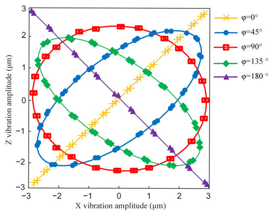
Figure 7.
The elliptical trajectory under different phase angle φ values.
4. Experimental Validation of D-UEVC Devices
Based on the theoretical and structural dynamic analysis, the prototype of the D-UEVC device was successfully developed in this study, as shown in Figure 8, comprising two one-dimensional vibration transducers arranged at a 90° angle. As the working frequency and elliptical vibration trajectory are crucial parameters determining the processing performance of the UEVC device, an in-depth investigation into the impedance and vibration characteristics of the dual-excitation UEVC device was conducted with the aim of achieving the desired elliptical vibration trajectory in practical applications.
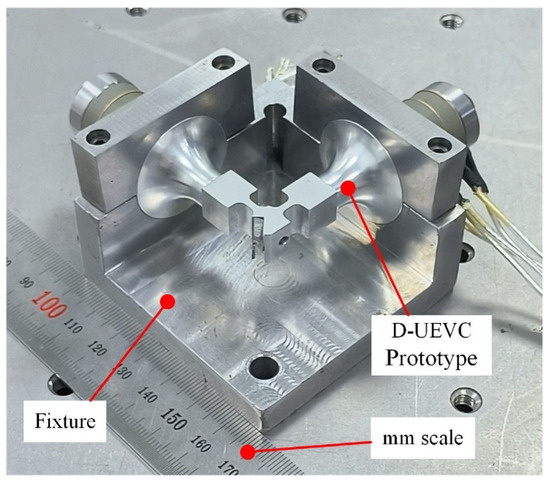
Figure 8.
Prototype of the D-UEVC device.
4.1. Impedance Characterization Experiment
The D-UEVC device presented in this paper was developed based on piezoelectric transducers, which exhibit unique impedance characteristics at different frequencies. Conducting an impedance characteristic test on the device is an effective method to obtain the operating frequency of the device. The PV70A impedance analyzer was used for the experimental test. The impedance analysis parameters were set as follows: the frequency measurement ranges were 34–44 kHz and 31.6–43.6 kHz, respectively, and the calculation step was automatic step. The test results were directly obtained by connecting the impedance analyzer to a computer, as depicted in Figure 9.
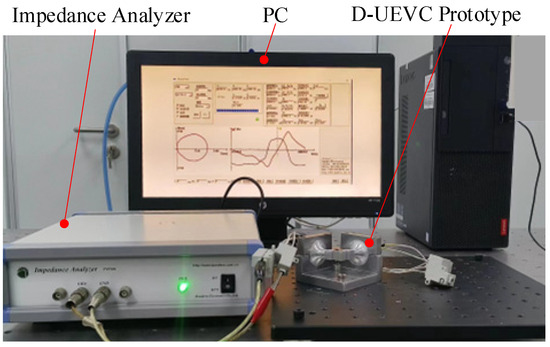
Figure 9.
Impedance characteristics testing of D-UEVC.
The impedance characteristic test results, shown in Figure 10, indicate that both branches of the D-UEVC device have a resonant frequency of 36.5 kHz, with a mechanical quality factor Qm of 802, a dynamic resistance R1 of 48 Ω, and a free capacitance CT of 10nF. Additionally, the admittance circle forms a complete circle. These test results indicate that the device exhibits favorable vibration characteristics.
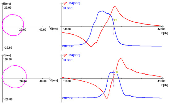
Figure 10.
The impedance curve of both branches.
4.2. Vibration Trajectory Measurement
The schematic diagram of the elliptical trajectory testing system is shown in Figure 11a. The excitation signals for both branches are generated by the NI PXI-6251, amplified by the ultrasonic driver (TERK-PZD700A), and applied to the respective branches of the D-UEVC device. Vibration testing is performed by placing two Doppler laser vibrometers (OptoMET VECTOR) at the output end of the effector to measure the axial and radial displacement changes. The testing data are collected and stored through the input interface of the PXI-6251.
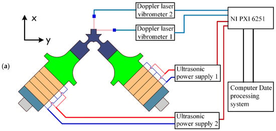
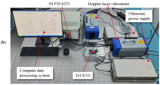
Figure 11.
The vibration trajectory testing system: (a) the schematic diagram of the elliptical trajectory testing system, (b) the experimental site.
The experimental setup is illustrated in Figure 11b. The sinusoidal voltage amplitude of both sets of ultrasonic drivers is 220 V, with a frequency of 36.5 kHz. In this study, four sets of vibration trajectory tests were conducted under phase differences of 45°, 90°, 135°, and 180°, respectively. After processing the experimental data using MATLAB, the results shown in Figure 12 were obtained. It can be observed that as the phase difference increases, the major axis of the ellipse decreases, and the minor axis reaches its maximum at a phase difference of 90°. With further increase in the phase difference, the minor axis decreases, and the elliptical shape gradually flattens, resulting in a reduction in area. At a phase difference of 180°, the elliptical shape degenerates into a straight line. The observed trend aligns with the theoretical calculations. Therefore, it can be concluded that the dual-excitation UEVC device arranged at 90° demonstrates good decoupling effects. By adjusting the phase difference of the excitation signals in the two branches, various desired elliptical trajectories can be generated at the tip of the device, facilitating the achievement of specific machining effects by controlling the shape of the elliptical trajectory and its relative angle with the workpiece surface.
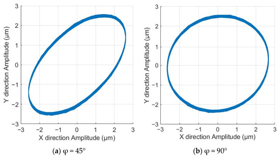
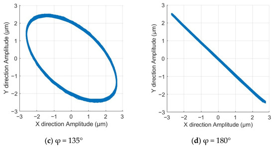
Figure 12.
End effector vibration trajectory under different phases.
Furthermore, under the condition of a 90° phase difference between the excitation signals of the two sets of ultrasonic drivers and a frequency of 36.5 kHz, elliptical trajectories were tested at different input voltages, as shown in Figure 13. It is observed that when the phase difference is maintained at a constant value, the elliptical trajectory generated at the end increases in size with the increase in voltage. Therefore, by adjusting the phase difference and excitation voltage, different elliptical trajectories can be generated at the output end, enabling precise control over the elliptical trajectory. The experimental results demonstrate that the newly developed D-UEVC device can generate accurate and adjustable elliptical trajectories. Compared to the simulation results, the experimental error is approximately 0.3–0.4 μm, and the measured vibration of the tool tip matches the simulation results, validating the rationality and feasibility of the D-UEVC device design.
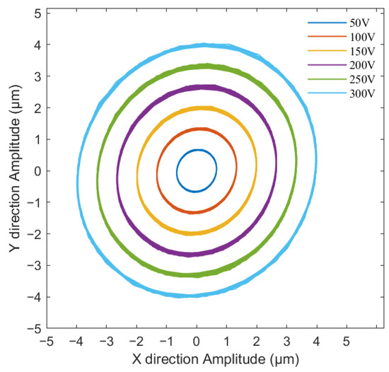
Figure 13.
Elliptical trajectories at different voltages (φ = 90°).
4.3. Cutting Experiment of Inconel 718
The cutting experiment was conducted to verify the performance of the D-UEVC in machining. As the nickel-based superalloy Inconel 718 is a difficult-to-machine material, traditional machining methods often result in severe tool wear and poor surface quality. Hence, we selected a 30 mm diameter and 50 mm length rod of Inconel 718 as the experimental material. The cutting system depicted in Figure 14 was utilized for the experiment, with the D-UEVC device mounted on the UPT-250 ultra-precision machine tool. The phase difference of the two branches of the device was fixed at 90°, and an elliptical trajectory with the Xw axis perpendicular to the cutting direction was employed for facing milling of Inconel 718. The specific experimental parameters are detailed in Table 3.
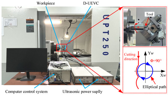
Figure 14.
The cutting experiment of D-UEVC.

Table 3.
Experimental parameters.
Figure 15a,b display magnified images of the two types of machined surface morphology captured by VHX970F at a 1000-times magnification. The conventionally cut (CC) surface exhibits irregular shapes and multiple defects. For UEVC, the two-dimensional ultrasonic vibration leads to an elliptical locus cutting of the tool tip, resulting in a relatively smooth machined surface with a regular wavy microstructure. In UEVC, a cutting period can be divided into four stages [34]: contact, cutting, separation, and contact during the vibration period. And then the tool is moved to the position where the next period of cutting starts to begin the next period of cutting. Thus, UEVC leads to less cutting time and promotes heat dissipation. The comparison clearly illustrates the significant alteration in the machined surface morphology by the ultrasonic elliptical vibration cutting. Figure 15c,d present the machined surface morphology measured using a white light interferometer. Compared to CC, UEVC results in a more uniform furrow with the summarized measurement results, as shown in Figure 16a, indicating that the average surface roughness (Ra) of the UEVC machined surface is approximately 0.215, while the CC machined surface roughness is about Ra = 0.36 μm, representing a reduction of approximately 40% in surface roughness. Additionally, experiments were conducted to assess the impact of different amplitudes (voltages) of the D-UEVC device on surface roughness. As shown in Figure 16b, the roughness of the machined surface increases as the amplitude increases.
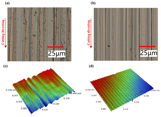
Figure 15.
Surface micro-morphology and roughness of different cutting methods: (a,c) CC surface micro-morphology; (b,d) UEVC surface micro-morphology (cutting speed = 4 m/min).
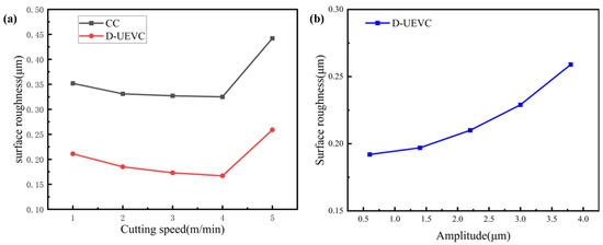
Figure 16.
The effect of the cutting parameters on surface roughness: (a) effect of cutting speed on the surface roughness, (b) effect of amplitude on the surface roughness (speed: 5 m/min).
The experimental results demonstrate that the newly developed D-UEVC device can effectively machine the difficult-to-machine material Inconel 718, producing excellent machined surfaces and exhibiting a certain ability for variable trajectory machining.
5. Conclusions
In this study, we developed an innovative double-excitation ultrasonic elliptical vibration-assisted machining device, which presents a novel approach to machining hard and brittle materials. The device underwent vibration characteristic testing and cutting experiments, leading to the following conclusions:
- A D-UEVC device with two excitation sources arranged at 90° was designed through theoretical calculations, yielding a resonant frequency of 36.5 KHz. Finite element analysis validated the device’s ability to produce an adjustable elliptical locus at the tool tip.
- An experimental verification of the vibration characteristics of the D-UEVC device was conducted, including tests on the elliptical trajectory at the tool tip under different voltages and excitation phase differences. These experiments confirmed the theoretical model and simulation analysis.
- Cutting experiments were performed on Inconel 718 rods using both conventional cutting (CC) and ultrasonic elliptical vibration cutting (UEVC) methods. The results showed that the surface roughness after CC processing was approximately Ra = 0.36 μm, while the surface roughness after UEVC processing was Ra = 0.215 μm. The utilization of the D-UEVC device led to a reduction of approximately 40% in the surface roughness of Inconel 718.
Author Contributions
Conceptualization and methodology G.H. and W.X.; Design and Performance testing of Elliptical Vibration Cutting Device W.X.; Cutting test and result analysis M.Z.; Machining programming and operation Y.L. and S.Z.; Surface morphology testing J.L. and K.Z. All authors have read and agreed to the published version of the manuscript.
Funding
The authors would like to acknowledge the financial support from the Post-doctoral Science Foundation of China 2021M692386, Tianjin Science and Technology project 22JCYBJC01630, and Tianjin Education Commission Project 2021KJ028.
Data Availability Statement
Data are contained within the article.
Conflicts of Interest
The authors declare no conflicts of interest.
References
- Shamoto, E.; Moriwaki, T. Ultaprecision diamond cutting of hardened steel by applying elliptical vibration cutting. CIRP Ann. 1999, 48, 441–444. [Google Scholar] [CrossRef]
- Su, Q.; Su, G.; Shen, X.; Wang, B.; Du, J.; Zhang, P. Design of an ultrasonic elliptical vibration cutting tool based on an eccentric cone. Int. J. Adv. Manuf. Technol. 2023, 124, 1003–1016. [Google Scholar] [CrossRef]
- Ding, H.; Chen, S.-J.; Ibrahim, R.; Cheng, K. Investigation of the size effect on burr formation in two-dimensional vibration-assisted micro end milling. Proc. Inst. Mech. Eng. Part B J. Eng. Manuf. 2011, 225, 2032–2039. [Google Scholar] [CrossRef]
- Ding, K.; Li, Q.; Lei, W.; Zhang, C.; Xu, M.; Wang, X. Design of a defined grain distribution brazed diamond grinding wheel for ultrasonic assisted grinding and experimental verification. Ultrasonics 2022, 118, 106577. [Google Scholar] [CrossRef]
- Bin, F.; Zhonghang, Y.; Depeng, L.; Liying, G. Effect of ultrasonic vibration on finished quality in ultrasonic vibration assisted micromilling of Inconel718. Chin. J. Aeronaut. 2021, 34, 209–219. [Google Scholar]
- Ma, C.X.; Shamoto, E.; Moriwaki, T. Study on the thrust cutting force in ultrasonic elliptical vibration cutting. In Materials Science Forum; Trans Tech Publications Ltd.: Bäch, Switzerland, 2004; Volume 471, pp. 396–400. [Google Scholar]
- Li, Y.; Yang, Y.; Wang, Y.; Gao, F. Study on the Simulation and Experiment of Ultrasonic-assisted Vibration Drilling of, Ti6Al4V. J. Phys. Conf. Ser. 2020, 2242, 012011. [Google Scholar] [CrossRef]
- Chen, J.; Xu, M.; Xie, C.; Du, J.; Dai, H.; Fang, Q. A nonuniform moving heat source model for temperature simulation in ultrasonic-assisted cutting of titanium alloys. Int. J. Adv. Manuf. Technol. 2018, 97, 3009–3021. [Google Scholar] [CrossRef]
- Celaya, A.; Lopez de Lacalle, L.N.; Campa, F.J.; Lamikiz, A. Ultrasonic assisted turning of mild steels. Int. J. Mater. Prod. Technol. 2010, 37, 60–70. [Google Scholar] [CrossRef]
- Brehl, D.E.; Dow, T.A. Review of vibration-assisted machining. Precis. Eng. 2008, 32, 153–172. [Google Scholar] [CrossRef]
- Yang, Z.; Zhu, L.; Zhang, G.; Ni, C.; Lin, B. Review of ultrasonic vibration-assisted machining in advanced materials. Int. J. Mach. Tools Manuf. 2020, 156, 103594. [Google Scholar] [CrossRef]
- Feng, Y.; Hsu, F.C.; Lu, Y.T.; Lin, Y.F.; Lin, C.T.; Lin, C.F.; Liang, S.Y. Surface roughness prediction in ultrasonic vibration-assisted milling. J. Adv. Mech. Des. Syst. Manuf. 2020, 14, JAMDSM0063. [Google Scholar] [CrossRef]
- Jiang, T.; Yang, J.; Pi, J.; Luo, W.; Zhang, J. Experimental and analytical study of ultrasonic elliptical vibration cutting of micro-pyramid reflective mold based on guided wave transmission. Int. J. Adv. Manuf. Technol. 2022, 118, 237–253. [Google Scholar] [CrossRef]
- Suárez, A.; Veiga, F.; de Lacalle, L.N.L.; Polvorosa, R.; Lutze, S.; Wretland, A. Effects of ultrasonics-assisted face milling on surface integrity and fatigue life of Ni-Alloy 718. J. Mater. Eng. Perform. 2016, 25, 5076–5086. [Google Scholar] [CrossRef]
- Guofu, G.; Ziwen, X.; Zhaojie, Y.; Xiang, D.; Bo, Z. Influence of longitudinal-torsional ultrasonic-assisted vibration on micro-hole drilling, Ti-6Al-4V. Chin. J. Aeronaut. 2021, 34, 247–260. [Google Scholar]
- Zhang, J.; Zhang, J.; Rosenkranz, A.; Suzuki, N.; Shamoto, E. Frictional properties of surface textures fabricated on hardened steel by elliptical vibration diamond cutting. Precis. Eng. 2019, 59, 66–72. [Google Scholar] [CrossRef]
- Zhao, B.; Chang, B.; Wang, X.; Bie, W. System design and experimental research on ultrasonic assisted elliptical vibration grinding of Nano-ZrO2 ceramics. Ceram. Int. 2019, 45, 24865–24877. [Google Scholar] [CrossRef]
- Li, L.; Xu, J.; Ji, M.; Yin, Y.; Chen, M. On crack suppression mechanisms of ultrasonic elliptical vibration cutting of 3Y-TZP ceramics. Ceram. Int. 2022, 48, 28308–28326. [Google Scholar] [CrossRef]
- Han, L.; Zhang, J.; Chen, J.; Zhang, J.; Liu, H.; Yan, Y.; Sun, T. Influence of vibration parameters on ultrasonic elliptical vibration cutting of reaction-bonded silicon carbide. Int. J. Adv. Manuf. Technol. 2020, 108, 427–437. [Google Scholar] [CrossRef]
- Zhou, J.; Lu, M.; Lin, J.; Du, Y. Elliptic vibration assisted cutting of metal matrix composite reinforced by silicon carbide: An investigation of machining mechanisms and surface integrity. J. Mater. Res. Technol. 2021, 15, 1115–1129. [Google Scholar] [CrossRef]
- Zhang, J.; Suzuki, N.; Wang, Y.; Shamoto, E. Fundamental investigation of ultra-precision ductile machining of tungsten carbide by applying elliptical vibration cutting with single crystal diamond. J. Mater. Process. Technol. 2014, 214, 2644–2659. [Google Scholar] [CrossRef]
- Nath, C.; Rahman, M.; Neo, K.S. A study on ultrasonic elliptical vibration cutting of tungsten carbide. J. Mater. Process. Technol. 2009, 209, 4459–4464. [Google Scholar] [CrossRef]
- Yin, Z.; Fu, Y.; Xu, J.; Li, H.; Cao, Z.; Chen, Y. A novel single driven ultrasonic elliptical vibration cutting device. Int. J. Adv. Manuf. Technol. 2017, 90, 3289–3300. [Google Scholar] [CrossRef]
- Guo, P.; Ehmann, K.F. Development of a tertiary motion generator for elliptical vibration texturing. Precis. Eng. 2013, 37, 364–371. [Google Scholar] [CrossRef]
- Kurniawan, R.; Ko, T.J.; Ping, L.C.; Kumaran, S.T.; Kiswanto, G.; Guo, P.; Ehmann, K.F. Development of a two-frequency, elliptical-vibration texturing device for surface texturing. J. Mech. Sci. Technol. 2017, 31, 3465–3473. [Google Scholar] [CrossRef]
- Yang, Y.; Gao, S.; Chen, K.; Pan, Y.; Guo, P. Vibration analysis and development of an ultrasonic elliptical vibration tool based on a portal frame structure. Precis. Eng. 2017, 50, 421–432. [Google Scholar] [CrossRef]
- Huang, Z.P.; Pi, J.; Yang, G. Realization of two dimensional high frequency ultrasonic vibration using guided wave transmission. Mech. Sci. Technol. Aerosp. Eng. 2019, 38, 230–236. [Google Scholar]
- Jiang, Y.; Pi, J.; Zhang, Y.; Jiang, T.; Yang, G.; Shen, Z. Research on the tool tip trajectory deflection control and cutting characteristics of elliptical vibration cutting based on guided wave transmission. Int. J. Adv. Manuf. Technol. 2020, 108, 3101–3117. [Google Scholar] [CrossRef]
- Sen, Y.; Yan, B.; Yanan, P.; Zhigang, D.; Zhuji, J.; Renke, K. Development of ultrasonic elliptical vibration cutting device with multi-stage amplification function. J. Mech. Eng. 2022, 58, 260–268. [Google Scholar]
- Yang, J.; Feng, P.; Zhang, J.; Wang, J. Design optimization of ultrasonic vibration cutting tool to generate well-decoupled elliptical trajectory. Int. J. Adv. Manuf. Technol. 2022, 119, 7199–7214. [Google Scholar] [CrossRef]
- Moriwaki, T.; Shamoto, E. Ultrasonic elliptical vibration cutting. CIRP Ann. 1995, 44, 31–34. [Google Scholar] [CrossRef]
- Richardson, A.; Walsh, K.K.; Abdullah, M.M. Closed-form equations for coupling linear structures using stiffness and damping elements. Struct. Control Health Monit. 2013, 20, 259–281. [Google Scholar] [CrossRef]
- Kurniawan, R.; Ali, S.; Park, K.M.; Li, C.P.; Ko, T.J. Development of a three-dimensional ultrasonic elliptical vibration transducer (3D-UEVT) based on sandwiched piezoelectric actuator for micro-grooving. Int. J. Precis. Eng. Manuf. 2019, 20, 1229–1240. [Google Scholar] [CrossRef]
- Zhou, M.; Hu, L. Development of an innovative device for ultrasonic elliptical vibration cutting. Ultrasonics 2015, 60, 76–81. [Google Scholar] [CrossRef] [PubMed]
Disclaimer/Publisher’s Note: The statements, opinions and data contained in all publications are solely those of the individual author(s) and contributor(s) and not of MDPI and/or the editor(s). MDPI and/or the editor(s) disclaim responsibility for any injury to people or property resulting from any ideas, methods, instructions or products referred to in the content. |
© 2024 by the authors. Licensee MDPI, Basel, Switzerland. This article is an open access article distributed under the terms and conditions of the Creative Commons Attribution (CC BY) license (https://creativecommons.org/licenses/by/4.0/).