

Flexible Continuum Robot System for Minimally Invasive Endoluminal Gastrointestinal Endoscopy


Abstract
1. Introduction
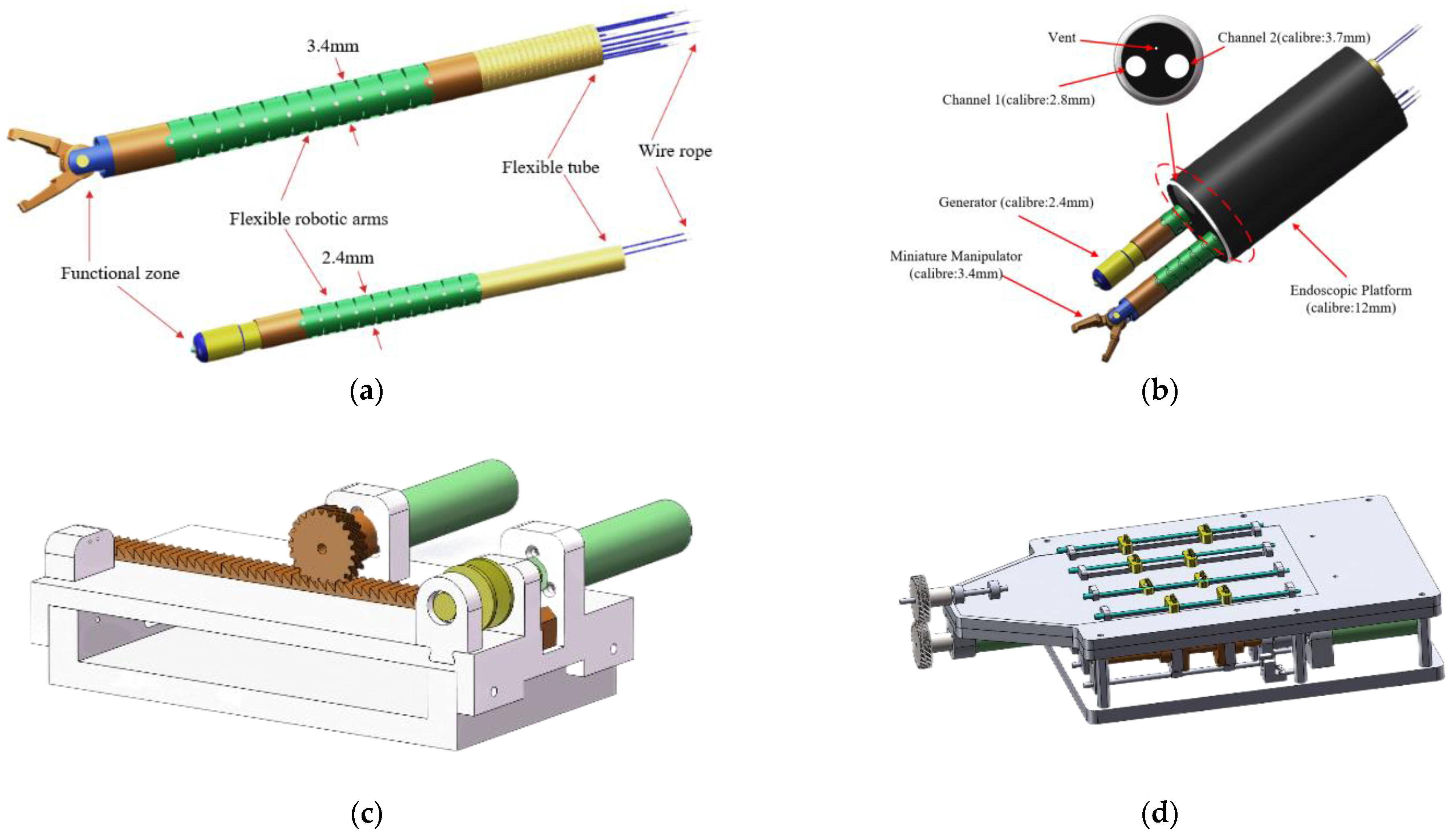
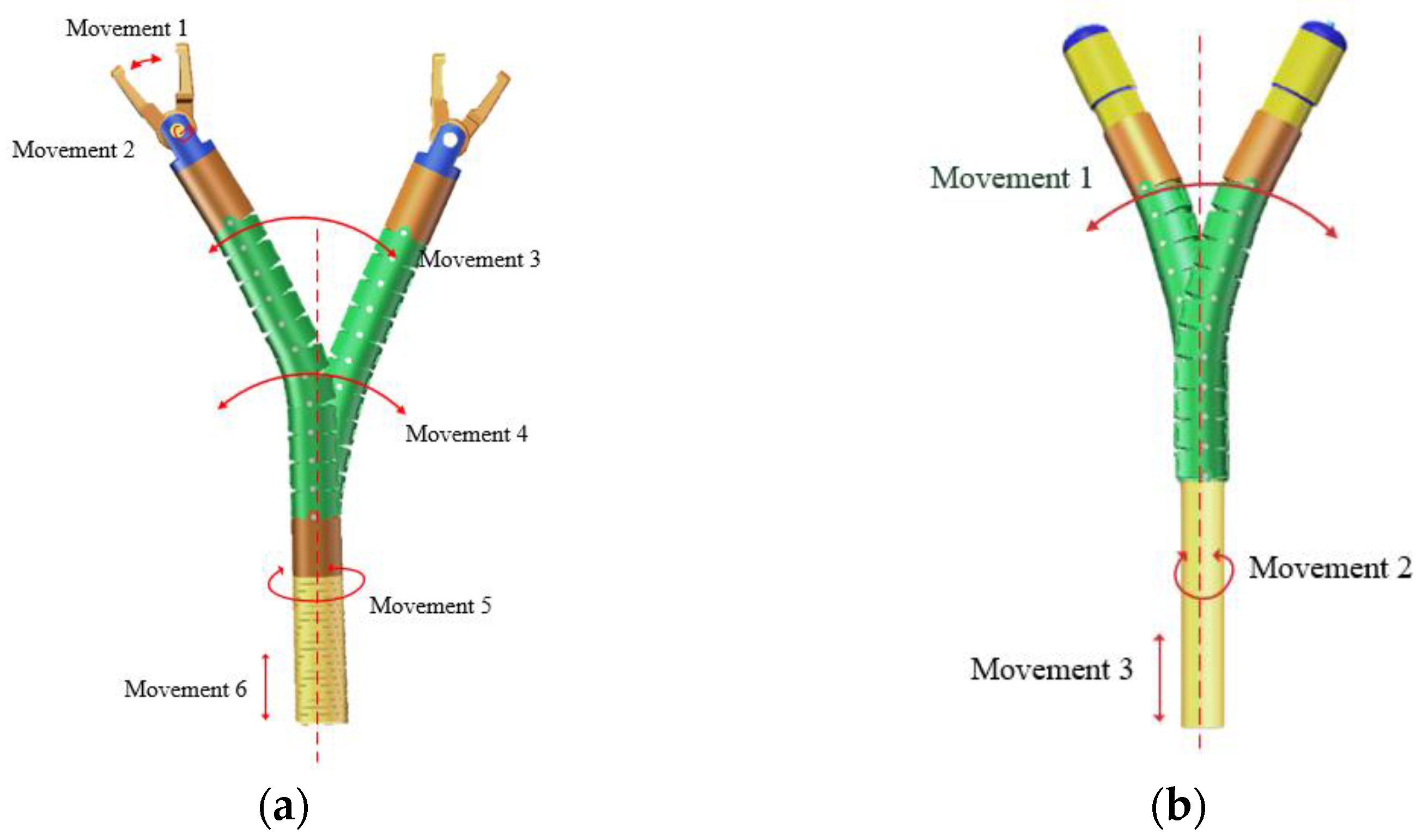
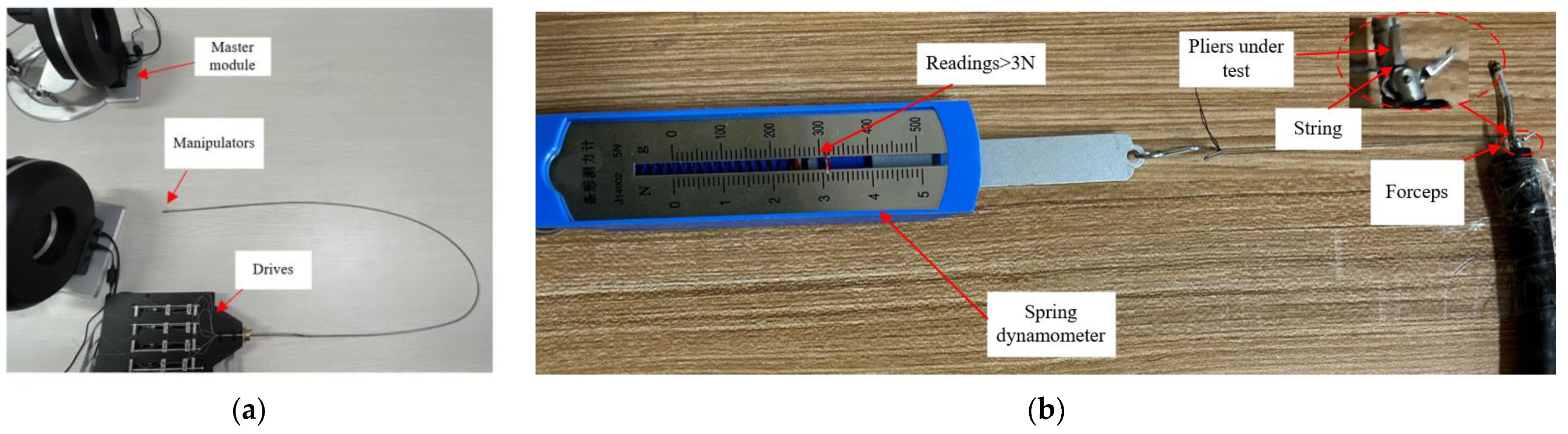
- We have developed a minimally invasive surgical robot system with a compact mechanical structure. The diameter of the manipulator is only 3.4 mm, and the electrosurgical knife diameter is 2.4 mm. Utilizing a flexible mechanical arm, this robot exhibits outstanding flexibility with 9 degrees of freedom, while also possessing a sufficient gripping force (>3 N).
- The driving system employs a design where two ropes are simultaneously driven by bidirectional ball screws. This design converts the motion of opening and closing the forceps at the instrument’s head into a linear motion, aiming to facilitate more precise control of displacement during closed-loop positioning control and improve system accuracy.
- We conducted a theoretical analysis of the robot, along with testing the robot’s gripping force and flexibility. Finally, we performed in vivo experiments to validate the robot’s performance in basic operations.
2. Materials and Methods
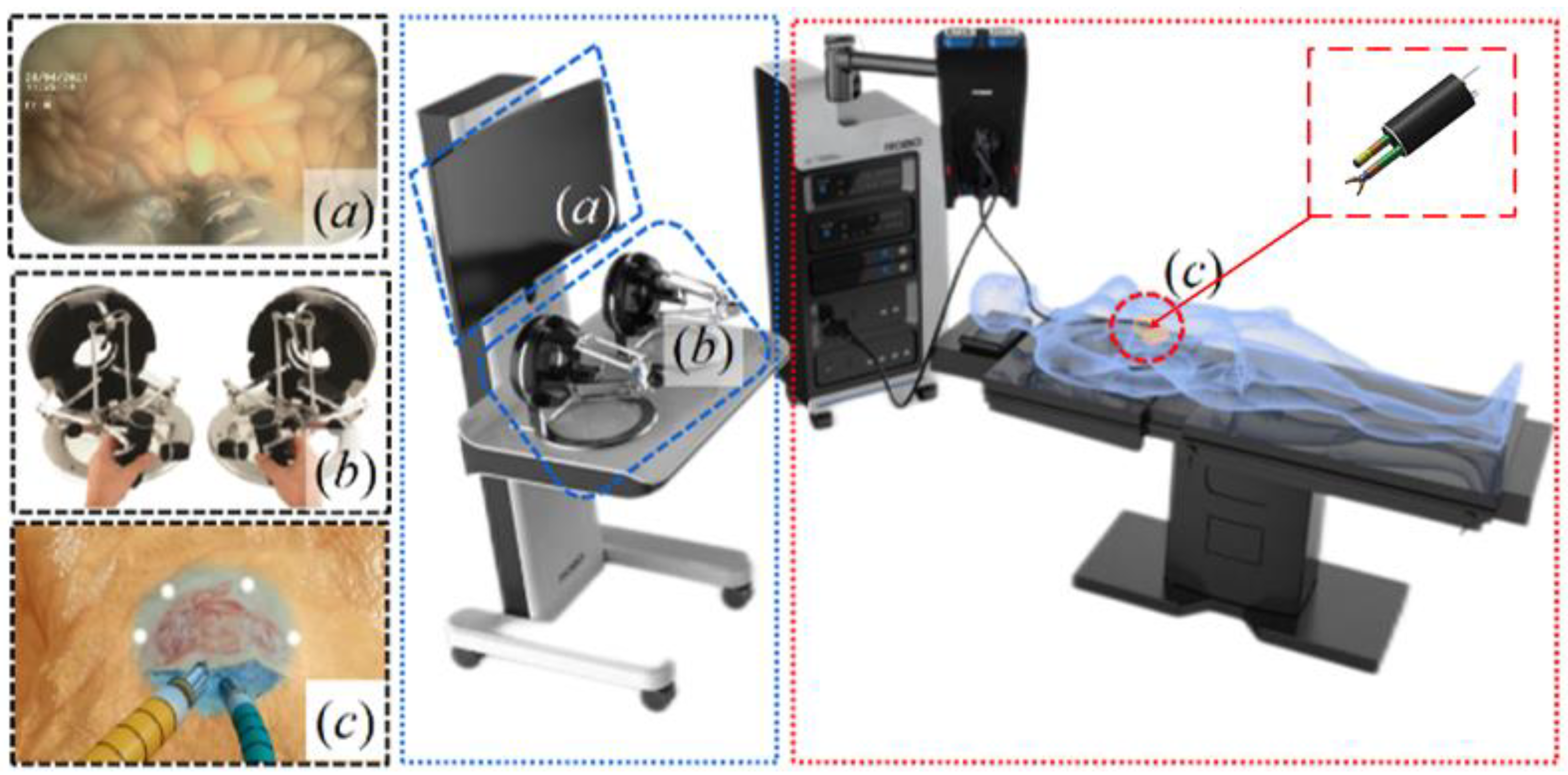
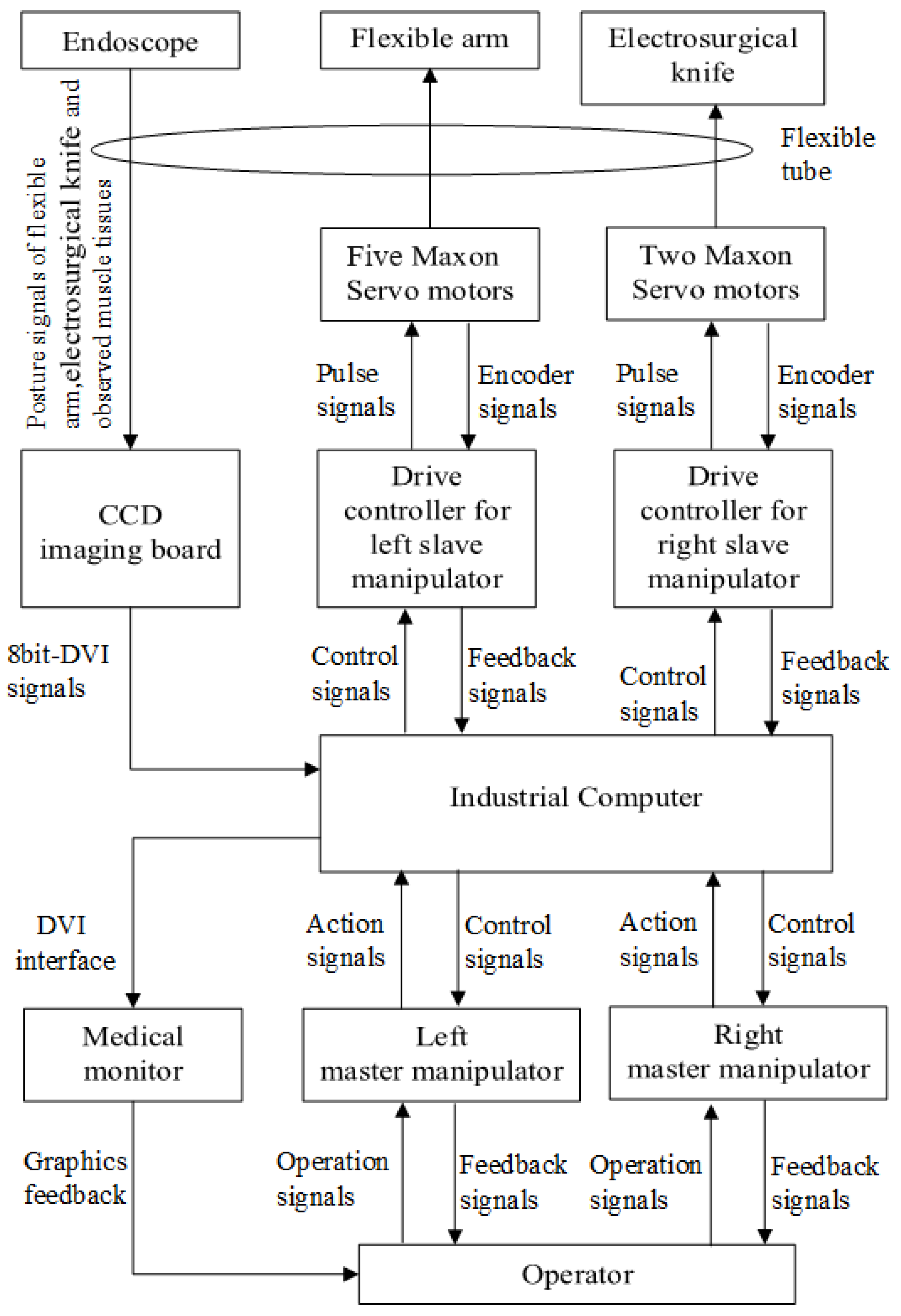
2.1. System Overview
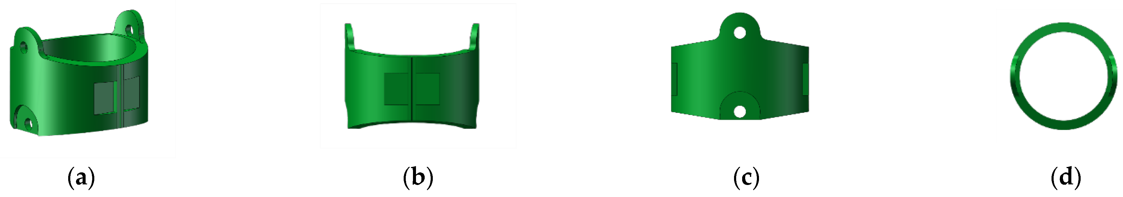
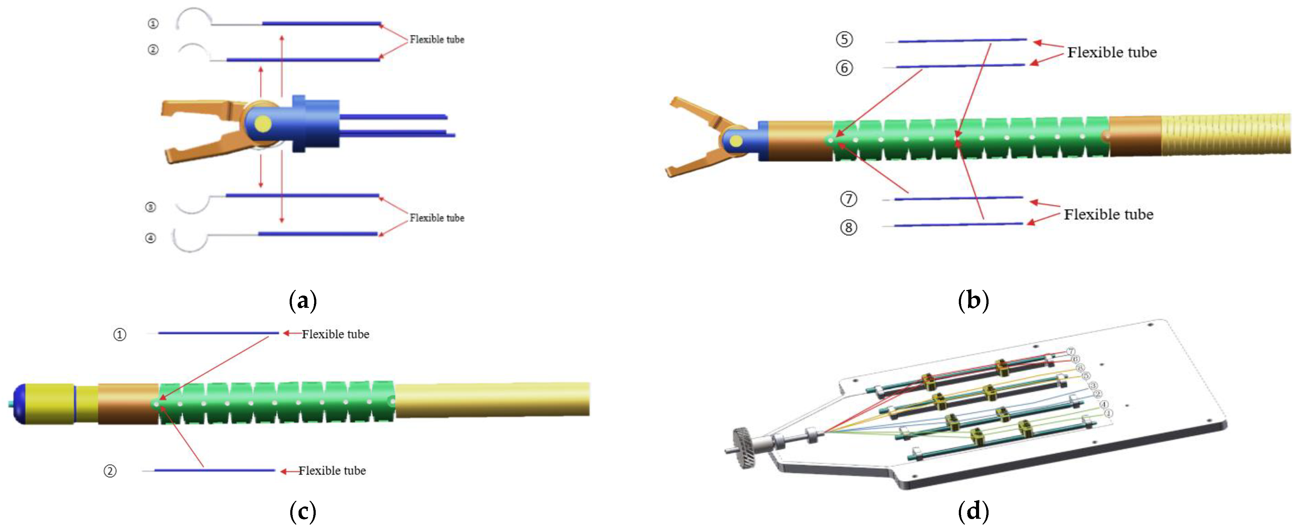
2.2. Manipulators
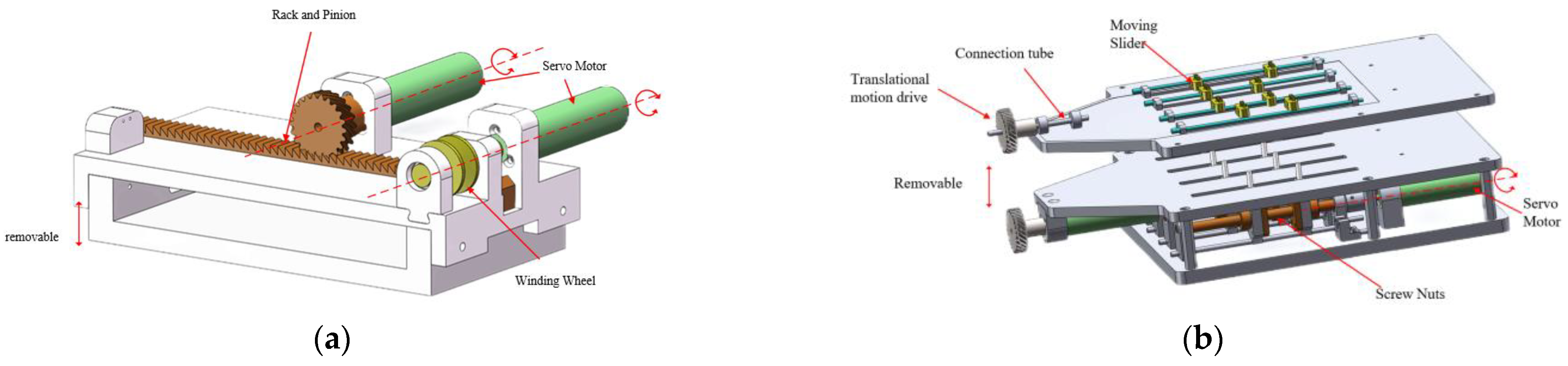
2.3. Drive Systems
2.4. Drive Systems
3. Theoretical Analysis
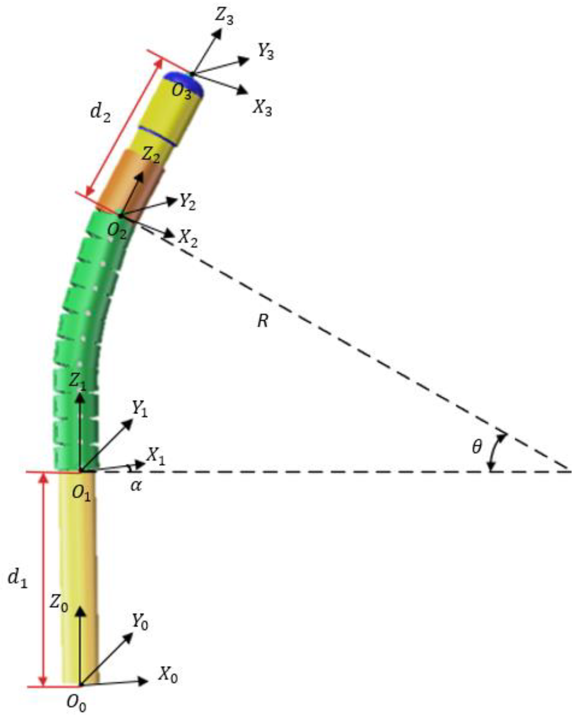
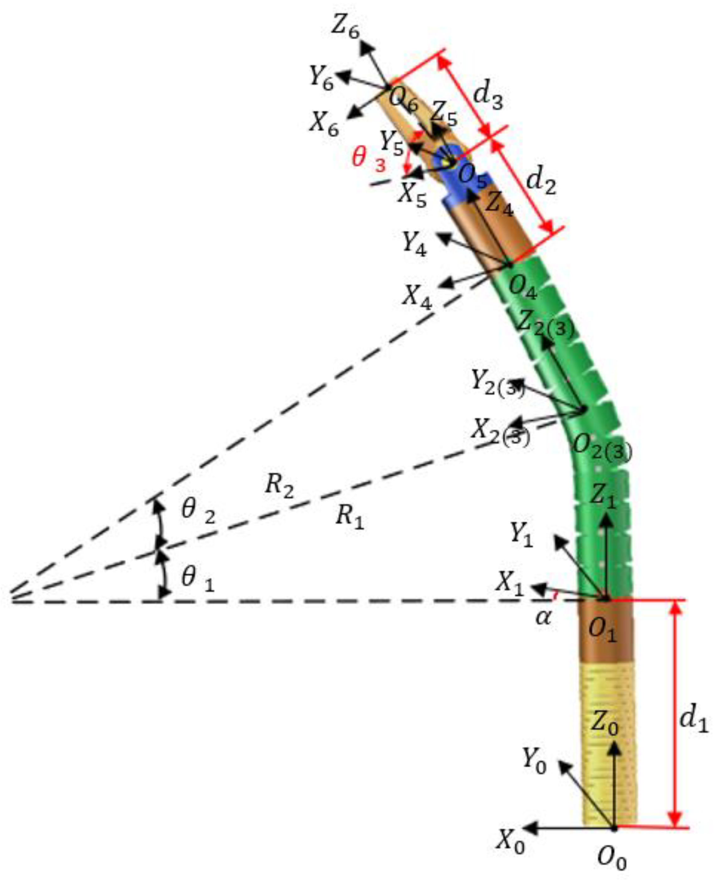
3.1. Kinematics
3.1.1. Electric Scalpel Kinematic Model
3.1.2. Kinematic Model of the Robotic Arm
3.2. Establishment of Dynamic Models
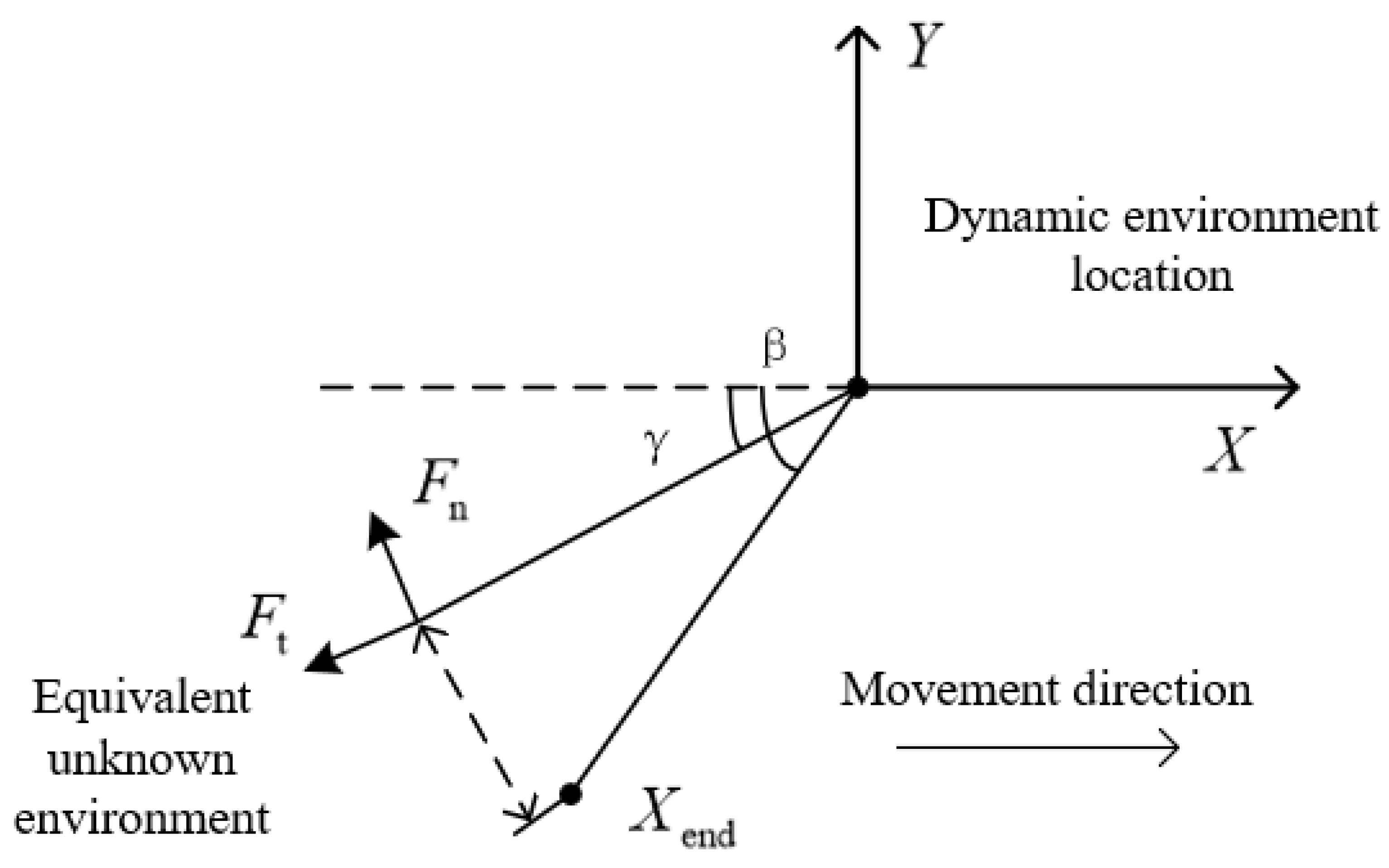
3.2.1. Analysis of Dynamic Interaction Environment Model
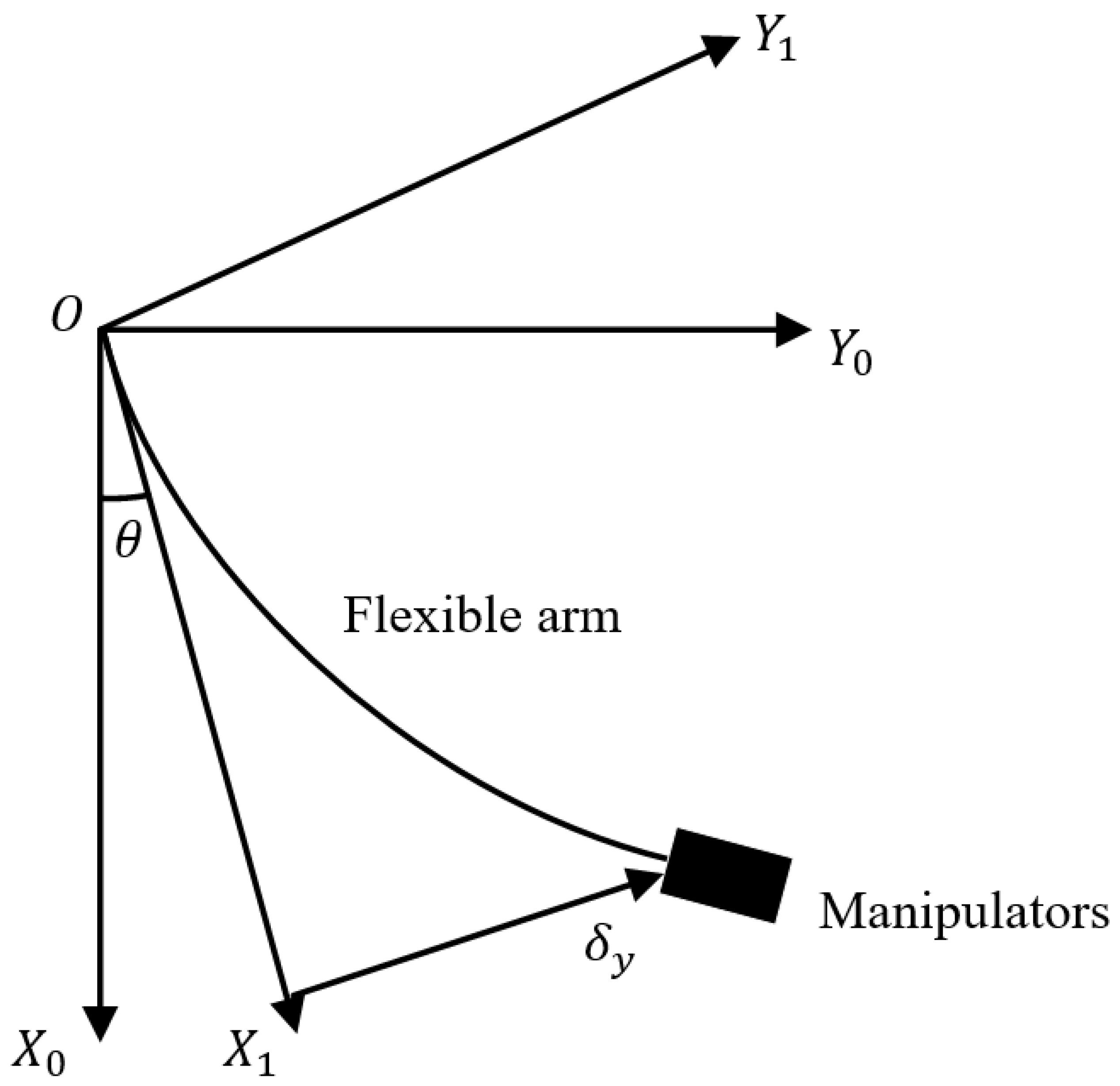
3.2.2. Kinematic Analysis of the Robotic Arm
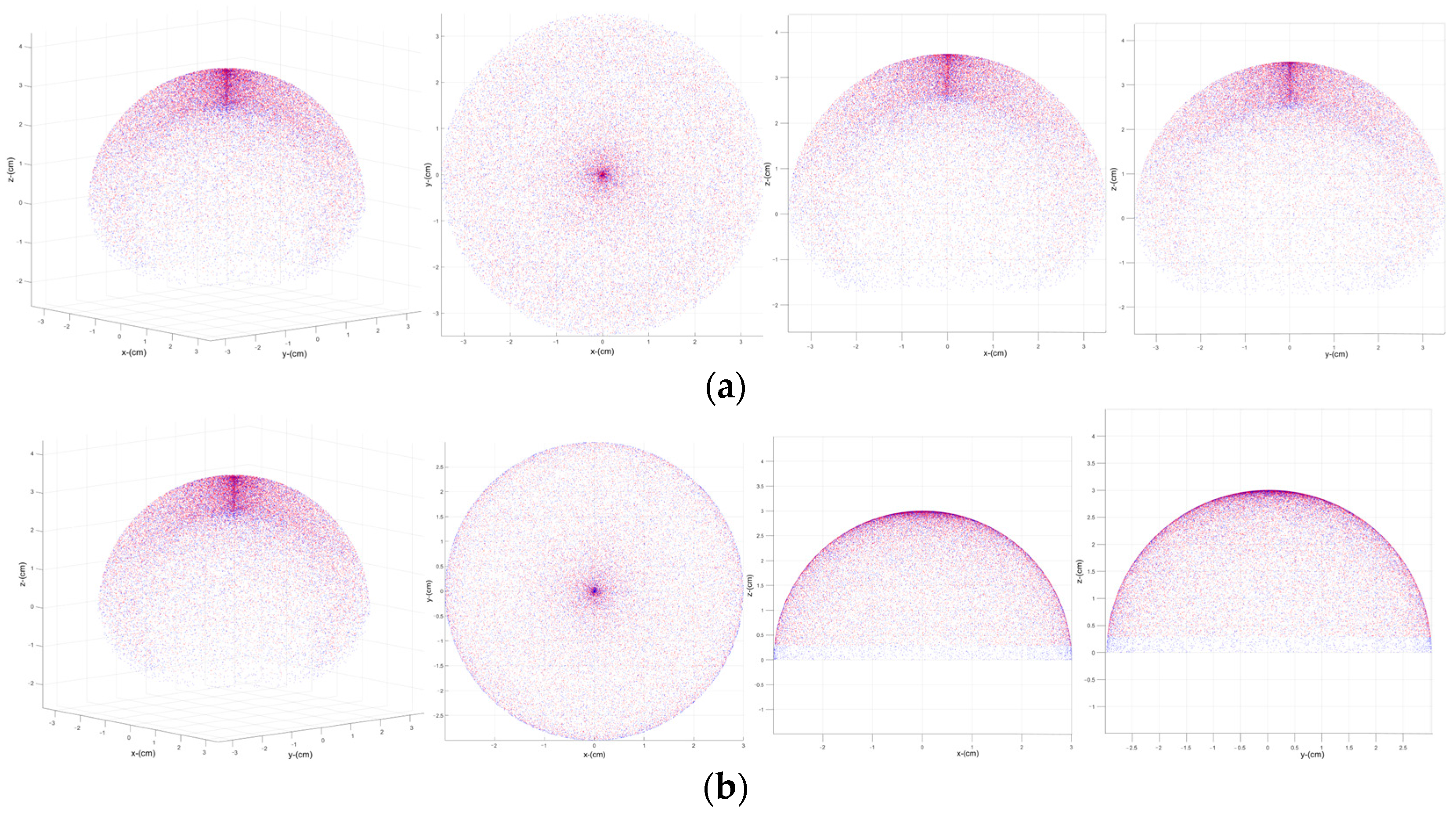
3.3. Workspace
4. Experimental Testing
4.1. Grasping Force Test
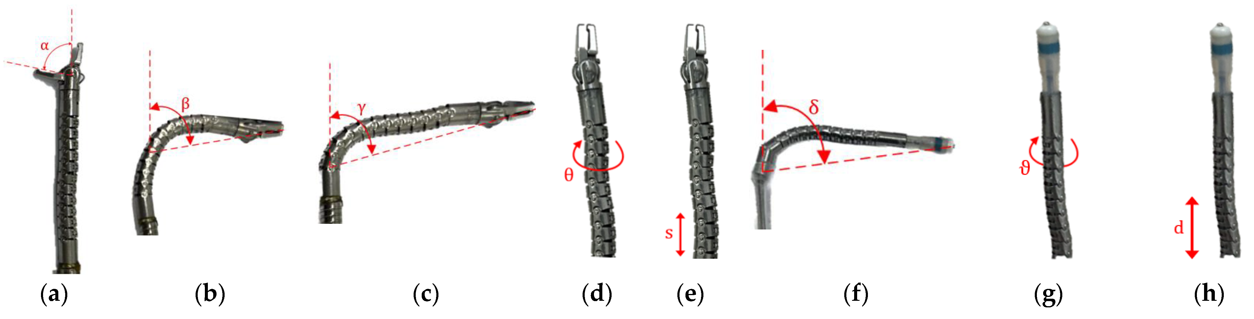
4.2. Performance Testing
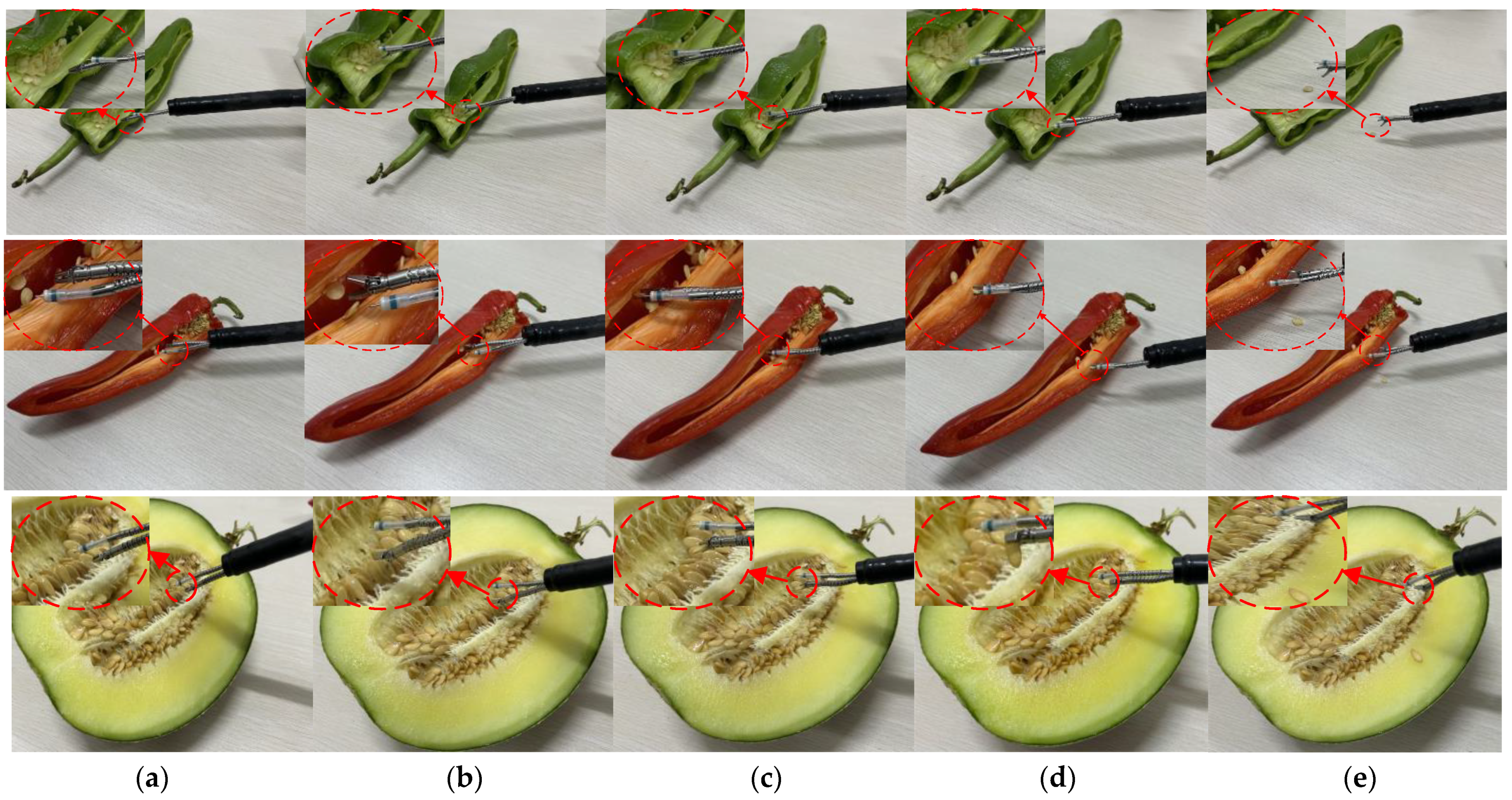
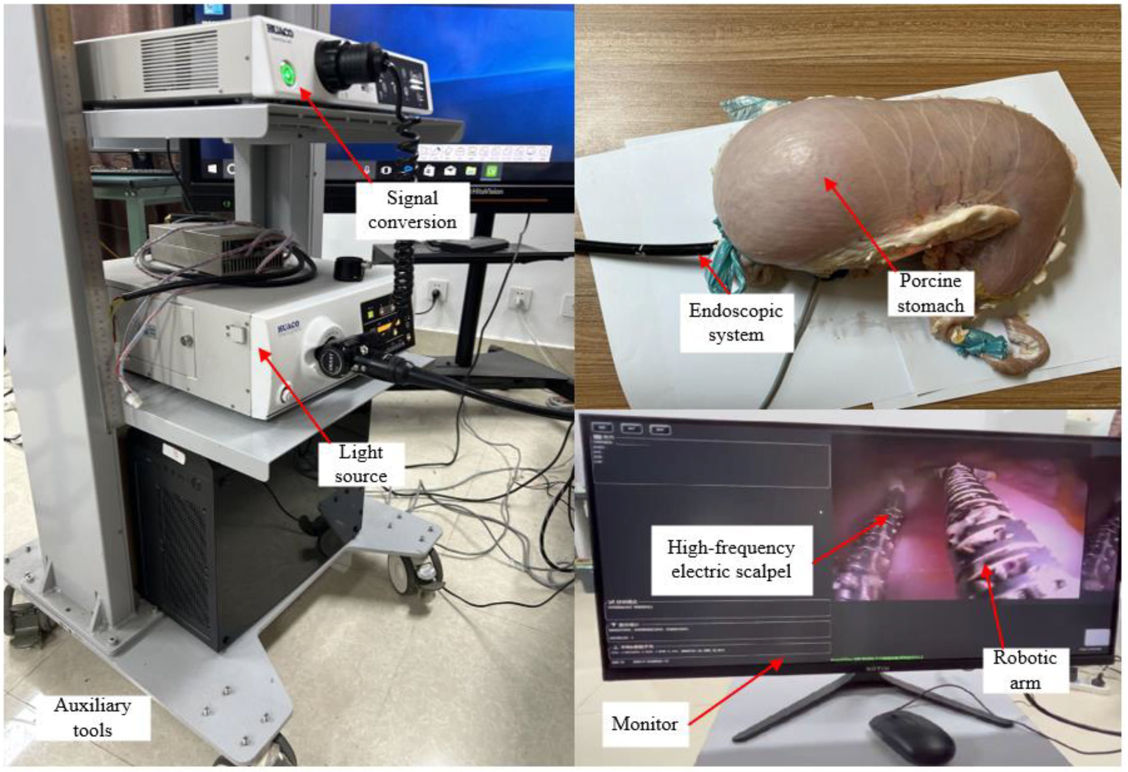
4.3. In Vitro Experiments
5. Conclusions and Future Work
Author Contributions
Funding
Data Availability Statement
Conflicts of Interest
References
- Ferlay, J.; Colombet, M.; Soerjomataram, I.; Parkin, D.M.; Piñeros, M.; Znaor, A.; Bray, F. Cancer statistics for the year 2020: An overview. Int. J. Cancer 2021, 149, 778–789. [Google Scholar] [CrossRef] [PubMed]
- Omisore, O.M.; Han, S.; Xiong, J. A Review on Flexible Robotic Systems for Minimally Invasive Surgery along with some of the technical and technological challenges hindering their prominence. IEEE Trans. Syst. Man Cybern. Syst. 2020, 52, 631–644. [Google Scholar] [CrossRef]
- Burgner-Kahrs, J.; Rucker, D.C.; Choset, H. Continuum robots for medical applications: A survey. IEEE Trans. Robot. 2015, 31, 1261–1280. [Google Scholar] [CrossRef]
- Yung, K.; Cheung, J.; Chung, S.; Singh, S.; Yeung, C. A single-port robotic platform for laparoscopic surgery with a large central channel for additional instrument. Ann. Biomed. Eng. 2017, 45, 2211–2221. [Google Scholar] [CrossRef] [PubMed]
- Piccigallo, M.; Scarfogliero, U.; Quaglia, C.; Petroni, G.; Valdastri, P. Design of a novel bimanual robotic system for single-port laparoscopy. IEEE/ASME Trans. Mechatron. 2010, 15, 871–878. [Google Scholar] [CrossRef]
- Kim, C.G. Natural orifice transluminal endoscopic surgery and upper gastrointestinal tract. J. Gastric Cancer 2013, 13, 199–206. [Google Scholar] [CrossRef] [PubMed]
- Li, Y.; Richter, F.; Lu, J.; Funk, E.K.; Orosco, R.K.; Zhu, J.; Yip, M.C. Super: A surgical perception framework for endoscopic tissue manipulation with surgical robotics. IEEE Robot. Autom. Lett. 2020, 5, 2294–2301. [Google Scholar] [CrossRef]
- Choi, H.; Kwak, H.; Lim, Y.; Kim, H. Surgical robot for single-incision laparoscopic surgery. IEEE Trans. Bio-Med. Eng. 2014, 61, 2458. [Google Scholar] [CrossRef] [PubMed]
- Poon, H.; Li, C.; Gao, W.; Ren, H.; Lim, C.M. Evolution of robotic systems for transoral head and neck surgery. Oral Oncol. 2018, 87, 82–88. [Google Scholar] [CrossRef]
- Zhao, J.; Feng, B.; Zheng, M.H.; Xu, K. Surgical robots for SPL and NOTES: A review. Minim. Invasive Ther. 2015, 24, 8–17. [Google Scholar] [CrossRef]
- Quaglia, C.; Petroni, G.; Niccolini, M.; Caccavaro, S.; Dario, P. Design of a compact robotic manipulator for single-port laparoscopy. J. Mech. Des. 2014, 136, 105001. [Google Scholar] [CrossRef]
- Ren, H. Computer-assisted transoral surgery with flexible robotics and navigation technologies: A review of recent progress and research challenges. Crit. Rev. Biomed. Eng. 2013, 41, 4–5. [Google Scholar] [CrossRef] [PubMed]
- Zhan, Y.; Duan, X.G.; Cui, T.F.; Han, D.Q. Craniotomy robot system based on human-machine parallel collaboration. In Proceedings of the 2016 IEEE International Conference on Mechatronics and Automation, Heilongjiang, China, 7–10 August 2016; pp. 1119–1124. [Google Scholar]
- Li, C.; Gu, X.; Xiao, X.; Lim, C.M.; Ren, H. A robotic system with multichannel flexible parallel manipulators for single port access surgery. IEEE Trans. Ind. Inform. 2019, 15, 1678–1687. [Google Scholar] [CrossRef]
- Hu, Y.; Zhang, L.; Li, W.; Yang, G.-Z. Design and fabrication of a 3-d printed metallic flexible joint for snake-like surgical robot. IEEE Robot. Autom. Lett. 2019, 4, 1557–1563. [Google Scholar] [CrossRef]
- Sun, Y.; Song, S.; Liang, X.; Ren, H. A miniature soft robotic manipulator based on novel fabrication methods. IEEE Robot. Autom. Lett. 2016, 1, 617–623. [Google Scholar] [CrossRef]
- Jin, X.; Feng, M.; Zhao, J.; Li, J. Design a flexible surgical instrument for robot-assisted minimally invasive surgery. In Proceedings of the 2016 IEEE International Conference on Robotics and Biomimetics (ROBIO), Qingdao, China, 3–7 December 2016; pp. 260–264. [Google Scholar]
- Harvey, L.; Hendrick, R.; Dillon, N.; Blum, E.; Branscombe, L.; Webster, S.; Webster, R.J.; Anderson, T. A novel robotic endoscopic device used for operative hysteroscopy. J. Minim. Invasive Gynecol. 2020, 27, 1631–1635. [Google Scholar] [CrossRef] [PubMed]
- Gao, H.; Zhang, Z.; Li, C.; Xiao, X.; Qiu, L.; Yang, X.; Hao, R.; Zuo, X.; Li, Y.; Ren, H. GESRsim: Gastrointestinal Endoscopic Surgical Robot Simulator. In Proceedings of the 2022 IEEE/RSJ International Conference on Intelligent Robots and Systems (IROS), Kyoto, Japan, 23–27 October 2022; pp. 9542–9549. [Google Scholar]
- Ruszkowski, A.; Schneider, C.; Mohareri, O.; Salcudean, S. Bimanual teleoperation with heart motion compensation on the da Vinci Research Kit: Implementation and preliminary experiments. In Proceedings of the 2016 IEEE International Conference on Robotics and Automation (ICRA), Stockholm, Sweden, 16–21 May 2016; pp. 4101–4108. [Google Scholar]
- Prasad, S.K.; Kitakawa, M.; Fischer, G.S. A modular 2-DOF force-sensing instrument for laparoscopic surgery. In Proceedings of the International Conference on Medical Image Computing and Computer Assisted Intervention, Montreal, QC, Canada, 15–18 November 2003; pp. 279–286. [Google Scholar]
- Tavakoli, M.; Patel, R.V.; Moallern, M. Haptic interaction in robot-assisted endoscopic surgery: A sensorized end-effector. Int. J. Med. Robot. Comput. Assist. Surg. 2005, 1, 53–63. [Google Scholar] [CrossRef] [PubMed]
- Thielmann, S.; Seibold, U.; Haslinger, R.; Passing, G. MICA-a new generation of versatile instruments in robotic surgery. In Proceedings of the 2010 IEEE/RSJ International Conference on Intelligent Robots and Systems, Taipei, Taiwan, 18–22 October 2010; pp. 871–878. [Google Scholar]
- Lau, K.; Leung, E.; Chiu, W.; Yam, Y.; Lau, J.; Poon, C. A flexible surgical robotic system for removal of early-stage gastrointestinal cancers by endoscopic submucosal dissection. IEEE Trans. Ind. Inform. 2016, 12, 2365–2374. [Google Scholar] [CrossRef]
- Feng, M.; Fu, Y.; Pan, B.; Liu, C. Development of a medical robot system for minimally invasive surgery. Int. J. Med. Robot. Comput. Assist. Surg. 2012, 8, 85–96. [Google Scholar] [CrossRef]
- Tay, G.; Tan, H.; Nguyen, T.K.; Phee, S.J.; Iyer, N.G. Use of the EndoMaster robot-assisted surgical system in transoral robotic surgery: A cadaveric study. Int. J. Med. Robot. Comput. Assist. Surg. 2018, 14, e1930. [Google Scholar] [CrossRef]
- Zorn, L.; Nageotte, F.; Zanne, P.; Legner, A.; Dallemagne, B. A Novel Telemanipulated Robotic Assistant for Surgical Endoscopy: Preclinical Application to ESD. IEEE Trans. Biomed. Eng. 2018, 65, 797–808. [Google Scholar] [CrossRef] [PubMed]
- Li, C.; Gu, X.; Xiao, X.; Lim, C.M.; Ren, H. Flexible robot with variable stiffness in transoral surgery. IEEE/ASME Trans. Mechatron. 2020, 25, 1–10. [Google Scholar] [CrossRef]
- de Moura, D.T.H.; Aihara, H.; Jirapinyo, P.; Farias, G.; Hathorn, K.E.; Bazarbashi, A.; Thompson, C.C. Robot-assisted endoscopic submucosal dissection versus conventional ESD for colorectal lesions: Outcomes of a randomized pilot study in endoscopists without prior ESD experience (with video). Gastrointest. Endosc. 2019, 90, 290–298. [Google Scholar] [CrossRef]
- Chiu, P.; Ho, K.Y.; Jay, S. Colonic endoscopic submucosal dissection using a novel robotic system (with video). Gastrointest. Endosc. 2020, 93, 1172–1177. [Google Scholar] [CrossRef] [PubMed]
- Wu, L.; Song, S.; Wu, K. Development of a compact continuum tubular robotic system for nasopharyngeal biopsy. Med. Biol. Eng. Comput. 2017, 55, 403–417. [Google Scholar] [CrossRef] [PubMed]
- Hong, W.Z.; Xie, L.; Liu, J.; Sun, Y.; Li, K.; Wang, H. Development of a Novel Continuum Robotic System for Maxillary Sinus Surgery. IEEE/ASME Trans. Mechatron. 2018, 23, 1226–1237. [Google Scholar] [CrossRef]
- Morimoto, T.K.; Hawkes, E.W.; Okamura, A.M. Design of a Compact Actuation and Control System for Flexible Medical Robots. IEEE Robot. Autom. Lett. 2017, 2, 1579–1585. [Google Scholar] [CrossRef] [PubMed]
- Meng, Q.; Liu, G.; Xu, X.; Meng, Q.; Qin, L.; Yu, H. Design and Analysis of a Supine Ankle Rehabilitation Robot for Early Stroke Recovery. Machines 2023, 11, 787. [Google Scholar] [CrossRef]
- Barrientos-Diez, J.; Dong, X.; Axinte, D.; Kell, J. Real-Time Kinematics of Continuum Robots: Modeling and Validation. Robot. Comput.-Integr. Manuf. 2021, 67, 102019. [Google Scholar] [CrossRef]
- Tan, C.; Xu, P.; Li, P.; Yu, H. Current Research on Modeling and Control Methods for Cable-driven Flexible Manipulator. Inf. Control 2023, 52, 277–291. [Google Scholar]
- Dwivedy, S.K.; Eberhard, P. Dynamic Analysis of Flexible Manipulators: A Literature Review. Mech. Mach. Theory 2006, 41, 749–777. [Google Scholar] [CrossRef]
- Chen, W.; You, X.; Cui, X.; Yu, S. Dynamics Modeling and Tension Analysis for a Cable-Driven Humanoid-Arm Robot. J. Beijing Univ. Aeronaut. Astronaut. 2013, 39, 335–339. [Google Scholar]
- Yang, Z. Mechanical Vibration and Noise; Higher Education Press: Beijing, China, 2011. [Google Scholar]
- Guo, Z.; Jin, G.; Chang, B.; Wang, Y. Research of Dynamic Modeling and Performance for Rigid-Flexible Manipulators. J. Tianjin Polytech. Univ. 2013, 32, 70–74. [Google Scholar]
- Heidari, H.R.; Korayem, M.H.; Haghpanahi, M.; Batlle, V.F. A New Nonlinear Finite Element Model for the Dynamic Modeling of Flexible Link Manipulators Undergoing Large Deflections. In Proceedings of the 2011 IEEE International Conference on Mechatronics, Istanbul, Turkey, 13–15 April 2011; pp. 375–380. [Google Scholar]
- Meng, S.; Xiong, J.; Lv, Z. Modeling of Arm System of Folding-Boom Aerial Platform Vehicle. Noise Vib. Control 2012, 32, 63–67. [Google Scholar]
- Liu, X.; Huang, Y.; Cui, P.; Xu, Z. Modeling and Dynamic Characteristic Analysis of Flexible Robotic Arm. Noise Vib. Control 2014, 34, 7. [Google Scholar]
- Meng, Q.; Liu, G.; Meng, Q.; Xu, X.; Qin, L.; Yu, H. Bionic Design of a Novel Portable Hand-Elbow Coordinate Exoskeleton for Activities of Daily Living. Electronics 2023, 12, 3326. [Google Scholar] [CrossRef]
- Okamura, A.M. Methods for haptic feedback in teleoperated robot-assisted surgery. Ind. Robot-Int. J. 2004, 31, 499–508. [Google Scholar] [CrossRef]
- Kuo, Y.-L.; Liu, B.-H.; Wu, C.-Y. Pose Determination of a Robot Manipulator Based on Monocular Vision. IEEE Access 2016, 4, 8454–8464. [Google Scholar] [CrossRef]


| Device | Size | Flexibility (Degrees of Freedom, DOF) | Applications of Surgical Robots |
|---|---|---|---|
| Our Work | 2.4 mm, 3.4 mm | 9 | Minimally invasive endoscopic gastrointestinal surgery |
| [17] | 5~12 mm | 4 | Laparoscopic surgery |
| [18] | 3 mm | 8 | Hysteroscopic surgery |
| [19] | 3.5 mm, 2.5 mm | 8 | Endoscopic submucosal dissection |
| [20] | 5 mm | 2 | Laparoscopic surgery |
| [16] | 8 mm | 3 | Tonsillectomy |
| [14] | 4 mm | 6 | Endoscopic mucosal resection (EMR) |
| [21] | 10 mm | 5 | Robot-assisted endoscopic surgery |
| [13] | 11 mm | 5 | Appendectomy and nephrectomy |
| [32] | 4 mm | 4 | Maxillary sinus surgery |
| α/° | β/° | γ/° | θ/° | s/mm | δ/° | ϑ/° | d/mm | |
|---|---|---|---|---|---|---|---|---|
| First Test | 87 | 82 | 79 | 360 | 30 | 85 | 360 | 30 |
| Second Test | 85 | 84 | 84 | 360 | 30 | 83 | 360 | 30 |
| Third Test | 86 | 85 | 80 | 360 | 30 | 86 | 360 | 30 |
| Average | 86 | 83.6 | 81 | 360 | 30 | 84.6 | 360 | 30 |
| Surgical Object | Average Diameter (mm) | Minimum Diameter (mm) | Average Thickness (mm) | Surface | Duration (s) |
|---|---|---|---|---|---|
| Green pepper seeds | 2.7 | 2.5 | 0.7 | Rough and dry | 45 |
| Red pepper seeds | 2.9 | 2.7 | 0.6 | Rough and dry | 47 |
| Melon seeds | 5.2 | 4.7 | 1.9 | Smooth and moist | 55 |
Disclaimer/Publisher’s Note: The statements, opinions and data contained in all publications are solely those of the individual author(s) and contributor(s) and not of MDPI and/or the editor(s). MDPI and/or the editor(s) disclaim responsibility for any injury to people or property resulting from any ideas, methods, instructions or products referred to in the content. |
© 2024 by the authors. Licensee MDPI, Basel, Switzerland. This article is an open access article distributed under the terms and conditions of the Creative Commons Attribution (CC BY) license (https://creativecommons.org/licenses/by/4.0/).
Share and Cite
Sun, L.; Chen, X. Flexible Continuum Robot System for Minimally Invasive Endoluminal Gastrointestinal Endoscopy. Machines 2024, 12, 370. https://doi.org/10.3390/machines12060370
Sun L, Chen X. Flexible Continuum Robot System for Minimally Invasive Endoluminal Gastrointestinal Endoscopy. Machines. 2024; 12(6):370. https://doi.org/10.3390/machines12060370
Chicago/Turabian StyleSun, Liping, and Xiong Chen. 2024. "Flexible Continuum Robot System for Minimally Invasive Endoluminal Gastrointestinal Endoscopy" Machines 12, no. 6: 370. https://doi.org/10.3390/machines12060370
APA StyleSun, L., & Chen, X. (2024). Flexible Continuum Robot System for Minimally Invasive Endoluminal Gastrointestinal Endoscopy. Machines, 12(6), 370. https://doi.org/10.3390/machines12060370