Article

Design and Control of a Climbing Robot for Autonomous Vertical Gardening

1
Laboratory of Neuromechanics and Biorobotics, Deptartment of Automatics, Biocybernetics and Robotics, Jožef Stefan Institute, 1000 Ljubljana, Slovenia
2
Jožef Stefan International Postgraduate School, Jamova cesta 39, 1000 Ljubljana, Slovenia
3
Kersnikova Institute, Kersnikova 4, 1000 Ljubljana, Slovenia
*
Author to whom correspondence should be addressed.
These authors contributed equally to this work.
Machines 2024, 12(2), 141; https://doi.org/10.3390/machines12020141
Submission received: 29 December 2023 / Revised: 9 February 2024 / Accepted: 12 February 2024 / Published: 17 February 2024
(This article belongs to the Special Issue The Latest Advances in Climbing and Walking Robots)

Abstract

:
This paper focuses on the development of a novel climbing robot that is designed for autonomous maintenance of vertical gardens in urban environments. The robot, designed with a unique five-legged structure, is equipped with a range of electrical and mechanical components, enabling it to autonomously navigate and maintain a specially designed vertical garden wall facilitating interactive maintenance and growth monitoring. The motion planning and control of the robot were developed to ensure precise and adaptive movement across the vertical garden wall. Advanced algorithms were employed to manage the complex dynamics of the robot’s movements, optimizing its efficiency and effectiveness in navigating and maintaining the garden structure. The operation of the robot in maintaining the vertical garden was evaluated during a two-week trial where the robot successfully performed nearly 8000 leg movements, with only 0.6% requiring human intervention. This demonstrates a high level of autonomy and reliability. This study concludes that the pentapod robot demonstrates significant potential for automating the maintenance of vertical gardens, offering a promising tool for enhancing urban green spaces.

1. Introduction

Climbing robots, often referred to as wall-climbing robots, represent a remarkable intersection of robotics and materials science, offering unique solutions to challenging environments and tasks. These robots possess the ability to navigate, inspect, and perform actions in locations that are otherwise inaccessible or dangerous for humans, such as vertical walls, ceilings, cliffs, and other high-risk terrains. These robots are often categorized based on their modes of locomotion [1,2] which include wheeled robots [3], crawling robots [4], and legged robots [5]. The development and deployment of climbing robots has wide-ranging implications for various fields, including infrastructure maintenance, search and rescue operations, environmental monitoring, and industrial applications [6].
Over the past few decades, climbing robots have undergone significant transformations, evolving in terms of their design, locomotion mechanisms, sensory capabilities, and control strategies. As a result, these robots can now tackle diverse surfaces, including concrete walls, glass facades [7], metal structures, and natural rock formations. Some can even adapt their adhesion mechanisms to uneven and curved surfaces [8]. This evolution has been driven by the increasing demand for cost-effective, efficient, and safe solutions to challenges that were once deemed insurmountable.
Inspiration for creating legged robots has been mostly drawn from nature, particularly from creatures such as spiders, lizards, and similar organisms capable of climbing vertical surfaces. The presence of multiple legs allows these robots to efficiently navigate obstacles and adapt to uneven terrain. The configuration of multi-legged robots, similar to parallel robots, enables the distribution of forces on individual legs and the positioning of the center of gravity to facilitate climbing. However, such robots cannot achieve the same speeds as wheeled robots, as their control is considerably more complex [9]. Furthermore, ensuring the secure attachment of individual legs is crucial.
Throughout the development of climbing legged robots, various mechanisms have been designed and utilized to enable these robots to cling to walls [10]. One of the more common mechanisms involves the use of vacuum suction cups or similar devices that attach the robot’s legs to the surface using a vacuum [11,12]. Additionally, various bionic methods that mimic lizards, particularly geckos (lat. Gekko gecko), and insects have been widely employed [13,14]. The choice of grippers heavily depends on the surface on which the robot climbs. Vacuum grippers are suitable for smooth surfaces such as glass or polished metal [15,16], making them useful for tasks such as cleaning tall buildings. On the other hand, variations of bionic grippers are more appropriate for uneven surfaces like concrete facades or wooden structures [17]. Robots with magnetic grippers are suitable for use on ferromagnetic surfaces, such as large reservoirs or metal-construction bridges [18].
In the movement of multi-legged robots, it is also essential to plan the sequence of leg movements. This significantly affects the robot’s balance, load distribution among legs, and movement direction. Since multi-legged robots emulate natural organisms, researchers have sought to mimic various patterns of movement from these organisms and apply them to robot locomotion [19,20]. These patterns vary according to the direction of movement (straight or turning) and adapt to changes in surface inclination [21]. A special case of legged robots is bipedal robots, which resemble worms in their design and movement [22].
Multi-legged robots are often redundant mechanisms. This feature can be used to redistribute forces on individual legs and optimize them according to various criteria which may differ. A crucial factor to consider during climbing is gravity. As mentioned earlier, climbing robots employ various mechanisms for attachment. By redistributing forces among the legs, it is possible to ensure that the force on each leg never exceeds what the individual attachment mechanism can hold [9,23].
Some of the more recent works in the field of multi-legged robots also present an interesting approach to a design of fully compliant flexible legs [24,25]. Such legs can improve the robot’s stability and mobility across various terrains. Nevertheless, the described mechanisms have only been used for walking multi-legged robots.
In this paper, we introduce a unique climbing robot designed for autonomously navigating and maintaining vertical garden walls. This robot, distinct with its five-legged structure and cable-free operation, was primarily developed for a contemporary art gallery exhibition, blending aesthetic considerations with functional design. In the following sections, we present the robot’s innovative hardware and control algorithms essential for its successful operation, highlighting its potential to revolutionize urban agriculture and green space management.

2. Materials and Methods

In this section, we will first present the mechanical design of the wall and robotic system followed by a description of the high-level motion planning of the robot motion on the vertical wall. Afterwards, we present in Section 2.4 and Section 2.5 the robot’s kinematics and dynamics formulations which we used in order to develop the necessary control modes that we present in Section 2.6.

2.1. Green Wall Design

One of the main design requirements for the wall was that the robot should be able to operate continuously without being visibly tethered to any power supply cables. To achieve this, a specially designed vertical garden was constructed, where 5 mm steel screws with a 12 mm diameter ball at the end are spaced uniformly on the structure in a 200 mm (horizontally) by 250 mm (vertically) grid as shown in Figure 1. Each screw on the wall is then connected to either a positive or negative potential wire to enable power delivery to the robot via its grippers.

2.2. Robot Mechanical Design

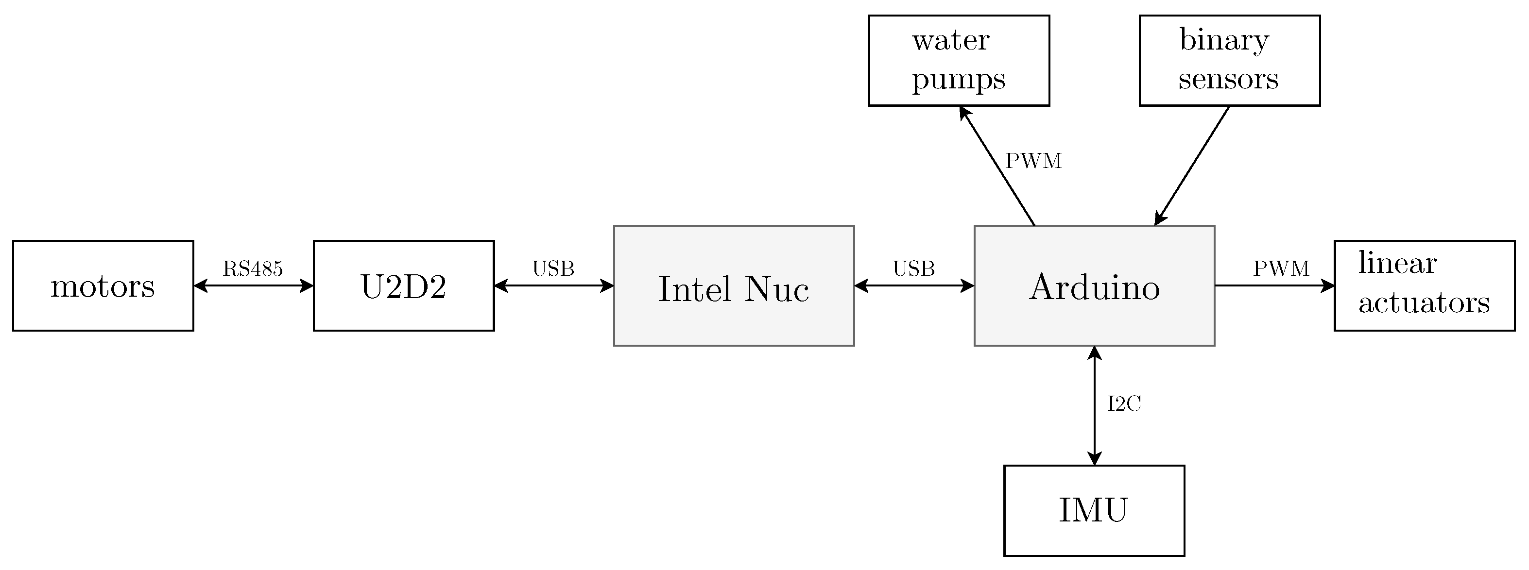
The design of our robot has the form of a multipod with five legs, as seen in Figure 1. Its body is composed of two carbon fiber pentagonal plates with trimmed corners, between which all the electronics necessary for the robot’s operation are housed. The legs are attached to the corners of these plates. The body is detailed in Figure 2. The robot’s main hardware components are summarized in Table 1. The schematical representation for connections between these components as well as some peripheral components is presented in Figure 3.
The distance from the center of the body to the insertions of the legs is 15 cm. A small water reservoir with a capacity of about 0.5 L is mounted on top of the body, along with two pumps for watering plants. A third pump, located inside the second segment of the third leg, is used for refilling the water reservoir when it is empty. Under the body, there is a mount for the battery. The total mass of the robot is 10 kg.
The legs are attached to the body so that there is equal spacing between them. Since the robot does not significantly change its orientation while climbing a wall, the legs are numbered from 1 to 5, with the leg at the top of the body (when viewed in a vertical position) marked as 1, followed by the others in a counterclockwise direction.
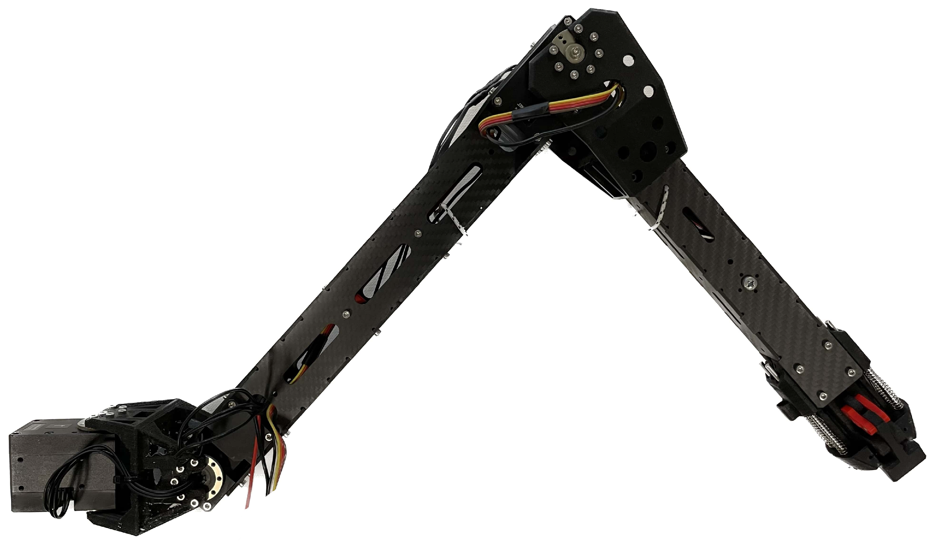
The leg is shown in Figure 4 and can be compared to a serial robot with three degrees of freedom. It has three rotational joints connected by segments of different lengths, and a special two-fingered gripper at the end. The first leg segment is made of nylon with glass fibers, the second of carbon fibers, and the third of both materials. The first segment is short, serving only to connect the first and second motors. The second and third segments are shaped like hollow rectangles to allow for wiring to the motors and grippers. A linear actuator for controlling the gripper is located inside the third segment. The theoretical kinematic limits for each joint are ± 80 for the first joint, ± 90 for the second joint, and ± 130 for the third joint. For reference, this corresponds to a range of motion of 35 cm (from the leg being completely flexed versus completely extended). The dimensions and masses of the segments, from first to last, including the motors and the gripper, are listed in Table 2.
The mass of the first motor is not included in the first segment’s mass, as it is attached to the robot’s body and does not affect the leg’s dynamics. The second and third motors are part of the second segment. The third segment, extending from the second joint to the end, also contains the gripper. The mass of the second segment, shown in parentheses, refers to the second segment of the third leg, which houses a pump for filling the reservoir. In addition to moving the robot, the second and fifth legs are used for watering plants, and the third leg for filling the reservoir. For this purpose, silicon tubing is run from the pumps to the reservoir or the ends of these legs.
The grippers are designed to grasp specific holds on the green wall. A hold consists of a steel screw with a 12 mm diameter ball at the end, as shown in Figure 5 in the middle. Consequently, the gripper is made of a half-spherical cavity of the same diameter (Figure 5, right). This allows the gripper to fit nicely onto the hold. Additionally, two fingers are mounted on the gripper, controlled by a linear actuator. The linear movement of the actuator is transformed into rotational movement of the fingers around a pivot point on the gripper body. When the linear actuator extends, the fingers close and grasp the hold without any gap. The finger mechanism is designed so that it goes through a kinematic singularity when closing. This means that the fingers cannot be opened except by moving the linear actuator. This ensures that the robot remains on the wall even if there is a full loss of power on the robot. Such a configuration of the gripper can also be considered a passive spherical joint, allowing rotations around all axes. This enables the movement of the spider in the manner of a parallel robot. Inside the body of the gripper on the surface contacting the ball, there is a mechanical switch for providing feedback as well as a spring-loaded contact for enabling power delivery through the steel screw and ball assembly. Figure 5 also shows part of the last leg segment where the linear actuator is located.

2.3. Motion Planning

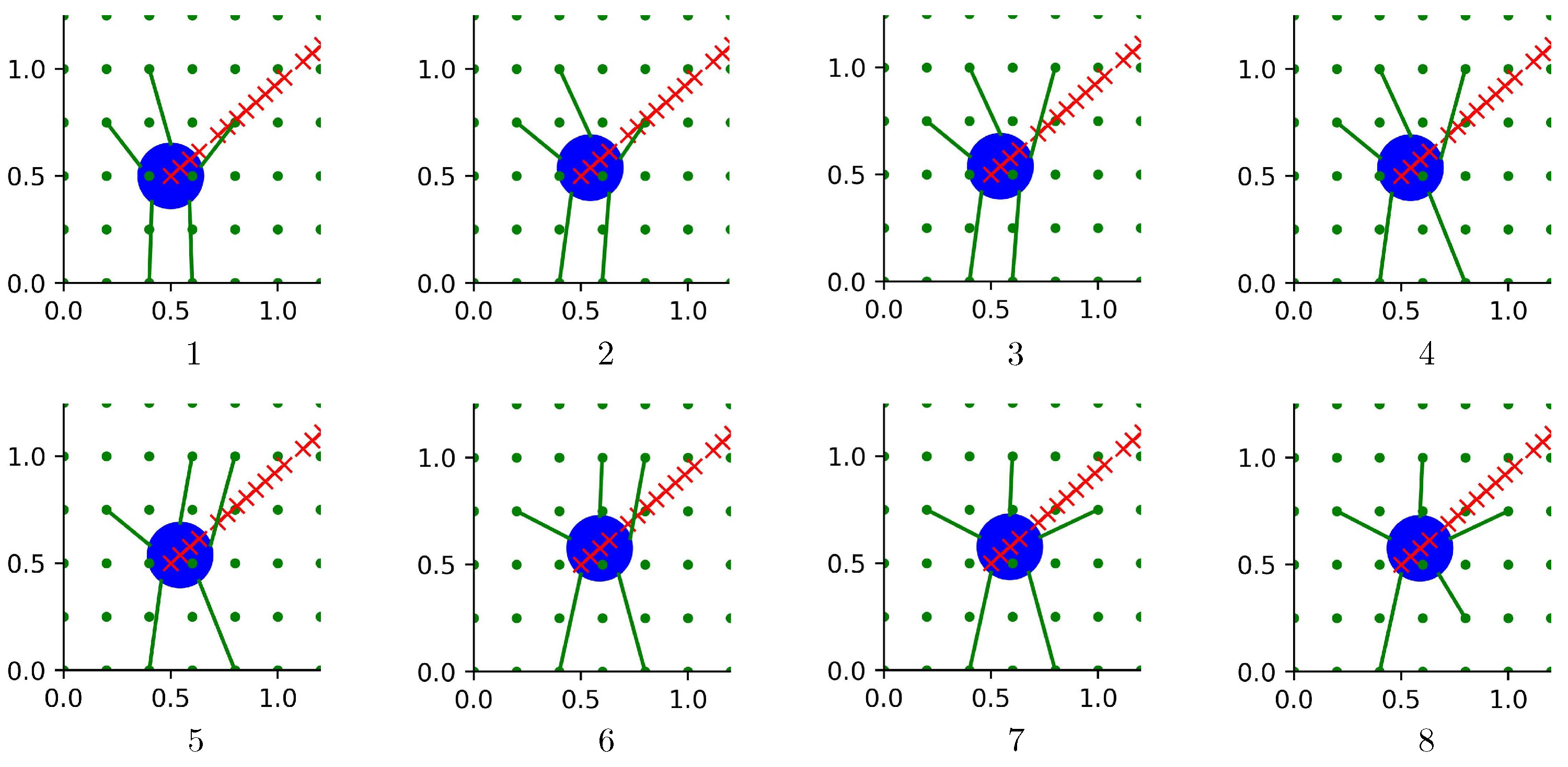
In the following section, the method used for planning the robot’s motion along the wall will be presented. Our goal is to move the robot from point A to point B on the wall and repeat this throughout its operating time. Points A and B are determined by the robot’s current position and the positions of the plants on the wall that need watering. However, for the robot to move along the wall, it must alternately perform two types of movements: (i) body movement when all legs are attached to the wall (movements between 1–2 and 5–6 in Figure 6) and (ii) movements of individual legs from one hold to another (movements on 2–5 and 7–8 in Figure 6). Thus, a single walking cycle consists of moving the body and then moving the legs. The distance covered in a single body movement and the number of leg movements in each cycle are not constant, as they depend on the robot’s position on the wall and the positions of the holds it is currently using and those it will use in the next step.
The body movements are carried out as the movement of a parallel robot, where all five legs participate, while the movements of individual legs from one hold to another are equivalent to the movement of a serial robot. The body travels in a straight line between the starting and ending points. When any one of the legs reaches the edge of its workspace, the body stops, and the robot moves its legs (each separately) to the next holds. Then, the body continues with its movement.
First, we define the path of the body along the line between the starting and ending points. We discretize this path into individual points lying on this line, as shown by the red points in Figure 6. For each point, we determine the ideal configuration of the legs in the sense of minimizing the load in the robot joints. This means the ideal set of five holds that the legs will use when the body reaches that point on the path. It may happen that several consecutive points have the same ideal configuration of legs. In this case, the body moves continuously across all these points. In planning the overall movement of the robot between two points on the wall, it is particularly important how we determine the holds that will be used along the way. The configuration of the legs greatly influences the load on the motors in the joints. There are leg configurations where relatively low torques in the joints are sufficient to support the robot on the wall, and conversely, leg configurations that may require (excessively) high torques from the motors. Naturally, we want the robot in configurations that require the least possible load on the motors.
After dividing the path of the body into individual points lying on the line between the starting and ending point, we must determine for each point the leg configurations in which the loads on the motors in the joints will be minimized. Our method is inspired by the way humans climb. While climbing, people try to keep their arms as extended as possible, as this allows most of the weight to be borne by the skeleton and not the muscles. The robot cannot fully extend its legs, as this would cause singularity. However, it can come as close to this as possible.
The selection of holds occurs in two steps: (i) in a wider selection of potential holds are all those within the reach of the leg. The reach of the leg is limited by the angle of rotation in the first joint and by the minimum and maximum distance between the end-effector and the base of the leg; (ii) for each potential hold, we then calculate a criterion function
C = K y · ( p n i y G p b i y G ) + 1 | p n i x G p b i x G | + 10 5 + C x ,
where p n i x G and p n i y G are the x and y coordinates of the position of the end-effector, respectively, and p b i x G and p b i y G are the x and y coordinates of the position of the base of the leg, respectively. Both are expressed in the global coordinate system G. We select the hold that has the highest value of the criterion function. K y and C x are dependent on the individual leg, namely
K y = 5 , if i ( 1 , 2 , 5 ) 1 , if i ( 3 , 4 ) ,
where i is the leg’s index and
C x = 1 | Δ x | + 10 5 , if i = 1 1 | Δ x | + 10 5 , if Δ x 0 0 , if Δ x > 0 1000 , if p n i x G = p n 1 x G , if i = 2 1 | Δ x | + 10 5 , if Δ x 0 100 , if Δ x > 0 , if i = 3 100 , if Δ x < 0 1 | Δ x | + 10 5 , if Δ x 0 , if i = 4 0 , if Δ x < 0 1 | Δ x | + 10 5 , if Δ x 0 1000 , if p n i x G = p n 1 x G , if i = 5 ,
where Δ x is the distance between the leg’s base and the end-effector in the x direction of the coordinate system R. We plan the movement so that the coordinate systems R and G are aligned. Thus, gravity acts in the negative direction of the y axis of both coordinate systems. The first term of Equation (1) rewards holds where the legs are as extended as possible in the y direction, with a higher reward for the upper legs than for the lower legs. The second term rewards holds whose x coordinate is as close as possible to the x coordinate of the base of the leg. The third term serves for a more precise selection of holds. In the case of the upper-middle leg ( i = 1 ), its function is equal to the second term. For the case of the upper lateral legs ( i ( 2 , 5 ) ), the term imposes a high penalty (−1000) for cases where the potentially selected holds of the lateral legs would be the same as the selected hold of the middle upper leg. This penalty prevents the robot from wanting to grasp the same hold with two legs. The other two conditions for the upper lateral legs reward holds that are as close as possible in the x direction to the base of the leg, but they reward more so those holds that are on the outer side of the legs. The same applies to the lower legs. A penalty (−100) is assigned to holds that lie on the inner side of the lower legs in the x direction. The criterion thus selects such holds for each leg that they do not overlap, are as extended as possible in the y direction, and as close together as possible in the x direction. Different values of K y for the upper and lower legs cause the lower two legs to be slightly more separated in the x direction. In this way, it is easier to compensate for the torques acting on the robot around the y axis.
The described method represents the highest level of control in our three-level control mechanism (the other two levels (middle and lower) are explained in Section 2.6). Its outputs are a list of positions of the robot’s body on the path between two points on the wall and a list of legs configurations for each individual position of the body. During the execution of walking, positions from both lists are relayed to the controller, which executes the movements, meaning the parallel movements of the robot’s body and the individual legs’ movements from one hold to another.

2.4. Kinematic Analysis

To calculate the robot’s pose on the wall, we will assume that we know the positions of the holds on the wall that the robot is currently using. This is always the case since the grid of holds is fixed and known. For the calculation, we will use three legs that are holding the holds; those that are not attached are not considered for this calculation. Later, we can apply this calculation to all possible combinations of three different legs that are currently attached and then average the results. The only limitation is that the selected three legs’ end-effectors should not lie on the same line. The approach we will use to calculate the robot’s pose is similar to that used for calculating the forward kinematics of a parallel robot. We will determine the external coordinates, meaning the position and orientation of the robot in the global coordinate system, based on internal variables, specifically, the values in the joints of the selected legs, while also knowing the positions of these legs’ end-effectors in the global coordinate system.
In the calculation, we will use the scheme shown in Figure 7. We start by using the forward kinematics of individual legs to calculate the positions of all three selected legs’ end-effectors in the coordinate system attached to the center of the robot’s body, denoted as R. Transformation between the R system and the leg’s end-effector is represented as 4 × 4 homogeneous transformation matrix, representing the pose of the leg’s end-effector expressed in the R coordinate system. For our purposes, only the positional part is relevant, which we denote as vectors p n 1 R , p n 2 R , and p n 3 R . Furthermore, we determine vectors that point from the global coordinate system G to the holds gripped by the selected legs. These vectors simultaneously represent the global positions of the selected legs’ end-effectors. We denote them as p n 1 G , p n 2 G , and p n 3 G (only p n 1 G is shown in Figure 7 for clarity). The entire calculation is facilitated by the fact that the holds, and consequently the selected legs’ end-effectors, lie in the same plane. First, we determine the rotation of the coordinate system R relative to G. Then, we use this rotation to calculate the robot’s position in the coordinate system G. The normal of the plane is determined as follows:
n R = p n 1 , 2 R × p n 1 , 3 R ,
where
p n 1 , 2 R = p n 2 R p n 1 R , p n 1 , 3 R = p n 3 R p n 1 R .
The obtained normal is expressed in the coordinate system R and points in the same direction as the z axis of the coordinate system G. Now, in the coordinate system R, we express the remaining axes of the coordinate system G and write them with unit vectors
e z R = n R n R ,
e x R = p n 1 , 2 R p n 1 , 2 R ,
e y R = e z R × e x R ,
P R = e x R e y R e z R .
Now we have obtained the axes of the coordinate system P R expressed in the coordinate system R. The x and y axes of this system lie in the same plane as the x and y axes of the coordinate system G, and the z axes of both systems are aligned. It is necessary to rotate it around the z axis to align the x and y axes of both coordinate systems. The required rotation angle is determined from the vectors of the global positions of the legs’ end-effectors
ϕ = a t a n p n 1 , 2 y G p n 1 , 2 x G ,
p n 1 , 2 G = p n 2 G p n 1 G ,
where we introduced the auxiliary vector p n 1 , 2 G , which points from the hold of the first leg to the hold of the second leg. Now, we can construct a rotation matrix for rotation around the z axis and use it to align the obtained system with the G system
Rot z = c o s ( ϕ ) s i n ( ϕ ) 0 s i n ( ϕ ) c o s ( p h i ) 0 0 0 1 ,
R rot G = Rot z 1 · P R .
The matrix R rot G tells us how the coordinate system R is rotated relative to the coordinate system G. Now, using the known positions of the legs’ end-effectors in G and R, as well as the matrix R rot G , we can determine the positional part of the coordinate system R expressed in the coordinate system G. In this way, we can obtain the complete transformation between G and R, or in other words, we can determine the full pose of the robot in the global coordinate system. We denote the positional vector as p r G and it is calculated as
p r G = p n 1 G + R rot G · ( p n 1 R ) .
For the final calculation, considering just one leg is sufficient. However, to achieve better accuracy, we used the calculations for all three legs and averaged the results. Now, we can assemble the complete transformation matrix that determines the pose of the robot in the global coordinate system
R G = R rot G p r G 0 1 × 3 1 .

2.5. Robot Dynamics

In the following chapter, we will describe the procedures we have used to calculate the dynamics of the robotic system. We will first separately address each leg and then the robot as a whole system. In the context of the dynamics of an individual leg, we will determine the forces acting on the leg’s end-effector from the torques in the joints. To precisely determine the forces acting on the end-effector when in contact with the environment, it is necessary to determine how much of the joint torques is needed to support the leg’s own mass, meaning to compensate for gravity. In the second part of the section, we will present a procedure for efficiently optimizing the torques in the joints to reduce the load on the motors. Finally, we will describe the process of offloading an individual leg, in which we will combine methods for compensating for gravitational forces and distributing forces among any number of legs.

2.5.1. Determining the Force on the End-Effector

The prerequisite for all subsequent calculations presented in this section is knowledge of the forces acting on the end-effectors. We calculate these forces through the joint torques and Jacobian matrices for each leg separately. Since we are interested only in the force that occurs upon contact with the environment, we must first determine the torques in the joints required solely to compensate for the gravitational forces acting on the leg. The remaining torques can be later used to calculate the mentioned force.
Calculating the torques in motors: The torques in the motors are directly dependent on the electrical current flowing through them, which can be measured directly. The function reflecting the torque–current relationship is typically provided by the motor manufacturers. In our case, it is nearly a linear function, which we have approximated with a second-degree polynomial
τ m ( I ) = 2.936 · I 0.178 · I 2 ,
where I represents the electrical current. We divide the torques in the motor into those for compensating gravity ( τ g ) and those resulting from the implied force on the end-effector ( τ e e ). Some of the torques in the motor also represent losses ( τ l o s s ), which we will neglect in later calculations
τ m = τ g + τ e e + τ l o s s .
Since we are interested in the value of the implied external force on the end-effector, we can express τ e e from Equation (17). Instead of τ m , we substitute the value from Equation (16)
τ e e = τ m τ g = 2.936 · I 0.178 · I 2 τ g .
Calculating the torques for compensation of gravitational force: Torques for compensating gravitational forces cannot be directly measured, but they can be determined through the robot’s dynamic model. The more accurate the model, the better the estimate of joint torques. The goal is to accurately determine the torques in the joints required solely for supporting the mass of the leg, as this allows us to precisely determine the remaining joint torques. To determine the dynamic model, we used the Newton-Euler method [26], which is a recursive method. In our case, we have simplified the described method slightly and neglected all terms related to accelerations (except for the gravitational acceleration) and velocities. This simplification does not introduce a significant error into the calculations since all leg movements are relatively slow, and the mass of the segments is small, resulting in small contributions due to inertia. In the following sections, we will present the calculations for our simplified dynamic model for each individual leg.
Since we have neglected the contributions from linear and angular accelerations and velocities, in the recursive forward we only need to calculate the gravitational accelerations of individual segments in their respective coordinate systems. Therefore, we must express the gravitational acceleration in the coordinate systems of the segments. For this purpose, we will predefine rotational matrices. We measure the gravitational acceleration g using the accelerometer sensor, which is installed in the robot’s body and provides gravitational acceleration in the robot’s coordinate system denoted as R. Consequently, all calculated forces at the end-effectors will also be expressed in this coordinate system.
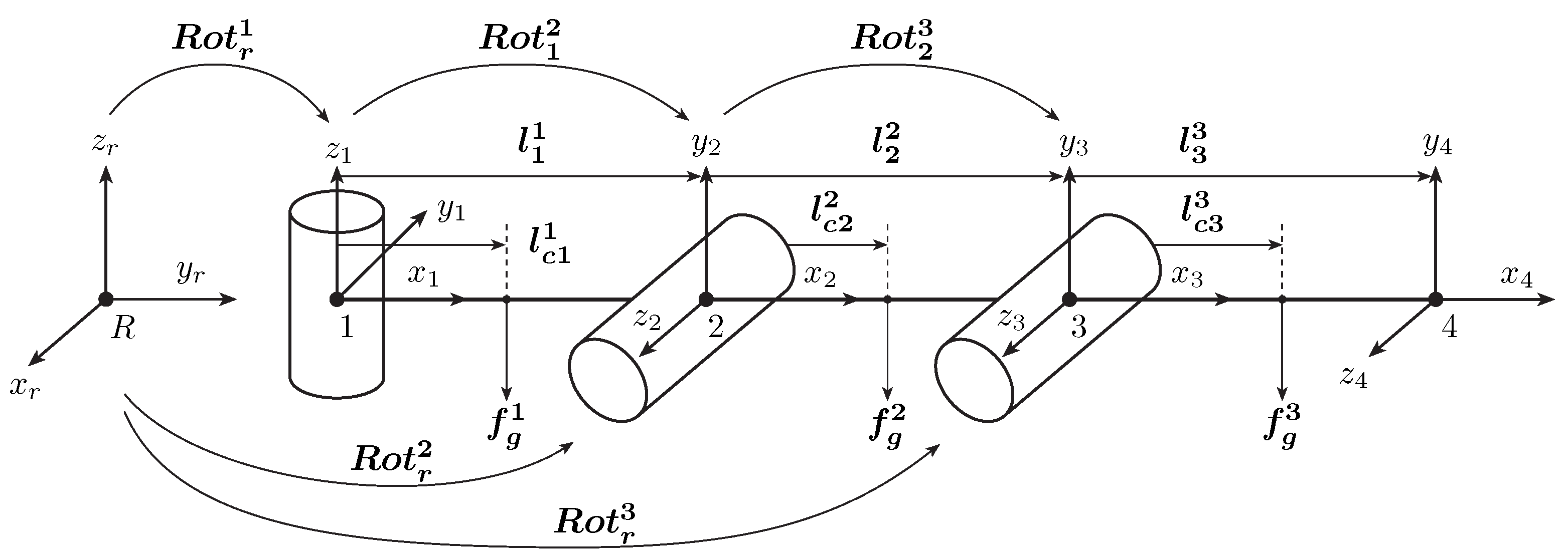
For assistance, we will use the diagram in Figure 8. Let us define the rotation matrices for rotations from the robot’s coordinate system into the individual segment systems.
Rot r 1 = c o s ( q r + q 1 ) s i n ( q r + q 1 ) 0 s i n ( q r + q 1 ) c o s ( q r + q 1 ) 0 0 0 1 ,
Rot r 2 = c o s ( q r + q 1 ) · c o s ( q 2 ) s i n ( q r + q 1 ) · s i n ( q 2 ) s i n ( q r + q 1 ) s i n ( q r + q 1 ) · c o s ( q 2 ) s i n ( q r + q 1 ) · s i n ( q 2 ) c o s ( q r + q 1 ) s i n ( q 2 ) c o s ( q 2 ) 0 ,
Rot r 3 = c o s ( q r + q 1 ) · c o s ( q 2 + q 3 ) c o s ( q r + q 1 ) · s i n ( q 2 + q 3 ) s i n ( q r + q 1 ) s i n ( q r + q 1 ) · c o s ( q 2 + q 3 ) s i n ( q r + q 1 ) · s i n ( q 2 + q 3 ) c o s ( q r + q 1 ) s i n ( q r + q 3 ) c o s ( q 2 + q 3 ) 0 ,
where with q r we denote the angle between the y axis of system R and the line that connects system R with the base system of the individual leg (in Figure 8 marked with ‘1’) whereby q 1 , q 2 , and q 3 are the angles in the joints. For each segment, which we denote with the index i, we therefore calculate the local gravity vector. Already in the recursion forward, we can use it to calculate the forces of gravity on individual segments f g i as
f g i = m i · Rot r i 1 · g ,
where m i represents the mass of the i-th segment.
We now follow the recursion backward, from the top of the robot towards the base. For this purpose, we prepare in advance the rotation matrices that represent rotations between the coordinate systems of the segments. We will need them to express the forces and torques with which the previous segment acts on the current one. The sum of all forces acting on a segment is the result of the forces with which the previous segment acts on the current one and the force of gravity, which we have already calculated in the forward recursion with Equation (22). Similarly, for the sum of all torques acting on the joint in the segment, which is the result of
-
torques of the previous segment,
-
forces of the previous segment, which through the lever represented by the length of the current segment ( l i i ), cause torques in the joint,
-
torque in the joint, which is a result of the force of gravity and the lever represented by the distance between the joint and the center of gravity of the segment ( l i c i ).
The exception is the first segment, where there are no influences from previous ones. We define the necessary rotation matrices
Rot 1 2 = c o s ( q 2 ) s i n ( q 2 ) 0 0 0 1 s i n ( q 2 ) c o s ( q 2 ) 0 ,
Rot 2 3 = c o s ( q 3 ) s i n ( q 3 ) 0 s i n ( q 3 ) c o s ( q 3 ) 0 0 0 1 .
Forces and torques in each segment or joint are calculated using the equations
f i i = Rot i i + 1 · f i + 1 i + 1 f g i ,
τ i i = Rot i i + 1 · τ i + 1 i + 1 + f g i × l i c i ( Rot i i + 1 · f i + 1 i + 1 ) × l i i ,
where l i is a vector that points from the beginning to the end of the i-th segment, and l i c is a vector that points from the beginning of the segment to its center of gravity. Both are expressed in the coordinate system that is placed in the joint of the corresponding segment.
In this way, through the dynamic model, we have determined the torques in all the joints of the leg. Since the calculation only considered gravitational accelerations, which are a result of the mass of the segments, the resulting torques are those that support this mass. Thus, we have obtained torques that suffice for the compensation of the force of gravity.
Calculating the force on the end-effector: Now, we have all the necessary terms to calculate the torques in the joints needed to support the external force on the leg’s end-effector, using Equation (18). This external force can be expressed by equation
F = ( J T ) 1 · τ ee .
As we see, we are dealing with the inverse of the Jacobian matrix. To avoid problems in singularity and its vicinity, we have used damped pseudoinverse, which is expressed as
J d # = J T · ( J · J T + a · I ) 1 ,
where a is the damping factor that is usually chosen as a small value (e.g., 0.001) and I is the identity matrix.
Now, we can insert the obtained damped pseudoinverse of the leg’s Jacobian matrix into Equation (27) and thus calculate the forces acting on the end-effector.
f n i = J d i # T · τ ee i .

2.5.2. Optimal Distribution of Torques and Offloading of Each Individual Leg

In the following subsection, we will again consider the robot as a complete system with five legs. The methods described in the previous subsection, in combination with some others that will be presented later, will be used for optimizing torques in the joints and offloading individual legs.
We will consider the static state of the robot. In this state, the resultant forces and torques acting on the robot are equal to zero. This means that the legs produce such forces that fully support all external forces and torques acting on the robot. This equilibrium can be written as
F = i = 1 5 f n i R , M = i = 1 5 p n i R × f n i R ,
where F denotes external forces, M denotes external torques, and f n i R denotes the forces with which the legs’ end-effectors act on the environment. As the index R indicates, all forces are expressed in the coordinate system of the robot.
Forces f n i R at the end-effectors are a result of the torques in the joints. Due to redundancy, there are infinitely many combinations of torques in the joints that produce such forces as f n i R which satisfy Equation (30) [9]. This allows us to choose the optimal combination from this set. In our case, we are looking for a combination of minimal torques in the joints, as we do not want to burden the motors more than necessary.
The process for optimizing torques in the joints is as follows: first, from non-optimal torques in the joints, we determine all the forces and torques acting on the end-effectors. We then use these forces to determine the external forces and torques, as Equation (30) holds. For this purpose, we first define two matrices that determine how f n i R map into F and M [23]. We denote them as J f and J m and write them as
J f = 1 0 0 1 0 0 0 1 0 0 1 0 0 0 1 0 0 1 ,
J m = 0 p n 1 z R p n 1 y R 0 p n 5 z R p n 5 y R p n 1 z R 0 p n 1 x R p n 5 z R 0 p n 5 x R p n 1 y R p n 1 x R 0 p n 5 y R p n 5 x R 0 .
Both matrices have dimensions 3 × 3 · n , where n is the number of legs and in our case is equal to 5. If we combine both matrices into one, which we denote as J fm , and write the forces f n i R into one vector of dimension 3 · n × 1 , we can write Equations (30) with a single Equation as
W = F M = J fm · f n R ,
where
J fm = J f J m
and
f n R = f 1 x R f 1 y R f 1 z R f 5 x R f 5 y R f 5 z R T .
Since we want to optimize the torques in the motors, we need to express the forces f n R in Equation (33) using Equation (29). However, as the latter applies only to one leg, we need to adapt it, as we want to calculate the entire vector of forces on the end-effectors, which has dimensions 3 · n × 1 . To do this, we combine all the damped pseudoinverses of the Jacobian matrices of individual legs into a diagonal matrix of dimension 3 · n × 3 · n
J d # T = J d 1 # T 0 3 × 3 0 3 × 3 0 3 × 3 J d 2 # T 0 3 × 3 J d 5 # T .
Now, we can write Equation (29) in a form suitable for calculating the forces on all end-effectors.
f n R = J d # T · τ ee ,
where τ ee is the vector into which we write all the torques in the motors
τ ee = τ e e 1 1 τ e e 1 2 τ e e 1 3 τ e e 2 1 τ e e i j T ,
where i represents the index of the leg and j represents the index of the motor or joint in the leg. Now, we can insert Equation (37) into Equation (33) and obtain an expression that provides a direct relation between the torques in the joints and the external forces and torques acting on the robot
W = J fm · J d # T · τ ee = J r · τ ee .
This equation will be the starting point for the optimization of torques in the joints described in the following section.
Optimization of torques: As already mentioned, we do not want to burden the motors in the joints more than necessary. Therefore, with optimization, we aim to minimize the sum of the squares of the differences between the external forces and torques and the forces and torques that are a result of the torques in the joints and compensate for the external force, which we write as
m i n J r · τ ee W .
Consequently, we minimize the variance of torques in the joints. This ensures that the motors are as evenly loaded as possible, while the optimized torques still provide forces at the end-effectors that satisfy Equation (30). We write the optimized torques using the pseudoinverse of the matrix J r , as
τ ee opt = J r T · ( J r · J r T ) 1 · W .
The obtained torques τ ee opt can now be inserted into Equation (37) to obtain redistributed forces, which can be implied to the end-effectors with our control algorithm, which will be presented in detail in Section 2.6.
Offloading of individual leg: Consider a scenario where the robot is in a static state and attached with all five legs to a wall. Each leg bears a part of the force that supports the robot and maintains its static state. However, for the robot to move along the wall, it needs to detach a specific leg at a given moment and move it to another hold. The problem that arises during such a movement is that the other legs do not take over the part of the force carried by the leg being detached in time, but only after it has already been detached. As a result, the leg does not detach smoothly but jerks strongly, since it is pressing with a certain force against the hold from which it has moved away, causing the robot to sag. The solution is to redistribute the forces among the remaining four legs, which will remain attached to the holds during the movement of the chosen leg, before moving that leg. The force necessary to keep the robot in a static state will thus be redistributed from five to four legs. The force at the end-effector of the leg that we want to move will drop to zero. Only in this case will the leg detach smoothly from the hold, and the robot will not sag during this process.
The process is similar to the one described in Section 2.5.2, but with a slight modification: first, using Equation (33), we determine the external forces and torques W that the legs must support. In the next step, we want to determine the optimal torques in the joints, such that the four legs, which will remain attached to the holds during the movement of the fifth, will act with such forces f n R that satisfy Equation (30). The torques in the leg that the robot will move will only serve to compensate for the force of gravity. Thus, this leg’s end-effector will not exert any additional force on the environment. Remember that for each torque in a joint, Equation (17) applies, where we ignore the torques for compensation of losses. For the leg that we are offloading, we want the torques in the joints to act solely for compensating the force of gravity, so the torques τ ee in this leg must be equal to zero. If we offload the first leg, the value of the optimized torques τ ee is equal to
τ ee opt = 0 0 0 τ e e 2 1 τ e e 2 2 τ e e 2 3 τ e e i j . T
To obtain the optimal torques τ ee opt using Equation (41), we need to rearrange the matrix J r so that we fill in the correct columns of the matrix with zeros (if we are offloading the first leg, these would be the first three columns; for the second leg, it would be the fourth, fifth, and sixth column, and so on). The resulting torques will imply forces on the corresponding legs’ end-effectors while still satisfying the condition expressed by Equation (30). However, these forces will only be borne by four legs, and no external force will act on the end-effector of the fifth leg. The robot can release this leg from its hold without affecting the other legs.

2.6. Robot Control

In this section, we will present the various control algorithms used in our robotic system. At any given time during the operation of the robot, the required type of movement is determined by the high-level controller presented in Section 2.3. These movements include the following:
  • the movement of the spider’s body
  • force redistribution over all the legs
  • movement of a single leg
  • approach to the hold and attachment of the leg to the wall
  • auxiliary single -leg movements for watering the plants or recharging the water reservoir
To execute these movements, we had to develop several different modes of the mid-level controller. We refer to these control modes as
  • position control mode,
  • force control mode,
  • velocity control mode.
The final output of any of these mid-level controller modes is a commanded velocity for each motor. This commanded velocity is the input to the low-level control that is embedded in the motor itself in the form of a tuned PID controller.
In the following subsections, we will provide a detailed description of all three control modes. We will start with position control, as it is the basis for the other two.

2.6.1. Position Control Mode

Position control is used when we want to move a leg from one grip to another or when we want to move the entire robot’s body by synchronously moving all five legs.
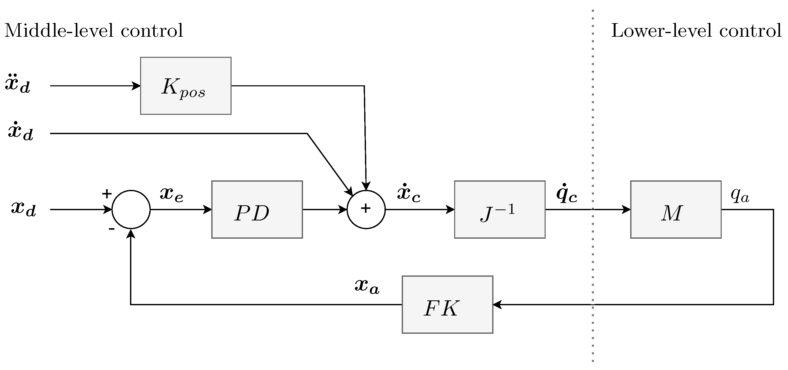
The diagram in Figure 9 represents the model of a position controller [27]. For a better understanding, the diagram includes the lower level of control, where M represents the robot’s mechanism that moves using motors in the joints. The label PD represents the PD controller, and FK is the forward kinematics of the leg.
We provide the reference as the desired position of the end-effector x d . We obtain feedback information about the joint angles from the motors q a . In the feedback loop, using forward kinematics, we calculate the actual positions of the end-effector. By subtracting the desired and actual positions, we obtain the position error of the end-effector x e , which is the input to the position PD controller. We then add the previously calculated velocities x ˙ d and accelerations x ¨ d . The sum of all three is the commanded quantity, which in our case represents the velocity of the end-effector. Using the inverse Jacobian matrix of the leg, we calculate the required joint velocities from the velocity of the end-effector, which we can send to the motors. Desired positions, velocities, and accelerations are obtained by calculating position trajectory (either minimum jerk or bezier trajectory, depending on the type of movement) and its first and second derivatives. Such a controller allows us to smoothly follow the trajectory. In an ideal case, position PD control would not be needed. If the leg moved at the exact same velocity as calculated in the trajectory generation process at all times (i.e., the feed-forward process), the position error would be constantly zero, and the commanded quantity would contain only the pre-calculated components. Therefore, the position PD term regulates errors that occur due to external influences and prevents the end-effector from being in a position not dictated by the trajectory at any given moment. The pre-calculated acceleration, multiplied by the constant K p o s , serves for a smoother transition at the beginning or end of the movement.

2.6.2. Force Control Mode

We primarily use force control mode to unload an individual leg before it makes a transition from one grip to another. Mathematically, the process of calculating the required forces is presented in Section 2.5.2. Here, we will describe how force control is implemented in the controller which is presented in Figure 10.
The task of the force control regulator is to convert the desired force at the end-effector into a velocity with which the leg should move and the positional offset it needs to perform to achieve the desired force. We then pass the velocity and the offset of the end-effector to the position controller, as described in the previous subsection. This conversion is easiest to understand in the case where we want the force at the end-effector to be zero. If we apply an external force to the end-effector, the force error f e will be equal to f a ( f a represents the forces with which the leg acts on the surface; due to the action-reaction law, the external force has the same magnitude and opposite sign). The calculated velocity of the tip x ˙ d will cause the leg to start moving in the direction of the external force. In this way, the leg moves away, and the force acting on it decreases toward zero since the leg no longer resists the external force. The speed of the leg depends on the gain of the P-controller K f , and at high gains, even a small error will result in a large displacement. This provides greater leg compliance and faster adjustment of the force, but system stability must be ensured. Using the control loop period, denoted as T, we also calculate the positional offset x d from the velocity of the end-effector.
The reference is represented by the desired force at the end-effector f d . In addition to joint angles, the feedback information from the motors also contains the currents flowing through the motors. Through the process described in Section 2.5.1, we calculate the actual forces acting on the end-effectors, taking into account the gravitational acceleration g , measured with the IMU sensor. The force error f e , obtained as the difference between the desired and actual force, is sent to the P-controller with gain K f . The output of the P-controller is the velocity of the end-effector x ˙ d , which we multiply by the period T to obtain the positional offset x d . Velocity and offset are the inputs to the position controller described in Section 2.6.1. In force control mode, the element that introduces the pre-calculated acceleration x ¨ d into the position controller is set to zero.

2.6.3. Velocity Control Mode

In velocity control mode, we provide a reference as the desired velocity of the end-effector. In this mode, the leg moves in a specific direction until it receives a new command or until the force at the end-effector reaches a certain limit. This mode is quite similar to force control, with the only difference being how the reference is provided. We use velocity control mode when we want to achieve more precise movement in a particular direction, for example, when the leg misses a hold and requires correction. In such cases, the leg moves away from the wall by a few centimeters and then makes another approach attempt in velocity control mode. When it hits the hold, the force at the end-effector exceeds a certain threshold, causing the reference velocity to drop to zero. This prevents excessive motor loading.
We provide the reference as a unit vector representing the desired direction of end-effector movement. The unit vector is multiplied by a factor that determines the velocity magnitude. The new position of the leg is calculated by adding the velocity multiplied by the time step to the previous position. The calculated velocity and position are inputs to the position controller. This can be expressed with the following equations:
x ˙ d = e h N · K h · K m , x d = x a + x ˙ d · T ,
where e h N is the unit vector specifying the direction of motion, K h is the factor determining the velocity magnitude, and K m is defined as
K m = 1 if | f a | f m a x 0 otherwise
and causes the leg’s reference velocity to be zero when the force at the end-effector exceeds the allowed threshold f m a x . In the feedback loop, we require the current leg positions x a and the force at the end-effector f a .

3. Results

The operation of the robot in maintaining the vertical garden was evaluated in a real-world setting for a period of one month. During the evaluation, the robot successfully operated for approximately eight hours per day. For safety reasons, the robot was under human supervision. We were collecting data related to the performance of the robot during the last two weeks of the evaluation. Some of the most important statistical features of the collected data are presented in Table 3.
Alongside the main results of the performance of the robot system outside the lab, we present some more specific analyses we performed to validate the use of our control strategies.
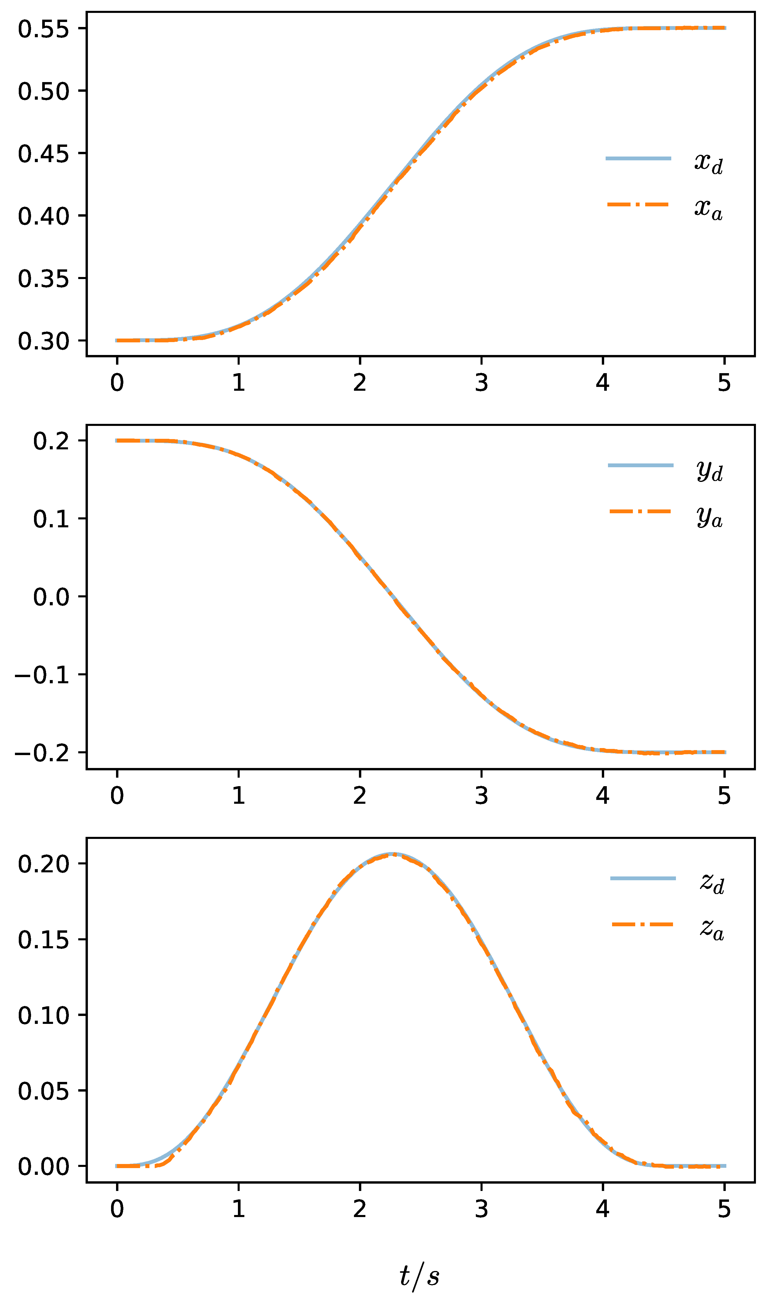
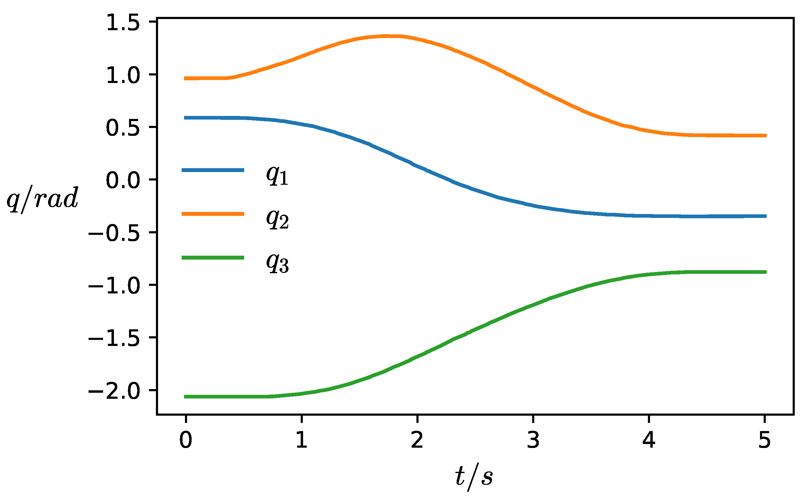
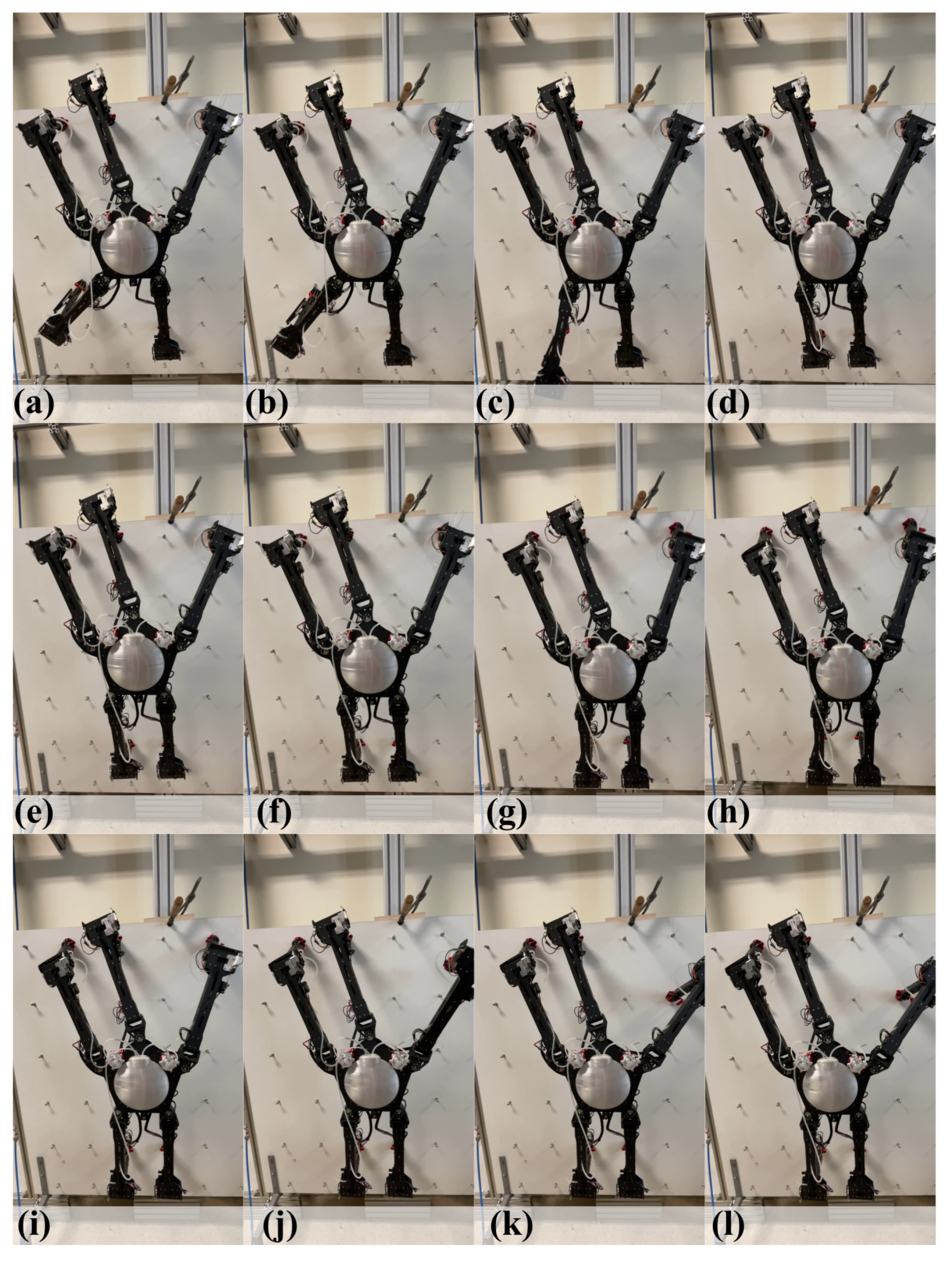
Example Movement: We present an example of a single leg movement between points P 0 = [ 0.3 , 0.2 , 0.0 ] and P 1 = [ 0.55 , 0.2 , 0.0 ] , given in leg’s local origin, with the specified duration of 5 s which corresponds to a leg movement going for one hold up and two holds sideways on the wall. Graphs in Figure 11 show the reference and actual positional trajectories of the leg’s end-effector. We can observe that end-effector movement is very stable and follows the reference trajectory without any overshoots or steady-state errors. The graph in Figure 12 shows the joint angles and Figure 13 shows the torques in the joints during this movement. A similar example for a whole-body movement was also recorded and the graphs for positions, joint angles, and torques for all legs are presented in the Supplementary Materials as Figure S1. For reference, the motor capabilities are a stall torque of 10.6 Nm and a no-load speed of 30 rev/min. This corresponds to a theoretical tip velocity of 1.8 m/s with a leg fully extended. However, typical peak velocities for leg movements during operation are around 0.2 m/s. Additionally, we also provide a frame-by-frame graphic for an example movement of the robot on a testing wall in Figure 14.
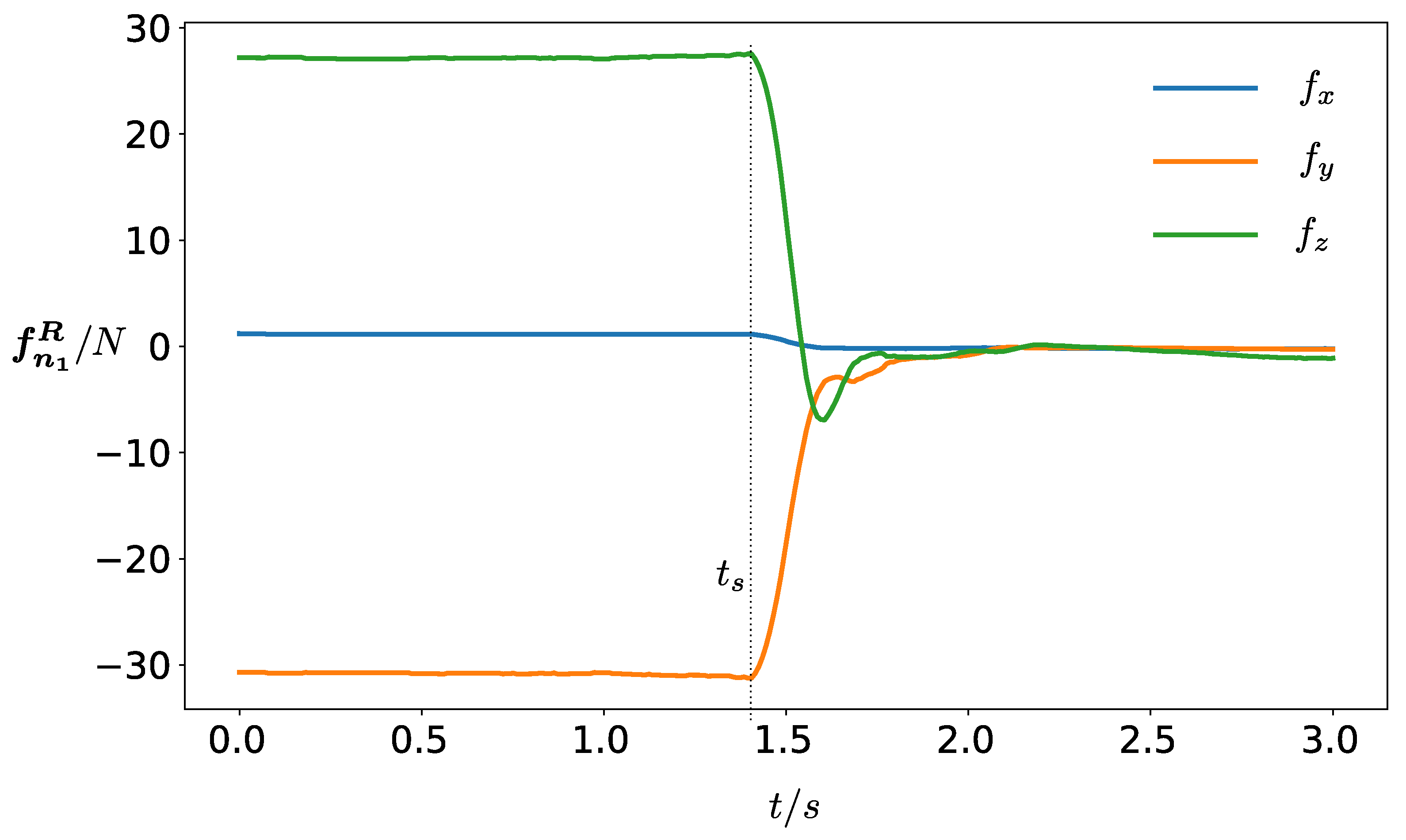
Interpretation of Unloading Results: Before explaining the graphs in Figure 15 and Figure 16, it is necessary to clarify the setup and orientation of the given quantities. The offloading process is carried out on the first (upper-middle) leg. The coordinate system of the robot R is aligned with the global coordinate system G. This means that the -y axis of system R points in the direction of gravity. The position of the first leg, expressed in the coordinate system R, is as follows:
p n 1 R = 0 p y p z .
Consequently, the force borne by the first leg also has a component in the x direction, approximately equal to zero. The y component of the force is due to gravity acting on the robot, and the z component is due to the torque caused by the mass of the robot, acting around the x axis of the coordinate system R.
The graph in Figure 15 shows the force f n 1 R on the first leg as a function of time, before and after offloading. Offloading begins at time t s . After a transient period, the force drops almost to zero, meaning that the leg no longer carries any part of the robot’s mass and can be detached.
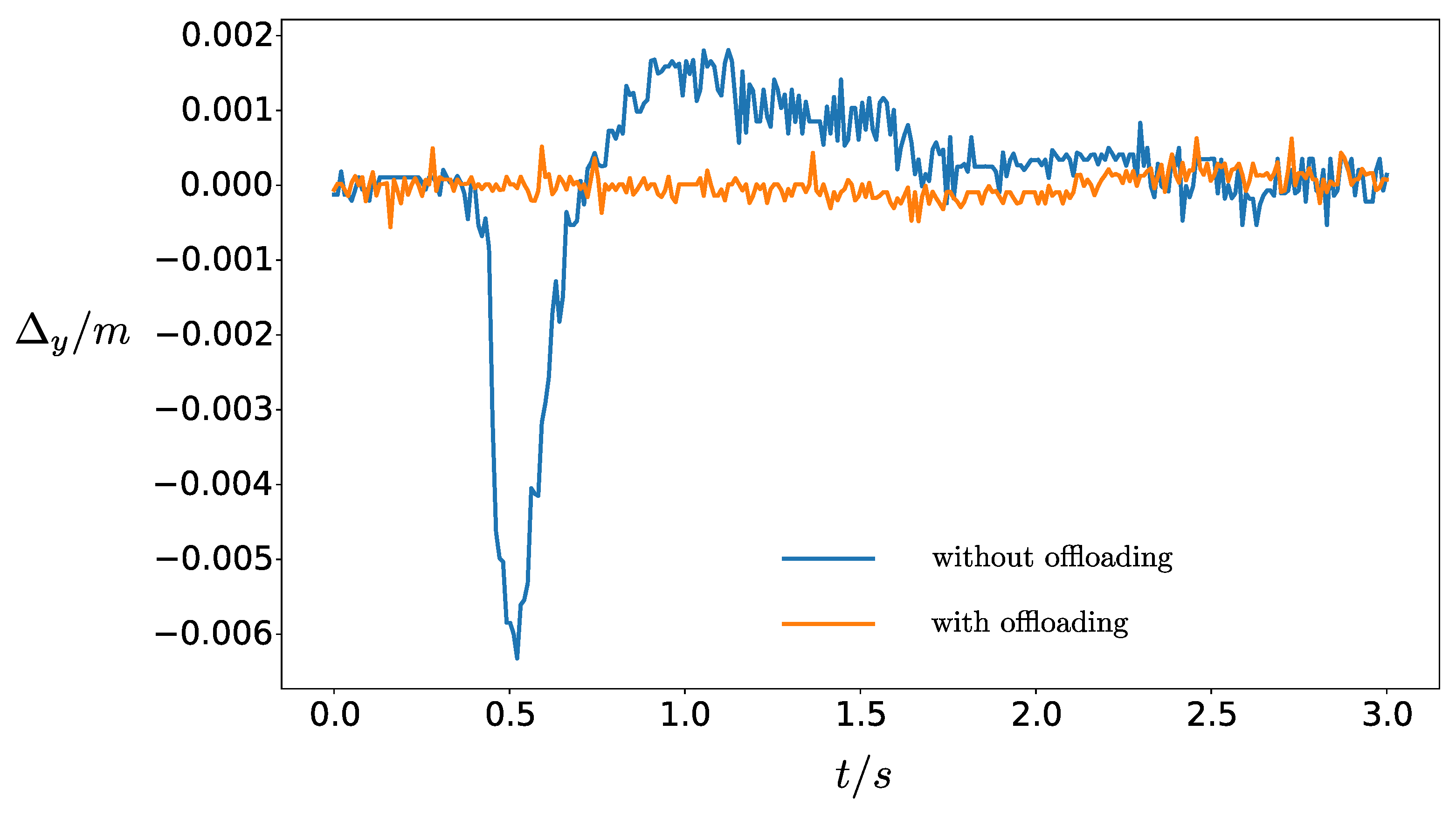
The graph in Figure 16 shows the leg sag, which occurs after detachment if the offloading procedure is not performed beforehand. The issue of this sag is also described in Section 2.5.2. The sag occurs in the direction of gravity and is shown on the graph by the blue curve. As we can see, there is no sag, if the leg was offloaded before detachment, as indicated by the orange curve on the graph.

4. Discussion

In our work, we developed a robot that can climb vertical walls with specialized holds. As this work was developed in collaboration with artists, their demands imposed several constraints (such as the number of legs of the robot, autonomy of the robot, and power delivery method), requiring us to find innovative theoretical and engineering solutions, including modifications to existing ones. We developed a cable-free power supply system using holds on the wall and specially designed grippers on the robot’s legs. The grippers could arguably be designed in a different way in order to grasp different holds or even incorporate the use of magnets or suction cups as in many other climbing robots [7,8,12,28]. However, in the scope of this work, the use of grippers with no self-locking capability in case of power loss was deemed too dangerous. This is because the robot was always operating without any backup power cables or safety tethers directly above a small pond of water and near humans. Due to the robot’s size requirements, we encountered issues with its heavy weight, causing motors in the joints to be constantly strained at their upper limits. This strain was further exacerbated by the robot’s rigid attachment to the holds on the wall with its legs. Even slight positional errors in leg movements create significant internal forces within the robot’s structure. To address these challenges, we developed and applied methods for distributing and optimizing torques in the joints. We also developed a control algorithm capable of controlling the robot both as a parallel, while moving its body, and as a serial mechanism, while moving individual legs. This controller also implemented various methods for inputting reference commands, as described in Section 2.6. The success of each leg movement from one hold to another depends on knowing the robot’s global position on the wall. Due to the use of the robot outside of a laboratory setting, we could not use any external positioning systems. The immeasurable sag in the structure and motors make calculating the robot’s global position inaccurate. Therefore, the method used offloads the leg before moving it and provides the movement command as a positional offset between two holds, instead of absolute position. During the robot’s operation at an exhibition, we collected basic data on leg movements. Despite the described solutions, human operator intervention was still required in 0.6% of movements, where the robot was unable to solve problems on its own. Most often, this was due to a piece of leaf or a plant covering the switch for detecting a successful grip, located inside the gripper on the robot’s leg. This caused the switch to give a false-positive signal, incorrectly informing the robot that the leg had successfully gripped. This problem could be solved by having the robot try to move the leg away from the grip after receiving a positive signal while simultaneously monitoring forces or currents in the motors. Another method would be for the robot to monitor the switch signal while the leg is on its way to the next hold. If the switch signals positive during this time, it is likely broken or stuck.
We did not include experimental data on the speed limits and the robot’s locomotion speed, including its leg movements. The determination of the robot’s walking speed on the wall is complex, as it hinges on various factors such as the speed of movement of individual legs, the number of required leg movements, and especially on the success of the movements. In case the leg movement is unsuccessful (i.e., it does not grasp a hold), the robot makes corrections until the hold is successfully grasped. Consequently, we did not focus on the analysis of speed. In the development of the robot, we prioritized the reliability of operation over speed itself. One of the main goals was to create a robot capable of long-term autonomous operation by using specially designed grippers and holds on the wall through which it is powered. In the event of a fault in the mentioned power supply system (e.g., a piece of plant covers the contact in the gripper), the battery installed on the robot can power the robot for about 30 min. In the event of such a fault, the robot detects it on its own, ceases operation, and goes into a so-called resting-pose, where it waits for a human operator.
The robot was primarily designed as an artistic work, intended for displaying a prototype of an automated vertical garden. We recognize that as such, it is not capable of directly generalizing to different use cases primarily due to the specific nature of the power delivery system. Nevertheless, the developed mechanical and software solutions, as well as the control solutions for such a robot, are useful and can be transferred to other, similar mechanisms, especially in the field of robotic multipods and climbing robots [29].

Supplementary Materials

The operation of the robot on the full scale wall can be seen at the following link: https://kons-platforma.org/en/projekti/stellaverde/ (accessed on 25 December 2023). The following supporting information can be downloaded at the following link: https://www.mdpi.com/article/10.3390/machines12020141/s1, Video S1: Design and Control of a Climbing Robot for Autonomous Vertical Gardening. Figure S1: Collection of graphs during an example whole body spider movement on the test wall.

Author Contributions

Conceptualization, M.J., G.S. and J.B.; methodology, M.J., G.S. and J.B.; software, G.S.; validation, M.J.; formal analysis, G.S.; investigation, M.J., G.S. and J.B.; resources, J.B.; data curation, G.S.; writing—original draft preparation, M.J. and G.S.; writing—review and editing, M.J, G.S., J.K. and J.B.; visualization, M.J. and G.S.; supervision, J.B.; project administration, J.B.; funding acquisition, J.K. and J.B. All authors have read and agreed to the published version of the manuscript.

Funding

This work was partially supported by the Slovenian Research Agency (research core funding no. P2-0076); by the European Commission’s Directorate-General for Communications Networks, Content, and Technology under grant agreement LC01641664; by the Ministry of Culture Republic of Slovenia; and by the European Regional Development Fund of the European Union.

Data Availability Statement

The original contributions presented in the study are included in the article and supplementary material.

Conflicts of Interest

The authors declare no conflicts of interest.

References

  1. Fang, Y.; Wang, S.; Bi, Q.; Cui, D.; Yan, C. Design and Technical Development of Wall-Climbing Robots: A Review. J. Bionic Eng. 2022, 19, 877–901. [Google Scholar] [CrossRef]
  2. Tao, B.; Gong, Z.; Ding, H. Climbing robots for manufacturing. Natl. Sci. Rev. 2023, 10, nwad042. [Google Scholar] [CrossRef] [PubMed]
  3. Klančar, G.; Zdešar, A.; Blažič, S.; Škrjanc, I. Chapter 1—Introduction to Mobile Robotics. In Wheeled Mobile Robotics; Klančar, G., Zdešar, A., Blažič, S., Škrjanc, I., Eds.; Butterworth-Heinemann: Oxford, UK, 2017; pp. 1–11. [Google Scholar] [CrossRef]
  4. Chen, S.; Cao, Y.; Sarparast, M.; Yuan, H.; Dong, L.; Tan, X.; Cao, C. Soft Crawling Robots: Design, Actuation, and Locomotion. Adv. Mater. Technol. 2020, 5, 1900837. [Google Scholar] [CrossRef]
  5. Bellicoso, C.D.; Bjelonic, M.; Wellhausen, L.; Holtmann, K.; Günther, F.; Tranzatto, M.; Fankhauser, P.; Hutter, M. Advances in real-world applications for legged robots. J. Field Robot. 2018, 35, 1311–1326. [Google Scholar] [CrossRef]
  6. Schmidt, D.; Berns, K. Climbing robots for maintenance and inspections of vertical structures—A survey of design aspects and technologies. Robot. Auton. Syst. 2013, 61, 1288–1305. [Google Scholar] [CrossRef]
  7. Bisht, R.S.; Pathak, P.M.; Panigrahi, S.K. Design and development of a glass façade cleaning robot. Mech. Mach. Theory 2022, 168, 104585. [Google Scholar] [CrossRef]
  8. Eto, H.; Asada, H.H. Development of a Wheeled Wall-Climbing Robot with a Shape-Adaptive Magnetic Adhesion Mechanism. In Proceedings of the 2020 IEEE International Conference on Robotics and Automation (ICRA), Paris, France, 31 May–31 August 2020; pp. 9329–9335. [Google Scholar] [CrossRef]
  9. Vidoni, R.; Gasparetto, A. Efficient force distribution and leg posture for a bio-inspired spider robot. Robot. Auton. Syst. 2011, 59, 142–150. [Google Scholar] [CrossRef]
  10. Silva, M.F.; Machado, J.A.T.; Tar, J.K. A Survey of Technologies for Climbing Robots Adhesion to Surfaces. In Proceedings of the 2008 IEEE International Conference on Computational Cybernetics, Stara Lesna, Slovakia, 27–29 November 2008; pp. 127–132. [Google Scholar] [CrossRef]
  11. Pack, R.; Christopher, J.; Kawamura, K. A Rubbertuator-based structure-climbing inspection robot. In Proceedings of the International Conference on Robotics and Automation, Albuquerque, NM, USA, 25–25 April 1997; Volume 3, pp. 1869–1874. [Google Scholar] [CrossRef]
  12. Ge, D.; Tang, Y.; Ma, S.; Matsuno, T.; Ren, C. A Pressing Attachment Approach for a Wall-Climbing Robot Utilizing Passive Suction Cups. Robotics 2020, 9, 26. [Google Scholar] [CrossRef]
  13. Unver, O.; Uneri, A.; Aydemir, A.; Sitti, M. Geckobot: A gecko inspired climbing robot using elastomer adhesives. In Proceedings of the 2006 IEEE International Conference on Robotics and Automation, 2006. ICRA 2006, Orlando, FL, USA, 15–19 May 2006; pp. 2329–2335. [Google Scholar] [CrossRef]
  14. Kim, S.; Spenko, M.; Trujillo, S.; Heyneman, B.; Mattoli, V.; Cutkosky, M.R. Whole body adhesion: Hierarchical, directional and distributed control of adhesive forces for a climbing robot. In Proceedings of the 2007 IEEE International Conference on Robotics and Automation, Rome, Italy, 10–14 April 2007; pp. 1268–1273. [Google Scholar] [CrossRef]
  15. Wang, Z.; Bao, G.; Zhang, L.; Yang, Q. Development and control of flexible pneumatic wall-climbing robot. J. Cent. South Univ. Technol. 2009, 16, 961–970. [Google Scholar] [CrossRef]
  16. Minor, M.; Dulimarta, H.; Danghi, G.; Mukherjee, R.; Tummala, R.L.; Aslam, D. Design, implementation, and evaluation of an under-actuated miniature biped climbing robot. In Proceedings of the 2000 IEEE/RSJ International Conference on Intelligent Robots and Systems (IROS 2000) (Cat. No.00CH37113), Takamatsu, Japan, 31 October–5 November 2000; Volume 3, pp. 1999–2005. [Google Scholar] [CrossRef]
  17. Haynes, G.; Khripin, A.; Lynch, G.; Amory, J.; Saunders, A.; Rizzi, A.; Koditschek, D. Rapid pole climbing with a quadrupedal robot. In Proceedings of the 2009 IEEE International Conference on Robotics and Automation, Kobe, Japan, 12–17 May 2009; pp. 2767–2772. [Google Scholar] [CrossRef]
  18. Nguyen, S.T.; Pham, A.Q.; Motley, C.; La, H.M. A Practical Climbing Robot for Steel Bridge Inspection. In Proceedings of the 2020 IEEE International Conference on Robotics and Automation (ICRA), Paris, France, 31 May–31 August 2020; pp. 9322–9328. [Google Scholar] [CrossRef]
  19. Webster, C.; Kong, F.H.; Fitch, R. Bio-inspired 2D Vertical Climbing with a Novel Tripedal Robot. In Proceedings of the 2022 IEEE/RSJ International Conference on Intelligent Robots and Systems (IROS), Kyoto, Japan, 23–27 October 2022; pp. 1239–1246. [Google Scholar] [CrossRef]
  20. Balaguer, C.; Gimenez, A.; Jardon, A. Climbing Robots Mobility for Inspection and Maintenance of 3D Complex Environments. Auton. Robot. 2005, 18, 157–169. [Google Scholar] [CrossRef]
  21. Kim, H.; Kang, T.; Loc, V.G.; Choi, H.R. Gait Planning of Quadruped Walking and Climbing Robot for Locomotion in 3D Environment. In Proceedings of the 2005 IEEE International Conference on Robotics and Automation, Barcelona, Spain, 18–22 April 2005; pp. 2733–2738. [Google Scholar] [CrossRef]
  22. Guan, Y.; Jiang, L.; Zhu, H.; Zhou, X.; Cai, C.; Wu, W.; Li, Z.; Zhang, H.; Zhang, X. Climbot: A modular bio-inspired biped climbing robot. In Proceedings of the 2011 IEEE/RSJ International Conference on Intelligent Robots and Systems, San Francisco, CA, USA, 25–30 September 2011; pp. 1473–1478. [Google Scholar] [CrossRef]
  23. Chen, X.; Watanabe, K.; Kiguchi, K.; Izumi, K. Optimal Force Distribution for the Legs of a Quadruped Robot. Mach. Intell. Robot. Control 1999, 1, 87–94. [Google Scholar]
  24. Huang, W.K.; Xiao, J.L.; Zeng, F.L.; Lu, P.W.; Lin, G.J.; Hu, W.; Lin, X.Y.; Wu, Y. A Quadruped Robot with Three-Dimensional Flexible Legs. Sensors 2021, 21, 4907. [Google Scholar] [CrossRef] [PubMed]
  25. Sun, Y.; Zong, C.; Pancheri, F.; Chen, T.; Lueth, T.C. Design of topology optimized compliant legs for bio-inspired quadruped robots. Sci. Rep. 2023, 13, 4875. [Google Scholar] [CrossRef] [PubMed]
  26. Khalil, W. Dynamic Modeling of Robots Using Newton-Euler Formulation. In Informatics in Control, Automation and Robotics; Cetto, J.A., Ferrier, J.L., Filipe, J., Eds.; Springer: Berlin/Heidelberg, Germany, 2011; pp. 3–20. [Google Scholar]
  27. Schaal, S.; Ijspeert, A.; Billard, A. Computational approaches to motor learning by imitation. Philos. Trans. R. Soc. Lond. Ser. B Biol. Sci. 2003, 358, 537–547. [Google Scholar] [CrossRef] [PubMed]
  28. Seriani, S.; Scalera, L.; Gasparetto, A.; Gallina, P. A new family of magnetic adhesion based wall-climbing robots. Mech. Mach. Sci. 2019, 68, 223–230. [Google Scholar] [CrossRef]
  29. Fang, G.; Cheng, J. Advances in Climbing Robots for Vertical Structures in the Past Decade: A Review. Biomimetics 2023, 8, 47. [Google Scholar] [CrossRef] [PubMed]
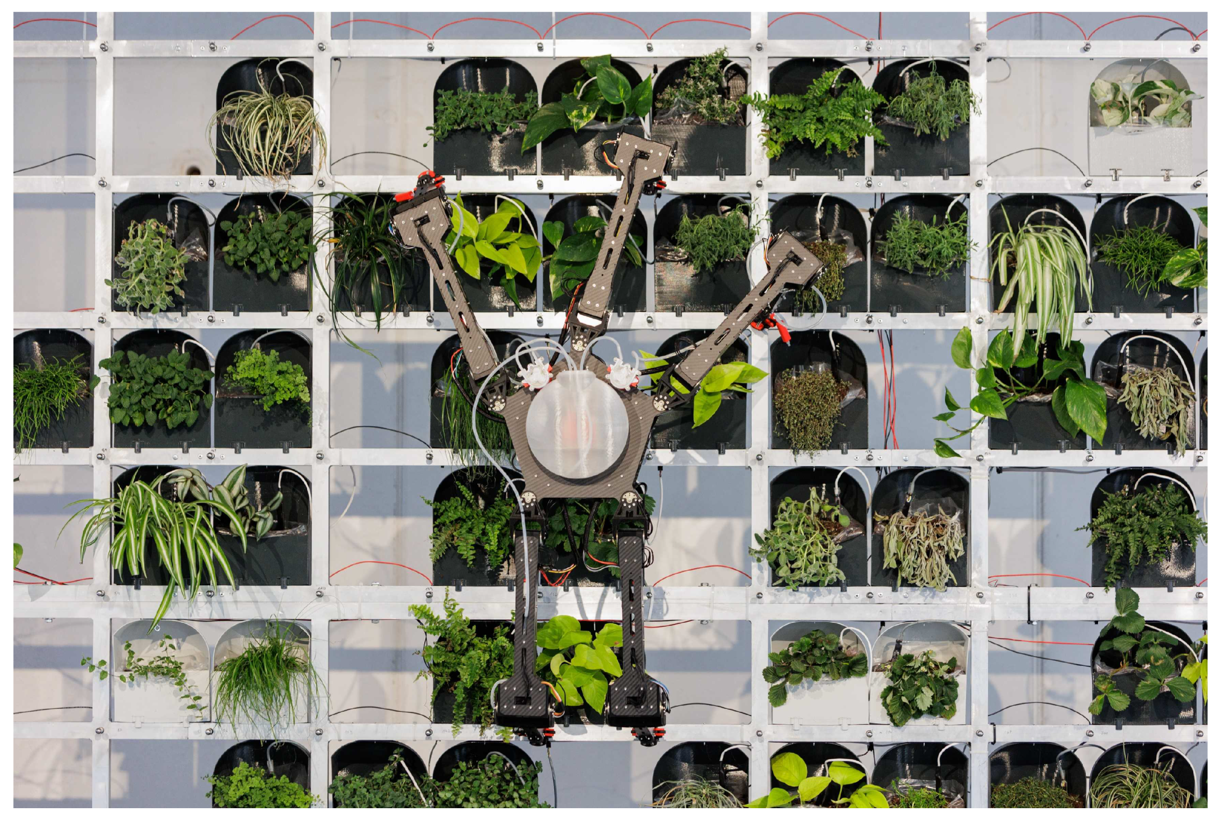
Figure 1. Robot during operation on green wall.
Machines 12 00141 g001
Figure 2. Robot body. 1—Water pumps for irrigation (the pump for filling the reservoir is situated inside the first segment of the third leg), 2—A water reservoir, 3—A motor in the first joint of the leg, 4—The upper body plate, 5—The lower body plate.
Machines 12 00141 g002
Figure 3. Schematic representation of connections between the main robot components. The main processing unit of the robot is the Intel Nuc computer. On one side it is connected to the motors with a USB cable via the U2D2 serial to RS485 converter. On the other side, it is connected to two Arduino Nano boards which provide an interface to the water pumps, binary sensors (mechanical switches), the IMU, and the linear actuators (grippers).
Machines 12 00141 g003
Figure 4. Closeup of one robot leg.
Machines 12 00141 g004
Figure 5. Gripper mechanism. 1—gripper fingers, 2—linear actuator, 3— hold, 4—mechanical switch, 5—spring-loaded contact for charging, 6—pivot point for the rotation of the finger.
Machines 12 00141 g005
Figure 6. Visualization of a sequence of movements needed to move the robot on the wall along the desired trajectory points (indicated by red crosses): 1–2 movement of the spider body to a new position, 2–5 movement of individual legs, 5–6 movement of the spider body to a new position, 7–8 movement of individual legs.
Machines 12 00141 g006
Figure 7. Diagram for calculating the robot’s position on the wall.
Machines 12 00141 g007
Figure 8. Diagram of the leg for calculating the Newton-Euler dynamics.
Machines 12 00141 g008
Figure 9. Position control diagram.
Machines 12 00141 g009
Figure 10. Controller diagram for force control.
Machines 12 00141 g010
Figure 11. Reference (blue lines) and actual (orange lines) trajectories of leg’s end-effector movement between points [0.3, 0.2, 0.0] and [0.55, −0.2, 0.0], given in leg’s local origin. The first subplot shows the x-coordinate, the second shows the y-coordinate, and the third shows the z-coordinate of the end-effector movement.
Machines 12 00141 g011
Figure 12. Angles in joints during the end-effector movement.
Machines 12 00141 g012
Figure 13. Torques in joints during the end-effector movement.
Machines 12 00141 g013
Figure 14. A collection of frames during an example movement of the robot on the wall. (ad) leg number three moving for one hold to the right and one down. (eh) whole body movement slightly down and right. (il) leg number five moving for one holds down.
Machines 12 00141 g014
Figure 15. Graph of force as a function of time during offloading.
Machines 12 00141 g015
Figure 16. Graph of leg sag as a function of time during offloading.
Machines 12 00141 g016
Table 1. Main hardware components and their manufacturers.
Hardware ComponentPart Name, Manufacturer
Main processing unitIntel NUC 11 NUC11PAHi7 (Intel corporation, Santa Clara, CA, USA)
Peripherals control boardArduino Nano (Arduino S.r.l., 20900 Monza (MB), Italy)
Motors for locomotionDynamixel XM430-W350-R (ROBOTIS Co., Seoul,
Republic of Korea)
Linear motors for grippersActuonix L12-30-50-12-I (Micro Linear Actuators & Servos—Actuonix Motion Devices, Victoria, BC, Canada)
Serial to RS485 converterU2D2 (ROBOTIS Co., Seoul, Republic of Korea)
Inertial measurement unit (IMU)GY-521 MPU6050 (InvenSense, San Jose, CA, USA)
Table 2. Lengths and masses of segments.
SegmentLengthMass
First segment6.4 cm57 g
Second segment30 cm620 (670) g
Third segment27.6 cm270 g
Table 3. Statistical features of data collected during the last two weeks of exhibition.
DescriptionData
Number of all leg movements7949
Number of successful 1st moves6604 (83%)
Number of successful 1st moves for each leg1: 74%; 2: 85%: 3: 98%; 4: 83%; 5: 78%
Human intervention needed49 (0.6%)
Disclaimer/Publisher’s Note: The statements, opinions and data contained in all publications are solely those of the individual author(s) and contributor(s) and not of MDPI and/or the editor(s). MDPI and/or the editor(s) disclaim responsibility for any injury to people or property resulting from any ideas, methods, instructions or products referred to in the content.