Abstract
Nomex honeycomb composite (NHC) cores have seen significant growth in recent years, particularly in the aeronautics, aerospace, naval and automotive industries. This development presents significant challenges in terms of improving machining quality, requiring the use of specialized cutting tools and favorable cutting techniques. In this context, experimental studies have been carried out to highlight the characteristics of the milling of NHCs by rotary ultrasonic machining (RUM). However, the rapid motion of the cutting tool and the inaccessibility of the tool/part interface prevent the visualization of the chip formation process. For this purpose, a three-dimensional numerical model for milling the NHC structure using RUM technology was developed by Abaqus Explicit software. On the basis of this model, the components of the cutting force, the quality of the machined surface and the chip accumulation in front of the cutting tool were analyzed. The numerical results agree with the experimental tests, demonstrating that the use of RUM technology effectively reduces the cutting force components. An in-depth analysis of the influence of feed component Fy on the quality of the generated surface was carried out, revealing that the surface quality improved with low values of feed component Fy. Furthermore, the impact of ultrasonic vibrations on the accumulation of chips in front of the cutting tool is particularly optimized, in particular for large amplitudes.
1. Introduction
A Nomex honeycomb composite (NHC) core is made from aramid fibers impregnated with phenolic resin. This combination gives Nomex honeycomb composites superior mechanical strength, increased toughness and excellent chemical resistance [1,2,3]. Due to their remarkable mechanical characteristics, NHC cores are widely used in the fields of aerospace and aeronautics, mainly in the manufacture of aircraft wings and tails [4,5,6,7]. However, the machining of NHC structures represents a major challenge for researchers and engineers due to the geometric complexity of thin-walled structures and the heterogeneous characteristics of Nomex paper. To meet these challenges, in-depth experimental studies are needed to understand and analyze the machining characteristics of NHC structures. These studies allow the analysis of the cutting process, while providing specific data to develop advanced numerical models aimed at analyzing cutting behavior and optimizing machining conditions [8,9]. An NHC core is generally machined using conventional methods, involving the use of cutting tools such as mills and lathes to remove material chips. However, despite the optimization of specially designed machining tools, the conventional machining process has significant shortcomings in terms of machining accuracy and the quality of the machined surface. In the fact, the problems with the machined surface of the NHC core manifest themselves in the form of burrs, cell deformation and the tearing of aramid fibers [10]. Consequently, conventional machining fails to deal effectively with these peculiarities, resulting in a poor machined surface. To overcome these problems, it is necessary to develop more advanced machining methods adapted specifically to the NHC structure, as well as to optimize the cutting conditions to minimize cell deformation and fiber pull-out. In response to these challenges, RUM technology was proposed to overcome the limitations of conventional machining process when processing NHCs. It is distinguished by the integration of ultrasonic vibrations along the axis of the tool, thus allowing better management of cell deformation and optimization of the cutting of the aramid fiber [11,12,13,14]. RUM technology has gained increasing interest in the machining of a variety of conductive and dielectric materials. These materials include titanium alloys [15,16], aluminum alloys [17,18,19,20], nickel alloys [21,22], glass [23,24], ceramics [25,26] and composites [27,28,29,30]. A study by Xia et al. [31] aimed to improve the structural design of an ultrasonic circular disc tool and to evaluate the effect of its geometrical characteristics on the energy density and stiffness of the tool. Their results indicated that the effectiveness of the NHC core treatment is highly dependent on the cutting angle, tool radius and vibration amplitude. Research carried out by Sun et al. [32] highlighted the advantages of applying RUM technology when machining aluminum honeycomb structures. In this regard, the authors observed that the use of this technology led to a reduction in the forces exerted by the disc cutter, thus reducing the plastic deformation of the structure’s walls. A study discussed by Ahmed et al. [33] focused on the analysis of various machining methods applied to NHC cores. The main aim of this research was to compare and evaluate the performance of three distinct machining approaches, conventional machining, rotary ultrasonic machining (RUM) and laser machining. The implementation of an experimental setup entails considerable costs, which gives numerical modeling the status of a reliable tool capable of complementing experimental tests. The choice of the constitutive law represents a major challenge for numerical modeling, given that the simulation of the walls of the NHC structure is mainly based on the use of elastoplastic constitutive laws, which can be either isotropic or orthotropic. The isotropic elastoplastic approach is generally simpler to implement, but it tends to neglect the composite architecture of the material. On the other hand, the orthotropic approach offers increased precision by taking into account the specific mechanical properties linked to the orientation of the fibers. Although experimental testing remains the primary method used to machine NHC cores, research on numerical models is evolving to enrich and deepen the understanding of this process. Thus, numerical modeling offers the possibility to take into account conditions that are difficult to measure experimentally, to study extreme conditions and to deepen our understanding of them. It should be emphasized that the development of numerical milling models of NHC structures assisted by RUM technology remains a relatively recent area of research. Until now, few numerical studies have been carried out in the literature to analyze the characteristics of the NHC core milling process using a UCK cutting tool. To achieve this objective, a 3D numerical approach toward the milling process of NHC structures, using RUM technology, was developed by Abaqus Explicit software based on the finite element method. The numerical model was validated by experimental tests relating to the influence of the spindle speed, the feed rate and the amplitude of ultrasonic vibrations on the components of the cutting force and the quality of the machined surface. Subsequently, an in-depth analysis was undertaken to examine the impact of vibration amplitude on chip accumulation in front of the cutting tool. The comparison between the results obtained by simulation and those resulting from experimentation validate the reliability of the numerical model developed.
2. Presentation of the Numerical Approach Developed
2.1. Design of the Cutting Tool and the Structure
Experimental studies were carried out on the milling of NHC structures using RUM technology. These studies were carried out using the ultrasonic machine tool (THU Ultrasonic 850) developed by Tsinghua University in China (see Figure 1) [34]. The experimental setup included the following components: BP4610 high-speed bipolar ultrasonic power supply, a high-frequency compensation capacitor, an ultrasonic spindle system with a BT40-compliant tool holder, a KISTLER-9256C2 dynamometer, a control panel for the machine tool, a fixture and a clamping unit to hold the test piece. These components were used together to collect the necessary experimental data when milling the NHC structure.
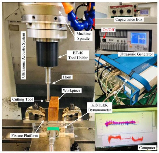
Figure 1.
The experimental configuration used for cutting the NHC core by RUM technology.
The ultrasonic machine tool (THU Ultrasonic 850) has key performance conditions summarized in Table 1. However, setting up the experimental procedure remains a lengthy and costly process. Thus, numerical modeling is a very interesting tool for simulating machining problems in various configurations, under different cutting conditions and at lower cost. For this purpose, a 3D numerical model of the milling process of NHC structures, using RUM technology, was developed by Abaqus Explicit software. In this paper, the NHC structure studied was composed of single walls and of double walls represented in the W and L directions, respectively, as shown in Figure 2a. The geometric dimensions of the hexagonal cell are described in Figure 2b [34].

Table 1.
Performance conditions of the THU Ultrasonic 850.
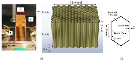
Figure 2.
(a) Geometric dimensions of the NHC core; (b) Geometric dimensions of the hexagonal cell.
According to the experimental procedure, the NHC core was machined using a specific cutting tool called UCK, which is a circular milling cutter made of ultrasonic high-speed steel (HSS-W18Cr4V) (Figure 3b). For this purpose, a cutting tool was designed respecting the geometric dimensions used in the experimental phase (see Figure 4) [34].
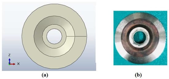
Figure 3.
Presentation of the UCK cutting tool used to cut the NHC core: (a) UCK designed by simulation; (b) UCK used in the experiment.
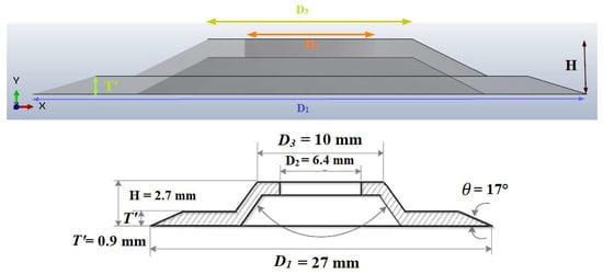
Figure 4.
Dimensions of the UCK cutting tool.
2.2. Setting Up of the Numerical Model
2.2.1. Presentation of the Numerical Model
The present work proposes a numerical study of the milling of an NHC structure using RUM technology, where the structure to be machined is composed of thin walls with low thickness (Figure 5a). In this regard, the walls of the NHC structure were meshed using four-node classic shell elements (S4R), with each node having six degrees of freedom (three translations and three rotations) with reduced integration. During the numerical simulation, the cutting tool was considered rigid, which means that it did not undergo any deformation throughout the machining operation. In order to represent it correctly in the numerical model, it was discretized using rigid quadrangular elements with 4 nodes (R3D4) commonly used for three-dimensional analysis (Figure 5b).
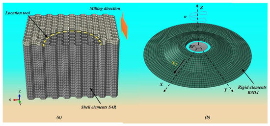
Figure 5.
(a) Mesh used in the FE model; (b) cutting conditions defined at reference point RP: n is the spindle speed and Vf is the feed rate.
Before the implementation of the numerical code, a main step was carried out to analyze the nonlinear parameters likely to influence the convergence of the numerical results. Several factors needed to be taken into account during numerical simulation, including the size mesh, the type of contact, and the friction coefficient. It should be noted that using a small mesh size can lead to a significant increase in computation time (CPU), especially in three-dimensional setups. Thus, to find the right compromise between the size of the mesh and the precision of the results, a mesh of around 0.4 mm was adopted, corresponding to a total number of elements of 83,649. During the milling simulation, general contact was used to model the interaction between the cutting tool and the walls of the NHC core. Due to the small thickness of the walls forming the NHC core, the contact between the cutting tool and the NHC structure was treated as a point contact, verified by Coulomb’s law. In this work, the value of the contact coefficient chosen for the numerical simulations was 0.1. In order to ensure full contact between the cutting tool and the NHC structure from the start of the simulation, an initial engagement was planned, taking into account the particulars geometries of the structure and the cutting tool, thus reducing the CPU calculation time (Figure 5a). In the numerical simulation, the boundary conditions were defined in accordance with the established experimental procedure (Figure 6b). In this context, the bottom surface of the NHC structure remained stationary, indicating that it was unable to move or rotate in any direction. For this purpose, in the numerical simulation, we applied total embedding to the lower surface of the NHC core, which had the effect of eliminating all translations (Ux = Uy = Uz = 0) along X, Y and Z and all rotations (URx = URy = URz = 0) around X, Y and Z (Figure 6a). Rotary ultrasonic machining (RUM) is a mechanical manufacturing process for material removal that relies on the coordination of three movements of the cutting tool: the feed motion along the OY axis, characterized by the feed rate Vf; the rotational motion around the OZ axis, characterized by a spindle speed n; and the vibratory motion along the OZ axis, applying a sinusoidal ultrasonic wave (Figure 6a). In order to follow the evolution of the machining precisely during the numerical simulation, a reference point, RP, was assigned on the axis of rotation of the cutting tool (Figure 5b). This reference point was essential for establishing cutting conditions and evaluating the cutting forces during the machining process. The UCK tool motion can be expressed in terms of global coordinates xyz by the following equations:
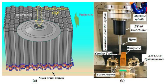
Figure 6.
Boundary conditions used in the numerical simulation: (a) used in the simulation; (b) used in the experience.
A represents ultrasonic vibration amplitude, is cutting speed, is feed rate, n is spindle speed, t is time and f is the vibration frequency which is 21.260 KHz in the present paper.
2.2.2. Law of Behavior and Criterion of Damage
The adoption of an appropriate and representative constitutive law remains essential in order to effectively simulate the chip formation process during machining. In this paper, the Nomex paper forming the NHC structure exhibited brittle elastic mechanical behavior, meaning that it reacted differently along the stress axes. This feature resulted in high tensile strength but relatively lower compressive strength [35,36]. In the context of the numerical modeling of NHC core machining, multiple layers were not included in the model, as their impact on this process was considered negligible. Indeed, the single-layer orthotropic approach is preferred for modeling due to its simplicity of implementation. The mathematical equations describing the stress–strain relationship of orthotropic material can be summarized as follows:
where σij and εij characterize the stress tensor and strain tensor, respectively. C designates the stiffness matrix, with i, j = 1, 2, 3,…, 6 [37].
The orthotropic mechanical properties of Nomex paper were determined from the study conducted by Kilchert and are presented concisely in Table 2 [38]. To evaluate the damage to the Nomex material, a Tsai–Wu failure criterion is used according the following equation: [39]:
where Fi and Fj represent the second- and fourth-order force tensors, respectively, defined as follows:
where X and Y represent the limiting stresses of the material in the longitudinal and transverse directions, respectively, while S denotes the limiting shear stress, as shown in Table 2.

Table 2.
The mechanical characteristics of Nomex paper.
When the failure criterion is reached, this means that a progressive damage process occurs, leading to the deterioration of the previously mentioned stiffness matrix.
The Tsai–Wu criterion constitutes a tool for assessing damage within each stressed element of a structure when it meets the conditions set out in Equation (6). This method allows you to determine if an element has suffered damage by comparing the stresses applied to the resistances of the material in different directions. To resolve the direction challenge and calculate the decrease in element stiffness, the Tsai–Wu criterion was decomposed into several stress components, according to Equation (8).
More precisely, once the Tsai–Wu failure criterion is reached, the Hk components will be calculated and compared to determine their maximum value. The highest Hk component is selected as the predominant damage mode, leading to a decrease in the stiffness of the associated elastic modulus and a deterioration in the corresponding properties, as shown in Table 3 [40,41].

Table 3.
Degradation of mechanical properties and corresponding variables according to the Tsai–Wu criterion.
In this analysis, the damage method used aims to decrease the stiffness of the individual elastic modules as soon as the breaking point is reached. For the Tsai–Wu criterion, the damage assessment is carried out based on several variables denoted as dk (with k ranging from 1 to 6), as illustrated by Equations (9) and (10). The formula describing the reduction in stiffness depends on the type of material and its mechanical behavior. For composite materials, the formula for stiffness reduction is calculated as follows [42]:
with m: softening parameter; e: Euler number; : deformation of rupture, which are determined as follows:
2.2.3. Cutting Force Calculation
During the experimental phase, the components of the cutting force (Fy, the feed component along Y, and Fx, the cutting component along X) are measured using the KISTLER-9256C2 dynamometer. This method makes it possible to calculate the average value in both directions, according to the following formulas:
Fx and Fy represent the averages of the components of the cutting force in the X and Y directions, while t1 and t2 represent, respectively, the start and end of the cutting process.
3. Results and Discussion
The deformation of the NHC core during the milling process can have significant consequences on the cutting force and the machined surface quality. The main cause of cell deformation is the low rigidity of the Nomex paper that forms the NHC core. However, the NHC structure has high rigidity in the direction of the thickness T along the z axis [43,44]. Therefore, the crushing component Fz has no significant influence on the machining process. This section of research focuses on three key aspects. Firstly, the influence of cutting conditions on the Fx and Fy components was carefully analyzed. In parallel, an in-depth evaluation of the impact of feed component Fy on the quality of the machined surface was carried out. Simultaneously, careful study focused on examining the influence of vibration amplitude on chip accumulation in front of the cutting tool.
3.1. Validation of the Numerical Model of the Cutting Simulation Assissted by Ultrasonic Vibration
3.1.1. Influence of the Feed Rate on the Cutting Force
In order to validate the numerical model of the milling of the NHC structure by RUM technology using the UCK cutting tool, numerical simulations were carried out according to the experimental protocol presented above. The aim of these simulations was to evaluate the influence of the feed rates such as 500 mm/min, 1000 mm/min, 1500 mm/min, 2000 mm/min, 2500 mm/min and 3000 mm/min on components Fx and Fy, in which the simulations were carried out both with and without the use of ultrasonic vibrations. The other cutting conditions were kept constant throughout the numerical modeling, such as the spindle speed at 5000 rpm, the vibration amplitude at 25 μm and the depth of cut at 2 mm. An in-depth comparison was carried out between the obtained results by the numerical model and those obtained by the experiment [34] (see Figure 7).
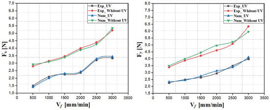
Figure 7.
Evolution of Fx and Fy according to the feed rates.
The obtained results show that components Fx and Fy increase as the feed rate of the cutting tool increases, both for the simulation and for the experiment, whether or not the ultrasonic vibrations are used. The increase in components Fx and Fy is mainly due to the increase in the amount of material removed per unit time. Furthermore, it is possible that the elastic deformation of the Nomex paper forming the NHC structure is responsible for this phenomenon by delaying the removal of the elements, leading to an accumulation of material in front of the tool and an overestimated resistance of the material, hence the increase in components Fx and Fy. When cutting the NHC structure using RUM technology, it is evident that the use of ultrasonic vibrations considerably reduces components Fx and Fy. In this context, the strong rotation and vibration of the cutting tool favorize the creation of cracks in the walls of the NHC structure, making it easier for the cutting tool to penetrate without resistance from the material forming the NHC structure. In contrast, when machining the NHC core without ultrasonic vibration, there is no vibration of the cutting tool, which is also reflected in the absence of crack propagation in the contact zone between the tool and the thin walls of the NHC structure, thus increasing components Fx and Fy. Additionally, when observing the process, it was noted that the feed force Fy was consistently greater than cutting component Fx. This results from the resistance of the material that builds up in front of the cutting tool during the milling process. On the other hand, the cutting force Fx in the OX cutting direction is quite low due to the specific characteristic of Nomex paper, which is considered fragile with a low density. The values of the obtained components Fx and Fy by the numerical simulation present a significant correspondence with the experimental results, demonstrating the robustness of the developed numerical model.
3.1.2. Influence of the Spindle Speed on the Cutting Force
This paragraph presents a series of rotary ultrasonic machining (RUM) simulations of the NHC core, in which the study was carried out both with and without the use of ultrasonic vibrations. The main objective was to evaluate the influence of different spindle speeds, such as 500 rpm, 1000 rpm, 2000 rpm, 3000 rpm, 4000 rpm and 5000 rpm, on components Fx and Fy generated by the cutting tool. It essential to note that the feed rate used to perform the numerical simulations was 500 mm/min, the vibration amplitude was 25 μm and the depth of cut was 2 mm. The numerical simulations were carried out for a duration of 0.24 s, which is equivalent to a cutting width of 2 mm. The results calculated by the FE model are compared with the experimental results and are presented in Figure 8 [34].
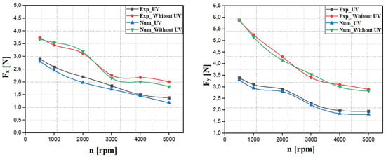
Figure 8.
Evolution of Fx and Fy according to the spindle speeds.
According to the results presented in Figure 8, a decrease in components Fx and Fy is observed with increasing spindle speed, both for the simulation and for the experiment, whether or not ultrasonic vibrations are used. As the spindle speed increases, the kinetic energy of the cutting tool increases significantly. This results in an increase in the material removal rate per unit time, which systematically leads to a decrease in the Fx and Fy components. On the contrary, at low spindle speeds, the cutting tool exerts insufficient pressure on the walls of the hexagonal structure, which can lead to the bending or deformation of the walls. Consequently, the inappropriate cutting of Nomex paper results in uncut fibers, weakening the overall structure of the material and thus hindering the efficient evacuation of the formed chips. These chips can accumulate around the cutting zone, causing local overloading of the tool and the disruption of the cutting process, thus increasing the components of the cutting force in the X and Y directions. Furthermore, for all spindle speeds examined, feed component Fy is higher than cutting component Fx. This is due to the accumulation of chips in front of the cutting tool UCK, generating additional force in the direction of advance and thus causing an increase in the advance component Fy. On the other hand, the fragility of Nomex paper can lead to less resistance of the cutting tool in the cutting direction X, resulting in relatively low values of component Fx. Generally, the application of ultrasonic vibrations during the milling process results in a significant reduction in the Fx and Fy components compared to conventional cutting, thereby helping to prevent premature wear of the cutting tool. By comparing the presented results, a satisfactory correlation was observed between the components of the cutting force calculated by the numerical model and those resulting from the experiment, thus demonstrating the reliability of the developed numerical model.
3.1.3. Influence of the Vibration Amplitude on the Cutting Force
As part of this study, numerical simulations were carried out to examine the impact of the vibration amplitude of the cutting tool on the Fx and Fy components using RUM technology. This research was carried out by changing the vibration amplitudes of the cutting tool, namely to 5 µm, 10 µm, 15 µm, 25 µm and 27 µm. Meanwhile, the machining parameters, such as feed rate of 500 mm/min, spindle speed of 3000 rpm and cutting depth of 2 mm, were kept constant throughout the machining process. It should be noted that the numerical simulations were carried out for a period of 0.36 s, corresponding to a cutting width of 3 mm. The results obtained by the numerical model are compared with the experimental results and are presented in Figure 9.
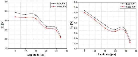
Figure 9.
Evolution of Fx and Fy according to the vibration amplitudes.
According to the results shown in Figure 9, there is a decrease in components Fx and Fy as a function of increasing vibration amplitude. The reduction in the Fx component is explained by the creation of incisions resulting from the rotation and vibration of the cutting tool. This action promotes the propagation of cracks in the phenolic resin, which facilitates the penetration of the cutting tool into the walls of the NHC structure. For vibration amplitudes between 5 µm and 10 µm, a slight decrease in the Fy component is noted. In fact, when the tool vibrates slightly, this reduces the impact on the part, thus limiting the propagation of cracks. In this case, the space between the cutting tool and the walls of the NHC structure is very small, resulting in closer contact between the two. As a result, friction during the cutting process increases, resulting in a higher cutting force. By increasing the values of the vibration amplitude, a clear decrease in power supply component Fy is observed. In this case, the contact between the cutting tool and the walls of the NHC structure becomes less significant, which leads to a reduction in the force generated. In general, a correlation between the simulation and the experiment is clearly observed, thus demonstrating the reliability of the numerical model developed.
3.2. Analysis of Machined Surface Quality
The quality of the machined surface of NHC cores plays a crucial role in the construction of Nomex honeycomb sandwich composite structures. Therefore, optimizing the surface quality of this type of structure is essential to prevent delamination between the core and the skins that form the sandwich structure. According to experimental results, the most common machining defects in NHC core milling are burrs and tears to fibers. Therefore, optimizing the cutting tool edge is of paramount importance in the machining process. In order to validate the numerical model of the milling of the NHC structure, numerical simulations were carried out to highlight the influence of component Fy on the quality of the machined surface. These simulations were carried out while strictly respecting the previously established cutting conditions for two ranges of the values of Fy: Fy ≤ 3N and Fy > 3N. During the experimental phase, the machined surface quality defects were revealed using an optical microscope (model 55XA, SOIF, Shanghai, China) [34]. However, the machining defects resulting from the numerical model were identified on the basis of visual examination with the naked eye. Figure 10 and Figure 11 present the machined surfaces obtained by the numerical model and the experiment.
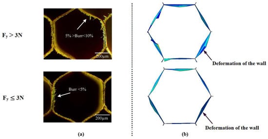
Figure 10.
Surface quality resulting from RUM technology with UV: (a) Surface quality resulting from the numerical model; (b) surface quality resulting from the experiment.
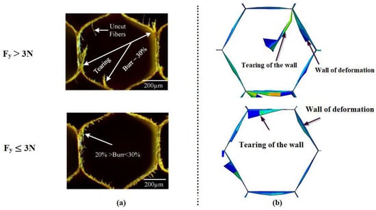
Figure 11.
Surface quality resulting from RUM technology without UV: (a) Surface quality resulting from the numerical model; (b) surface quality resulting from the experiment.
The main observation is that machining defects are closely linked to the value of feed component Fy, whether with UV or without. The results of the experiment have shown that the main machining defects observed on the NHC core are burrs and tears to uncut fiber [34]. On the other hand, the machining defects revealed by the numerical simulation are deformation and tears to the walls. It should be noted that the experimental tests did not take into account the potential deformation of the walls during the machining process. Furthermore, burrs, which manifest themselves as excess material on the cell walls, could not be detected by the numerical model, as they were represented by S4R shell elements without thickness. In general, it was observed that the tears and deformations of the walls were more pronounced for the high values of the advance force Fy 3N in both tested cases, whether with or without UV. In fact, the high values of Fy were obtained thanks to the low spindle speed of the cutting tool, thus causing the elastic deformation of the thin walls until they tore. For the low spindle speed, the cutting tool does not apply sufficient pressure to the walls of the hexagonal structure, which can cause elastic deformation or lead to their folding. As a result, some fibers in Nomex paper may remain intact, creating uncut fibers that compromise the overall strength of the structure and cause deterioration in the quality of the machined surface. On the other hand, the numerical and experimental studies have clearly demonstrated the benefits of ultrasonic vibrations during the cutting process. These vibrations reduce contact between the tool cutting edge and the thin walls of the NHC structure, which reduces friction and improves heat dissipation during cutting. As a result, the cutting tool can penetrate the walls of the NHC structure more easily, thereby reducing machining defects and improving the quality of the machined surface. By analyzing the results of the numerical and comparing them with those obtained by the experiment, we found a strong correlation between the simulation and experiment, which reinforces the confidence of the numerical model developed.
3.3. Analysis of Chip Distribution in Front of the Cutting Tool
The accumulation of chips in front of the cutting tool represents a technical challenge for engineers and researchers in certain fields, particularly machining and manufacturing. Chip accumulation in front of the cutting tool can cause various problems. It disrupts the cutting movement, generating unwanted vibrations likely to deteriorate the quality of the surface and accelerate the wear of the cutting tool. As part of this study, numerical simulations were carried out in order to highlight the influence of the vibration amplitude on the accumulation of the chips in front of the cutting tool. For this purpose, three amplitudes were tested: 5 µm, 15 µm and 27 µm. The numerical simulations were performed using the same cutting conditions, including a spindle speed of 5000 rpm and a feed rate of 3000 mm/min. The duration of each simulation was 0.06 s, which corresponded to a cutting width of the 3 mm. The obtained results are shown in Figure 12, Figure 13 and Figure 14.
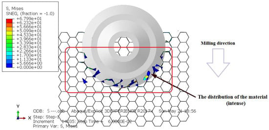
Figure 12.
Accumulation of the chips in the front of the UCK cutting tool, for A = 5 µm.
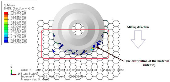
Figure 13.
Accumulation of the chips in the front of the UCK cutting tool, for A = 15 µm.
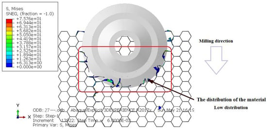
Figure 14.
Accumulation of the chips in the front of the UCK cutting tool, for A = 27 µm.
The obtained results show that the amplitude of ultrasonic vibrations directly influences the accumulation of chips in front of the cutting tool. In this context, it is obvious that high amplitudes significantly reduce the accumulation of chips in front of the cutting tool. For low amplitudes, the contact between the edge of the tool and the walls of the structure becomes very significant. In this case, the cutting tool does not easily penetrate the material, creating short-length cracks on the walls of the NHC structure. Thus, the poor cutting of the walls of the NHC structure promotes their elastic deformation and leads to the accumulation of chips in front of the cutting tool. By increasing the amplitude of ultrasonic vibrations beyond 5 µm, a notable reduction in chip accumulation in front of the cutting tool is observed. In this case, the high amplitudes of vibrations and the high rotation speed reduce the contact between the edge of the cutting tool and the walls of the NHC structure, which facilitates the penetration of the cutting tool into the thin wall, consequently intensifying the propagation of cracks. Thus, the walls of the structure are cut optimally, which favors the formation of small chips and reduces their accumulation in front of the cutting tool. However, it should be noted that chip accumulation persists for all amplitudes examined. This can be attributed to the mechanical behavior of Nomex paper, which is considered elastic in this model. In this regard, the elastic deformation of Nomex paper delays the removal of elements, which causes an accumulation of material in front of the cutting tool forces and an overestimation of the material’s strength. By analyzing the obtained results, we noticed that the conclusions drawn from the simulation provided a coherent explanation of everything we had discussed previously. As a result, the numerical model developed is represented as a numerical platform capable of handling all special cases.
4. Conclusions
In this work, a three-dimensional numerical model was developed to analyze the machining process of NHC structures using RUM technology both with and without the use of ultrasonic vibrations. This model has been rigorously validated by experimental tests comparing the Fx and Fy components, as well as the quality of the machined surface, under different cutting conditions. Furthermore, the numerical model offers the possibility of evaluating the influence of the amplitude of ultrasonic vibrations on the accumulation of chips in front of the cutting tool. The results of the study led to the following conclusions:
- The influence of the feed rate on components Fx and Fy was carefully examined; it was observed that these components increase with the increase in the feed rate, both for the simulation and just for the experiment. Furthermore, the results indicate that the use of ultrasonic vibrations helps minimize the negative effects of components Fx and Fy for both directions. In the end, concrete agreement is observed between the obtained results by the numerical model and the results determined by the experiment.
- The analysis of components Fx and Fy as a function of the spindle speed reveals similarities between the orthotropic elastic behavior and that of composite materials. The significant reduction in components Fx and Fy with high spindle speeds is observed for the two cases tested, whether with or without UV. Interestingly, the simulation based on the orthotropic behavior with the Tsai–Wu failure criterion follows a similar trend as the experimental results.
- By analyzing the influence of feed component Fy on the quality of the machined surface, it becomes clear that this relationship is firmly established. The combination between ultrasonic vibrations and the reduction in feed component Fy demonstrates a significant improvement in the quality of the machined surface. A significant correlation is noted in the obtained results by the numerical model and those obtained by the experiment, which confirms the credibility of the proposed numerical model.
- The developed numerical model makes it possible to study the influence of vibration amplitude on components Fx and Fy. The obtained results clearly indicate that higher vibration amplitudes result in a significant reduction in these components, thus helping to avoid premature wear of the cutting tool. In the end, concrete agreement is noted between the obtained results by the numerical model and those determined by the experiment.
- The numerical model shows that feed component Fy prevails over Fx, due to the accumulation of material in front of the cutting tool and the low density of the Nomex paper constituting the NHC structure.
- The numerical model makes it possible to analyze the influence of vibration amplitude on chip accumulation in front of the cutting tool. The higher amplitudes appear to help reduce unwanted chip buildup, helping to improve machining efficiency, optimize machined surface quality and prevent premature chip wear of the cutting tool.
- The numerical model allows the analysis of complex machining simulations, which are difficult to perform experimentally. It thus offers researchers and engineers the possibility of improving cutting performance while avoiding costly experimental studies.
Author Contributions
Analysis, data and results interpretation, manuscript writing, methodology and investigation: T.Z.; supervision, methodology, investigation, analysis, data and results interpretation: M.N.; manuscript writing: J.-E.S.; analysis, manuscript writing: A.B. All authors have read and agreed to the published version of the manuscript.
Funding
This research received no external funding.
Data Availability Statement
Data are contained within the article.
Conflicts of Interest
The authors declare no conflicts of interest.
References
- Haq, S.U.; Raju, G.G. DC breakdown characteristics of high temperature polymer films. IEEE Trans. Dielectr. Electr. Insul. 2006, 13, 917. [Google Scholar] [CrossRef]
- Yang, C.Q.; He, Q.; Lyon, R.E.; Hu, Y. Investigation of the flammability of different textile fabrics using micro scale combustion calorimetry. Polym. Degrad. Stab. 2010, 95, 108–115. [Google Scholar] [CrossRef]
- Foo, C.C.; Chai, G.B.; Seah, L.K. Mechanical properties of Nomex material and Nomex honeycomb structure. Compos. Struct. 2007, 80, 588–594. [Google Scholar] [CrossRef]
- Castanie, B.; Bouvet, C.; Ginot, M. Review of composite sandwich structure in aeronautic applications. Compos. Part C Open Access 2020, 1, 100004. [Google Scholar] [CrossRef]
- Botelho, E.C.; Silva, R.A.; Pardini, L.C.; Rezende, M.C. A review on the development and properties of continuous fiber/epoxy/aluminum hybrid composites for aircraft structures. Mater. Res. 2006, 9, 247–256. [Google Scholar] [CrossRef]
- Xu, J.; Wang, C.; Feng, P.; Jiang, E.; Feng, F. Meso-scale cracks initiation of Nomex honeycomb composites in orthogonal cutting with a straight blade cutter. Compos. Sci. Technol. 2023, 223, 109914. [Google Scholar] [CrossRef]
- Hu, X.P.; Chen, S.Y.; Zhang, Z.C. Research on curved surface forming of nomex honeycomb material based on ultrasonic NC cutting. Adv. Mater. Res. 2012, 538, 1377–1381. [Google Scholar] [CrossRef]
- Zarrouk, T.; Salhi, J.E.; Atlati, S.; Nouari, M.; Salhi, M.; Salhi, N. Modeling and numerical simulation of the chip formation process when machining Nomex. Environ. Sci. Pollut. Res. 2022, 29, 98–105. [Google Scholar] [CrossRef]
- Zarrouk, T.; Salhi, J.E.; Nouari, M.; Salhi, M.; Atlati, S.; Salhi, N. Analysis of friction and cutting parameters when milling honeycomb composite structures. Adv. Mech. Eng. 2021, 13, 16878140211034841. [Google Scholar] [CrossRef]
- Zarrouk, T.; Nouari, M.; Makich, H. Simulated Study of the Machinability of the Nomex Honeycomb Structure. J. Manuf. Mater. Process. 2023, 7, 28. [Google Scholar] [CrossRef]
- Li, Z.; Yuan, S.; Ma, J.; Shen, J.; Batako, A.D. Study on the surface formation mechanism in scratching test with different ultrasonic vibration forms. J. Mater. Process. Technol. 2021, 294, 117108. [Google Scholar] [CrossRef]
- Yang, Z.; Zhu, L.; Zhang, G.; Ni, C.; Lin, B. Review of ultrasonic vibration-assisted machining in advanced materials. Int. J. Mach. Tools Manuf. 2020, 156, 103594. [Google Scholar] [CrossRef]
- Jain, A.K.; Pandey, P.M. Modeling of un-deformed chip thickness in RUM process and study of size effects in μ-RUM. Ultrasonics 2017, 77, 1–16. [Google Scholar] [CrossRef] [PubMed]
- Sun, L.; Liao, W.; Zheng, K.; Tian, W.; Liu, J.; Feng, J. Stability analysis of robotic longitudinal-torsional composite ultrasonic milling. Chin. J. Aeronaut. 2022, 35, 249–264. [Google Scholar] [CrossRef]
- Liu, J.; Jiang, X.; Han, X.; Zhang, D. Influence of parameter matching on performance of high-speed rotary ultrasonic elliptical vibration-assisted machining for side milling of titanium alloys. Int. J. Adv. Fab. Technol. 2019, 101, 1333–1348. [Google Scholar] [CrossRef]
- Zhang, M.; Zhang, D.; Geng, D.; Shao, Z.; Liu, Y.; Jiang, X. Effects of tool vibration on surface integrity in rotary ultrasonic elliptical end milling of Ti–6Al–4V. J. Alloys Compd. 2020, 821, 153266. [Google Scholar] [CrossRef]
- Wang, J.; Zhang, J.; Feng, P.; Guo, P. Damage formation and suppression in rotary ultrasonic machining of hard and brittle materials: A critical review. Céram. Int. 2018, 44, 1227–1239. [Google Scholar] [CrossRef]
- Wang, J.; Feng, P.; Zhang, J. Reducing edge chipping defect in rotary ultrasonic machining of optical glass by compound step-taper tool. J. Manuf. Processus 2018, 32, 213–221. [Google Scholar] [CrossRef]
- Zha, H.; Feng, P.; Zhang, J.; Yu, D.; Wu, Z. Material removal mechanism in rotary ultrasonic machining of high-volume fraction SiCp/Al composites. Int. J. Adv. Fab. Technol. 2018, 97, 2099–2109. [Google Scholar] [CrossRef]
- Dong, S.; Liao, W.; Zheng, K.; Liu, J.; Feng, J. Investigation on exit burr in robotic rotary ultrasonic drilling of CFRP/aluminum stacks. Int. J. Mech. Sci. 2019, 151, 868–876. [Google Scholar] [CrossRef]
- An, Q.; Dang, J.; Ming, W.; Qiu, K.; Chen, M. Experimental and Numerical Studies on Defect Characteristics During Milling of Aluminum Honeycomb Core. J. Manuf. Sci. Eng. 2019, 141, 031006. [Google Scholar] [CrossRef]
- Abbadi, A.; Tixier, C.; Gilgert, J.; Azari, A. Experimental study on the fatigue behaviour of honeycomb sandwich panels with artificial defects. Compos. Struct. 2015, 120, 394–405. [Google Scholar] [CrossRef]
- Meruane, V.; del Fierro, V. An inverse parallel genetic algorithm for the identification of skin/core debonding in honeycomb aluminium panels. Struct. Control Health Monit. 2015, 22, 1426–1439. [Google Scholar] [CrossRef]
- Wang, J.; Feng, P.; Zhang, J.; Guo, P. Experimental study on vibration stability in rotary ultrasonic machining of ceramic matrix composites: Cutting force variation at hole entrance. Ceram. Int. 2018, 44, 14386–14392. [Google Scholar] [CrossRef]
- Wang, H.; Cong, W.; Ning, F.; Hu, Y. A study on the effects of machining variables in surface grinding of CFRP composites using rotary ultrasonic machining. Int. J. Adv. Manuf. Technol. 2018, 95, 3651–3663. [Google Scholar] [CrossRef]
- Yuan, S.; Li, Z.; Zhang, C.; Guskov, A. Research into the transition of material removal mechanism for C/SiC in rotary ultrasonic face machining. Int. J. Adv. Manuf. Technol. 2018, 95, 1751–1761. [Google Scholar] [CrossRef]
- Chen, X.; Wang, H.; Hu, Y.; Zhang, D.; Cong, W.; Burks, A.R. Rotary ultrasonic machining of CFRP compo-sites: Effects of machining variables on workpiece delamination. In International Manufacturing Science and Engineering Conference. Am. Soc. Mech. Eng. 2019, 58752, V002T03A051. [Google Scholar] [CrossRef]
- Li, C.; Piao, Y.; Meng, B.; Hu, Y.; Li, L.; Zhang, F. Phase transition and plastic deformation mechanisms induced by self-rotating grinding of GaN single crystals. Int. J. Mach. Tools Manuf. 2022, 172, 103827. [Google Scholar] [CrossRef]
- Sandá, A.; Sanz, C. Rotary ultrasonic machining of ZrO2-NbC and ZrO2-WC ceramics. Int. J. Mach. Mach. Mater. 2020, 22, 165–179. [Google Scholar] [CrossRef]
- Abdo, B.M.A.; El-Tamimi, A.; Alkhalefah, H. Parametric Analysis and Optimization of Rotary Ultrasonic Machining of Zirconia (ZrO2) Ceramics. IOP Conf. Ser. Mater. Sci. Eng. 2020, 727, 012009. [Google Scholar] [CrossRef]
- Xia, Y.; Zhang, J.; Wu, Z.; Feng, P.; Yu, D. Study on the design of cutting disc in ultrasonicassisted machining of honeycomb composites. IOP Conf. Ser. Mater. Sci. Eng 2019, 611, 012032. [Google Scholar] [CrossRef]
- Sun, J.; Dong, Z.; Wang, X.; Wang, Y.; Qin, Y.; Kang, R. Simulation and experimental study of ultrasonic cutting for aluminum honeycomb by disc cutter. Ultrasonics 2020, 103, 106102. [Google Scholar] [CrossRef] [PubMed]
- Ahmad, S.; Zhang, J.; Feng, P.; Yu, D.; Wu, Z.; Ke, M. Research on design and FE simulations of novel ultrasonic circular saw blade (UCSB) cutting tools for rotary ultrasonic machining of nomex honeycomb composites. In Proceedings of the 2019 16th International Bhurban Conference on Applied Sciences and Technology (IBCAST), Islamabad, Pakistan, 8–12 January 2019; pp. 113–119. [Google Scholar] [CrossRef]
- Ahmad, S.; Zhang, J.; Feng, P.; Yu, D.; Wu, Z. Experimental study on rotary ultrasonic machining (RUM) characteristics of Nomex honeycomb composites (NHCs) by circular knife cutting tools. J. Manuf. Process. 2020, 58, 524–535. [Google Scholar] [CrossRef]
- Chung, J.; Waas, A.M. Compressive Response of Honeycombs Under In-Plane Uniaxial Static and Dynamic Loading, Part 1: Experiments. AIAA J. 2002, 40, 966–973. [Google Scholar] [CrossRef]
- Goldsmith, W.; Louie, D.L. Axial perforation of aluminum honeycombs by projectiles. Int. J. Solids Struct. 1995, 32, 1017–1046. [Google Scholar] [CrossRef]
- Jaafar, M. Étude Expérimentale et Simulation Numérique de L’usinage des Matériaux en nids d’abeilles: Application au Fraisage des Structures Nomex® et Aluminium. Ph.D. Thesis, Université de Lorraine, Nancy, France, 2018. ⟨NNT: 2018LORR0303⟩. [Google Scholar]
- Kilchert, S. Nonlinear Finite Element Modelling of Degradation and Failure in Folded Core Composite Sandwich Structures. Ph.D. Thesis, Faculty of Aerospace Engineering and Geodesy of the Universität Stuttgart, Stuttgart, Germany, 2013. [Google Scholar] [CrossRef]
- Heimbs, S. Sandwichstrukturen mit Wabenkern: Experimentelle und Numerische Analyse des Schädigungsverhaltens unter Statischer und Kurzzeitdynamischer Belastung; Institut für Verbundwerkstoffe GmbH: Kaiserslautern, Germany, 2008. [Google Scholar]
- Liu, P.F.; Zheng, J.Y. Progressive failure analysis of carbon fiber/epoxy composite laminates using continuum damage mechanics. Mater. Sci. Eng. A 2008, 485, 711–717. [Google Scholar] [CrossRef]
- Padhi, G.S.; Shenoi, R.A.; Moy, S.S.J.; Hawkins, G.L. Progressive failure and ultimate collapse of laminated composite plates in bending. Compos. Struct. 1997, 40, 277–291. [Google Scholar] [CrossRef]
- Gemkow, K.S.; Vignjevic, R. Strain-softening in continuum damage models: Investigation of MAT-058. In Proceedings of the 9th European LS-DYNA Conference, Manchester, UK, 2–4 June 2013. [Google Scholar]
- Kim, D.S.; Lee, J.R. Compressive Mechanical Properties of the Nomex/Thermoset Honeycomb Cores. Polym. Adv. Technol. 1997, 8, 1–7. [Google Scholar] [CrossRef]
- Lamb, A.J.; Pickett, A.K.; Chaudoye, F. Experimental characterisation and numerical modelling of hexagonal honeycomb cellular solids under multi-axial loading. Strain 2011, 47, 2–20. [Google Scholar] [CrossRef]
Disclaimer/Publisher’s Note: The statements, opinions and data contained in all publications are solely those of the individual author(s) and contributor(s) and not of MDPI and/or the editor(s). MDPI and/or the editor(s) disclaim responsibility for any injury to people or property resulting from any ideas, methods, instructions or products referred to in the content. |
© 2024 by the authors. Licensee MDPI, Basel, Switzerland. This article is an open access article distributed under the terms and conditions of the Creative Commons Attribution (CC BY) license (https://creativecommons.org/licenses/by/4.0/).
