Abstract
Manual counting and packaging processes often involve repetitive, error-prone tasks. Specifically, packaging wooden handles, utilized in gardening tools and cutlery, typically relies on labor-intensive methods with dimensions varying in diameter, length and mass. These variations complicate packaging, requiring precise counting and diverse handling solutions. This article introduces an automated counting structure tailored for a wide array of wooden handles manufactured by a company in northern Portugal. Employing standardized mechanical design methodologies, we delineate crucial stages encompassing the design, development, implementation and testing of this specialized counting equipment. The machine has been partially integrated into the management system of the company, taking into account future global integration according to the Industry 4.0 concept.
1. Introduction
Packaging plays a vital role in safeguarding a wide array of products, from food items like sugar and rice packaged in bags to cereals in boxes and beverages in bottles. Its primary objective is to protect products during handling and influence consumer choice [1,2,3,4,5].
Automated packaging involves methodically depositing products into suitable containers. While methods based on quantity, weight or time are common, processes reliant on weight may exhibit variations in the final quantity due to diverse product dimensions and masses, as observed in screw packaging [5]. Wooden handles, essential tool components, come in varying configurations, diameters, and lengths to ensure optimal grip and handling. Wood’s anisotropy, coupled with factors like humidity and density, affects handle quality and weight, thereby impacting the packaging process [6].
This paper addresses the challenge of counting and packaging wooden handles, considering their structural complexities and raw material influences. The subsequent sections will discuss the methods and materials used in system development, steps involved in constructing the packaging system, results analysis, conclusions, and future study directions.
Wooden handles play a crucial role in facilitating tool handling by providing optimal grip and contact between the human hand and the tool. Their diverse configurations are pivotal in achieving this, often incorporating features such as grooves to increase friction. Figure 1 illustrates various handle configurations [6].
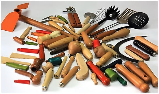
Figure 1.
Different configurations of wooden handles [6].
The manual counting process, depicted in Figure 2, showcases the current manual packaging method used for wooden handles. This intricate procedure demands operators to simultaneously support the packaging (bag) while counting the handles to be packaged. The labor-intensive nature of this process often leads to errors, inefficiencies, and time wastage, necessitating a more efficient and accurate solution.
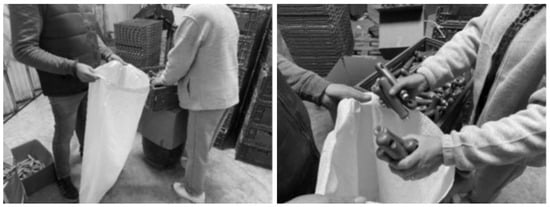
Figure 2.
Packaging process for wooden handles [7].
The complexity involved in packaging wooden handles necessitates a comprehensive approach that integrates robust methods and appropriate materials. Section 2 delineates systematic strategies and materials used in developing the automated packaging system. This section expounds upon the systematic progression from ideation to execution in crafting a reliable packaging solution for wooden handles, considering the intricacies observed in various packaging processes. The subsequent sections delve into the methods, materials utilized, development steps and results analysis of the automated packaging system.
This document is structured as follows: This section introduces the challenge of counting wood products and mentions some of the problems associated with their processing. Section 2 discusses the methods and materials used to develop the system, while Section 3 describes the main steps taken to develop and build the packaging system. Section 4 presents some results and analyzes the behavior of the equipment. Section 5 finishes with conclusions and future work.
2. Materials and Methods
2.1. Characterization of Best-Selling Products
The study commenced by characterizing the best-selling wooden handles by their shape, diameter, and length. A comprehensive analysis was undertaken to discern the crucial variables, particularly length and diameter, to understand their interrelation, as illustrated in Table 1 [7].

Table 1.
Sales analysis for 2022—diameter–length ratio [7].
The analysis of Table 1 elucidates that nearly 95% of the sales in 2022 were dominated by handles ranging between 100 and 150 mm in length. Notably, within this length range, approximately 90% of the handles sold had diameters ranging from 25 to 35 mm. This statistical benchmark was pivotal in formulating the handle counting solution.
2.2. Evaluation of Current Packaging Process
A SWOT analysis was conducted on the existing packaging process to devise specialized equipment for packaging handles of varied dimensions. The analysis revealed several pros and cons. The pros of manual packaging encompassed the processing speed for small quantities and the absence of specific equipment, albeit with quality control limited to a visual level. Conversely, cons included a slow processing time for large batches, necessitating several employees, error potential due to fatigue, ergonomic challenges, repetitive movements leading to injuries and high physical effort, as depicted in Figure 2. The challenges outweighed the benefits, prompting the need to develop automated equipment.
2.3. Weighing the Wooden Handles
Weighing wooden handle packages necessitates adaptable systems capable of accommodating diverse configurations [8]. Conventional packaging systems cater to homogenous products with defined structures and densities. However, flexible solutions catering to wood’s anisotropic nature are intricate due to differences in density and moisture content [9,10]. An experiment was conducted by weighing 600 handles as a reference, validating that their reference mass approximated 27 kg, Figure 3. Subsequent weighing of additional handle batches reaffirmed consistency in mass, dispelling doubts regarding the influence of density and humidity.
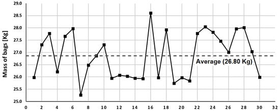
Figure 3.
Quantity mass ratio per bag of 600 units.
A larger-scale experiment involved evaluating the weight variation across 30 bags, each containing 600 units. The graph depicted a significant dispersion in values, averaging around 26.80 kg per bag, indicating a difference in humidity and density between woods. Density and moisture measurements from 7 samples further confirmed variations in mass, with an average density of 0.7448 g/cm3 and an average humidity of 13.39%.
Despite a smaller sample size for density and moisture measurement, it substantiated the influence of these parameters on the final package mass.
Section 2 illuminates the challenges encountered in traditional handle counting methodologies. Moving forward, Section 3 delves into the innovative approach undertaken to address these limitations, focusing on the development of an automated piece-by-piece counting system. This section outlines the methodologies adopted, the structural design considerations and the mechanical project evolution leading to the revolutionary packaging equipment.
3. Packing Machine
Counting based on weight turned out to be an inadequate solution for this type of problem due to the impossibility of obtaining an exact number of handles per bag. Counting errors result in losses for both the company and the customer. Therefore, the most suitable method for this problem would be piece-by-piece counting, i.e., transitioning from the current counting process to an automated system. Thus, this section presents the steps that guided the development of the packaging system, starting with the design concepts and methodologies used in its development.
3.1. Methodology
Design for Excellence (DFX) is a concept that allows results to be obtained that are as close as possible to excellence in an engineering project. It takes a systematic approach to design, focusing on all aspects of the product, from idea conception to final delivery, providing best practices and guidelines to ensure correct manufacturing in its early production phase [11].
The DFX concept is design focused (75%) with manufacturing in the background (25%). This inversion of traditional concepts allows for detailing the project, avoiding errors that will later lead to delays in development [11,12]. Additionally, it considers many of the crucial aspects of development in the design phase, contemplating areas dedicated to manufacturing, sustainability, costs, reliability, maintenance, quality, and tests, among others [12].
The VDI 2206 standard proposes a multidisciplinary development methodology for mechatronic systems. This methodology uses the V-model (Figure 4) as a reference, based on the description of the requirements, the first phase of the project, which culminates in the creation of a multidisciplinary solution, divided into subfunctions, with a view to finding solutions whose action is divided into the various domains [13]. All results are integrated to obtain an overall system solution. In an intermediate phase, a verification of the properties of the system under development is carried out, with the initial requirements, continuously and throughout the entire project, until the final product is obtained.
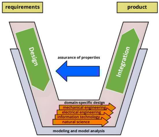
Figure 4.
V-model on the macro-level in VDI 2206. Adapted from [13].
3.2. Mechanical Project
The development of equipment must be focused on its ability to perform the function for which it is designed. As such, there is a need to develop a set of studies aimed at obtaining the best solution to the problem, which conceptually can be achieved by complying with the requirements defined by the VDI 2221 standard [14]. Then, and according to the standardization presented and for the equipment produced to meet all the pre-established requirements, several stages were defined with the aim of clarifying the final objectives, which are as follows:
- (a)
- Clarification and establishment of project objectives;
- (b)
- Establishing the product function structure;
- (c)
- Establishing the product specifications;
- (d)
- Creation of alternative solutions;
- (e)
- Evaluating the alternative solutions;
- (f)
- Perfecting the details.
The adoption of these methodologies was aimed at eliminating disagreements between the final solution and the initially defined objectives, so the implementation of a tree diagram (Figure 5) was an essential tool in defining the objectives to be achieved.
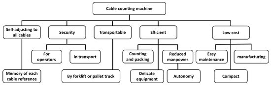
Figure 5.
Project tree.
Analyzing the tree diagram, a series of inputs and outputs were defined, portraying the essential functions of the system [15]. Thus, in addition to the traditional inputs and outputs of the system like energy, material, and signal [15], the following subfunctions were identified as essential:
- (a)
- Organization of handles;
- (b)
- Pass one-to-one;
- (c)
- Counting and packing, which made the mechanical project transparent.
On the other hand, morphologically, the mechanical design consists of a series of combinations of elements capable of producing a final solution that, in most situations, involves already-existing solutions [14]. In this case, the solution for the packaging equipment assumed a final configuration consisting essentially of a vibratory feeding system, a set of sensors and an automatic packaging system, resulting from the morphological analysis shown in Table 2.
Table 2.
Morphological map of the automatic handle counting system [7].
Structural Design
The structural design of the equipment (solution resulting from the combination shown in Table 2) translates into the fundamental stage of equipment construction. For this, it is necessary to define its dimensions considering, initially, the dimensions of the packaging bags. Based on this parameter, it was imposed, in terms of the quality of the packaged products, that vertical packages could not have at any stage of the process a drop height greater than 500 mm. In this sense, it was necessary to ensure that the defined drop height was maintained, regardless of the number of packed handles; that is, it was necessary to create a mobile platform that dynamically adjusts itself depending on the level sensor control signal, shown in Figure 6.
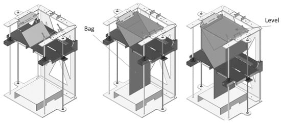
Figure 6.
Dynamic adjustment of the packaging system.
The movement of ascent and descent of the platform is carried out by two trapezoidal spindles placed at the ends. In the advanced position, two horizontal level plates are placed, delimiting the number of handles received, which varies from configuration to configuration. In the lowest position of the packaging process, the plates move back allowing complete filling of the bag.
3.3. Dynamic Analysis of the System
The dimensional parameters of the project are fundamental factors for the correct functioning of the packaging system. These factors are directly related to the masses to be moved, operating times, working speeds and other features that in some way can influence the behavior of the system. The handle level platform and component mass values are shown in Figure 7.
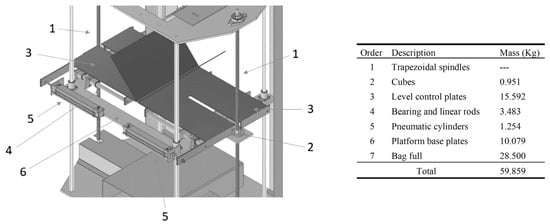
Figure 7.
Level platform details.
Since the handle level platform is the fundamental component of the system, its study assumed the main role both in terms of working speeds and the torques necessary for its movement. Therefore, the times of descent and ascent of the platform were dictated by the rotation induced in the spindles and by their pitch. In this case, it was considered that the downward movement was slow and it was defined experimentally depending on each configuration and the dimensions of the handles to be packaged, while the upward movement was considered fast, depending only on the rotation speed of the engine, the relationship between pulleys and the total mass transported vertically (≈60 kg, see Figure 7).
The ascent and descent of the platform are carried out by two trapezoidal spindles conditioned by the associated speeds. Therefore, the factors that determine the choice of the pitch of a spindle are the times of rise of the platform and the speed of rotation induced by them, as well as the distance to travel. Thus, the displacement or feed per revolution is related to the helix angle which can be described by
where λ is the helix angle in degrees [°], l is the lead of the screw [mm] and dm is the mean diameter of the screw [mm]. The average diameter corresponds to the point of contact between the spindle and hub cubes. It should be noted that the upward force depends not only on the external force but on all forces associated with the point of contact of the bodies. Thus, if we consider a free-body diagram applied at the point of contact, we will have to consider not only the external force but also the upward force, the normal reaction force, the frictional force and the force that forces the cube to descend.
From the balance of forces in x and y and solving the system as a function of the ascent force, we will obtain the expression that translates into the driving force to be applied to the spindle in the ascent. The value of the upward driving force is given by
where Fs is the upward force [N], µ is the coefficient of friction and F is the external force [kN]. Considering (1) and dividing (2) by cos λ (recalling that cos α = 1⁄secα), we obtain the expression that represents the driving force applied to the spindle in case the cube goes up.
where the fillet angle equals 2α, while in the metric system 2α equals 30°.
The moment that must be applied to the spindle to raise the cube is given by
which is nothing more than the moment to apply to the spindles to raise the platform to handle level and overcome the friction of the threads.
Proceeding in a similar way to the dynamic analysis of the cube’s upward movement, in relation to its downward movement, the following expressions result:
From the spindle dynamic analysis point of view, one must also consider whether (6) assumes negative values, cubes descent without the need to apply any moment or whether it assumes positive values, a self-immobilized system. Thus, the necessary condition for self-immobilization will be given by
3.3.1. Spindle Selection
The factors that determined the choice of the spindle pitch were the platform rise times and the rotation speed induced by them. It was defined that the handle level control platform should travel 720 mm, bag height, in a maximum rise time of 8 s.
Based on these assumptions, a standard spindle, with a diameter of 18 mm and dm of 16 mm, with a pitch of 4 mm (displacement l per revolution) was chosen. The calculation of the spindle rotation speed was performed using
where nrot is the number of rotations to scroll L, L is the spindle length [mm] and t is the time [min].
On the other hand, given the need to consider the self-immobilization conditions of the spindle, in emergency stop conditions, the verification of this condition was carried out through (7). As the friction coefficient of the spindle with the cube, in this case, was considered 0.3 [16], the verification of this condition resulted in a value of 15.612 mm, which is considerably higher than the pitch value, 4 mm.
To drive the two spindles, a servomotor capable of guaranteeing different speeds was chosen, with constant torque, both for the descent at low speeds and for the ascent at maximum speed. The climb torque required to overcome the external and frictional forces was calculated based on (4). The result of the climbing torque obtained, based on the conditions defined in Figure 7, was 0.9412 nm, which, corrected with a safety factor of 3, translates into a torque of 2.83 nm. The descent torque was calculated using (6) under the same conditions, resulting in a descent moment of 0.4518 nm, which, corrected with a safety factor of 3, translates into a torque of 1.35 nm. The servomotor should work on the descent; however, the self-immobilization of the spindle was confirmed, resulting in a positive value of the descent moment.
This spindle’s dynamic analysis led to the selection of a servomotor and confirmed the spindle’s functionality for both ascent and descent within the packaging system. This selection also considered safety factors for torque and ensured the spindle’s operational stability under different conditions.
3.3.2. Transmission System Selection
A single servomotor was used to drive the spindles. The transmission of the rotation movement to the two trapezoidal spindles was carried out with a toothed belt system capable of guaranteeing high rotations and torques with zero slipping. In addition to the characteristics of the timing belts, other factors were considered, as they are fundamental for the correct selection of the belt. Thus, based on the calculations recommended by [17], the following factors were considered:
- Basic service factor (C0)—corresponds to the number of hours of operation, which is approximately 8 h/day. Considering that the packaging machine works constantly for 8 h, the associated factor is 1.6;
- Speed correction factor (C3)—corresponds to the speed ratio between the axes. In this case, the spindles rotate at the same speed, so the speed ratio is 1. The speed correction factor is 0;
- Fatigue correction factor (C6)—corresponds to the operating conditions of the equipment. In this case, it operates occasionally during the day and the fatigue correction factor is −0.2.
The total service factor (C2) of the speed transmission system between the spindles will be given by
where the spindle drive power is given by
where PB is the design power (spindle drive) and P is the power of the selected servomotor. The values obtained are, respectively, 1.4 and 1.05 kW with the servomotor power equal to 0.75 kW. Figure 8 shows the toothed belts (1 and 2) and the motion transmission pulleys associated with the spindles (3).
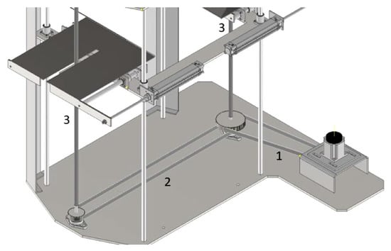
Figure 8.
Transmissions and movement ratio.
3.3.3. Selection of Pneumatic Actuators
The pneumatic actuators (see positioning of component 5, Figure 7) are responsible for maintaining the positioning of the package and the level of the handles supported by the leveled platform, which, moving horizontally, moves the support plates. The forces acting on the plate translate the mass of the bag when filled, acting horizontally, as well as the mass of the plate itself. The pneumatic actuator must ensure the positioning of the plate but it must also move the plate. Considering these two forces, their simplified representation is shown in Figure 9.
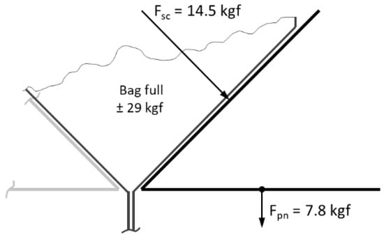
Figure 9.
Representation of the forces applied to the plates.
The calculation of the minimum internal diameter of the cylinder was obtained considering that it works in recoil. In this case, the diameter cannot be calculated directly, as it depends on both the diameter of the piston and the rod. The calculation was performed using the following expressions:
where dc is the minimum internal diameter of the cylinder [mm], Fp is the mass to move [kgf], η is the load factor, Pt is the working pressure [kgf/cm2] and A is the return area [cm2].
Considering the values of the forces acting on the linear actuators, the maximum mass of the packaged handles divided by two plates and the mass of each one, a minimum cylinder diameter to work in advance (12) is 20.14 mm. It was obtained, with a factor load capacity of 1 (horizontally guided cylinders), a working pressure of 7 bar and total mass to be moved, in the reverse direction, of 22.3 kgf per plate. As the diameter is not standardized, a 25 mm cylinder and 10 mm rod were chosen. However, the calculation that really interests us is the force that the cylinder must exert on recoil (13). After verifying the behavior of the cylinder in the retorn, a maximum value of 28.7 kgf was found, which guarantees, perfectly, the movement of fixation of the plates.
3.4. Counting System
All the concepts already dealt with are important for the concession of counting equipment. Dynamic analysis, being essential to define/analyze the operation of the equipment, together with the entire structural part, are means that define the structure of the packaging system. However, in addition to these operational and structural support elements, counting is the core of development since the counting process is the fundamental objective of the entire development and construction of the system. Thus, to carry out the counting and, consequently, the packaging, the handles must be directed through the connecting element of the vibrating bowl (1) to the support structure of the bags. A transport screen of reduced dimensions interconnects the two structures, guaranteeing not only the transport but also the counting of the handles. The final view of the developed packaging machine is shown in Figure 10. It is composed of the following parts:
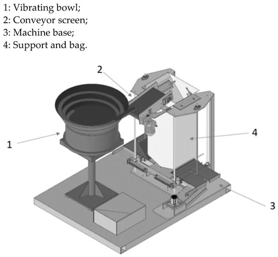
Figure 10.
Packing and handles counting system.
The handles deposited in the “bulk” in the vibrating bowl (1) are conducted to the handle transport system (2) where the count is performed until reaching the predefined count value in the human–machine interface (HMI). The system is controlled by a programmable logic controller (PLC), which also guarantees the protection of all mechanical organs and people, avoiding possible accidents and losses due to improper handling [18,19,20,21,22].
The handles, deposited in the vibrating bowl, are aligned, and positioned along the track of the bowl, gradually rising until they reach the end of the track. A sensor responsible for detecting the presence of the handles starts the transport system, starting the counting and transport of the handles to the mouth of the package. A guidance system directs the handles and a sensor positioned in the middle of the belt counts, one by one, the transported handles, as shown in Figure 11a. If the vibrating bowl sensor detects a lack of handles at the end of a certain period of time, the system interrupts the count, signaling it with a light signal. On the other hand, and to guarantee the quality of the packaged product, another sensor controls the level of the handles deposited in the mouth of the bag, guaranteeing the predefined maximum height, as shown in Figure 11b. This sensor is responsible for the order of descent of the level platform, allowing the entry of more handles.
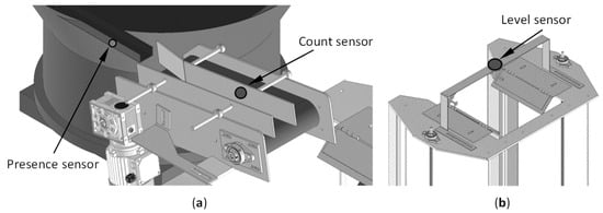
Figure 11.
(a) Packing and handle counting system, (b) Bag handle level sensor.
This robust counting system, governed by precise sensors and controlled by a programmable logic controller, ensures the accuracy and efficiency of the packaging process, minimizing errors and ensuring the quality of the final product.
Building upon the innovative developments detailed in Section 3 and Section 4 presents the results and analysis stemming from the implementation of the automated counting and packaging equipment. Despite meticulous planning and adherence to engineering methodologies, this chapter highlights the unforeseen challenges encountered during the commissioning phase and the subsequent adjustments made to ensure optimal functionality. It underscores the equipment’s resilience, its adaptive features and the substantial enhancements introduced to address unexpected issues.
4. Results and Analysis
Regardless of all the methodologies that were used in the development of the counting and packaging equipment, some adjustments had to be carried out in the commissioning phase. Thus, in the first test, a misalignment of the handle level platform was verified, caused by the weak fixation of one of the pulleys of the trapezoidal spindles, causing the structure to twist, since only one spindle moved. Despite all the control systems, vibrator and conveyor being operational, confirmed by the signals from the handle presence sensors and the counting sensor, a simple loosening led to the structure warping. Although not being the desired start, these occurrences served to test the emergence that corresponded perfectly.
The commissioning of the equipment proved to be crucial in detecting anomalies that had not even been considered in all the engineering methodologies used. The placement of an eccentric and a sensor at each end of the spindles solved not only the lack of tightness of the pulley in question but was also essential to detect failures in terms of movement, due to bursting of the belts or loss of teeth in the transmission belts or by wear of the pulleys, engine, and followers. Figure 12a shows a front view of the equipment showing the position of the open bag.
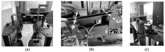
Figure 12.
(a) Bag and level sensor; (b) conveyor belt; (c) rotation sensor [7].
The level sensor is placed on the top bar. You can see the vibrating feeding bowl in the background. Figure 12b shows the conveyor belt that interconnects the vibrating bowl and the package structure. Counting is carried out approximately in the middle of this component. Finally, and to respond to possible anomalies related to the movement of the spindles, Figure 12c shows the sensor and the eccentric used to detect the rotation of the axes. This simple construction solved problems that could have been troublesome for the structure or even the machine operator.
Despite the correct functioning of the system, verified after alterations and adjustment of the components, the natural vibration of the vat and the wooden handles in direct contact with the metal produced too much noise. This noise, perceived in an industrial environment, is not essential for the packaging process. However, the vibration of the handles and the contact with the metal of the vat and the vibrating tracks can cause quality failures due to peeling of the varnish used to coat the handles. This was the factor that led to the coating of the vat and the vibrating tracks with a thin layer of rubber.
In the final tests of the equipment and with the amounts defined for each configuration of handles, very promising results were obtained. The handle leveling platform, controlled by the level sensor, perfectly controlled the fall height and the number of handles received at each step of the descent movement, as shown in Figure 13a. The sensor gave a lowering order as soon as the level inside the bag reached the mouth of the bag, moving on to the next step, ensuring the entry of more handless Figure 13b. This process continued to evolve in the following steps until the bag was completely filled to the amount predefined in the HMI, as shown in Figure 13c.
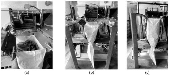
Figure 13.
(a) Handle counting system; (b) Initial level of handles; (c) Middle level of handles and sensor level [7].
All warning systems, equipment and operator protection responded promptly to requests induced in the process and uptimes were met. Operating gains became evident and the reduction in manpower costs was significant. Packing times were drastically reduced, as they were now carried out by a single operator who started to load the vibrating vat, remove the bag with the packed handless and place a new bag.
Section 4’s detailed analysis of the automated system’s performance sets the stage for Section 5, encapsulating the conclusions drawn from this innovative engineering endeavor. Emphasizing the successful culmination of the project, Section 5 highlights the significance of the developed equipment in revolutionizing the packaging process. Furthermore, it explores potential avenues for future enhancements and improvements, aiming to maximize operational efficiency and product quality, thus marking the beginning of a new phase of innovation and refinement in the industry.
5. Conclusions
Every engineering project requires meticulous planning and assessment to achieve its intended purpose. In the pursuit of enhancing every phase of the varnished wooden handle packaging system, various theoretical concepts were explored, supporting the system’s construction based on methodologies outlined in the VDI 2221 and VDI 2206 standards.
The adoption of these design methodologies led to an in-depth study of available systems in the market. This study, supported by a morphological analysis, facilitated the determination of the technology to be applied to the system. Notably, the mechatronic project, aligned with VDI 2206, gave rise to the complete control system developed in Ladder language, which is supported by a programmable logic controller (PLC).
The ultimate outcome of this development effort resulted in packaging equipment that ensures the automatic counting and packaging of varnished wooden handles without causing any damage. This solution effectively addressed all the company’s requisites and became a pivotal contribution to increasing production, effectively eliminating bottlenecks in the packaging operation.
In terms of future work, specific areas for enhancement have been identified. These involve improvements in soundproofing and security features, alongside the introduction of new operational modes aimed at making the system more adaptable and flexible. Further evolution prospects include the integration of a quality control system employing a vision system to detect anomalies in the handles, allowing for their removal or duplication of the vibrating vat tracks to double the system’s throughput.
Recommendations for Further Enhancement
- Detailed description of proposed enhancements: Expanding on the planned improvements would add depth to the conclusions. Elaborating on how the introduction of more flexible operational modes could benefit the system or explaining the specifics of implementing a vision-based quality control system would be beneficial.
- Consideration of feasibility: Discussing the feasibility and potential challenges of implementing these improvements within an industrial context, including costs, required resources and possible technical or operational obstacles would provide a more comprehensive understanding.
- Highlighting additional benefits: Emphasizing the additional benefits that these proposed enhancements might bring to production, the final product quality, operational efficiency or cost savings would reinforce the significance of the proposed improvements.
- Contextualizing impacts: Expanding on how these proposed improvements could positively impact production and company operations, showcasing how these changes might optimize industrial processes and yield tangible benefits would be advantageous.
In essence, this engineering venture stands as a testament to the effectiveness of robust methodologies and innovative design concepts in addressing industrial challenges. The developed packaging equipment, driven by meticulous design and rigorous testing, not only met the stipulated objectives but also exceeded expectations. Its successful integration into the production line marked a pivotal moment, significantly enhancing efficiency and streamlining the packaging process. Looking ahead, the identified areas for further refinement pave the way for future enhancements, reinforcing the commitment to continuous improvement and innovation. This culmination of efforts underscores the transformative impact of this project on the industry, positioning it as a beacon of modernization and efficiency in handle counting and packaging technology.
Author Contributions
Conceptualization, L.M. and J.M.; formal analysis, F.P., K.A. and J.M.; writing—original draft preparation, L.M., F.P. and A.A.S.; writing—review and editing, A.F.d.S., K.A. and J.M. All authors have read and agreed to the published version of the manuscript.
Funding
This work was partially financially supported by FCT—Fundação para a Ciência e Tecnologia (Portugal), who partially financially supported this work through the RD Units Project Scope: UIDP/04077/2020 and UIDB/04077/2020. The authors are grateful, too, to the partial financial support provided by Base Funding—UIDB/50022/2020 (LAETA) of INEGI—Institute of Science and Innovation in Mechanical and Industrial Engineering, Portugal.
Data Availability Statement
Data are contained within the article.
Conflicts of Interest
The authors declare no conflict of interest.
References
- Romadhon, A.; Widyaningrum, V. Automatic Food Packaging System using Programmable Logic Controller. In Proceedings of the International Conference on Health Informatics, Medical, Biological Engineering, and Pharmaceutical (HIMBEP 2020), Medan, Indonesia, 24–25 September 2020; pp. 271–277. [Google Scholar]
- Izarra-Cano, B.R.; Castro-Osores, L.G.; Blas-Yaringaño, C.A.; Huamanchahua, D. Design of an Automated Dosing and Mixing System for the Production of Biodegradable Biomass Based on Sweet Potato Starch and Sugar Cane Fiber. In Proceedings of the 2023 7th International Conference on Robotics, Control and Automation (ICRCA), Taizhou, China, 5–7 January 2023; pp. 83–86. [Google Scholar]
- Lwin, H.Y.; Htay, U.H.M. Design and Simulation of Automated Packaging Machine Process Control by Using PLC. Int. J. Trend Sci. Res. Dev. 2019, 3, 1423–1426. [Google Scholar]
- Paul, J.E.; Leena, G. Cost Efficient Automatic Filling System for Differently Sized Bottles. In Proceedings of the 2022 International Conference on Recent Trends in Microelectronics, Automation, Computing and Communications Systems (ICMACC), Hyderabad, India, 28–30 December 2022; pp. 288–293. [Google Scholar]
- Parcesepe, M.; Forgione, F.; Ciampi, C.M.; De Nisco Ciarcia, G.; Guerriero, V.; Iannotti, M.; Saviano, L.; Melisi, M.L.; Rampone, S. Towards the automated evaluation of product packaging in the Food & Beverage sector through data science/machine learning methods. Qual. Quant. 2023, 57, 2269–2280. [Google Scholar]
- FabriCabos. Available online: https://www.fabricabos.pt/ (accessed on 10 December 2023).
- Magalhães, L. Elaboração do Projeto de uma Máquina de Contagem de CABOS Automático. Master’s Thesis, University of Minho, Guimarães, Portugal, 2023. [Google Scholar]
- Senzani Brevetti Spa. Available online: https://www.senzani.com/en/sectors/ (accessed on 1 December 2023).
- Karlville Swiss. Available online: https://www.kvswiss.com/spout-inserting/ks-aspi-30/ (accessed on 8 December 2023).
- Imanpack. Available online: https://www.imanpack.com/Default.aspx (accessed on 9 December 2023).
- Tulkoff, C.; Caswell, G. Design for Excellence in Electronics Manufacturing; Wiley Series in Quality & Reliability Engineering; Wiley: Hoboken, NJ, USA, 2021. [Google Scholar]
- Velling, A. Design for X (DFX) Methods. 2021. Available online: https://fractory.com/design-for-x-dfx/ (accessed on 3 December 2023).
- Gausemeier, J.; Moehringer, S. New guideline vdi 2206-a flexible procedure model for the design of mechatronic systems. In Proceedings of the DS 31: Proceedings of ICED 03, the 14th International Conference on Engineering Design, Stockholm, Sweden, 19–21 August 2003. [Google Scholar]
- VDI 2221 Blatt 1:2019-11: Design of Technical Products and Systems—MODEL of Product Design. Available online: https://www.beuth.de/en/technical-rule/vdi-2221-blatt-1/311603768 (accessed on 6 December 2023).
- Pahl, G.; Grote, K.-H.; Feldhusen, J.; Beitz, W. Projeto na Engenharia, 6th ed.; Edgard Blucher: São Paulo, Brazil, 2016. [Google Scholar]
- Barros, R. Influencia das Microestruturas Bainítica e Martensítica nas Propridades Tribológicas do Par Aço AISI/ASE 4340 e Liga Bronze-Alumínio 630. Master’s Thesis, Universidade Estadual Paulista, Guaratinguetá, Brazil, 2013. [Google Scholar]
- OMEGA Performance Timing Belt—Optibelt. Available online: https://www.optibelt.com/us/products/timing-belts-rubber/ (accessed on 7 December 2023).
- Arachchige, U.; Chandrasiri, S.; Wijenayake, A. Development of automated systems for the implementation of food processing. J. Res. Technol. Eng. 2022, 3, 8–18. [Google Scholar]
- Caldas, P.; Sousa, F.; Pereira, F.; Lopes, H.; Machado, J. Automatic system for yarn quality analysis by image processing. J. Braz. Soc. Mech. Sci. Eng. 2022, 44, 565. [Google Scholar] [CrossRef]
- Pereira, F.; Macedo, A.; Pinto, L.; Soares, F.; Vasconcelos, R.; Machado, J.; Carvalho, V. Intelligent Computer Vision System for Analysis and Characterization of Yarn Quality. Electronics 2023, 12, 236. [Google Scholar] [CrossRef]
- Saleem, E.K. Automatic Sorting, Counting and Bottle Filling System. 2012. Available online: https://www.researchgate.net/profile/Waheed-Ur-Rehman-6/publication/310800445_AUTOMATIC_SORTING_COUNTING_AND_BOTTLE_FILLING_SYSTEM/links/5838142f08ae3d91723d8cb3/AUTOMATIC-SORTING-COUNTING-AND-BOTTLE-FILLING-SYSTEM.pdf (accessed on 10 December 2023).
- Wagner, H.J.; Alvarez, M.; Groenewolt, A.; Menges, A. Towards digital automation flexibility in large-scale timber construction: Integrative robotic prefabrication and co-design of the BUGA Wood Pavilion. Constr. Robot. 2020, 4, 187–204. [Google Scholar] [CrossRef]
Disclaimer/Publisher’s Note: The statements, opinions and data contained in all publications are solely those of the individual author(s) and contributor(s) and not of MDPI and/or the editor(s). MDPI and/or the editor(s) disclaim responsibility for any injury to people or property resulting from any ideas, methods, instructions or products referred to in the content. |
© 2024 by the authors. Licensee MDPI, Basel, Switzerland. This article is an open access article distributed under the terms and conditions of the Creative Commons Attribution (CC BY) license (https://creativecommons.org/licenses/by/4.0/).