Article

Equivalent Continuum Modeling for Flexible Slender Quadrilateral Truss Structure

1
State Key Laboratory of Robotics and System, Harbin Institute of Technology, Harbin 150001, China
2
Laboratory of Test and Measurement Technology, Tianjin Institute of Aerospace Mechanical and Electrical Equipment, Tianjin 300301, China
3
Parallel Robot and Mechatronic System Laboratory of Hebei Province, Yanshan University, Qinhuangdao 066004, China
4
School of Astronautics, Harbin Institute of Technology, Harbin 150001, China
*
Author to whom correspondence should be addressed.
Machines 2024, 12(2), 111; https://doi.org/10.3390/machines12020111
Submission received: 3 January 2024 / Revised: 29 January 2024 / Accepted: 4 February 2024 / Published: 6 February 2024
(This article belongs to the Section Machine Design and Theory)

Abstract

:
A space in-orbit service simulation experiment platform is a type of equipment platform that allows spacecraft such as satellites and deep-space explorers to be adequately ground tested before launch. The function of the crane system is to drive the target spacecraft to perform a large-scale movement. This study focuses on the dynamics of a space in-orbit service simulation experiment platform with suspension rope and column quadrilateral truss structure as connecting devices. A space in-orbit service simulation experiment platform with a column quadrilateral truss structure as a connecting device is studied, modeled as a crane system–column quadrilateral truss structure–target spacecraft system. For the column quadrilateral truss structure, the equivalent beam model is used to make it equivalent based on the Timoshenko beam theory. The required equivalent stiffness parameters are determined and adjusted. The relative error between the finite element model and the corrected equivalent beam model of the column quadrilateral truss structure is no more than 4.7%. The results indicate that the accuracy of the modified equivalent beam model is sufficient. The improved equivalent beam model has excellent precision according to numerical calculations, and the derived equivalent stiffness parameters may be employed directly in dynamic modeling.

1. Introduction

In the complex space environment, determining how to ensure the stable in-orbit operation and attitude control of spacecraft has become a major technical problem to be solved. A variety of large space in-orbit servicing platforms and large ground simulation test equipment can effectively simulate the attitude and motion of spacecraft on the ground and verify the feasibility of the control system and related schemes. Due to the large scale and complicated structure of various spacecraft, launch costs are becoming increasingly expensive. To save cost on space missions, ground in-orbit service test platforms have become widely used in the space field. The requirements for the control precision and vibration analysis of space test equipment are growing stricter [1]. Therefore, before and during the design of a ground in-orbit service test platform, simulation tests and comparisons are needed to verify the feasibility of the design. Considering various safety factors, error analysis must be performed to determine the most important reasons whenever the test results cannot meet the requirements so that the conceptual and the mission design objectives can be modified. At present, the mainstream processing methods are micropolar beam theory, the finite element (FE) method, and the equivalent beam principle. In a space in-orbit service simulation test platform the equivalent beam principle is typically used for the rigid connected large-space flexible four-prismatic truss–column structure. The column quadrilateral truss structure (QTS) is the connecting device. The truss flexible body dynamic model method often uses the FE method. Substantial elements and high order are needed for a refined structure model. However, the order of the FE model needs to be lowered.
Arndt [2] first applied the adaptive generalized FE method to free vibration analysis of a slender truss. Chung [3] established the dynamic model of a rigid–flexible coupling system of a spacecraft with flexible attachment and discretized the system. The relationship between rotation and vibration deformation of a slender truss structure equivalent beam was studied. Hu [4] analyzed the dynamic model of a large-scale space truss structure in the development process as well as after expansion and locking. The nonlinear ring truss structure after expansion was a complex high-dimensional system. The homogenization method was used to model the flexible truss structure, which was transformed into the equivalent continuum beam model based on the energy equivalent principle. Micropolar beam theory was first proposed by Noor [5,6,7]. This theory considers the in-plane bending of a rigid truss structure and uses the micropolar beam continuum to accurately simulate the vibration response of the truss element. The eigenvector and principal vector of the state transition matrix were used to homogenize the truss element, and a direct method was proposed for the beam structure [8,9]. Liu [10] studied the method of a repeating truss structure equivalent beam continuum model considering the flexibility of nodes. Liu [11] further proposed an equivalent beam model that considered the warping of the repeated element cross section. Cao [12] proposed a method for extending the continuum model to an elongated truss structure with geometric nonlinearity. Zhang [13] analyzed the truss structure vibration of a large deployable ring mesh antenna held by a busbar. A simplified method was proposed to reduce the three-dimensional element structure to a two-dimensional flat element structure with a ring truss. Bai [14] studied the large articulated truss structure dynamics, analyzed the influence of three nonlinear nodes on the dynamic behavior of an articulated truss, and established the equivalent dynamic model of the truss element. Based on the idea of continuum equivalence, Liu [15] considered shear isotropic elastic rings as equivalent to a flexible ring truss. The dynamic response was solved using an analytic equation equivalent to a ring, and the truss FE model was compared. Based on the principle of energy reciprocity and classical Timoshenko beam theory, Cao [16] analyzed the truss structure equivalent model and dynamics of a large space triangular prism. Equivalent beam theory was proven to be more accurate than micropolar beam theory. Song [17] proposed a correction method to deal with the nonlinear stiffness in the truss structure using the pattern search method. The results showed that this method has high accuracy. Many scholars [18,19,20] have conducted considerable research on the deflection of flexible truss structures in spacecraft, along with vibration analysis and control methods. The equivalent beam theory, simplified from the micropolar beam principle, is suitable for the dynamic modeling of space column truss structures in a whole system.
Space in-orbit service simulation test platforms are applied to conduct ground equivalent simulated testing of the in-orbit dynamics of the spacecraft capturing process. The extreme space environment has little effect on spacecraft dynamics in orbit. A dynamic model of a space in-orbit service simulation test platform with a column truss structure as connecting device is first established. A separate dynamic model is then adopted for the column truss structure of the connecting device. The equivalent beam principle is used to obtain the flexible truss structure equivalent elastic parameter and modify it. The accuracy and feasibility of the equivalent elastic parameter are verified by modal analysis of the equivalent beam and actual truss structure. In the structure of crane system–cantilever beam–target vehicle system, the cantilever moving load is simply considered as a Euler–Bernoulli beam and a dynamic model is utilized. However, in actual engineering the suspension load of the space in-orbit service simulation test platform system is concentrated on the mechanical arm or space truss structure. This type of structure is more complex in the dynamic model. This work studies the typical space column truss structure equivalent model problem. After the equivalent elastic parameter and equivalent inertia parameter of the flexible truss slender structure are obtained, it is substituted into the dynamic model of the whole system. The accurate dynamic model is then applied to the whole system.

2. Equivalent Method for Timoshenko Beam

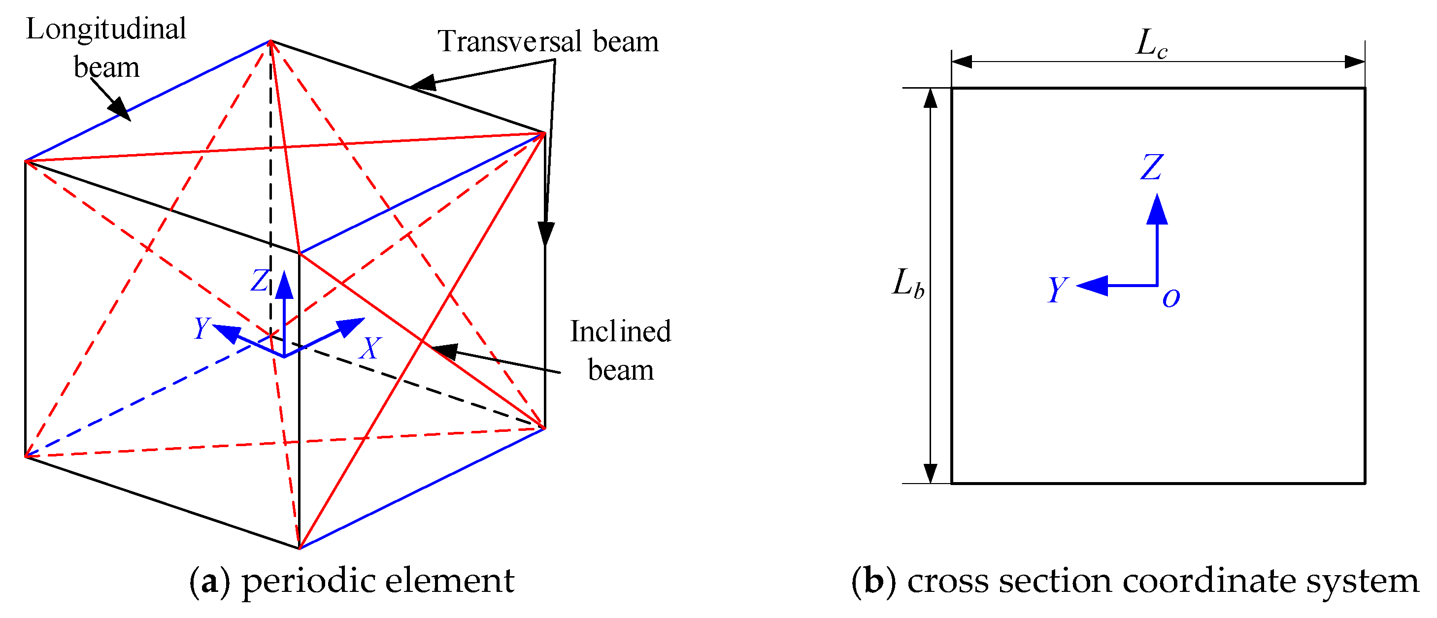
The typical truss column moving load model in the test platform is shown in Figure 1. The flexibility of the truss structure cannot be ignored when carrying out a large range of three-dimensional motion. The elongated space flexible truss structure and elongated flexible continuum beam have similar dynamic characteristics. Therefore, the slender flexible truss structure is equivalent to the continuum beam model, which can describe the whole dynamic characteristics of flexible truss and simplify the model. The space truss structure is equivalent to a Timoshenko continuum beam of the same length, and the feasibility of the equivalent model is verified by modal analysis.
The elastic potential energy and kinetic energy of the periodic element in flexible QTS are respectively equivalent to the elastic potential energy and kinetic energy of the equivalent continuum beam of the same length, which is the energy equivalence principle. The displacement pattern is established first for the flexible QTS periodic element. The periodic element strain field and element elastic potential energy are calculated according to their geometric relation. Based on the periodic element displacement pattern, the velocity field within the element is calculated, then the element kinetic energy is solved. Through the energy equivalent and continuum mechanic theory, elastic potential energy, and kinetic energy for a Timoshenko beam of the same length are obtained and the equivalent parameters of the continuum beam are acquired. The flowchart of the equivalent beam model is shown in Figure 2.

2.1. Displacement Mode of the Periodic Element

Figure 3a shows the column QTS periodic element in the space in-orbit service simulation test platform. It is welded by 20 beam components, including four longitudinal beams, eight transverse beams, and eight inclined beams. Each beam component is fixedly connected. No mutual constraint exists between two inclined beams on the same plane. According to the equivalent beam theory in the previous section, the displacement pattern at any point within the periodic element needs to be calculated. If any cross-section in the periodic element remains flat before and after deformation, the wrapping and some bending modes of the cross-sections are not considered. Then, the displacement of any point on the plane can be expressed by the cross–section’s center displacement and deformation linearity, as shown in Figure 3b. A right-handed coordinate system o–xyz is established at the center of any plane in the space element. Accordingly, the displacement [21] of any point on it can be expressed as follows:
{ u x ( x , y , z ) = u x 0 ( x ) + z θ y 0 ( x ) y θ z 0 ( x ) u y ( x , y , z ) = u y 0 ( x ) z θ x 0 ( x ) + y ε y 0 ( x ) + 1 2 z γ y z 0 ( x ) u z ( x , y , z ) = u z 0 ( x ) + y θ x 0 ( x ) + z ε z 0 ( x ) + 1 2 y γ y z 0 ( x )
where ux0, uy0, and uz0 are the displacements along the x-, y-, and z-axes of the periodic element center (y = 0, z = 0), respectively, θx0, θy0, and θz0 are the rotation angles around the x-, y-, and z-axes of the periodic element center, respectively, εx0, εy0, and εz0 are the positive strains along the x-, y-, and z-axes of the periodic element center, respectively, and γxy0 and γyz0 are the shear strain of the periodic element.
If the displacement of any point in the periodic element is Taylor expanded at the periodic element center and the derivative term of the strain is ignored, then
{ u x ( x , y , z ) = u x 0 y θ z 0 + z θ y 0 + x ε x 0 x y κ y 0 + x z κ z 0 u y ( x , y , z ) = u y 0 + y ε y 0 + z ( θ x 0 + 1 2 γ y z 0 ) + x ( θ z 0 + γ x y 0 ) x z κ x 0 + 1 2 x 2 κ y 0 u z ( x , y , z ) = u z 0 + y [ θ x 0 + 1 2 γ y z 0 ] + z ε z 0 + x ( γ x z 0 θ y 0 ) + x y κ x 0 1 2 x 2 κ z 0
where κx0, κy0, and κz0 are the curvature along the three axes of the periodic element center, respectively.
The periodic element exists at the center with the following geometric equation.
{ ε x 0 = u x 0 ( x ) x x = 0 , ε y 0 = u y 0 ( x ) x , ε z 0 = u z 0 ( x ) x κ x 0 = θ x 0 ( x ) x , κ y 0 = θ z 0 ( x ) x , κ z 0 = θ z 0 ( x ) x γ x y 0 = u y 0 ( x ) x θ z 0 ( x ) , γ x z 0 = u z 0 ( x ) x + θ y 0 ( x )
Based on the continuum beam deformation geometric equation, the following equation can be derived.
{ θ x ( x , y , z ) = 1 2 ( u z y u y z ) = θ x 0 + x κ x 0 θ y ( x , y , z ) = 1 2 ( u x z u z x ) = θ y 0 + x κ z 0 1 2 γ x z 0 1 2 y κ y 0 θ z ( x , y , z ) = 1 2 ( u y x u x y ) = θ z 0 + x κ y 0 + 1 2 γ x y 0 1 2 z κ x 0
Compared to the micropolar beam theory proposed by Noor, equivalent beam theory ignores the microrotation of the fixed joint and simplifies the calculation process. However, the bend curvature and the effect on structure transverse bend displacement and deformation during Taylor expansion development need to be considered. The method is suitable for rigid jointed processes with periodic QTS equivalent.

2.2. Elastic Potential and Kinetic Energy of the Periodic Element

The periodic element total potential energy of the space QTS is the total of all components’ elastic potential energy in the periodic element. The total kinetic energy of the periodic element refers to of all components’ kinetic energy in the periodic element:
U = e U e , T = e T e
where e is the number of components; Ue is the elastic potential energy of the e-th components, which includes the bend potential energy, vertical bend potential energy, axial tension and compression potential energy, and torsional potential energy of each transverse component; and Te is the kinetic energy of the e-th component.
Using the FE method, each component field displacement is obtained by the boundary displacement interpolation of the beam component. Then, its elastic potential energy and kinetic energy are as follows:
U e = U e ( u ) + U e ( v ) + U e ( w ) + U e ( ϑ )
T e = T e ( u ) + T e ( v ) + T e ( w ) + T e ( ϑ )
where U e ( u ) , U e ( v ) , U e ( w ) , and U e ( ϑ ) are respectively the axial tension and compression potential energy, transverse bend potential energy, vertical bend potential energy, and torsional potential energy of each component and T e ( u ) , T e ( v ) , T e ( w ) , and T e ( ϑ ) are respectively the axial tension and compression kinetic energy, transverse bend kinetic energy, vertical bend kinetic energy, and torsional kinetic energy of each component. The 6-DOF displacement of the i-th (i = 1, 2) boundary of the e-th beam element is represented by q i e = [ u x i e u y i e u z i e θ x i e θ y i e θ z i e ] T , where u, v, and w are respectively the axial dimension and transverse and vertical directions of the cross section, while θ represents the torsion angle of the cross-section.
According to the FE method, the elastic potential energy and kinetic energy of the e-th beam element are written as follows:
U e = 1 2 q e T k e q e , T e = 1 2 q ˙ e T M e q ˙ e
where qe is the boundary displacement of the e-th beam element in the local coordinate system, q e = [ q 0 e T q 1 e T ] T , while Ke is the element stiffness matrix and Me is the element mass matrix.
Because the transverse beam is shared by two adjacent periodic elements, the geometric parameter and mass parameter of the transverse beam cross-section are each regarded as half of the calculation. In a similar way, the transverse beam is shared by two adjacent periodic elements; thus, the geometric parameter and mass parameter of the transverse beam cross-section are regarded as halves as well. Considering that the direction of each element’s local coordinate system in the beam system is different, all of them need to be transformed into the displacement under the global coordinate system during the structural analysis, which can be written as follows:
q e = Γ q ^ e
where q ^ e is the nodes’ displacement in the global coordinate system.
The transformation matrix from the global coordinate system to the component local coordinate system is Γ, and the 3–2–1 Euler angle can be used to represent its transformation matrix, which is written as follows:
Γ = [ λ 0 0 0 0 λ 0 0 0 0 λ 0 0 0 0 λ ]
where
λ = [ cos θ 1 cos θ 3 cos θ 2 sin θ 3 sin θ 2 cos θ 1 sin θ 3 + sin θ 1 sin θ 2 cos θ 3 cos θ 1 cos θ 3 + sin θ 1 sin θ 2 sin θ 3 sin θ 1 cos θ 2 sin θ 1 sin θ 3 + cos θ 1 sin θ 2 cos θ 3 sin θ 1 cos θ 3 + cos θ 1 sin θ 2 sin θ 3 cos θ 1 cos θ 2 ]
where θ3, θ2, and θ1 represent the rotation angle along the z-, y-, and z-axes in the global coordinate system, respectively.
Then, the stiffness matrix and mass matrix in the global coordinate system are derived as follows.
K ^ e = Γ e T K e Γ e
M ^ e = Γ e T M e Γ e
The periodic element elastic potential energy and kinetic energy can be derived as follows.
U = 1 2 e q ^ e T K ^ e q ^ e
K = 1 2 e q ^ ˙ e T M ^ e q ^ ˙ e
The displacement of any point within the periodic element can be represented by the displacement and strain at the periodic element center. When calculating the periodic element elastic potential energy, the rigid body displacement term in the displacement expression is ignored, i.e.,
[ u x k u y k u z k θ x k θ y k θ z k ] = [ x 0 0 0 0 0 0 x y x z 0 y 0 x 0 1 2 z x z 1 2 x 2 0 0 0 z 0 x 1 2 y x y 0 1 2 x 2 0 0 0 0 0 0 x 0 0 0 0 0 0 1 2 0 1 2 y 0 x 0 0 0 1 2 0 0 1 2 z x 0 ] [ ε x 0 ε y 0 ε z 0 γ x y 0 γ x z 0 γ y z 0 κ x 0 κ y 0 κ z 0 ] = L c [ ε x 0 ε y 0 ε z 0 γ x y 0 γ x z 0 γ y z 0 κ x 0 κ y 0 κ z 0 ]
where x k = [ u x k u y k u z k θ x k θ y k θ z k ] T is a displacement vector at the material point and x, y, and z are the position coordinates of a material point in the periodic element coordinate system.
According to the classical beam theory, no mutual extrusion occurs between the layers of the cross-section, and the beam model is equivalent to the equivalent periodic element, i.e.,
U ε y 0 = U ε z 0 = U γ y z 0 = 0 .
According to Equation (17), the potential energy of the periodic element can be written as a function of εx0, γxo, γxz0, κx0, κy0, and κz0, with ε = [εx0, γxo, γxz0, κx0, κy0, κz0]T.
The periodic element potential energy U can be written as follows:
U = 1 2 ε T D c ε
where Dc is the stiffness matrix.
When calculating the periodic element kinetic energy, because the rigid body motion is the main component of the kinetic energy, the strain term in the displacement expression can be ignored, as shown below.
x k = [ u k v k w k θ x k θ y k θ z k ] = [ 1 0 0 0 z y 0 1 0 z 0 x 0 0 1 y x 0 0 0 0 1 0 0 0 0 0 0 1 0 0 0 0 0 0 1 ] [ u x 0 u y 0 u z 0 θ x 0 θ y 0 θ z 0 ] = L b [ u x 0 u y 0 u z 0 θ x 0 θ y 0 θ z 0 ]
The same condition applies to the elastic potential energy of the periodic element, which can be collectively referred to as the positioning matrix. The displacement at each material point within the periodic element can be found by locating the displacement or stress at the matrix and the periodic element center. The kinetic energy of the periodic element can be written as the function of ux0, uyo, uz0, θx0, θy0, and θz0, i.e., u= [ux0, uyo, uz0, θx0, θy0, θz0]T, while the kinetic energy can be derived as follows.
T = 1 2 u ˙ T M c u ˙

2.3. Elastic Potential Energy and Kinetic Energy of an Equivalent Beam

This study considers an equivalent Timoshenko continuum beam which has the same length Ll as the truss periodic element. The total elastic potential energy and total kinetic energy of the periodic element are equal to those of the Timoshenko continuum beam. The expressions of the elastic potential energy and kinetic energy obtained by calculation show that the coupling terms exist in deformation. Given that the periodic truss element equivalent of continuum beam is a short and thick beam, the span height ratio is approximately 1. Therefore, the QTS should be equivalent to the anisotropic Timoshenko beam. According to continuum mechanics, the continuum beam elastic potential energy U ^ is written as follows:
U ^ = 1 2 L l Χ T D Χ d x
where X = [εx0, γxyo, γxz0, κx0, κy0, κz0]T is the strain vector at the central axis of the equivalent continuum beam. Because the derivative term of strain is ignored, the strain on the neutral axis of the equivalent beam can be regarded as the constant strain, which is equal to the strain at the periodic element center. Here, D is the elastic matrix,
D = [ E A η 12 η 13 η 14 η 15 η 16 G A y η 23 η 24 η 25 η 26 G A z η 34 η 35 η 36 G J η 45 η 46 E I z η 56 s y m E I y ]
where EA is the compressive stiffness of the anisotropic beam, GAy and GAz are the shear stiffness of the anisotropic beam, GJ is the anisotropic beam torsional stiffness, EIz and EIy are the anisotropic beam bend stiffness, and ηij is the coupling stiffness; some of these terms may be zero depending on whether or not the spatial truss element is symmetrical.
According to the equivalent beam principle, the potential energy U of the QTS is equal to the equivalent anisotropic beam, shown below:
U = U ^
From the above equations, a certain relationship exists between the matrices Dc and D, as follows:
{ E A = D 11 L l , G A y = D 22 L l , G A z = D 33 L l G J = D 44 L l , E I z = D 55 L l , E I y = D 66 L l
where Dij is the element in matrix D.
The kinetic energy of the flexible truss periodic element for the anisotropic Timoshenko beam is as follows:
T ^ = 1 2 L l δ ˙ T M δ ˙ d x
where δ = [ux0, uyo, uz0, θx0, θy0, θz0]T is the displacement vector along the neutral axis of the beam.
The periodic element strain term is ignored, and only the rigid body displacement of the periodic element is considered. The periodic element and equivalent beam model with constant velocity on the neutral axis is
M = [ m c m 12 m 13 m 14 m 15 m 16 m c m 23 m 24 m 25 m 26 m c m 34 m 35 m 36 J x m 45 m 46 J y m 56 s y m J z ]
where mc is the linear density of the anisotropic Timoshenko beam and Jx, Jy, and Jz are the moments of inertia around the x-, y-, and z-axes of the unit length beam, respectively.
The kinetic energy of the QTS is equal to the kinetic energy of the equivalent anisotropic beam, i.e.,
T = T ^ .
The relationship between the matrix Mc and elastic matrix M can be written as
m c = m 11 L l = m 22 L l = m 33 L l , J x = m 44 L l , J y = m 55 L l , J z = m 66 L l ,
where Mij is the element in matrix Mc.

3. Equivalent Beam Model of QTS

3.1. Equivalent Beam Model Parameters of QTS

The column QTS in the space in-orbit platform is shown in Figure 4a; it consists of 12 periodic elements, as depicted in Figure 4b. Each periodic element is welded from 20 components. The column QTS of the space in-orbit service simulation test platform can be approximated as a cantilever structure. According to the component cross-section parameter in the actual QTS, the equivalent beam principle is used to calculate the equivalent elastic parameter of the flexible QTS. The equivalent elastic parameter is corrected using modal frequency equality. The material parameters of the component in the periodic element are listed in Table 1.
According to the equivalent beam model in the Section 2.3, the column QTS in the space in-orbit service simulation test platform is equivalent, and the elastic matrix and inertia matrix are obtained. Based on the equivalent beam principle, the elastic potential energy and the kinetic energy of the QTS periodic element are equal to the elastic potential energy and kinetic energy of the equivalent beam for the same length. The corresponding stiffness and mass parameters are as follows.
E A = 27.14 × 10 8 , G J = 75.94 × 10 8 , E I z = 61.55 × 10 8 , E I y = 62.55 × 10 8 m c = 639.61 , J x = 245.41 , J y = 256.53 , J z = 189.37

3.2. FE Discretization of Equivalent Beam

The equivalent beam stiffness matrix and mass matrix are calculated using the FE method. The column QTS of the space in-orbit service simulation test platform is a cantilever structure, and its constraint condition is
{ w ( 0 ) = 0 , w ( l ) = 0 , v ( 0 ) = 0 , v ( l ) = 0 w ( 0 ) = 0 , w ( l ) = 0 , v ( 0 ) = 0 , v ( l ) = 0 .
The space QTS is equivalent to the anisotropic Timoshenko beam. The two-node Timoshenko beam model has a displacement matrix of 16 DOFs, and each node has 8 DOFs:
δ i = [ u 0 i v b 0 i v s 0 i w b 0 i w s 0 i θ x 0 i θ y 0 i θ z 0 i ] T .
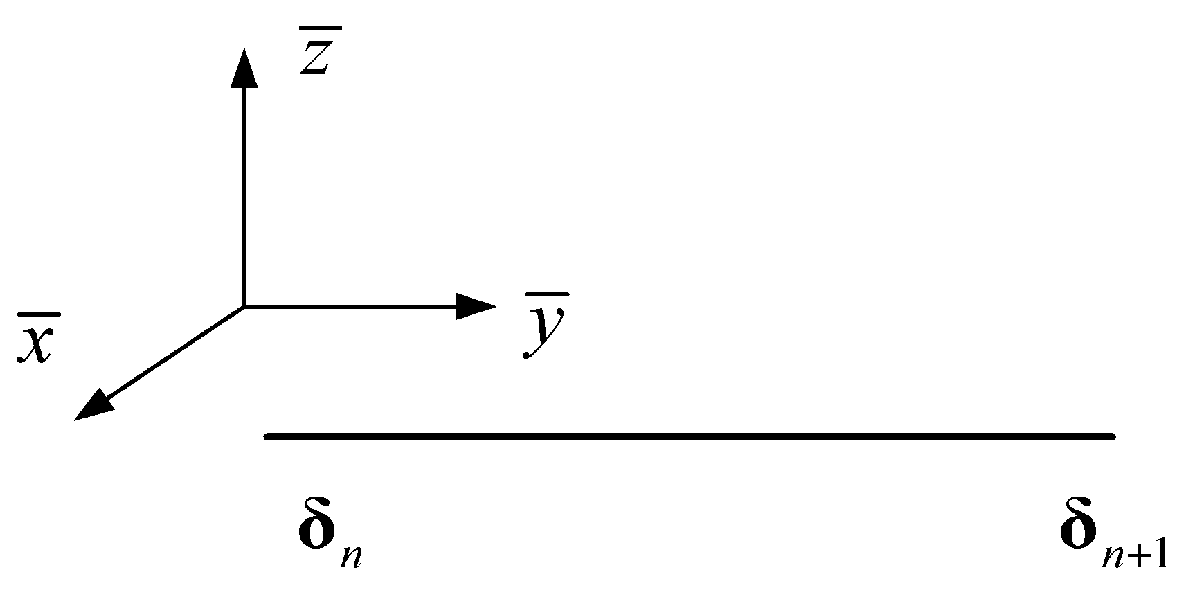
For any element on the cantilever equivalent beam, the left and the right node displacement arrays are δn and δn+1, respectively. The local coordinate system is shown in Figure 5.
Under the local coordinate system, the internal displacement of the beam element can be obtained by displacement interpolation of the element node. According to Timoshenko beam theory, the beam transverse (vertical) vibration displacement is composed of transverse (vertical) bend vibration and transverse (vertical) shear vibration, namely,
{ v = v s + v b w = w s + w b .
The bend displacement and shear displacement are interpolated independently, then
{ u = N 1 u 0 i + N 2 u 0 j v b = N 3 v b 0 i + N 4 θ z 0 i + N 5 v b 0 j + N 6 θ z 0 j v s = N 1 v s 0 i + N 2 v s 0 j w b = N 3 w b 0 i + N 4 θ y 0 i + N 5 w b 0 j + N 6 θ y 0 j w s = N 1 w s 0 i + N 2 w s 0 j θ x = N 1 θ x 0 i + N 2 θ x 0 j ,
where N1, N2, …, N6 are the corresponding form function, which can be written as follows:
{ N 1 = 1 ξ ,     N 2 = ξ , N 3 = 1 3 ξ 2 + 2 ξ 3 , N 4 = ( ξ 2 ξ 2 + ξ 3 ) l N 5 = 3 ξ 2 2 ξ 3 ,     N 6 = ( ξ 3 ξ 2 ) l
where ξ is the normalized coordinate along the direction of the equivalent beam length ξ = x ¯ / l , x ¯ is the local coordinate, and l is the element length.
The displacement vector of any point in the element is represented by u = [u vb vs wb ws θx]T, which can be derived by
{ N 1 = 1 ξ ,     N 2 = ξ , N 3 = 1 3 ξ 2 + 2 ξ 3 , N 4 = ( ξ 2 ξ 2 + ξ 3 ) l N 5 = 3 ξ 2 2 ξ 3 ,     N 6 = ( ξ 3 ξ 2 ) l ,
where δ = [ δ n T δ n + 1 T ] T is the node displacement of the beam element and N is the form function matrix of the element:
N = ( N 1 0 0 0 0 0 0 0 N 2 0 0 0 0 0 0 0 0 N 3 0 0 0 0 0 N 4 0 N 5 0 0 0 0 0 N 6 0 0 N 1 0 0 0 0 0 0 0 N 2 0 0 0 0 0 0 0 0 N 3 0 0 N 4 0 0 0 0 N 5 0 0 N 6 0 0 0 0 0 N 1 0 0 0 0 0 0 0 N 2 0 0 0 0 0 0 0 0 N 1 0 0 0 0 0 0 0 N 2 0 0 ) .
Based on the strain–displacement relation in the FE method, the following equation can be derived:
{ ε x = d u d x , γ x y = d v s d x , γ x z = d w s d x κ x = d θ x d x , κ y = d 2 v b d x 2 , κ z = d 2 w b d x 2 .
The strain within this element is written as follows:
ε = { ε x γ x y γ x z κ x κ y κ z } T = L N δ
where L is a differential operator describing geometric relations, which can be written as
L = ( d d x 0 0 0 0 0 0 0 d d x 0 0 0 0 0 0 0 d d x 0 0 0 0 0 0 d d x 0 d 2 d 2 x 0 0 0 0 0 0 0 d 2 d 2 x 0 0 ) .
The strain matrix is B = LN, which represents the relationship between strain and node displacement on the neutral axis of the element. According to the FE method, the beam element stiffness matrix and mass matrix are derived as follows.
{ K e = 0 l Β T D c Β   d x M e = 0 l N T M c N   d x
Likewise, the whole-space equivalent beam stiffness matrix is equal to the sum of all elements’ stiffness matrix.
K = K e
Moreover, the whole-space equivalent beam mass matrix is equal to the sum of all elements’ mass matrix.
M = M e
Note that when assembling the total body stiffness matrix and total body mass matrix the element matrix needs to be reassembled according to the element node position. At the same time, the stiffness matrix and mass matrix considering the constraint condition Equation (41) are calculated to solve the QTS dynamics.

3.3. Modal Analysis Based on the FE Method

According to the FE method of space equivalent beam, the dynamic equation of the system without damping is written as follows.
M δ ¨ + K δ = 0
Based on the boundary constraints of the cantilever beam and assuming the modal method, the characteristic equation of Equation (42) is written as follows.
( K ω 2 M ) φ = 0
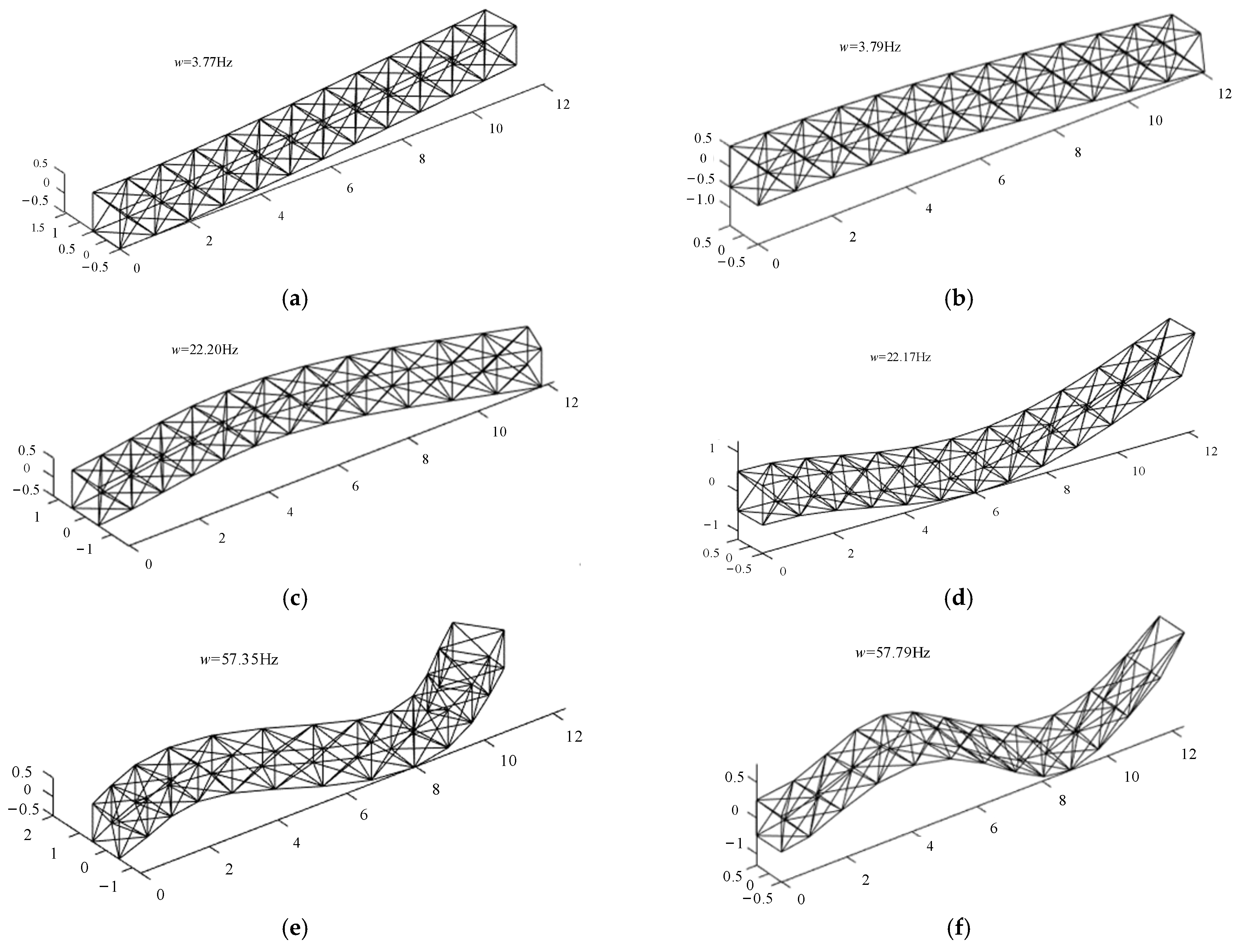
From Equation (43), the natural and modal frequencies of the equivalent beam can be obtained to analyze the dynamic characteristics of the system. The equivalent beam is divided into 12 elements, of which the longitudinal length without external loading is 12 m. The constraint condition is in cantilever beam form. Matlab 2019a software was used to carry out the numerical analysis and perform simulations. The first six orders of the bending vibration mode of the theoretical equivalent beam are shown in Figure 6.
From Figure 6 to Figure 7, it can be seen that the vertical bend and the modes of the first three orders in the torsional position of the actual QTS transverse bend fit well using the equivalent beam principle.
According to the analysis in Table 2, the relative frequency errors RE1 corresponding to the vertical bend, torsional and axial tension, and compression are relatively large at more than 10%. Nevertheless, the relative error decreases with the increase in order. The relative error mainly comes from the following aspects: (1) the slender QTS is different from the local equivalent continuum beam, especially when torsional and shear deformation occurs; (2) when calculating the periodic element elastic potential energy, the strain on the neutral axis of the periodic element is regarded as a constant, while when calculating the periodic element kinetic energy only the rigid body motion of the periodic element is considered; and (3) when calculating the transverse beam potential energy in the element, two adjacent periodic elements share a transverse beam. Hence, one half of the transverse beam parameter is taken, but not the half of the transverse beam parameter on the other side of the boundary of the periodic element. From Table 2, the equivalent beam method of QTS is not accurate. Thus, the equivalent elastic or mass parameters of the equivalent beam model need to be revised.

3.4. Modification of the Equivalent Beam Model

For the study of the QTS dynamics, its equivalent elastic parameter is important. Inaccuracy of the equivalent elastic parameter can lead to large relative error during dynamic analysis. The equivalent mass coefficient has a minimal effect on the dynamic problem; therefore, the equivalent elastic parameter is mainly corrected.
The slender truss structure is quite different from the equivalent continuous beam in the local area, especially when torsion and shear occur. When calculating the elastic potential energy of the periodic element, the strain on the neutral axis of the periodic element is regarded as a constant. When calculating the kinetic energy of the periodic element, only the rigid body motion of the periodic element is considered, which has some error in comparison with the actual results. When calculating the potential energy of the beam in the cell, considering that two adjacent periodic elements share a beam, the beam parameter is selected as half of the original. However, the beam parameter on one side of the boundary periodic element is not used as half of the original, resulting in a certain error. The effect of the equivalent mass coefficient on the dynamics problem is very small, and the inaccuracy of the equivalent elastic parameters can lead to large errors in the dynamics research; thus, the equivalent elastic parameters are mainly modified.
Considering that the QTS is a cantilever beam structure under ideal conditions, the equivalent beam bend along with the torsional and even axial vibration frequencies should be the same as the corresponding vibration frequencies of a cantilever QTS. On this basis, the equivalent elastic parameter is revised in this work. For the cantilever form of the continuum beam, its bend vibration frequency is
ω n = ( β n l ) 2 l 2 E I ρ A ,
where βnl is the n th-order solution of the transcendental equation, with βnl = 1.875.
The linear density mc in the inertia matrix is calculated using the equivalent beam model. The vibration frequency w n of the QTS is equal to the vibration frequency wn of the equivalent beam model, which can be written as
ω 1 = ω 1 = 1.875 2 l 2 E I m c .
After Equation (45) is solved, the corrected bend stiffness E I can be obtained. Similarly, the transverse bend stiffness E I z , vertical bend stiffness E I y , and beam axial vibration frequency of the cantilever can be derived as follows:
ω n = n π 2 l E A m c .
For a given mc, the first-order axial vibration frequency can be made equal to that of the actual QTS to obtain the corrected axial stiffness E A . The beam torsional vibration frequency of the cantilever can then be derived as follows.
ω n = n π 2 l G J J x
After Equation (47) is solved, the corrected torsional stiffness GJ′ is obtained. According to the above calculation, the correction can be accomplished by replacing the corrected EA′, EIz, EIy′, and GJ′ with their counterparts in the elastic matrix.

4. Discussion

The boundary condition of the column QTS in the space in-orbit service simulation test platform is the cantilever beam model. The column QTS equivalent elastic matrix of the space in-orbit service simulation test platform is modified. According to the calculation in Section 3, the compression, bend, and stiffness of the torsional cross-sections are modified for the QTS equivalent beam model. The corrected equivalent elastic parameters are obtained as follows.
E A = 27.34 × 10 8 , G J = 80.78 × 10 8 , E I z = 47.49 × 10 8 , E I y = 47.75 × 10 8
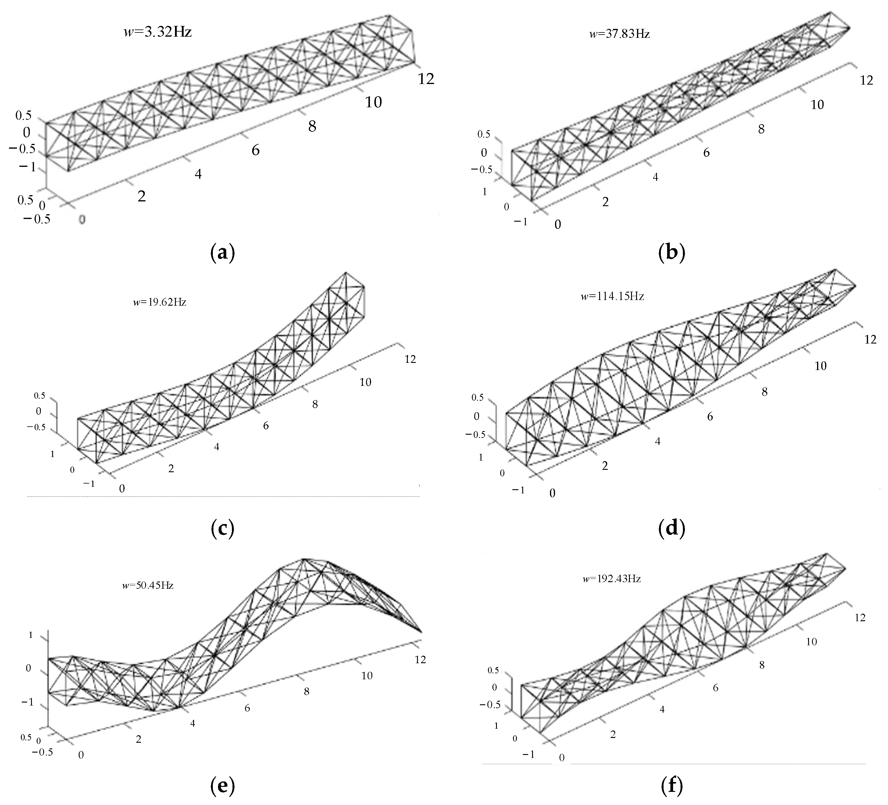
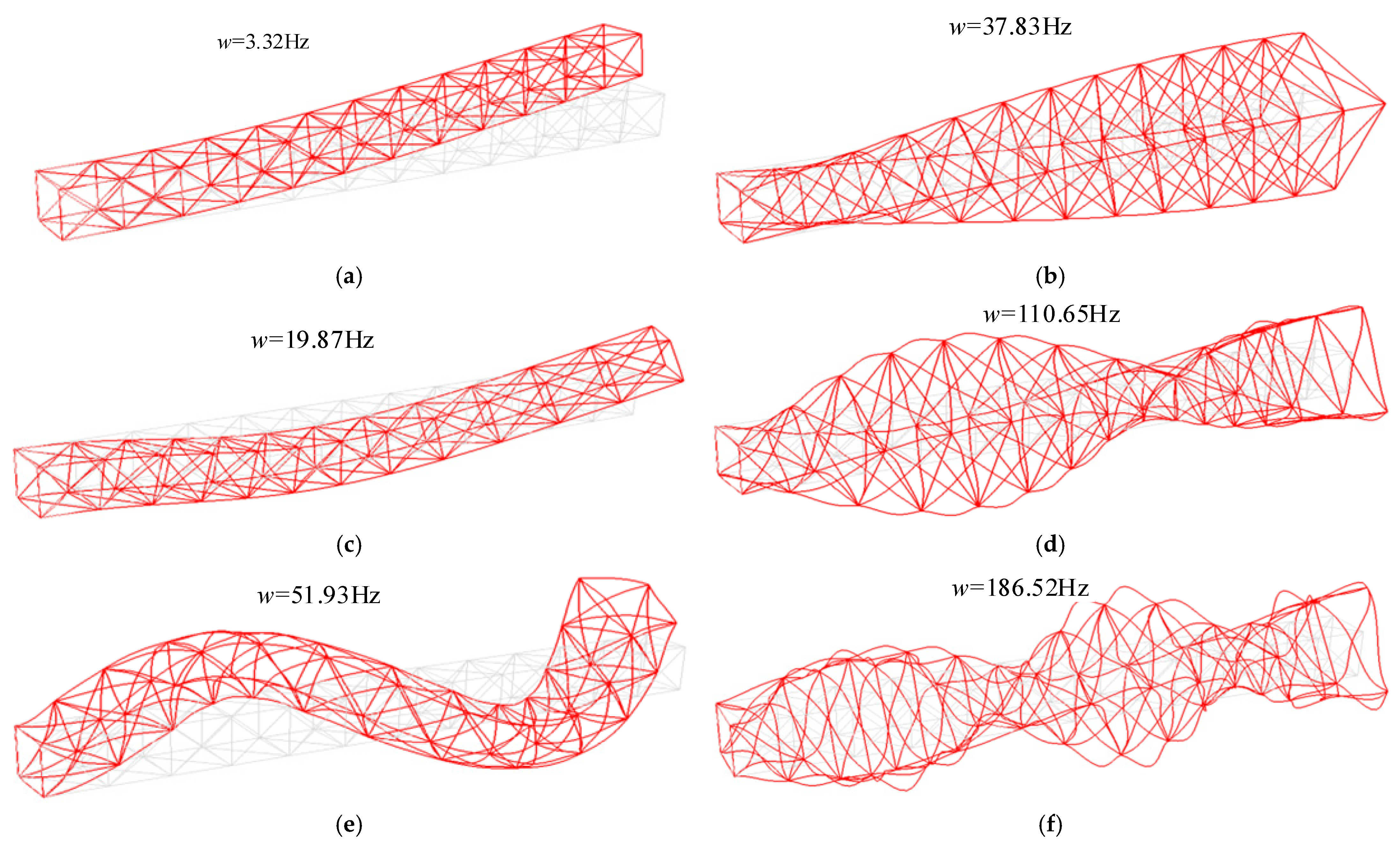
The equivalent elastic parameter of the modified flexible QTS equivalent beam model was used for modal analysis to verify the equivalent elastic parameter accuracy of the modified model. The equivalent beam was divided into 12 shear Timoshenko beam elements and modal analysis was performed using the Abaqus 2020 software. The modal mode and natural vibration frequency of each order were derived for the equivalent beam model. The results are compared with the actual QTS modal mode and corresponding vibration frequency, as shown in Figure 8 and Figure 9. The natural frequencies and relative error of the modified equivalent model are listed in Table 3.
The relative errors RE2 between the simulated QTS and the modified equivalent beam are no more than 4.7.%. The accuracy of the modified equivalent beam model is proven to be sufficient. The relative error increases with the increase in order. The stiffness parameters derived using the equivalent beam principle are written as follows:
E A = 27.34 × 10 8 , G J = 80.78 × 10 8 , E I z = 47.49 × 10 8 , E I y = 47.75 × 10 8

5. Conclusions

In this study, the space repetitive QTS is regarded as an equivalent beam model based on the energy equivalent method. The space QTS is equivalent to a slender Timoshenko beam based on the equivalent beam principle. According to the energy equivalence principle, the space equivalent beam elastic matrix and inertia matrix are calculated. With the whole dynamic model of the space in-orbit service simulation test platform established, the equivalent elastic parameter obtained can be directly applied to the dynamic equation of the system. The model is then corrected to improve the accuracy of the equivalent beam model. A thorough comparison of the equivalent beam model and the FE model is conducted for the vibration of the space QTS using a numerical example. The relative error between the finite element model and the corrected equivalent beam model of the column quadrilateral truss structure is no more than 4.7%. The results indicate that the accuracy of the modified equivalent beam model is sufficient.

Author Contributions

Methodology, B.L.; formal analysis, B.L.; investigation, Y.W.; writing—original draft preparation, Y.W. and H.Y.; writing—review and editing, B.L. and Y.L.; supervision, J.T.; funding acquisition, H.R. All authors have read and agreed to the published version of the manuscript.

Funding

This research was funded by the National Natural Science Foundation of China (Grants No. 52375028, 52105013, and 52192631) and by the Science and Technology Project of the Hebei Education Department (Grant No. QN2023206). The authors thank the anonymous reviewers for helping us to improve the quality of this article.

Data Availability Statement

All data are contained within the article.

Conflicts of Interest

The authors declare no conflicts of interest.

References

  1. Torabi, J.; Niiranen, J. Nonlinear finite element free and forced vibrations of cellular plates having lattice-type metamaterial cores: A strain gradient plate model approach. Mech. Syst. Signal Process. 2023, 192, 110224. [Google Scholar] [CrossRef]
  2. Arndt, M.; Machado, R.D.; Scremin, A. An adaptive generalized finite element method applied to free vibration analysis of straight bars and trusses. J. Sound Vib. 2010, 329, 659–672. [Google Scholar] [CrossRef]
  3. Chung, J.; Yoo, H.H. Dynamic analysis of a rotating cantilever beam by using the finite element method. J. Sound Vib. 2002, 249, 147–164. [Google Scholar] [CrossRef]
  4. Stoltani, Z.; Santer, M. The determination and enhancement of compliant modes for high-amplitude actuation in lattices. Int. J. Solids Struct. 2020, 206, 124–136. [Google Scholar] [CrossRef]
  5. Noor, A.K.; Nemeth, M.P. Analysis of spatial beam like lattices with rigid joints. Comput. Methods Appl. Mech. Eng. 1980, 24, 35–59. [Google Scholar] [CrossRef]
  6. Noor, A.K.; Nemeth, M.P. Micropolar beam models for lattice grids with rigid joints. Comput. Methods Appl. Mech. Eng. 1980, 21, 249–263. [Google Scholar] [CrossRef]
  7. Noor, A.K.; Anderson, M.S.; Greene, W.H. Continuum models for beam–and platelike lattice structures. AIAA J. 1978, 16, 1219–1228. [Google Scholar] [CrossRef]
  8. Penta, F.; Monaco, M.; Pucillo, G.P.; Gesualdo, A. Periodic beam–like structures homogenization by transfer matrix eigen–analysis: A direct approach. Mech. Res. Commun. 2017, 85, 81–88. [Google Scholar] [CrossRef]
  9. Weeger, O.; Boddeti, N.; Yeung, S.K.; Kaijima, S.; Dunn, M.L. Digital design and nonlinear simulation for additive manufacturing of soft lattice structures. Addit. Manuf. 2019, 25, 39–49. [Google Scholar] [CrossRef]
  10. Salehian, A.; Lbrahim, M.; Seigler, T.M. Damping in periodic structures: A continuum modeling approach. AIAA J. 2014, 52, 569–590. [Google Scholar] [CrossRef]
  11. Liu, F.; Wang, L.; Jin, D.; Liu, X.; Lu, P. Equivalent beam model for spatial repetitive lattice structures with hysteretic nonlinear joints. Int. J. Mech. Sci. 2021, 200, 106449. [Google Scholar] [CrossRef]
  12. Yildiz, K.; Lesieutre, G.A. Deployment of n-strut cylindrical tensegrity booms. J. Struct. Eng. 2020, 146, 04020247. [Google Scholar] [CrossRef]
  13. Koohestani, K. Novel topological and geometrical modeling of N-frequency geodesic icosahedron tensegrities. Eng. Comput. 2022, 38, 5733–5745. [Google Scholar] [CrossRef]
  14. Hrabacka, M.; Bulin, R.; Hajzman, M. New actuation planning method for the analysis and design of active tensegrity structures. Eng. Struct. 2023, 293, 116597. [Google Scholar] [CrossRef]
  15. Penta, F.; Esposito, F.; Pucillo, G.P.; Rosiello, V.; Gesualdo, A. On the homogenization of periodic beam-like structures. Procedia Struct. Integr. 2018, 8, 399–409. [Google Scholar] [CrossRef]
  16. Karttunen, A.T.; Reddy, J.N.; Romanoff, J. Two-scale constitutive modeling of a lattice core sandwich beam. Compos. Part B Eng. 2019, 160, 66–75. [Google Scholar] [CrossRef]
  17. Finozzi, A.; Sanfedino, F.; Alazard, D. Parametric sub-structuring models of large space truss structures for structure/control co-design. Mech. Syst. Signal Process. 2022, 180, 109427. [Google Scholar] [CrossRef]
  18. Sanfedino, F.; Alazard, D.; Pommier-Budinger, V.; Falcoz, A.; Boquet, F. Finite element based N-port model for preliminary design of multibody systems. J. Sound Vib. 2018, 415, 128–146. [Google Scholar] [CrossRef]
  19. Yang, H.; Feng, J.; Wang, Y.; Xiao, H.; Liu, Y.B. Equivalent dynamic model for large parabolic cylindrical deployable mechanism. AIAA J. 2022, 60, 6739–6752. [Google Scholar] [CrossRef]
  20. Zhang, G.W.; Liu, F.S. Equivalent dynamic modeling for the relative rotation of bolted joint interface using valanis model of hysteresis. Machines 2023, 11, 342. [Google Scholar] [CrossRef]
  21. Liu, F.S.; Wang, L.B.; Jin, D.P.; Liu, X.; Lu, P. Equivalent micropolar beam for spatial vibration analysis of planar repetitive truss structure with flexible joints. Int. J. Mech. Sci. 2020, 165, 105202. [Google Scholar] [CrossRef]
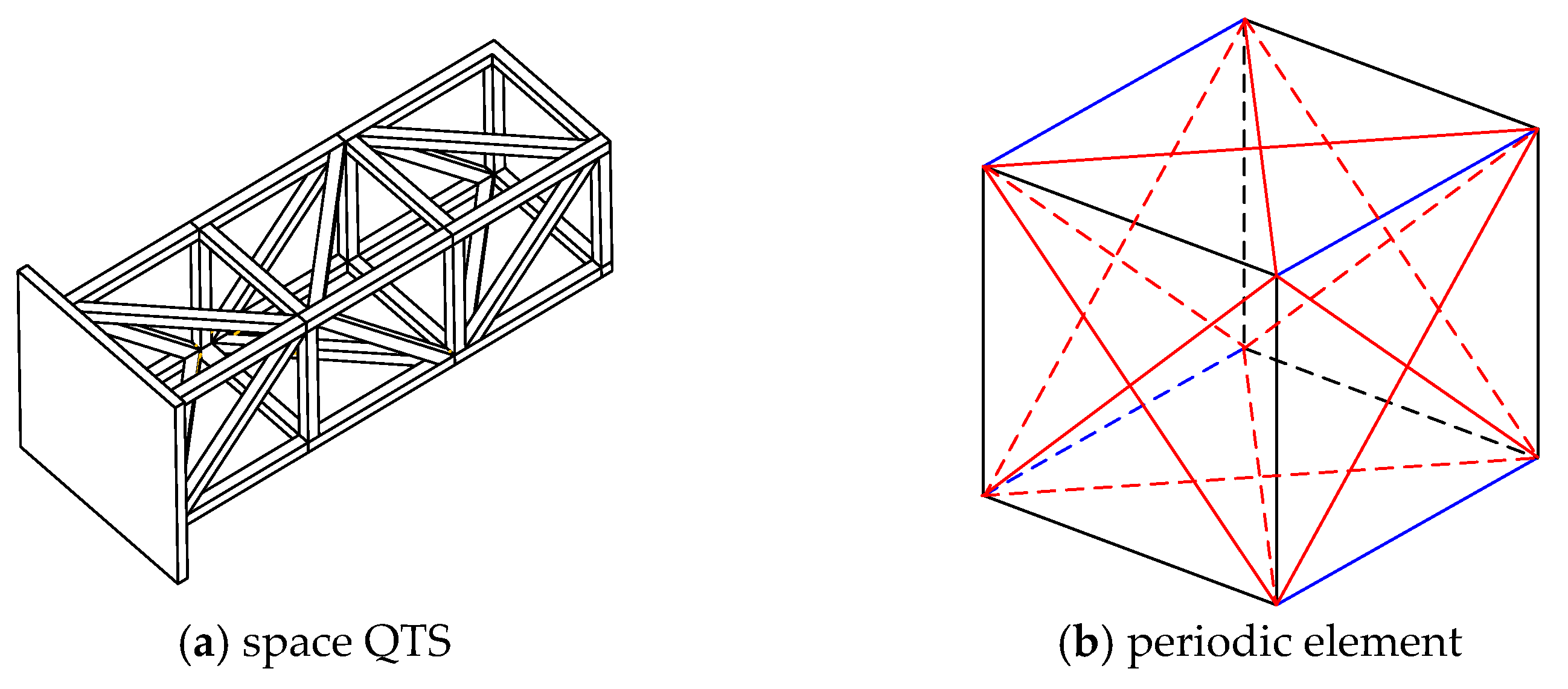
Figure 1. Space QTS and periodic element. The blue lines indicate the longitudinal beam, the black lines indicate the transversal beam, and the red line indicate the inclined beam.
Machines 12 00111 g001
Figure 2. Flowchart of the equivalent beam model.
Machines 12 00111 g002
Figure 3. Periodic and cross-section coordinate system. The blue lines indicate the longitudinal beam, the black lines indicate the transversal beam, and the red line indicate the inclined beam.
Machines 12 00111 g003
Figure 4. Periodic element and column QTS in the in-orbit space platform. The blue lines indicate the longitudinal beam, the black lines indicate the transversal beam, and the red line indicate the inclined bea.
Machines 12 00111 g004
Figure 5. Space beam element.
Machines 12 00111 g005
Figure 6. First six orders of the bending vibration mode of the equivalent beam: (a) first-order transverse bend mode, 3.77 Hz; (b) first-order vertical bend mode, 3.79 Hz; (c) second-order transverse bend mode, 22.20 Hz; (d) second-order vertical bend mode, 22.17 Hz; (e) third-order transverse bend mode, 57.35 Hz; (f) third-order vertical bend mode, 56.79 Hz.
Machines 12 00111 g006
Figure 7. Torsional mode and axial compression mode: (a) first-order torsional mode, 36.67 Hz; (b) second-order torsional mode, 110.65 Hz; (c) third-order torsional mode, 186.52 Hz; (d) first-order axial compression mode, 42.94 Hz.
Machines 12 00111 g007
Figure 8. First three orders of the bending and torsional modes of the modified equivalent beam: (a) first-order bend mode; (b) first−order torsional mode; (c) second-order bend mode; (d) second-order torsional mode; (e) third-order bend mode; (f) third-order torsional mode.
Machines 12 00111 g008
Figure 9. First three orders of the bending and torsional modes of the simulated QTS: (a) first-order bend mode; (b) first-order torsional mode; (c) second-order bend mode; (d) second-order torsional mode; (e) third-order bend mode; (f) third-order torsional mode.
Machines 12 00111 g009
Table 1. Material parameters of the component in the periodic element.
Material Parameter Value
Yong modulus E/Gpa207
Density ρ kg/m37830
Poisson’s ratio v0.3
Table 2. Natural frequencies and relative errors (REs) of the equivalent model.
ModeOrder Frequencies /HzRE1 %
The FE ModelThe Equivalent Beam Model
Transverse bend 13.313.7714.03
219.8722.1711.58
351.9356.799.37
Vertical bend13.313.7914.78%
219.8722.2011.73%
351.9357.3510.43%
Torsional 137.8336.673.06
2112.45110.651.60
3183.76186.521.50
Axial tension and compression 143.1342.940.43
Table 3. Natural frequencies and relative error of the modified equivalent model.
ModeOrderFrequency/HzRE1 %The Modified Equivalent Beam ModelRE2 %
The FE ModelThe Initial Equivalent Beam Model
Bend13.323.7714.033.320.32
219.8722.1711.5819.541.67
351.9356.799.3750.442.87
Twist137.8336.673.0637.830.01
2112.45110.651.60114.141.50
3183.76186.521.50192.404.70
Disclaimer/Publisher’s Note: The statements, opinions and data contained in all publications are solely those of the individual author(s) and contributor(s) and not of MDPI and/or the editor(s). MDPI and/or the editor(s) disclaim responsibility for any injury to people or property resulting from any ideas, methods, instructions or products referred to in the content.