1. Introduction
The exoskeleton can be defined as a mechatronic device that can be worn by a person and that, through the physical contact between the person and the device, ensures an exchange of mechanical power and information signals [
1,
2]. There are several categories of exoskeletons depending on the field in which they are used (industrial, military, medical) and for which part of the body they were created, generally either for the upper limbs or for the lower ones. This article is a study of exoskeletons designed for the upper limb, more precisely for the wrist joint, used in medicine in rehabilitation applications for patients who are in the recovery phase after suffering a stroke.
Stroke is defined by the Stroke Council of the American Heart Association/American Stroke Association as a transient episode of neurological dysfunction caused by focal brain, spinal cord, or retinal ischemia, without acute infarction [
3]. Stroke can be caused by many factors, disease processes, or pathological mechanisms. Most strokes are ischemic, generally caused by arteriolosclerosis of small vessels, cardio-embolism and arthero-thromboembolism of the large artery [
4].
Unfortunately, stroke is not a rare or isolated disease; according to the Global Burden of Disease, stroke is one of the most widespread diseases that lead to death or disability worldwide. Studies from 2019 show that over the course of 30 years, from 1990 to 2019, the number of deaths caused by strokes increased from 2.04 million to 3.29 million, and it is estimated that they will exceed 4.9 million by 2030 [
5,
6].
Stroke is also one of the most common causes of disability worldwide, especially in the case of the elderly, where the stroke rate is higher. Patients who survive a stroke are left with limb disabilities that prevent them from performing their daily activities or lose the mobility of their limbs, which significantly complicates their lives [
7].
Another important aspect of this state is the economic one. Currently, approximately 3 to 4% of total health care costs in Western countries are spent on stroke patients [
6]. These huge costs are mainly due to the therapy sessions performed by the patients during the recovery period. These therapies included various exercises and activities aimed at restoring strength, mobility, and muscle tone in the affected limbs. Therapies take place in hospitals or specialized centers under the permanent supervision of medical staff. Due to the need for permanent assistance, the cost of these therapies rises to the level of several billion dollars annually worldwide [
8,
9].
The use of exoskeleton devices in rehabilitation therapies is a reliable, convenient, and much cheaper alternative. The exoskeleton can reproduce the desired movements during the therapy sessions and can record and transmit in real time the data taken from the patient. This eliminates the need for permanent medical assistance as well as offering the possibility of holding sessions from the comfort of your own home. In this work, some of the prototypes of exoskeletons on the market are briefly presented.
2. Background
The interest in exoskeleton devices has grown a lot in recent years, mainly due to the many applications in which such devices can be used. Thus, there are numerous exoskeleton-type devices developed for the upper limb as well. They can be classified according to several criteria, such as the number of degrees of freedom (DOF), the articulation for which they were designed, the operating mode, their nature as active or passive devices, etc. [
10].
From the point of view of the actuation principle, most of the devices on the market are active exoskeletons, actuated with various motors or servomotors, but there are also devices actuated with the help of elastic elements. These devices are called passive exoskeletons because they are based on the force generated by the patient’s muscles. An example of such devices are SCRIPT passive orthosis (SPO) and SCRIPT SPO-F that use springs to transmit movement [
11,
12]. Other examples of passive devices are presented in [
13,
14].
In general, active devices with a single DOF generate the flexion–extension movement of the wrist, as is the case with the SCRIPT Active Orthosis Iteration 3 (SPO-I3) exoskeleton, which is operated by a direct current motor [
15]. Devices with a single DOF are presented in [
16,
17], where the movement is generated by a brushless electric motor, respectively, by a DC motor. In [
18] a 3D-printed single DOF device is presented that uses servomotors to generate the force necessary to perform the flexion/extension movement. Devices with a single DOF actuated by DC motors are also the two versions from eWrist presented in [
19,
20] that use the Myo armband equipped with electromyographic sensors [
21]. Other wrist flexion/extension devices are presented in [
22,
23], which use artificial pneumatic muscles to generate movement.
Devices with two DOF, both for flexion/extension and for abduction/adduction, are presented in [
24,
25,
26], where the movement is generated by a geared motor, linear actuators, and electric motors, respectively. Two low-cost devices using electromyographic sensors are presented in [
27,
28]. They have several DOFs and use electric motors to generate movement. A two-DOF device weighing approximately 140 g is presented in [
29]. It is powered by soft and flexible carbon fiber-based twisted and coiled artificial muscles (TCAMs).
Devices that use artificial pneumatic muscles (PMA) to generate the movement necessary to achieve the two movements of the wrist are presented in [
30,
31]. They are characterized by low weight and increased comfort in use by the patient.
Two devices that have a parallel mechanism are presented in [
32,
33]. In [
32], the device has two DOF and uses pneumatic actuators to generate the movement, respectively. In [
33], a device with 3 DOF is presented, which is characterized by simple kinematics and force control due to the use of the parallel mechanism.
Other examples of devices that have a parallel manipulator are presented in [
34,
35]. In [
34] the device has a spherical manipulator and can generate a full range of motions for abduction/adduction movements with limitations for flexion/extension movements, and in [
35] the device revolves around the human hand and fulfills the desired workspace specifications for certain wrist joint motions.
In [
36,
37,
38], devices with 3 DOF are presented. These devices, in addition to the two movements of the wrist, can also generate the pronation/supination movement of the forearm.
3. Structural Analysis
The proposed parallel manipulator should connect the forearm with the hand and allow 2 DoF equivalent to the motions of the wrist joint; that means the two orientation motions: pitch (flexion–extension) and yaw (adduction–abduction). From the structural point of view, the parallel manipulator consists of a fixed element and a mobile element connected with a universal joint with 2 DoF, respectively two kinematic chains that connect them, presented in
Figure 1.
For the mechanisms with independent closed multi-loops, the number of independent closed loops
results from the relationship proposed by Hochman in [
39]:
where
—total number of joints and
—total number of elements.
Next, the degree of mobility
will be computed by using the extended Chebychev–Grübler–Kutzbach’s mobility criterion [
40]:
where
is the mobility of the i-th elementary closed loop:
where
—the degree of mobility of the
j-th joint,
—the motion parameter of the i-th elementary closed loop, and
is the mobility of the common joints between different closed loops,
By considering the structural schema from
Figure 1b, we can see the mobilities of the independent closed loops
and
and the mobility of the common joint:
the mobility degree of the parallel manipulator results:
In order to find out all the structures of the parallel manipulator with 2 DoF with the structural schema given in
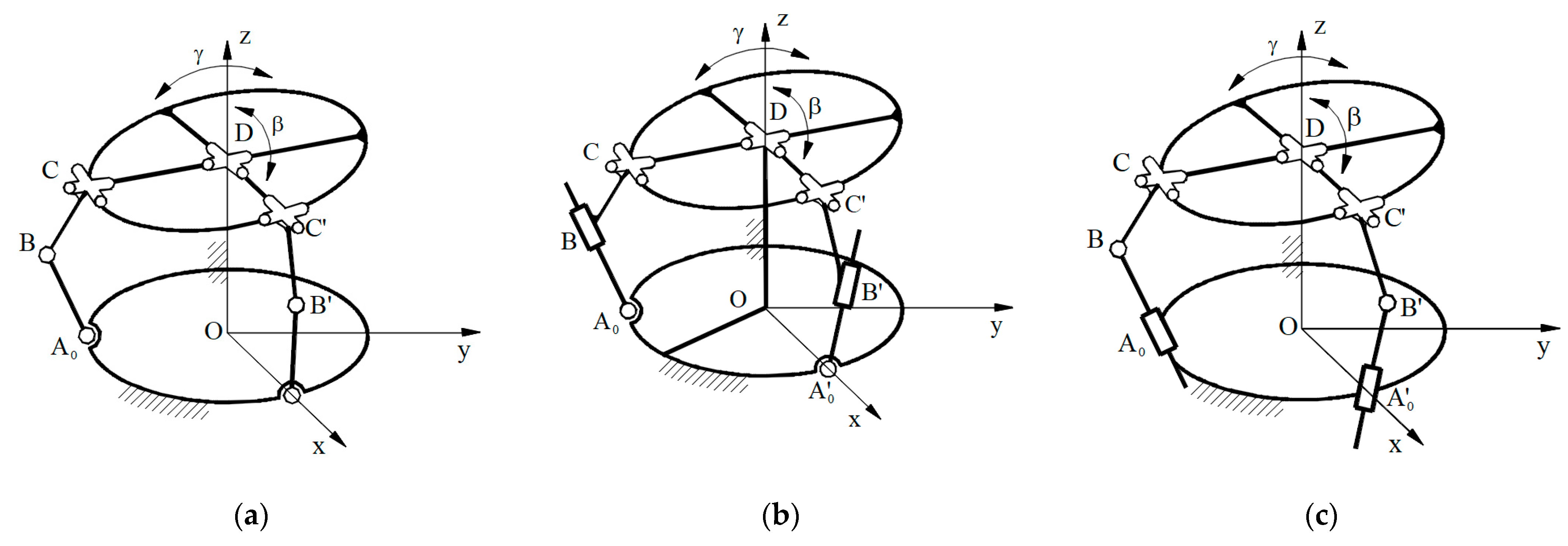
Figure 1b, it is necessary to develop all the combinations of the connection legs containing 2 elements, 2 joints with
, and 1 joint with
, usually a universal joint (see
Figure 2a–c).
The useful parallel manipulator structures resulted are as follows: 2-RRU-U, 2-RTU-U, and 2-TRU-U (see
Figure 2a–c). The structure 2-TTU-U was considered not useful.
4. Kinematic Analysis
The kinematic schema of the parallel manipulator 2-RRU-U is shown in
Figure 3a [
41]. It consists of a fixed element, a mobile element connected with a universal joint with the first one, as well as the two legs of type RRU. The legs of the parallel manipulator work in perpendicular planes, as can be seen in
Figure 3a and D, is the wrist articulation with 2 DoF.
Figure 3b,c [
41] show the equivalent four-bar linkages in the planes xOz for the pitch motion and yOz for the yaw motion.
The closed-loop equation written in complex numbers for the first four-bar linkage OA’
0B’C’D (see
Figure 3b) and the second four-bar linkage (see
Figure 3c) OA
0BCD are as follows [
41]:
where
and
are the drive angle, respectively, and
and
are the driven angles for the pitch and yaw motions.
By multiplying the complex number Equations (7) and (8) with their conjugate complex number equations, the transmission functions result:
From the Equation (9) can be computed the transmission function of the linkages as follows:
where [
39]
5. Optimal Synthesis
The main task of the proposed synthesis method is to avoid the singular positions of the links, which occur when the neighboring links are in extended or superposed position. The optimization of the synthesis considers as optimization parameters the minimum input transmission angle and the total size of the synthetized four-bar linkage. The scope is to have a higher value for the minimum input transmission angle and a lower value for the total size area.
The necessary conditions to achieve the minimum and maximum positions of the point M for the synthesized four-bar linkage can be written as (see
Figure 4a,b):
where:
For an analytical solution of the synthesis method, it is necessary to transform the previous inequations into an equation system by considering a supraunitary coefficient
multiplied to the lower term of the inequation. By multiplying the lower term of the Equations (13) and (14) with a supraunitary coefficient
, they are transformed into an equation system, as follows:
The equation system allows the computation of the link lengths of the four-bar linkage in the form:
Because the values of the link lengths depend on the supraunitary coefficient
, it is recommended to follow an optimal synthesis to compute the optimal value of the coefficient
. As previously presented, the target functions should maximize the parameters value of the minimum transmission angles
and minimize the total size
for each mechanism. For those conditions, the target functions are given as follows:
where
and
are the weight coefficients of optimization parameters, respectively the indices of the parameters and the target functions refer to the pitch (
and yaw (
motions.
with the minimum input transmission angles given through the relationships:
and accordingly, the total size of the acting mechanisms:
where
6. Design and Prototype of the Wrist Exoskeleton
The input design parameters of the parallel manipulator 2-RRU-U used for the wrist exoskeleton are given in
Table 1, and they are close to the human hand and forearm dimensions [
42]. The orientation angle of the mobile platform rigidized with the hand should realize the pitch (flexion–extension) motion in the range of
and yaw (adduction–abduction) motion in the range of
. These values are higher as the functional motion range for activities of daily living indicated in [
42].
In the following, it will be shown in
Table 2 and
Table 3 the optimal synthesis results by considering as optimization parameters only the minimum input transmission angle, only the total size of the synthetized four-bar linkage, and as target functions, by considering both parameters weighted with coefficients
.
The maximum value of the minimum input transmission angle results for the supraunitary coefficient
in case of the pitch motion and
in the case of the yaw motion, as it is shown in
Figure 5.
The minimum total size of the synthesized four-bar linkage comes out for both four-bar linkages for the supraunitary coefficient
, because the functions
and
are monotone increasing functions, as it is shown in
Figure 6.
The minimum target function results for the same supraunitary coefficient
, as it is shown in
Figure 7a for the pitch and
Figure 7b for the yaw motion. In the same figures are represented near the target function the normalized input minimum transmission angles and normalized total size of the four-bar linkages separately for the pitch and yaw motion. Because in the case of the optimization parameter minimum input transmission angle it was looking for the maximum value, and in the case of the optimization parameter total size of the four-bar linkage for the minimum value, the second optimization parameter has the sign minus. That means the optimum value for the target function should be the maximum value. The minimum input transmission angle for the optimized four-bar linkages is very close to the maximum value of theirs, but the total size of the four-bar linkage is meaningfully higher than the absolute minimum total size.
Figure 8a,b shows on scale the two four-bar linkages used for acting the wrist exoskeleton.
The 3D model of the proposed prototype for an exoskeleton device for wrist rehabilitation applications is shown in
Figure 9. The 3D model it is composed of the following elements: the support for the hand (a), the bracelet for the wrist joint which is also considered the mobile element (b), the arm which is mounted on the forearm and is considered a fixed element (c), two servomotors for transmitting the movement, one for flexion–extension movement (d), and one for abduction–adduction movement (e), supports for servomotors (f, g), two articulated bars (h, i), which are articulated at one end by the pinion of the servomotors and at the other end by the mobile element; these are responsible for transmitting the movement from the servomotors and the fixing holes (j) on the fixed and the mobile arm that have the role of attaching the device to the patient’s limb with the help of elastic bands.
Figure 10a,b show the proposed prototype for the pitch motion in the maximum flexed and maximum extended positions, respectively.
Figure 11a,b show the prototype for the yaw motion in the maximum abducted and maximum adducted positions.
7. Performance Analysis of the Optimized Parallel Manipulator 2-RRU-U
The Jacobian matrix must be determined to compute the previously mentioned performance indices. This is how the Jacobian matrix is calculated [
43,
44,
45]:
where
and
are as follows:
where the transmission functions
and
are computed according to Equations (9), (11), and (12).
The values of the partial derivatives are as follows:
The first measures that were determined to investigate the presence of singularities in the reachable workspace are for the type I and type II singularities. The type I singularities are described by positions inside of the reachable workspace in which the determinant of the matrix is zero, and type II singularities are described by positions inside of the reachable workspace in which the determinant of the matrix is zero.
The analytic expressions describing the determinants of the
and
matrices are as follows:
The analytical conditions for which the manipulator presents type I singularities are as follows:
The analytical conditions for which the manipulator presents type II singularities are as follows:
The geometrical conditions for which the manipulator presents type I singularities are described by positions inside the reachable workspace in which the moving links and , respectively, and the moving links and present collinearity. The geometrical conditions for which the manipulator presents type II singularities are described by positions inside the reachable workspace in which the moving links and , respectively, and the moving links and present collinearity.
The distributions for the determinants of the matrices and are presented in the following figures.
From
Figure 12 and
Figure 13, it can be observed that the synthesized manipulator using
and
presents type I singularities on the borders of the reachable workspace. Also, it can be observed that the synthesized manipulators using
,
and using
,
lack type I or type II singularities inside the reachable workspace since the values of the determinants of the
and
matrices have nonzero values.
In the following are shown the corresponding manipulability indices, condition number indices, and stiffness indices for the synthetized 2-RRU-U parallel manipulator.
7.1. Manipulability Index for the Optimized 2-RRU-U Parallel Manipulator
Yoshikawa was the first to introduce the manipulability index (
µ), which measures a structure’s capacity to move in any direction inside the workspace and is calculated as follows [
46].
The following distributions for the manipulability index were achieved for the previously presented numerical examples:
It can be observed from
Figure 14 that the manipulator synthesized using
,
has a singular configuration since the positions
,
,
, and
are inside the reachable workspace. Furthermore, it can be observed that the manipulators synthesized using
,
, respectively, and
,
, have a singularity-free workspace, and the following maximal, minimal, and mean values for the manipulability index are shown in the following table.
Based on the results from
Table 4 and the distributions from
Figure 12, it can be observed that the manipulator synthesized using
and
, has greater minimal, maximal, and global values for the manipulability, thus, the manipulator synthesized for achieving maximal minimum transmission angle is the manipulator considered to have the best maneuverability out of the three analyzed manipulators. Furthermore, the manipulator synthesized using
and
.
7.2. Condition Number Index for the Optimized 2-RRU-U Parallel Manipulator
The dexterity of the structure is directly related to the Condition Number Index (K). The ratio between the maximal and smallest values of the singular values of the Jacobian is how the Condition Number Index is calculated [
47,
48].
The following distributions for the Condition Number index were achieved for the previously presented numerical examples.
It can be observed from
Figure 15 that the manipulator synthesized using
,
has configurations with no dexterity, signifying that the manipulator lacks the ability to exert forces and move uniformly in any direction of the workspace, caused by the presence of the previously stated points in which the manipulator has singular configurations. Furthermore, it can be observed that the manipulators synthesized using
,
, respectively,
,
, have dexterous workspaces, meaning workspaces lacking configurations with no dexterity, and the following maximal, minimal, and mean values for the condition number are shown in the following table.
The absence of a mean value for the condition number measure of the manipulator synthesized using the values and is caused by the fact that when the manipulator approaches a singular configuration, the Jacobian loses its full rank, resulting in being zero, thus resulting in the value of the condition number index approaching infinity.
Based on the results from
Table 5 and the distributions from
Figure 13, it can be observed that the manipulator synthesized using
,
, has lower maximum and global values for the condition number; hence, it is a more dexterous manipulator, being able to exert higher forces and move more uniformly in all directions of the reachable workspace than the other compared manipulators.
7.3. Local Stiffness Index for the Optimized 2-RRU-U Parallel Manipulator
The Local Stiffness Index (LSI), which is defined as the ratio of the minimal and maximal values of the singular values of the Stiffness matrix [
49], a matrix characterized as the product between the transposed Jacobian and the Jacobian [
49], is calculated similarly to the Condition Number Index [
48].
The product between the transposed Jacobian matrix and the Jacobian matrix will lead to achieving singular values whose values are the square of the singular values obtained as in the case of the condition number; the resulting values of the Local Stiffness Index are the square of the reciprocal values of the condition number index for each point inside the reachable workspace.
By considering the previously stated points, it can also be observed from
Figure 15 that the manipulator synthesized by using
,
has configurations with values for the Local Stiffness Index approaching zero (regions in which the value of the condition number is approaching infinity), thus having configurations in which the manipulator is not able to resist external disturbances and maintain accuracy under load, while the other synthesized manipulators have workspaces with values for the Local Stiffness Index higher than zero.
8. Conclusions
This paper proposes an optimized parallel manipulator prototype that can be a suitable candidate for an exoskeleton-type wrist rehabilitation device. For this aim, a structural analysis was developed from which we find out the degree of freedom DoF = 2 of the useful structures for the parallel manipulator, which are of type 2-RRU-U, 2-RTU-U, and 2-TRU-U.
Further, the study was concentrated on developing the kinematic analysis and optimal synthesis of the parallel manipulator 2-RRU-U.
From the previously performed results, it can be concluded that the optimal synthesis method for determining the optimal link lengths of the 2-RRU-U parallel manipulator, based on a minimal manipulator boundary and maximal minimum transmission angle, was achieved.
Furthermore, the resulting optimal link lengths for the 2-RRU-U parallel manipulator led to achieving a manipulator with a singularity-free, dexterous workspace. It was observed that the manipulator achieved using the optimal synthesis method has increased manipulability, dexterity, and stiffness compared to the manipulator that would achieve minimal boundary workspace but decreased kinematic performance compared to the manipulator achieving maximal minimum transmission angle.
This prototype has the advantage of being suitable for both types of wrist movements in a range of motion very close to that of the human hand. This aspect is influenced by many factors, including the limitations of the servomotors and the design of the connecting elements between the fixed and mobile bracelet.
Further research is proposed to investigate and observe the results of applying the synthesis method on linkages and serial structures with a higher degree of freedom. Also, further research is proposed to investigate the effects on the “k” term, used in computing the link lengths, if maximizing or minimizing performance indices is used as scope functions in addition to maximizing the minimum transmission angle and minimizing the workspace boundary of the synthesized structure. An interesting further subject is to compare the kinematic performance measures to other counterparts and compare theoretical and real performance measures.
Regarding the prototype’s usability, comfort, and effectiveness, it will be evaluated by a physiotherapist, and the results will be the subject of future studies.
Author Contributions
Conceptualization, E.-C.L. and N.-G.C.; methodology, E.-C.L., N.-G.C., E.-G.T. and A.O.; software, A.O., N.-G.C. and C.C.; validation, E.-C.L. and E.-G.T.; formal analysis, E.-C.L. and A.O.; investigation, N.-G.C. and C.C.; resources, A.O.; data curation, N.-G.C., A.O. and C.C.; writing—original draft preparation, E.-C.L., A.O. and E.-G.T.; writing—review and editing, E.-C.L., N.-G.C., A.O. and E.-G.T.; visualization, A.O., N.-G.C. and C.C.; supervision, E.-C.L. and N.-G.C. All authors have read and agreed to the published version of the manuscript.
Funding
This research received no external funding.
Data Availability Statement
Data are contained within the article.
Conflicts of Interest
The authors declare no conflicts of interest.
References
- Spada, S.; Ghibaudo, L.; Gilotta, S.; Gastaldi, L.; Cavatorta, M.P. Analysis of Exoskeleton Introduction in Industrial Reality: Main Issues and EAWS Risk Assessment. In Proceedings of the International Conference on Applied Human Factors and Ergonomics, Orlando, FL, USA, 21–25 July 2018. [Google Scholar]
- Olar, M.L.; Leba, M.; Risteiu, M. Exoskeleton-wearable devices. Literature review. MATEC Web Conf. 2021, 342, 05005. [Google Scholar] [CrossRef]
- Easton, J.D.; Saver, J.L.; Albers, G.W.; Alberts, M.J.; Chaturvedi, S.; Feldmann, E.; Hatsukami, T.S.; Higashida, R.T.; Johnston, S.C.; Kidwell, C.S. Definition and evaluation of transient ischemic attack: A scientific statement for healthcare professionals from the American Heart Association/American Stroke Association Stroke Council; Council on Cardiovascular Surgery and Anesthesia; Council on Cardiovascular Radiology and Intervention; Council on Cardiovascular Nursing and the Interdisciplinary Council on Peripheral Vascular Disease. Stroke 2009, 40, 2276–2293. [Google Scholar] [PubMed]
- Murphy, S.J.; Werring, D.J. Stroke: Causes and clinical features. Medicine 2020, 48, 561–566. [Google Scholar] [CrossRef] [PubMed]
- Fan, J.; Li, X.; Yu, X.; Liu, Z.; Jiang, Y.; Fang, Y.; Zong, M.; Suo, C.; Man, Q.; Xiong, L. Global Burden, Risk Factor Analysis, and Prediction Study of Ischemic Stroke, 1990–2030. Neurology 2023, 101, 137–150. [Google Scholar] [CrossRef]
- Kalache, A.; Aboderin, I. Stroke: The global burden. Health Policy Plan. 1995, 10, 1–21. [Google Scholar] [CrossRef]
- Devereux, N.; Berns, A.M. Evaluation & Treatment of Psychological Effects of Stroke. Del. J. Public Health 2023, 9, 62–69. [Google Scholar]
- Ivey, F.M.; Hafer-Macko, C.E.; Macko, R.F. Exercise rehabilitation after stroke. NeuroRX 2006, 3, 439–450. [Google Scholar] [CrossRef]
- Tilling, K.; Sterne, J.A.C.; Rudd, A.G.; Glass, T.A.; Wityk, R.J.; Wolfe, C.D. A New Method for Predicting Recovery After Stroke. Stroke 2001, 32, 2867–2873. [Google Scholar] [CrossRef]
- Gull, M.A.; Bai, S.; Bak, T. A Review on Design of Upper Limb Exoskeletons. Robotics 2020, 9, 16. [Google Scholar] [CrossRef]
- Ates, S.; Lobo-Prat, J.; Lammertse, P.; van der Koji, H.; Stenen, A.H.A. SCRIPT Passive Orthosis: Design and Technical Evaluation of the Wrist and Hand Orthosis for Rehabilitation Training at Home. In Proceedings of the IEEE International Conference on Rehabilitation Robotics, Seattle, WA, USA, 24–26 June 2013. [Google Scholar]
- Ates, S.; Haarman, C.J.; Stienen, A.H. SCRIPT passive orthosis: Design of interactive hand and wrist exoskeleton for rehabilitation at home after stroke. Auton. Robot. 2017, 41, 711–723. [Google Scholar] [CrossRef]
- Gopura, R.A.R.C.; Bandara, D.S.V.; Kiguchi, K.; Mann, G.K.I. Developments in hardware systems of active upper-limb exoskeleton robots: A review. Robot. Auton. Syst. 2016, 75, 203–220. [Google Scholar] [CrossRef]
- Hussain, S.; Jamwal, P.K.; Van Vliet, P.; Ghayesh, M.H. State-of-The-Art Robotic Devices for Wrist Rehabilitation: Design and Control Aspects. IEEE Trans. Hum. Mach. Syst. 2020, 50, 361–372. [Google Scholar] [CrossRef]
- Ates, S.; Mora-Moreno, I.; Wessels, M.; Stienen, A.H.A. Combined Active Wrist and Hand Orthosis for Home Use: Lessons Learned. In Proceedings of the 2015 IEEE International Conference on Rehabilitation Robotics (ICORR), Singapore, 11–14 August 2015; Volume 2, pp. 227–241. [Google Scholar]
- Song, Z.; Guo, S. Design Process of Exoskeleton Rehabilitation Device and Implementation of Bilateral Upper Limb Motor Movement. J. Med. Biol. Eng. 2011, 32, 323–330. [Google Scholar] [CrossRef]
- Nam, H.S.; Koh, S.; Kim, Y.J.; Beom, J.; Lee, W.H.; Lee, S.U.; Kim, S. Biomechanical Reactions of Exoskeleton Neurorehabilitation Robots in Spastic Elbows and Wrists. IEEE Trans. Neural Syst. Rehabil. Eng. 2017, 25, 2196–2203. [Google Scholar] [CrossRef]
- Sarmiento-Ramos, J.L.; Anaya-Rojas, M.F. Modelling, design, and construction of a wrist rehabilitation exoskeleton. Sci. Tech. 2022, 27, 177–185. [Google Scholar] [CrossRef]
- Lambelet, C.; Lyu, M.; Wenderoth, N.; Woolley, D.; Gassert, R. The eWrist–A wearable wrist exoskeleton with sEMG-based force control for stroke rehabilitation. In Proceedings of the IEEE International Conference on Rehabilitation Robotics, London, UK, 17–20 July 2017; pp. 726–733. [Google Scholar]
- Lambelet, C.; Temiraliuly, D.; Siegenthaler, M.; Wirth, M.; Woolley, D.G.; Lambercy, O.; Gassert, R.; Wenderoth, N. Characterization and wearability evaluation of a fully portable wrist exoskeleton for unsupervised training after stroke. J. Neuroeng. Rehabil. 2020, 17, 132. [Google Scholar] [CrossRef]
- Visconti, P.; Gaetani, F.; Zappatore, G.; Primiceri, P. Technical Features and Functionalities of Myo Armband: An Overview on Related Literature and Advanced Applications of Myoelectric Armbands Mainly Focused on Arm Prostheses. Int. J. Smart Sens. Intell. Syst. 2018, 11, 1–25. [Google Scholar] [CrossRef]
- Meng, W.; Sheng, B.; Klinger, M.; Liu, Q.; Zhou, Z.; Xie, S.Q. Design and control of a robotic wrist orthosis for joint rehabilitation. In Proceedings of the IEEE/ASME (AIM) International Conference on Advanced Intelligent Mechatronics, Busan, Republic of Korea, 7–11 July 2015. [Google Scholar]
- Zhao, Y.; Qian, K.; Bo, S.; Zhang, Z.; Li, Z.; Li, G.Q.; Dehghani-Sanij, A.A.; Xie, S.Q. Adaptive Cooperative Control Strategy for a Wrist Exoskeleton Using Model-Based Joint Impedance Estimation. In Proceedings of the IEEE/ASME Transactions on Mechatronics, Seattle, WA, USA, 27 June–1 July 2023. [Google Scholar]
- Xiao, Z.G.; Menon, C. Towards the development of a portable wrist exoskeleton. In Proceedings of the IEEE International Conference on Robotics and Biomimetics, Kanon Beach, Thailand, 7–11 December 2011. [Google Scholar]
- Higuma, T.; Kiguchi, K.; Arata, J. Low-Profile Two-Degree-of-Freedom Wrist Exoskeleton Device Using Multiple Spring Blades. In Proceedings of the IEEE Robotics and Automation Letters, Brisbane, Australia, 21–25 May 2018. [Google Scholar]
- Dragusanu, M.; Baldi, T.L.; Iqbal, Z.; Prattichizzo, D.; Malvezzi, M. Design, Development, and Control of a Tendon-actuated Exoskeleton for Wrist Rehabilitation and Training. In Proceedings of the IEEE International Conference on Robotics and Automation, Paris, France, 31 May–30 August 2020. [Google Scholar]
- Li, N.; Yang, T.; Yang, Y.; Yu, P.; Xue, X.; Zhao, X.; Song, G.; Elhajj, I.H.; Wang, W.; Xi, N.; et al. Bioinspired Musculoskeletal Model-based Soft Wrist Exoskeleton for Stroke Rehabilitation. J. Bionic Eng. 2020, 17, 1163–1174. [Google Scholar] [CrossRef]
- Yang, S.; Li, M.; Wang, J.; Shi, Z.; He, B.; Xie, J.; Xu, G. A low-cost and portable wrist exoskeleton using EEG-sEMG combined strategy for prolonged active rehabilitation. Front. Neurorobot. 2023, 17, 1662. [Google Scholar] [CrossRef]
- Greco, C.; Weerakkody, T.H.; Cichella, V.; Pagnotta, L.; Lamuta, C. Lightweight Bioinspired Exoskeleton for Wrist Rehabilitation Powered by Twisted and Coiled Artificial Muscles. Robotics 2023, 12, 27. [Google Scholar] [CrossRef]
- AndriKopoulos, G.; Nikolakopoulos, G.; Manesis, S. Motion Control of a Novel Robotic Wrist Exoskeleton via Pneumatic Muscle Actuators. In Proceedings of the 20th IEEE International Conference on Emerging Technologies and Factory Automation (ETFA), Luxemburg, 1–8 September 2015. [Google Scholar]
- Al-Fahaam, H.; Davis, S.; Nefti-Meziani, S. Wrist Rehabilitation Exoskeleton Robot based on Pneumatic Soft Actuators. In Proceedings of the International Conference for Students on Applied Engineering (ICSAE), Newcastle, UK, 20–21 October 2016. [Google Scholar]
- Zhang, L.; Li, J.; Cui, Y.; Dong, M.; Fang, B.; Zhang, P. Design and performance analysis of a parallel wrist rehabilitation robot (PWRR). Robot. Auton. Syst. 2020, 125, 103390. [Google Scholar] [CrossRef]
- Lee, J.; Kim, H.; Yang, W. Development of Wrist Interface Based on Fully Actuated Coaxial Spherical Parallel Mechanism for Force Interaction. Sensors 2021, 21, 8073. [Google Scholar] [CrossRef] [PubMed]
- Valayil, T.P.; Tanev, T.K. A 3UPS/S Spherical Parallel Manipulator Designed for Robot-Assisted Hand Rehabilitation after Stroke. Appl. Sci. 2024, 14, 4457. [Google Scholar] [CrossRef]
- Valayil, T.P.; Tanev, T.K. Design of a Parallel Wrist Exoskeleton for Rehabilitation Post-Stroke. In Proceedings of the 10th International Conference on Automation, Robotics and Applications (ICARA), Athens, Greece, 22–24 February 2024; pp. 240–245. [Google Scholar]
- Spencer, S.J.; Klein, J.; Minakata, K.; Le, V.; Bobrow, J.; Reinkensmeyer, D. A low-cost parallel robot and trajectory optimization method for wrist and forearm rehabilitation using the Wii. In Proceedings of the BIOROB, Scottsdale, AZ, USA, 19–22 October 2008. [Google Scholar]
- Shi, K.; Song, A.; Li, Y.; Li, H.; Chen, D.; Zhu, L. A Cable-Driven Three-DOF Wrist Rehabilitation Exoskeleton With Improved Performance. Front. Neurorobot. 2021, 15, 664062. [Google Scholar] [CrossRef]
- Pezent, E.; Rose, C.G.; Deshpande, A.D.; O’Malley, M.K. Design and characterization of the OpenWrist: A robotic wrist exoskeleton for coordinated hand-wrist rehabilitation. In Proceedings of the International Conference on Rehabilitation Robotics (ICORR), London, UK, 17–20 July 2017. [Google Scholar]
- Hochman, K.I. Kinematics of Machinery, Odesa. 1890. Available online: https://scholar.google.com/scholar?q=K.I.%20Hochman%2C%20Kinematics%20of%20machinery%20 (accessed on 18 December 2024).
- Gogu, G. Chebychev–Grübler–Kutzbach’s criterion for mobility calculation of multi-loop mechanisms revisited via theory of linear transformations. Eur. J. Mech. A Solids 2005, 24, 427–441. [Google Scholar] [CrossRef]
- Crăciun, N.G.; Tulcan, E.G.; Ciapa, C.; Lovasz, E.C. Wrist Exoskeleton actuated by a Parallel Manipulator. In IFToMM Symposium on Mechanism Design for Robotics; Springer: Berlin/Heidelberg, Germany, 2024; Volume 166, pp. 185–192. [Google Scholar]
- Eschweiler, J.; Li, J.; Quack, V.; Rath, B.; Baroncini, A.; Hildebrand, F.; Migliorini, F. Anatomy, Biomechanics, and Loads of the Wrist Joint. Life 2022, 12, 188. [Google Scholar] [CrossRef]
- Buium, F.; Duca, C.; Leonchi, D. Problems Regarding Singularities Analysis of a 3-RRR Parallel Mechanism. Appl. Mech. Mater. 2014, 658, 569–574. [Google Scholar]
- Buium, F.; Leonchi, D.; Doroftei, I. A Workspace Characterization of the 0/3/3R Parallel Mechanism. Appl. Mech. Mater. 2014, 658, 563–568. [Google Scholar] [CrossRef]
- Buium, F.; Duca, C.; Doroftei, I.; Leonchi, D. Graphical shapes of the 2nd type singularities of a 3-RRR planar mechanism. In IOP Conference Series: Materials Science and Engineering, Proceedings of the 7th International Conference on Advanced Concepts in Mechanical Engineering, Iasi, Romania, 9–10 June 2016; IOP Publishing: Philadelphia, PA, USA, 2016; Volume 147, p. 012085. [Google Scholar]
- Yoshikawa, T. Manipulability of robotic mechanisms. Int. J. Robot. Reseach 1985, 4, 3–9. [Google Scholar] [CrossRef]
- Patel, S.; Sobh, T. Manipulator Performance Measures—A Comprehensive Literature Survey. J. Intell. Robot. Syst. 2015, 77, 547–570. [Google Scholar] [CrossRef]
- Gosselin, C.; Angeles, J. A global performance index for the kinematic optimization of robotic manipulators. J. Mech. Des. 1991, 113, 220–226. [Google Scholar] [CrossRef]
- Liu, X.-J.; Jin, Z.-L.; Gao, F. Optimum design of 3-DOF spherical parallel manipulators with respect to the conditioning and stiffness indices. Mech. Mach. Theory 2000, 35, 1257–1267. [Google Scholar] [CrossRef]
Figure 1.
Parallel manipulator for acting the wrist exoskeleton joint. (a) Kinematic schema; (b) Structural schema.
Figure 1.
Parallel manipulator for acting the wrist exoskeleton joint. (a) Kinematic schema; (b) Structural schema.
Figure 2.
Parallel manipulator for acting the wrist exoskeleton joint. (a) Kinematic schema 2-RRU-U; (b) Kinematic schema 2-RTU-U; (c) Kinematic schema 2-TRU-U.
Figure 2.
Parallel manipulator for acting the wrist exoskeleton joint. (a) Kinematic schema 2-RRU-U; (b) Kinematic schema 2-RTU-U; (c) Kinematic schema 2-TRU-U.
Figure 3.
Kinematic scheme of the parallel manipulator 2-RRU-U. (
a) General kinematic schema; (
b) Kinematic schema of four-bar linkage for acting the pitch motion; (
c) Kinematic schema of four-bar linkage for acting the yaw motion [
41].
Figure 3.
Kinematic scheme of the parallel manipulator 2-RRU-U. (
a) General kinematic schema; (
b) Kinematic schema of four-bar linkage for acting the pitch motion; (
c) Kinematic schema of four-bar linkage for acting the yaw motion [
41].
Figure 4.
Optimal synthesis of the parallel manipulator 2-RRU-U. (a) Four-bar linkage for acting the pitch motion in extreme positions; (b) Four-bar linkage for acting the yaw motion in extreme positions.
Figure 4.
Optimal synthesis of the parallel manipulator 2-RRU-U. (a) Four-bar linkage for acting the pitch motion in extreme positions; (b) Four-bar linkage for acting the yaw motion in extreme positions.
Figure 5.
Variation of the minimum input transmission angle of the four-bar linkages for the pitch and yaw motion.
Figure 5.
Variation of the minimum input transmission angle of the four-bar linkages for the pitch and yaw motion.
Figure 6.
Variation of the total size of the synthetized four-bar linkage of the four-bar linkages for the pitch and yaw motion.
Figure 6.
Variation of the total size of the synthetized four-bar linkage of the four-bar linkages for the pitch and yaw motion.
Figure 7.
Variation of the target function , the normalized total size and the normalized minimum transmission angle . (a) In the case of the four-bar linkage for the pitch motion; (b) In the case of the four-bar linkage for the yaw motion.
Figure 7.
Variation of the target function , the normalized total size and the normalized minimum transmission angle . (a) In the case of the four-bar linkage for the pitch motion; (b) In the case of the four-bar linkage for the yaw motion.
Figure 8.
Synthetized four-bar linkages. (a) Four-bar linkage for the pitch motion; (b) Four-bar linkage for the yaw motion.
Figure 8.
Synthetized four-bar linkages. (a) Four-bar linkage for the pitch motion; (b) Four-bar linkage for the yaw motion.
Figure 9.
The 3D model of the proposed prototype for a wrist exoskeleton device.
Figure 9.
The 3D model of the proposed prototype for a wrist exoskeleton device.
Figure 10.
The prototype of the wrist exoskeleton for the pitch motion. (a) Maximum flexed position; (b) Maximum extended position.
Figure 10.
The prototype of the wrist exoskeleton for the pitch motion. (a) Maximum flexed position; (b) Maximum extended position.
Figure 11.
The prototype of the wrist exoskeleton for the yaw motion. (a) Maximum abducted position; (b) Maximum adducted position.
Figure 11.
The prototype of the wrist exoskeleton for the yaw motion. (a) Maximum abducted position; (b) Maximum adducted position.
Figure 12.
Distributions for the determinant of the matrix for the 2-RRU-U parallel manipulator synthesized using k values of the following: left , , center , , and right 8, .
Figure 12.
Distributions for the determinant of the matrix for the 2-RRU-U parallel manipulator synthesized using k values of the following: left , , center , , and right 8, .
Figure 13.
Distributions for determinant of the matrix for the 2-RRU-U parallel manipulator synthesized using k values of the following: left , , center , , right 8, and .
Figure 13.
Distributions for determinant of the matrix for the 2-RRU-U parallel manipulator synthesized using k values of the following: left , , center , , right 8, and .
Figure 14.
Manipulability distributions for the 2-RRU-U parallel manipulator synthesized using k values of: left , , center , , right 8, .
Figure 14.
Manipulability distributions for the 2-RRU-U parallel manipulator synthesized using k values of: left , , center , , right 8, .
Figure 15.
Condition number distributions for the 2-RRU-U parallel manipulator synthesized using k values of the following: left , , center , , right 8, .
Figure 15.
Condition number distributions for the 2-RRU-U parallel manipulator synthesized using k values of the following: left , , center , , right 8, .
Table 1.
Initial design parameters of the parallel manipulator.
Table 1.
Initial design parameters of the parallel manipulator.
| No | Design Parameter | Values |
|---|
| 1 | | |
| 2 | | |
| 3 | | |
Table 2.
Optimal design parameters of the synthetized parallel manipulator for pitch motion.
Table 2.
Optimal design parameters of the synthetized parallel manipulator for pitch motion.
| No | Design Parameter | Optimization Parameter |
|---|
| | | max. μ21p min | min. Stp | max. Fp |
|---|
| 1 | | | | |
| 2 | | | | |
| 3 | | | | |
| 4 | | | | |
Table 3.
Optimal design parameters of the synthetized parallel manipulator for yaw motion.
Table 3.
Optimal design parameters of the synthetized parallel manipulator for yaw motion.
| No | Design Parameter | Optimization Parameter |
|---|
| | | max. μ21y min | min. Sty | max. Fy |
|---|
| 1 | | | | |
| 2 | | | | |
| 3 | | | | |
| 4 | | | | |
Table 4.
Minimal, maximal, and mean values for the manipulability distributions.
Table 4.
Minimal, maximal, and mean values for the manipulability distributions.
k Values
[-] | Minimal Value
[-] | Maximal Value
[-] | Mean Value
[-] |
|---|
| , | | | |
| , | | | |
| 8, | | | |
Table 5.
Minimal, maximal, and mean values for the condition number distributions.
Table 5.
Minimal, maximal, and mean values for the condition number distributions.
k Values
[-] | Minimal Value
[-] | Maximal Value
[-] | Mean Value
[-] |
|---|
| , | | ∞ | |
| , | | | |
| 8, | | | |
| Disclaimer/Publisher’s Note: The statements, opinions and data contained in all publications are solely those of the individual author(s) and contributor(s) and not of MDPI and/or the editor(s). MDPI and/or the editor(s) disclaim responsibility for any injury to people or property resulting from any ideas, methods, instructions or products referred to in the content. |
© 2024 by the authors. Licensee MDPI, Basel, Switzerland. This article is an open access article distributed under the terms and conditions of the Creative Commons Attribution (CC BY) license (https://creativecommons.org/licenses/by/4.0/).

 ,
, 


