Article

Analysis of Energy Efficiency in Spur Gear Transmissions: Cycloidal Versus Involute Profiles

by
Joaquim Maria Veciana
1,
Pau Salvadó
1,
Pau Català
2,* and
Lluïsa Jordi
1
1
Department of Mechanical Engineering, Escola Tècnica Superior d’Enginyeria Industrial de Barcelona (ETSEIB), Universitat Politècnica de Catalunya, Av. Diagonal 647, 08028 Barcelona, Spain
2
Department of Mechanical Engineering, Escola Politècnica Superior d’Enginyeria de Manresa (EPSEM), Universitat Politècnica de Catalunya, Av. de les Bases de Manresa 61-73, 08242 Manresa, Spain
*
Author to whom correspondence should be addressed.
Machines 2024, 12(12), 943; https://doi.org/10.3390/machines12120943
Submission received: 13 November 2024 / Revised: 9 December 2024 / Accepted: 19 December 2024 / Published: 21 December 2024
(This article belongs to the Section Machine Design and Theory)

Abstract

:
The involute profile is used almost exclusively in the manufacturing of spur gears. Nevertheless, in machinery design, the evaluation of environmental factors, such as energy efficiency, has become increasingly important when choosing between feasible solutions. As a result, the study of alternative profiles is gaining interest. The key novelty of this study is the comparative analysis of involute and cycloidal gear profiles with respect to frictional power losses in the tooth contact, as well as their impact on energy efficiency in spur gear transmissions. The coefficient of friction is approximated using two widely applied analytical lubrication models: the elastohydrodynamic and mixed elastohydrodynamic, both of which provide enough accurate values with a reasonable amount of computation burden in comparison with numerical methods. An additional contribution of this study is a sensitivity assessment of the energy efficiency of the cycloidal profile with regard to the auxiliary centrode diameters. This allows for an understanding of the geometrical constraints of this profile, specifically the maximum pressure angle—which is related to the radial loads applied to the shaft—and the tooth height—which is related to the bending moment at the tooth root—and hence, setting the appropriate ones to be equivalent to the involute profile. For the comparative analysis, equivalent profiles are selected based on similar tooth bending moments and radial loads supported by the shaft. After determining the centrode diameters of the cycloidal profile, the efficiency of both gear profiles and their sensitivity to gear size and gear ratio are compared. This study concludes that, for both profiles and friction analytical models, efficiency improves with increasing gear sizes and gear ratios, eventually converging to a constant value. Furthermore, both cycloidal and involute profiles exhibit comparable performance in terms of energy efficiency across both lubrication analytical models.

1. Introduction

Gear transmissions are widely used in a variety of machines and mechanisms, including applications such as mobility, energy generation, and the manufacturing industry. Although individual pairs of spur or helical gears operate at high energy efficiency levels (typically around 95–99%), their widespread use means that even small improvements in gear performance could significantly help the industrial sector reduce energy waste and emissions. To address this, various studies have focused on improving the energy efficiency of gear transmissions at different stages of their life cycle, from the design phase [1,2] to the manufacturing phase [3], or by comparing them with other feasible mechanical transmissions to achieve highly efficient applications [4].
During operation, energy losses in gear transmissions can be categorized into tooth mesh friction (sliding and rolling), bearing friction, gear windage, and oil churning [5,6,7]. For low to medium pitch line velocities (less than 20 m/s), the energy dissipation from the sliding and rolling friction during tooth meshing becomes more significant in the overall system energy losses [8,9,10].
The involute profile is the most widely used gear profile for several reasons:
  • It produces fewer vibrations and maintains constant loads on axles because the normal force at the contact point has an invariant direction and is nearly constant in magnitude.
  • It has low sensitivity to slight variations in gear center distance.
  • It allows for the use of cutter tools (racks) with straight flanks.
  • By displacing the cutter tool, the bending strength at the tooth root is increased (bigger root thickness) and the center distance can be adjusted. However, it has the drawbacks of the tip thickness being weakened and the contact ratio being decreased.
Other gear profiles offer better mechanical properties in terms of tooth bending strength and surface durability (pitting). Kalay et al. [11] have investigated how tooth profiles affect impact loads on involute gears by conducting experimental tests on asymmetric involute teeth. Jia et al. [12] have introduced a design methodology for non-involute cylindrical gears based on a curved path of contact which improves load distribution and reduces stress on the tooth flanks compared to the involute profile. Liu et al. [13] have found that sliding velocity and relative tooth-profile curvature are two of the most influential parameters affecting load distribution along the profile and, consequently, its durability. They have explored a new design method aimed at achieving a constant relative curvature in spur gear profiles which reduces wear on tooth surfaces. Liu et al. [14] have also presented a model to analyze the dynamics of gear drives with a curved path of contact under a mixed elastohydrodynamic lubrication (MEHL) regime. This model addresses the challenge of studying gear drives where the direction of the normal load changes between tooth flanks along the path of contact. Ikejo [15] proposed two different non-involute tooth profiles—a composite involute–cycloid and a modified cycloid tooth profile—both of which offer greater bending strength and improved tooth surface durability. Peng et al. [16] introduced a novel arc-tooth-trace cycloid profile with lower contact and bending stresses than the involute profile. Novikov [17] developed a helical gear where the pairing teeth make contact through a point (ideally) instead of a line. The teeth profile is defined by the radii of circles having a minimum difference in curvature (convex–concave). Although it is not possible to manufacture spur gears with this profile, it has some advantages compared to the helical gears with an involute profile, such as lower contact stress, less friction losses, and less wear.
Regarding energy efficiency, multiple studies have investigated the involute profile for spur and helical gears. In the 1980s and 1990s, Andersson and Loewenthal [1,2,8] conducted several studies evaluating efficiency or power losses in spur gears. Marques et al. [18] also analyzed the contribution of friction effects to power loss in spur gears with an involute profile. Diez-Ibarbia et al. [19] examined the effect of tip relief on frictional losses. Yue et al. [20] have proposed a dynamic model that couples the effect of friction to evaluate gear-meshing power loss and have obtained results that are in better agreement with experimental tests on spur gears with involute profiles. Mughal et al. [21] have evaluated the efficiency and coefficient of friction by using a tribodynamic model for an involute teeth profile of spur gears used in electric vehicle powertrains. Liu et al. [22] have also used a tribodynamic approach to evaluate the mechanical efficiency of multi-tooth meshing and to compare the influence of the shapes of teeth; the comparison has been made between an involute profile and a non-involute profile designed for the authors with a constant relative curvature [13].
Compared to the involute profile, the cycloidal profile has the following advantages:
  • Higher tooth strength because the tooth has a wider root and is therefore easier to manufacture with casting techniques or when small gears are required.
  • Lower Hertzian contact stresses because the contact surfaces are a pair of convex–concave surfaces (epicycloid–hypocycloid), while the involute has convex–convex surfaces.
  • No possibility of tooth undercutting, allowing for a lower number of teeth than involute and, hence, higher gear ratios.
  • If the generating diameters are half of the pitch diameter, which is normal for cycloidal teeth, the hypocycloid becomes a straight line following the radial direction, making it easier to manufacture.
The main disadvantages of the cycloidal profile in comparison with the involute profile are:
  • The cutting tools (rack) for manufacturing the flanks are not as simple as in the involute profile (straight flanks).
  • It is more sensitive to the distance between gear centers, which implies higher costs to achieve manufacturing tolerances. An incorrect distance produces a non-constant gear ratio and, therefore, induced vibrations.
Most of the studies conducted with the cycloidal profile referred to these characteristics. Fang et al. [23] proposed a compensation method to reduce the alignment error in measuring cycloidal gear tooth flanks. Abdulkareem and Abdullah [24] have explored the cycloidal profile behavior to enhance spur gear strength by simulating bending stresses and offering recommendations for stress reduction. Hmoad et al. [25] have developed a FEM analysis to assess the strength of bevel gears with a cycloidal tooth profile while also providing design recommendations. Nevertheless, there are no reported studies that address the energy performance of the cycloidal tooth profile for gear transmissions. For cycloidal reducers, also named cycloidal gearboxes, there are several recent works dealing with energy efficiency [26,27,28,29]. However, cycloidal reducers use a different cycloidal profile for the gear, where the teeth are in contact with rollers and not with other gear teeth.
In gear transmissions, the model most frequently used to characterize the friction between profiles is the sliding contact model based on the Coulomb model. This model defines the coefficient of friction, µ, as the quotient between the tangential force (frictional force) and the normal reaction force.
To determine μ, four primary analytical strategies are noted in the literature dealing with gear tooth contact:
  • A constant coefficient of friction along the contact surface deduced experimentally (for all lubrication regimes [10] and for boundary and mixed conditions [30]) or obtained with simulations for boundary and mixed lubrication regimes [31].
  • A time-varying coefficient of friction deduced experimentally [32,33] for EHL regimes.
  • Experimentally obtained formulae with variable coefficient of friction valid for a mixed lubrication regime [34,35,36,37,38].
  • Models based on EHL with experimental adjustment [39,40], or compared with numerical models [41], for EHL regimes and MEHL regimes, respectively.
In this paper, the authors conduct an analytical study comparing the energy and torque transmission of the cycloidal profile to that of the involute profile, assuming cylindrical spur gears. To isolate the effect of the profiles and keep the result as instructive as possible, assumptions include a unitary contact ratio, no bending deformation, and nominal profile dimensions without tolerances. Two well-established lubrication analytical models are used. The first one is an EHL model proposed by Xu [39] and Xu et al. [40] which provides enough accurate values of the actual friction according to experimental data. The second one is a mixed EHL model (MEHL) proposed by Masjedi and Khonsari [41] which provides well-estimated values of the required EHL parameters in comparison with methods based on extensive numerical simulations. The contributions presented in this paper are as follows:
  • The analytical development of the cycloidal profile in terms of energy and torque transmission, as well as its sensitivity to variations in the auxiliary centrode diameters.
  • A comparison of the energy efficiency of the involute and the cycloidal profiles with respect to gear ratio and gear size (module).
The paper is organized as follows: Section 2 presents a summary of the formulation for the two lubrication analytical models used and the mathematical development for calculating the torque transmission ratio and efficiency of both profiles. Section 3 includes the simulation results, and conclusions are summarized in Section 4. Finally, Appendix A details the procedure for determining the radii of curvature for the cycloidal profile.

2. Materials and Methods

Firstly, the formulation of the coefficient of friction, µ, using the EHL and MEHL approaches is presented. Next, the mathematical expressions are developed to determine the output torque/input torque ratio, Γ2/Γ1, for the cycloidal and the involute profiles by applying the Linear Momentum Theorem (LMT) and Angular Momentum Theorem (AMT) to the pinion and the wheel. Finally, the expression for the energy efficiency, η, of a gear contact is formulated.

2.1. Coefficient of Friction Analytical Models Including Elastohydrodynamic Formulation

For this study, the EHL model developed by Xu [39] and Xu et al. [40] and the MEHL model developed by Masjedi and Khonsari [41] are used.
The common parameters and variables used in the EHL and MEHL approaches are νk, the kinematic viscosity of the lubricant, and ν0, the dynamic viscosity. E1,2 and υ1,2 represent the Young’s modulus and the Poisson’s ratio of the pinion (henceforth subscript 1) and the wheel (henceforth subscript 2), respectively. u1,2 represent the rolling velocities (tangential to the surface) at the tooth contact between the pinion and the wheel, respectively, and Vr, Ve, and Vs, which represent the sum and mean value of the rolling velocities and the relative surface sliding velocity, respectively, are defined as follows:
V r = u 1 + u 2
V e = 1 2   u 1 + u 2
V s = u 1 u 2
The slide-to-roll ratio, SRR, included by Xu [39], and the combined radius of curvature, R, are defined as:
S R R = V s V e
R = R 1 R 2 R 1 + R 2
where R1,2 are the radii of curvature of the pinion and the wheel, respectively. Finally, W′ is the applied normal load per unit width of contact. To minimize the number of defined parameters, the coefficient W / R has been replaced with 2   π   p H 2 / E , where E′ is the effective Young’s modulus and pH is the maximum contact pressure (Hertzian pressure) on a cylindrical contact, defined as
E = 2 1 υ 1 2 E 1 + 1 υ 2 2 E 2
p H = W   E 2 π R

2.1.1. Elastohydrodynamic Lubrication (EHL) Model

Xu [39] and Xu et al. [40] developed an analytical approach to calculate the coefficient of friction using a non-Newtonian EHL model and a linear regression analysis for predicting the efficiency of parallel-axis gear pairs (pH [GPa], Ve [m/s], ν0 [cP], R [m] and the roughness RMS S [μm]).
μ = e f S R R , p H , v 0 , S p H   b 2 S R R b 3 V e   b 6   v 0   b 7 R   b 8
f S R R , p H , v 0 , S = b 1 + b 4 S R R p H log 10 v 0 + b 5 e S R R p H log 10 v 0 + b 9 e S
The regression coefficients bi depend on the lubrication conditions; Xu [39] proposes the following values in consistent units for the expression above, obtained with a gear oil of 75W90 at an inlet temperature of 100 °C with the lubricant properties indicated in Table 1.
b 1 = 8.916465 ;   b 2 = 1.03303 ;   b 3 = 1.036077 ; b 4 = 0.354068 ;   b 5 = 2.812084 ;   b 6 = 0.100601 ; b 7 = 0.752755 ;   b 8 = 0.390958 ;   b 9 = 0.620305

2.1.2. Mixed Elastohydrodynamic Lubrication (MEHL) Model

Masjedi and Khonsari [41] developed an analytical approach to calculate the coefficient of friction and the wear for both point-contact and line-contact between solids in a mixed elastohydrodynamic lubrication regime by extending the method suggested by Tian and Kennedy [42] (La [%], aH, hc [m], τlim [Pa], W′ [N/m], νavg [Pa·s], Vs, and Ve [m/s]).
μ = L a 100 f c + 2 a H τ lim W 1 e ν avg V s τ lim h c = L a 100 f c + 2 a H τ lim W 1 e ν avg S R R V e τ lim h c
The asperity load ratio, La, and the central film thickness, hc, can be estimated according to Masjedi and Khonsari [43] (La [%], hc, R, σ [m], W′ [N/m], E′, Hv [Pa], ν0 [Pa·s], Ve [m/s], and α [m2/N]):
L a   = 0.005   W   0.408 U 0.088 G   0.103 ln 1   +   4470 σ ¯ 6.015 V 1.168   W 0.485   U 3.741   G 2.898
h c = 2.691 W 0.135 U 0.705 G 0.556 R 1 + 0.2 σ ¯ 1.222 V 0.223   W 0.229   U 0.748 G 0.842
with the dimensionless numbers
W = W E R ;   U = ν 0 V e E R ;   G = E α ;   σ ¯ = σ R ;   V = H v E
where α is the pressure-viscosity coefficient, Hv is the Vickers hardness of the tooth surface and σ is the standard deviation of the surface heights (equivalent to roughness RMS S if the roughness has a null average).
The parameter fc is the asperity coefficient of friction, obtained experimentally, and aH is the half Hertzian width (aH, R [m], W′ [N/m], and E′ [Pa]):
a H = 8   W R π   E
The limiting shear stress, τlim, is a function of the average contact pressure, p, and the limiting shear stress coefficient Λlim of the lubricant (τlim, p [Pa], aH [m], La [%], and W′ [N/m]):
τ lim = Λ lim p 1 L a 100
p = W 2 a H
When there are not enough data from the lubricant specifications, a reasonable approach to obtain the average dynamic viscosity, νavg, according to the modified Roelands equation [44], is (νavg, ν0 [Pa·s], p [Pa], La [%], KT [K−1], and ΔT [K]):
ν avg   =   ν 0 e ln ν 0 + 9.67 1 + 1 + 5.1 10 9 p   1 L a 100 z   K T Δ T
where KT is the temperature–viscosity coefficient, z is the viscosity–pressure index and ΔT is the temperature rise, described by Tian and Kennedy [42], of (ΔT [K], aH [m], q [W/m2], and K1,2 [W/(mK)]):
Δ T = 2 a H q π K 1 1 + P e 1 + K 2 1 + P e 2
P e 1 , 2 = a H V s ρ   c p 2 K 1 , 2
q = V s p f c L a 100 +   Λ lim 1 L a 100
The calculated variables, Pe1,2 and q are, respectively, the Peclet numbers of the contacting surfaces and the total heat flux in the contact area. In Equation (19), ρ is the lubricant density, cp is the specific heat of the teeth material, and K1,2 are the thermal conductivities of the teeth contacting surfaces. (aH [m], Vs [m/s], ρ [kg/m3], cp [J/(kgK)], K1,2 [W/(mK)], q [W/m2], p [Pa], and La [%]).

2.1.3. Coefficient of Friction Versus the Slip-to-Roll Ratio

The behavior of the EHL and MEHL models of the coefficient of friction can be clearly observed when plotted as a function of the SRR ratio, as was conducted by Xu [39] and Xu et al. [40] and by Masjedi and Khonsari [41]. Figure 1 plots the coefficients of friction obtained using both analytical models, with the required parameters being presented in Table 2; the values of the parameters are the same used by Xu [39] and Xu et al. [40] and also those implemented in MEHL for comparison purposes.
Both models tend to predict similar coefficients of friction for high values of SRR. However, a higher coefficient of friction is present in the MEHL compared to the EHL at values near null SRR, as expected.

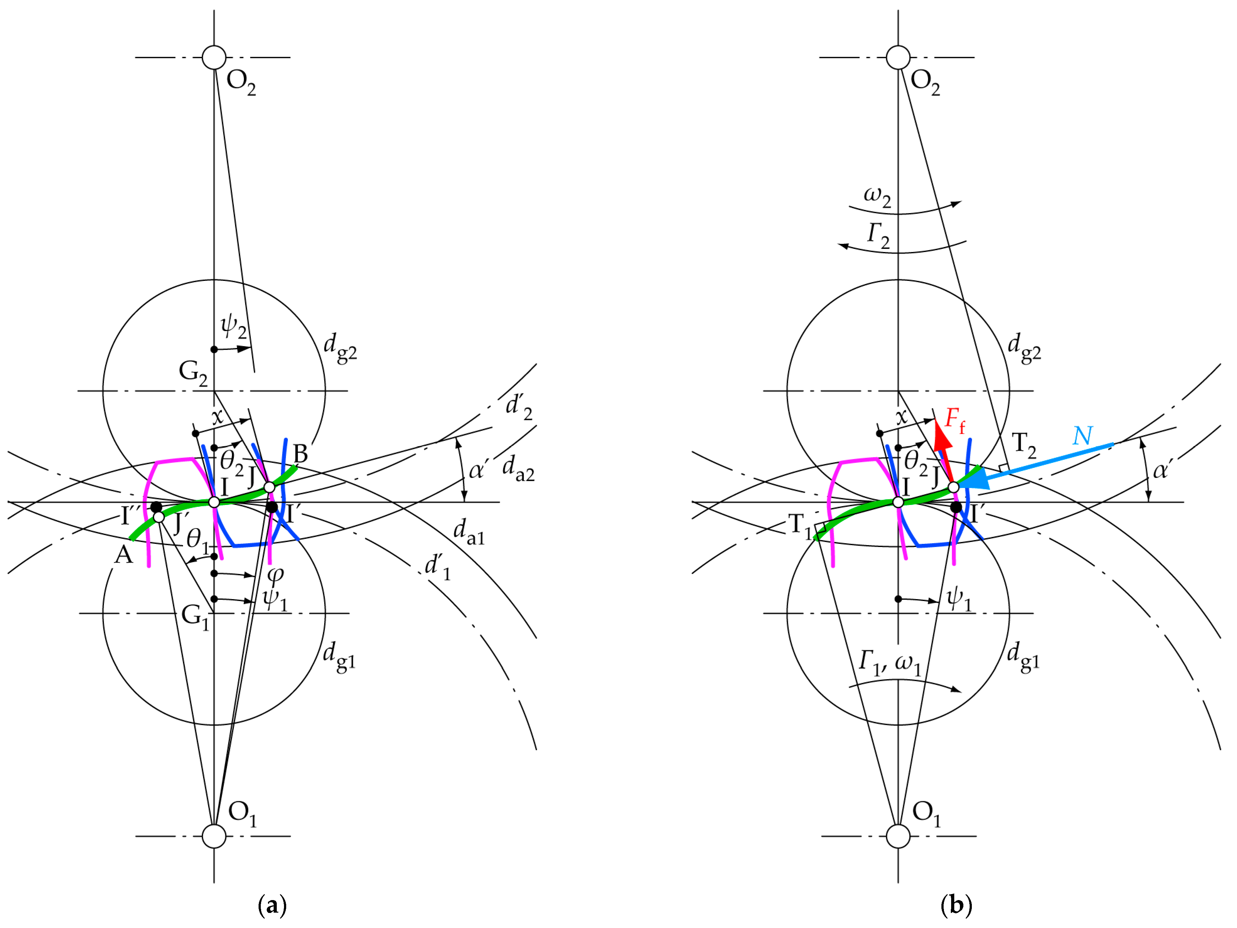
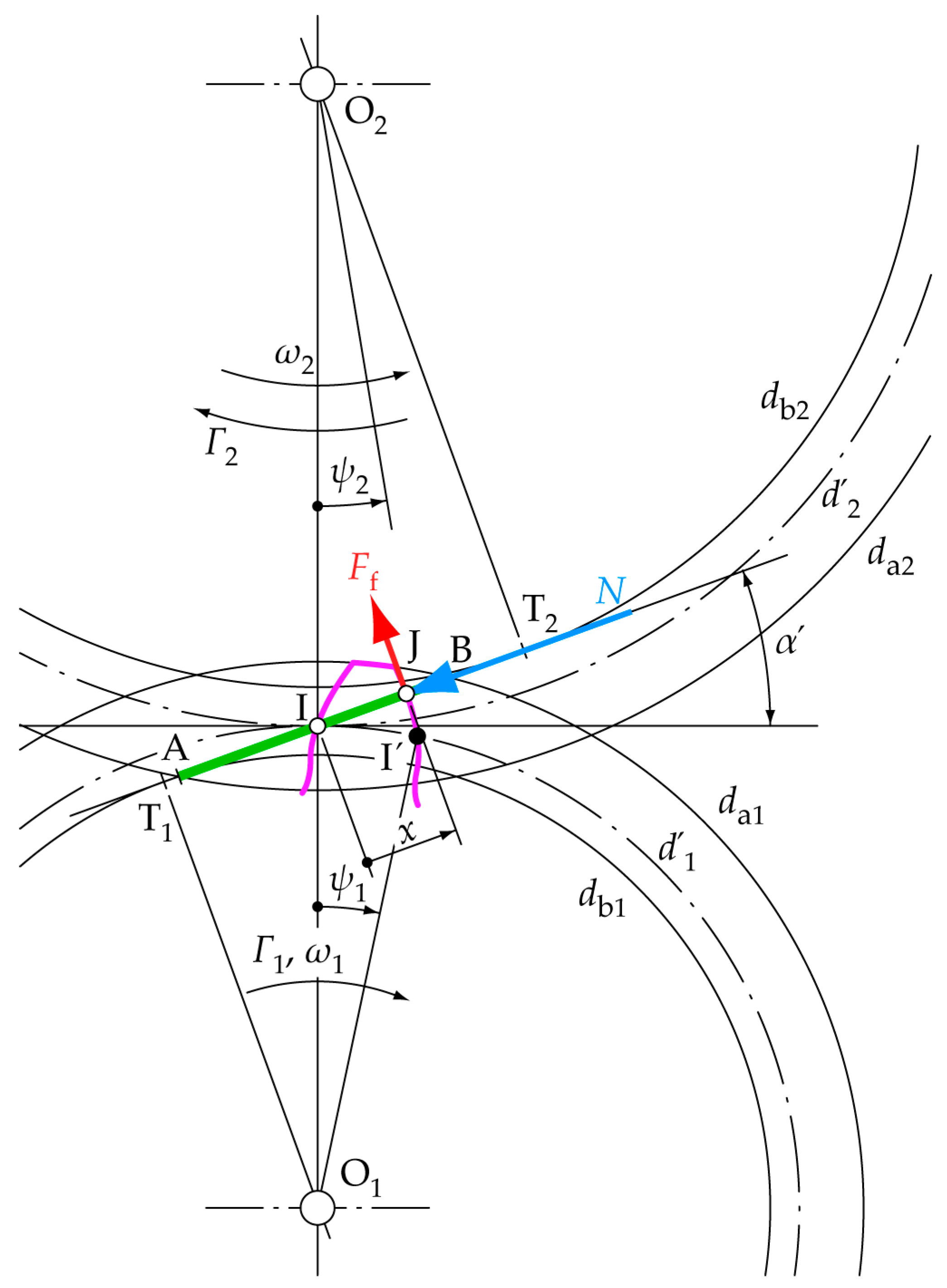
2.2. Cycloidal Output/Input Torque Ratio

The dynamics of the pinion, as observed from an inertial frame fixed to the bench, are analyzed to determine the relationship between output torque Γ2 and input torque Γ1 for the cycloidal profile.
Figure 2a illustrates the path of contact of the cycloidal profile (line AIB) formed by the epicycloid and the hypocycloid. These profiles are generated by rolling (without sliding) the disk with diameter dg1 and center G1 and the disk with diameter dg2 and center G2 along the perimeter of the pinion, centered at O1 with a pitch diameter of d1, and the wheel, centered at O2 with a pitch diameter of d2. Additionally, in this Figure, da1,2 represent the head diameters; α′ is the pressure angle; ψ1,2 are the rotated angles; and A, B, I, and J are the approach start contact point, recess end contact point, pitch point, and an arbitrary contact point, respectively.
Figure 2b illustrates a pinion’s tooth in a generic configuration of the gear sequence along with the forces acting on the contact point with the corresponding wheel’s tooth and the input torque to the shaft. In this Figure, Γ1,2, ω1,2, N, and Ff represent the torques, angular velocities, normal force, and frictional force, respectively.
A unitary contact ratio, εα, is adopted (i.e., there is no overlap between contacting tooth pairs) to compare the profiles while keeping the results as instructive as possible.
When the pinion rotates with an angular velocity ω1, and if there is a relative speed at the tooth contact point, the frictional force F f can be defined by the Coulomb dry friction model, as proposed by Jiang [45].
F f = μ   N   sign ψ 1
where the function’s sign represents the change in the frictional force vector’s sign when the contact point trespasses the pitch point (I).
In order to simplify the notation, the parameters ch and ce are introduced as follows:
c h = d g 1 d 1
c e = d g 2 d 1
Figure 2b depicts the forces applied to an arbitrary contact point J between the two teeth. By applying the AMT, first at the center of the pinion (Equation (24)) and then at the center of the wheel (Equation (35)), Equations (41) and (42) are obtained; the first is valid during the approach action (ψ1 < 0) and the second is applicable during the recess action of the gear (ψ1 ≥ 0).

2.2.1. Pinion

Γ 1 N d 1 2 cos α F f T 1 J ¯ = 0
If ψ1 < 0
x = d g 1 sin θ 1 2
F f T 1 J ¯ = μ N T 1 I ¯ + x = μ N d 1 2 sin α d g 1 sin θ 1 2
α = θ 1 2
The arc IJ′ has the same length as II″:
d g 1 2 θ 1 = d 1 2 ψ 1 ;   θ 1 2 = d 1 2 d g 1 ψ 1 = ψ 1 2 c h
Equation (24) yields
Γ 1 = N d 1 2 cos ψ 1 2 c h μ 1 2 c h sin ψ 1 2 c h
If ψ1 ≥ 0
x = d g 2 sin θ 2 2
F f T 1 J ¯ = μ N T 1 I ¯ + x = μ N d 1 2 sin α + d g 2 sin θ 2 2
α = θ 2 2
The arc IJ has the same length as II′:
d g 2 2 θ 2 = d 1 2 ψ 1 ;   θ 2 2 = d 1 2 d g 2 ψ 1 = ψ 1 2 c e
Equation (24), in this case, yields
Γ 1 = N d 1 2 cos ψ 1 2 c e + μ 1 + 2 c e sin ψ 1 2 c e

2.2.2. Wheel

Γ 2 + N d 2 2 cos α + F f T 2 J ¯ = 0
If ψ1 < 0
F f T 2 J ¯ = μ N T 2 I ¯ x = μ N d 2 2 sin α + d g 1 sin θ 1 2
Analogous to the previous development, Equation (35) yields to Equation (37), where the gear ratio i is defined by Equation (38).
Γ 2 = N d 1 2 i cos ψ 1 2 c h μ i + 2 c h sin ψ 1 2 c h
i = ω 1 ω 2
If ψ1 ≥ 0
F f T 2 J ¯ = μ N T 2 I ¯ x = μ N d 2 2 sin α d g 2 sin θ 2 2
In this case, Equation (35) yields
Γ 2 = N d 1 2 i cos ψ 1 2 c e + μ i 2 c e sin ψ 1 2 c e
Output torque/input torque ratio:
If ψ1 < 0
Γ 2 Γ 1 = i cos ψ 1 2 c h μ i + 2 c h sin ψ 1 2 c h cos ψ 1 2 c h μ 1 2 c h sin ψ 1 2 c h
If ψ1 ≥ 0
Γ 2 Γ 1 = i cos ψ 1 2 c e + μ i 2 c e sin ψ 1 2 c e cos ψ 1 2 c e + μ 1 + 2 c e sin ψ 1 2 c e
In order to calculate the coefficient of friction with the EHL methods described in Section 2.1, the rolling velocities, u1 and u2, at the contact point are determined as follows:
If ψ1 < 0
u 1 = O 1 J ¯   ω 1 sin ψ 1 2 c h + φ
u 2 = O 1 J ¯   ω 1 sin ψ 1 2 c h + φ d g 1 sin ψ 1 2 c h ω 1 1 + 1 i
with
O 1 J ¯ = d g 1 2 sin ψ 1 c h sin φ
φ = arctan d g 1 sin ψ 1 c h d 1 d g 1 1 cos ψ 1 c h
If ψ1 ≥ 0
u 1 = O 1 J ¯   ω 1 sin ψ 1 2 c e + φ
u 2 = O 1 J ¯   ω 1 sin ψ 1 2 c e + φ + d g 2 sin ψ 1 2 c e ω 1 1 + 1 i
with
O 1 J ¯ = d g 2 2 sin ψ 1 c e sin φ
φ = arctan d g 2 sin ψ 1 c e d 1 + d g 2 1 cos ψ 1 c e

2.3. Involute Profile Output/Input Torque Ratio

Figure 3 illustrates a pinion gear tooth in a generic configuration of the gear sequence, along with the forces acting at the contact point with the corresponding wheel gear tooth and the input torque to the shaft. The nomenclature used is analogous to that in the cycloidal case. Additionally, in this Figure, db1,2 represent the base diameters and T1,2 indicate the tangential points between the line of action and the base circles.
As in the previous case, a unitary contact ratio, εα, is adopted to compare the profiles while keeping the results as instructive as possible. The curvature radii of the involute profile for the pinion and the wheel at an arbitrary contact point, J, are, respectively,
R 1 = T 1 J ¯ = T 1 I ¯ + x = d 1 2 sin α + ψ 1 d b 1 2
R 2 = T 2 J ¯ = T 2 I ¯ x = d 2 2 sin α ψ 1 d b 1 2
Applying the AMT while assuming constant angular velocity—first at the center of the pinion (positive clockwise) and then at the center of the wheel (positive counterclockwise)—results in the following expressions:

2.3.1. Pinion

Γ 1 N d b 1 2 F f R 1 = 0
where F f follows Equation (21).

2.3.2. Wheel

Γ 2 + N d b 2 2 + F f R 2 = 0
where Ff follows Equation (21) as well.
Therefore, the output torque/input torque ratio is:
Γ 2 Γ 1 = d b 2 2 + sign ψ 1 μ d b 2 2 tan α ψ 1 d b 1 2 d b 1 2 + sign ψ 1 μ d b 1 2 tan α + ψ 1 d b 1 2
Equation (55) can be rearranged as the following:
Γ 2 Γ 1 = i + sign ψ 1 μ i tan α ψ 1 1 + sign ψ 1 μ tan α + ψ 1
Equation (56) represents the evolution of the input torque to output torque ratio as a function of the coefficient of friction, the pressure angle, the gear ratio, and the angle rotated by the pinion. In this case, the rolling velocities u1 and u2 at the contact point are given by
u 1 = ω 1 R 1
u 2 = ω 2 R 2

2.4. Energy Efficiency

In this context, the energy efficiency of a gear contact can be formulated as the ratio between the output energy and the input energy over one complete pairing teeth contact cycle, assuming constant angular velocities. Expressed in terms of the input power P1, the output power P2 and the duration time te, of an approach–pitch–recess action, the following can be written:
η = 0 t e P 2 d t 0 t e P 1 d t = 0 t e Γ 2 ω 2 d t 0 t e Γ 1 ω 1 d t = 1 i ψ 1 min ψ 1 max Γ 1 Γ 2 Γ 1 ψ 1 d ψ 1 ψ 1 min ψ 1 max Γ 1 d ψ 1
where ψ1min and ψ1max are the start and the end of the pinion angular coordinate during the approach–pitch–recess action and Γ2/Γ1 follows the Equations (41), (42) (cycloidal) and (56) (involute). If we assume a constant input torque, Equation (59) yields
η = 1 i ψ 1 min ψ 1 max Γ 2 Γ 1 ψ 1 d ψ 1 ψ 1 max ψ 1 min

3. Results

In this section, the iterative process used to obtain the coefficient of friction required to simulate the torque ratio values is detailed. Additionally, the cycloidal profile is simulated in terms of energy efficiency concerning the generation diameters dg1,2, expressed as dimensionless with respect to the pinion’s pitch diameter, along with a discussion of their limitations. Based on these results, some optimal auxiliary centrode diameters are selected. Finally, simulations comparing the energy efficiency of the involute profile with that of the cycloidal profile are conducted with varying gear dimensions (pinion pitch diameter) and the gear ratio i.

3.1. Iterative Process to Determine the Coefficient of Friction and the Torque Ratio

To determine the torque ratio, an iterative calculation process (Figure 4) which involves coupling the coefficient of friction with the LMT and AMT is necessary.
Given an arbitrary contact point along the path of contact, the steps are as follows:
  • Step 1: Calculate the geometric and the kinematic parameters Ve, Vs, SRR, and R.
  • Step 2: Determine the torque ratio Γ2/Γ1 and the normal force N by applying the LMT and AMT; an initial value for μ and a maximum target error εmax are required.
  • Step 3: Calculate the maximum Hertzian pressure pH, the average pressure p, as well as the normal load per unit width W′.
  • Step 4: Recalculate the coefficient of friction using the formulation of the selected friction model.
The process is repeated until the error ε is under the pre-established threshold value, which is set to εmax = 0.0001 for this study. The iteration process is implemented using Matlab R2024a software.

3.2. Cycloidal Profile: Efficiency with Respect to the Auxiliary Centrode Diameters and Their Limits

The efficiency of the cycloidal profile in relation to the auxiliary centrode diameters is shown in Figure 5 and Figure 6 for the EHL and MEHL analytical models, respectively.
The parameters used for these simulations are presented in Table 3. These parameters are fixed according to Xu [39] and Xu et al. [40] and complement with the required parameters for the case of MEHL model according to Masjedi and Khonsari [41].
Since the auxiliary centrode diameters, dg1 and dg2, are not defined for the involute tooth profile, efficiency with respect to these parameters remains constant; therefore, the graphical representation in Figure 5 and Figure 6 would appear, if drawn, as a horizontal plane. The red curve depicted represents the intersection between this plane and the surface that describes the efficiency of the cycloidal profile. Thus, this red curve indicates equal efficiency for both profiles. Assuming, for example, dg1 = dg2, the efficiency of the involute profile is equal to that of the cycloidal profile at dg1,2 ≈ 0.22·d1 in the EHL model and at dg1,2 ≈ 0.17·d1 in the MEHL model, with no significant differences concerning the gear ratio or the module.
In all cases, it is observed that efficiency improves as the auxiliary centrode diameters dg1,2 are reduced and as both the gear ratio and the gear size (module) are increased. By decreasing the auxiliary centrode diameters from 0.4·d1 to 0.1·d1, the efficiency increases from 0.11% to 0.19% in EHL and 0.39% to 0.57% in MEHL. Similarly, by changing the gear ratio from 1 to 3, the efficiency increases from 0.07% to 0.12% in EHL and 0.12% to 0.30% in MEHL. Finally, by increasing the gear module from 2 mm to 6 mm, the efficiency improvement results in an increase of between 0.03% and 0.11% in the EHL model and 0.11% and 0.15% in the MEHL model.
Nevertheless, the trend observed when reducing the auxiliary centrode diameters has some limitations (Figure 7):
  • The pressure angle α′ increases at both ends of the path of contact as dg1,2 decrease. Consequently, the normal force N at the contact point becomes larger for a given input torque, leading to increased fatigue damage on gear tooth surfaces and higher loads on the shafts. Additionally, with a higher pressure angle, the center distance tolerance between the pinon and the wheel has a greater influence on the dimensional errors of the ideal contact point between the meshing teeth.
  • The tooth height increases as dg1,2 diminishes to maintain a constant contact ratio, resulting in a larger tooth bending moment.
The aforementioned variations are illustrated in Figure 8. In the previous example, the involute profile has a tooth height of 2.01 mm and a pressure angle of 20°. According to the figure, the auxiliary centrode diameters that yield similar values in the cycloidal gear are dg1,2 = 0.17·d1, resulting in a maximum pressure angle of α′ = 19.6° and a pinion tooth height (contact height) of 2.06 mm. Moreover, these results remain consistent regardless of other gear sizes and gear ratios. The pressure angle shows no significant differences with respect to variations in the module or gear ratio, nor does the gear ratio significantly influence tooth height. The module affects the tooth height in a proportional manner, and, therefore, the relative auxiliary centrode diameters dg1,2/d1 are also invariant.

3.3. Contact Conditions, Torque Ratio, and Efficiency Comparison Between Involute and Cycloidal Profiles

Using the same parameters mentioned in the previous set of simulations, and with the auxiliary centrode diameters fixed at dg1,2 = 0.17·d1, Equations (41), (42), and (56), which describe the output/input torque ratio, have been calculated to establish a comparison framework between the two profiles during the gearing cycle (approach—pitch—recess). A sample plot is shown in Figure 9d with i = 1 and m0 = 2 mm. Other gear ratios and modules are not shown because their performances follow the same trend.
In order to facilitate the comparison, Figure 9 also shows the relative surface sliding velocities, Vs, the sum of the rolling velocities, Vr, the combined radius of curvature, R, and, for both lubrication models, the normal load, N, and the coefficient of friction, µ. In Figure 9a, both profiles show similar Vs with a null value at the pitch point, which is the expected behavior. In the involute profile, Vr is constant because the sum of curvature radius of the paring teeth at any arbitrary contact point is constant. In the cycloidal profile instead, Vr has a null value at the pitch point because the tangent direction to the contact surfaces follows, at this point, the gear center-to-center direction and, hence, there are neither rolling nor sliding velocities in this configuration.
In both lubrication analytical models, the normal load of the cycloidal profile remains lower than the involute one along almost all of the path of contact (Figure 9b), caused by a lower average pressure angle (not depicted). Moreover, the combined radius of curvature, R, is bigger at both ends of the path of contact in the cycloidal profile as a consequence of the pairing concave–convex surfaces, while it is null at the pitch point (transition point between the hypocicloid and the epycicloid). Although the cycloidal case has a lower normal force, the null R at the pitch point leads an indetermination in the calculation, creating a numerical asymptotic infinite Hertzian pressure and an increment of the coefficient of friction at this point (Figure 9c). On the contrary, the coefficient of friction in the involute profile decreases at this point because the sliding velocity is null and the Hertzian pressure is finite. In terms of efficiency, the differences in the coefficient of friction explains mainly the differences observed in the torque ratio (Figure 9d). For both lubrication analytical models, the cycloidal profile is more efficient at the start and the end of the path of contact, while the involute is superior around the pitch point.
Figure 10 presents a sensitivity analysis of the efficiency of both profiles concerning the module m0 and the gear ratio i. Within the evaluated ranges, and for both lubrication analytical models, there is no noticeable difference between the efficiencies of the cycloidal and the involute profiles. The largest difference is as small as approximately 0.01% (MEHL). In all cases, increasing the module and the gear ratio improves efficiency, tending to converge to a constant value.

4. Conclusions

In machinery design, evaluating energy issues when selecting among viable solutions is becoming an increasingly relevant topic. Transmissions using spur gears are widely implemented in industrial applications. In this study, the authors present a comparative analysis of the energy efficiency of a spur gear transmission generated using an involute profile versus one with a cycloidal profile. To isolate the effect of the profile used, the following assumptions have been made:
  • A unitary contact ratio.
  • No bending deformation.
  • Nominal profile dimensions without tolerances.
The analysis is conducted by applying the Linear Momentum and the Angular Momentum Theorems to the solid pinion and the solid wheel. The frictional force is modeled by two widely accepted models based on EHL and MEHL.
While some studies address the efficiency of the involute profile in relation to geometric parameters, none focus on the cycloidal one. Therefore, a key contribution of this study is to determine the sensitivity of the cycloidal profile regarding its energy efficiency while considering variations in the two auxiliary centrode diameters dg1,2. This analysis is essential for conducting a comparative evaluation between both profiles. For the cycloidal profile, the results indicate that smaller auxiliary centrode diameters lead to higher transmission efficiency for both lubrication analytical models. However, this trend has limitations dictated by the resulting geometry. Specifically, as the diameters decrease, the pressure angle α′ at both ends of the path of contact increases. Consequently, to transmit the same torque, the normal load N on the tooth surface becomes greater, which results in increased fatigue damage to the gear teeth surfaces and higher loads on the shafts. Additionally, smaller auxiliary centrode diameters require a greater tooth height to ensure the contact ratio, which in turn increases the bending moment on the tooth. In the cases studied, auxiliary centrode diameters of 0.17 times the pitch diameter of the pinion, d1, provide an approximate equivalence between the involute and cycloidal profiles regarding these limitations.
A second contribution of this study is the analytical comparison of the energy efficiency of the two aforementioned profiles and their sensitivity to gear size (module m0) and gear ratio i. The conclusions drawn are as follows:
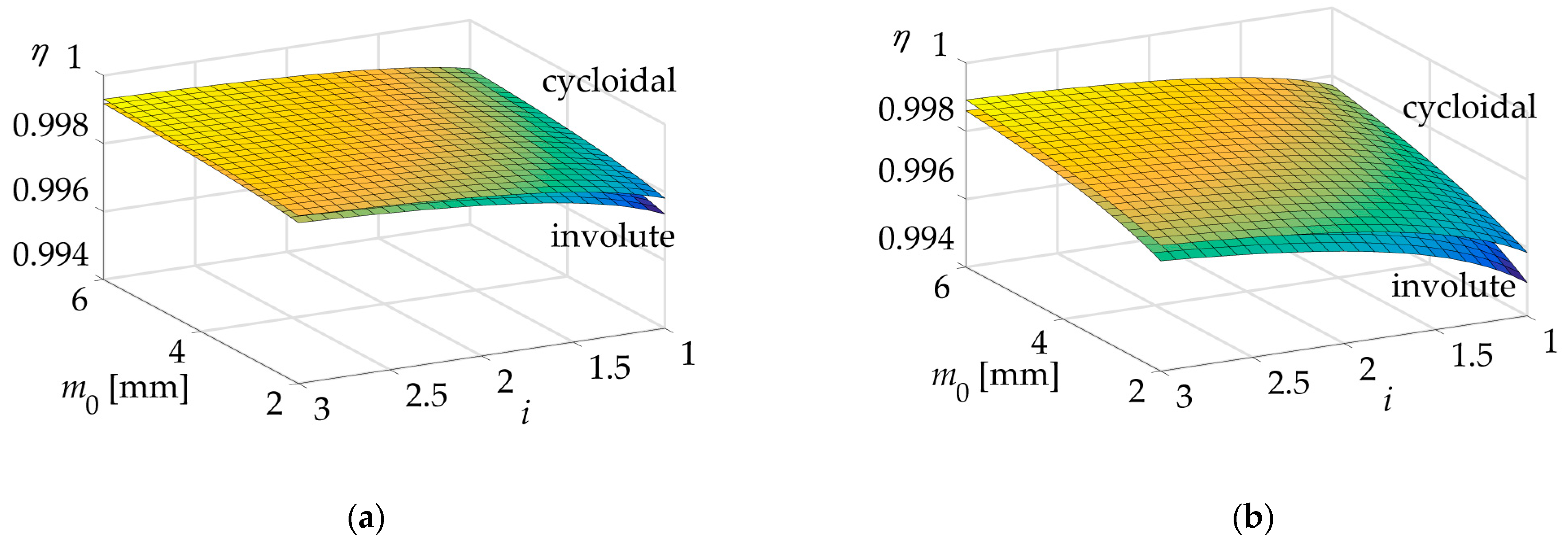
  • The cycloidal profile exhibits a performance nearly identical to that of the involute profile for both lubrication models, with observed differences being less than 0.01%.
  • The efficiency of both profiles increases with larger sizes and/or higher gear ratios for both models.
  • The efficiency of both profiles tends to converge to a constant value as the size and gear ratios increase in all cases.
Although the results for energy efficiency are very similar between the two profiles, a noticeable difference is observed regarding the lengths at which friction becomes significant. In both lubrication models, the cycloidal profile is more efficient at the start and end of the path of contact, while the involute profile performs better around the pitch point. This suggests a future research opportunity to design a hybrid profile which combines both profiles to maximize efficiency in spur gear transmissions.

Author Contributions

Conceptualization, J.M.V. and P.S.; data curation, P.S. and P.C.; formal analysis, J.M.V., P.S., P.C. and L.J.; funding acquisition, L.J.; investigation, J.M.V., P.S. and P.C.; methodology, J.M.V., P.S., P.C. and L.J.; resources, L.J.; software, J.M.V.; supervision, J.M.V. and P.C.; validation, J.M.V. and P.C.; visualization, J.M.V. and P.C.; writing—original draft, J.M.V., P.S., P.C. and L.J.; writing—review and editing, J.M.V., P.S., P.C. and L.J. All authors have read and agreed to the published version of the manuscript.

Funding

This research was funded by AGRUPS-2023 by the Universitat Politècnica de Catalunya.

Data Availability Statement

Data available on request. The data presented in this study are available on request from the corresponding authors.

Conflicts of Interest

The authors declare no conflicts of interest.

Appendix A. Curvature Radii at the Contact Point of a Cycloidal Profile

The calculation of the curvature radii of the conjugate profiles for cycloidal teeth at the contact point follows the procedure developed by Litvin and Fuentes [46]. The sequence of the path of contact has been divided into an approach action (contact between the pinion hypocycloid and the wheel epicycloid) and a recess action (contact between the pinion epicycloid and the wheel hypocycloid).

Appendix A.1. Approach Action (ψ1 < 0)

Figure A1 illustrates the geometry involved in determining the curvature radius at an arbitrary contact point J′ during the approach action. In this case, Sh is the center of curvature of the hypocycloid profile (pinion), and Se is the center of curvature of the epicycloid profile (wheel). Therefore, the curvature radii are the distances ShJ′ and SeJ′, respectively. By applying the law of sines and the law of cosines to triangle O2KI, we obtain
O 2 K ¯ 2   = d 2 2 2   + d g 1 cos θ 1 2 2   d 2   d g 1   cos θ 1 2 cos π α
O 2 K ¯ sin π α = d 2 / 2 sin γ 3 = d g 1 cos θ 1 2 sin γ 2
Therefore, the angles γ2 and γ3 can be obtained from Equations (28), (A1) and (A2) as follows:
γ 2 = arcsin n u m 1 d e n
γ 3 = arcsin n u m 2 d e n
n u m 1 = d g 1 cos ψ 1 2 c h sin π + ψ 1 2 c h
n u m 2 = d 2 2 sin π + ψ 1 2 c h
d e n = d 2 2 4 + d g   1 2   cos 2   ψ 1 2 c h d 2 d g 1   cos ψ 1 2   c h cos π   +   ψ 1 2   c h
The distances SeI and ShI are
S e I ¯ = d g 1 cos θ 1 2 tan γ 3 = d g 1 cos ψ 1 2 c h tan γ 3
S h I ¯ = d g 1 cos θ 1 2 tan γ 1 + α = d g 1 cos ψ 1 2 c h tan γ 1 ψ 1 2 c h
By subtracting coordinate x (shown in Figure A2) from SeI and ShI, we obtain the above-mentioned curvature radii
S e J ¯ = S e I ¯ x = d g 1 cos ψ 1 2 c h tan γ 3 + sin ψ 1 2 c h
S h J ¯ = S h I ¯ x = d g 1 cos ψ 1 2 c h tan γ 2 ψ 1 2 c h + sin ψ 1 2 c h
Figure A1. Curvature radius at contact point J′ of a cycloidal profile during approach action.
Machines 12 00943 g0a1

Appendix A.2. Recess Action (ψ1 ≥ 0)

Similarly to the previous case, Figure A2 illustrates the geometry involved in determining the curvature radius at an arbitrary contact point J during recess action. In this case, Sh is the center of curvature of the hypocycloid profile (wheel) and Se is the center of curvature of the epicycloid profile (pinion). The curvature radii are the distances ShJ and SeJ, respectively.
Equations (A12) and (A13) are the resulting expressions derived using a similar development as for the approach action.
S e J ¯ = d g 2 cos ψ 1 2 c e tan γ 3 + sin ψ 1 2 c e
S h J ¯ = d g 2 cos ψ 1 2 c e tan γ 2 + ψ 1 2 c e + sin ψ 1 2 c e
Figure A2. Curvature radius at contact point J of a cycloidal profile during recess action.
Machines 12 00943 g0a2

References

  1. Anderson, N.E.; Loewenthal, S.H. Effect of geometry and operating conditions on spur gear system power loss. J. Mech. Des. 1981, 103, 151–159. [Google Scholar] [CrossRef]
  2. Anderson, N.E.; Loewenthal, S.H. Design of spur gears for improved efficiency. J. Mech. Des. 1982, 104, 767–774. [Google Scholar] [CrossRef]
  3. Gupta, K.; Laubscher, R.F.; Davim, J.P.; Jain, N.K. Recent developments in sustainable manufacturing of gears: A review. J. Clean. Prod. 2016, 112, 3320–3330. [Google Scholar] [CrossRef]
  4. Pabiszczak, S.; Kowal, M. Efficiency of the eccentric rolling transmission. Mech. Mach. Theory 2022, 169, 104655. [Google Scholar] [CrossRef]
  5. Zhang, Y.; Hou, X.; Zhang, H.; Zhao, J. Numerical simulation on windage power loss of high-speed spur gear with baffles. Machines 2022, 10, 416. [Google Scholar] [CrossRef]
  6. Townsend, D.P. Lubrication and cooling for high speed gears. In Proceedings of the Original Equipment Manufacturing Design Conference, Philadelphia, PA, USA, 9–11 September 1985. [Google Scholar]
  7. Heingartner, P.; Mba, D. Determining power losses in helical gear mesh: Case study. In Proceedings of the ASME International Design Engineering Technical Conferences and Computers and Information in Engineering, Chicago, IL, USA, 2–6 September 2003. [Google Scholar]
  8. Anderson, N.E.; Loewenthal, S.H. Spur-Gear-System Efficiency at Part and Full Load; NASA Technical Paper: 1622; NASA Lewis Research Center: Cleveland, OH, USA, 1980; Volume 79, pp. 1–40.
  9. Britton, R.D.; Elcoate, C.D.; Alanou, M.P.; Evans, H.P.; Snidle, R.W. Effect of surface finish on gear tooth friction. J. Tribol. 2000, 122, 354–360. [Google Scholar] [CrossRef]
  10. Diab, Y.; Ville, F.; Velex, P. Prediction of power losses due to tooth friction in gears. Tribol. Trans. 2006, 49, 260–270. [Google Scholar] [CrossRef]
  11. Kalay, O.C.; Doğan, O.; Yılmaz, T.G.; Yüce, C.; Karpat, F. A comparative experimental study on the impact strength of standard and asymmetric involute spur gears. Measurement 2021, 172, 108950. [Google Scholar] [CrossRef]
  12. Jia, C.; He, Q.; Xiao, J.; Dong, H. Design and Analysis of Novel Non-Involute Cylindrical Gears with a Curved Path of Contact. Mathematics 2022, 10, 4290. [Google Scholar] [CrossRef]
  13. Liu, L.; Meng, F.; Ni, J. A novel non-involute gear designed based on control of relative curvature. Mech. Mach. Theory 2019, 140, 144–158. [Google Scholar] [CrossRef]
  14. Liu, L.; Ni, J. An efficient dynamics model of spur gear drive with curved path of contact in mixed elastohydrodynamic lubrication. Mech. Ind. 2022, 23, 1–12. [Google Scholar] [CrossRef]
  15. Ikejo, K.; Nagamura, K.; Tutulan, F.G. Friction loss of non-involute tooth profile gears. In Proceedings of the ASME International Design Engineering Technical Conferences and Computers and Information in Engineering, Long Beach, CA, USA, 24–28 September 2005. [Google Scholar]
  16. Peng, Y.; Song, A.; Shen, Y.; Lin, X. A novel arc-tooth-trace cycloid cylindrical gear. Mech. Mach. Theory 2017, 118, 180–193. [Google Scholar] [CrossRef]
  17. Novikov, M.L. USSR Patent No. 109750. 1956. [Google Scholar]
  18. Marques, P.M.T.; Martins, R.C.; Seabra, J.H.O. Power loss and load distribution models including frictional effects for spur and helical gears. Mech. Mach. Theory 2016, 96, 1–25. [Google Scholar] [CrossRef]
  19. Diez-Ibarbia, A.; Fernandez-del-Rincon, A.; De-Juan, A.; Iglesias, M.; Garcia, P.; Viadero, F. Frictional power losses on spur gears with tip reliefs. The friction coefficient role. Mech. Mach. Theory 2018, 121, 15–27. [Google Scholar] [CrossRef]
  20. Yue, K.; Kang, Z.; Zhang, M.; Wang, L.; Shao, Y.; Chen, Z. Study on gear meshing power loss calculation considering the coupling effect of friction and dynamic characteristics. Tribol. Int. 2023, 183, 108378. [Google Scholar] [CrossRef]
  21. Mughal, H.; Dolatabadi, N.; Rahmani, R. An integrated tribodynamic model for investigation of efficiency, durability and NVH attributes of gear mesh in electric vehicle powertrains. Tribol. Int. 2023, 189, 108977. [Google Scholar] [CrossRef]
  22. Liu, L.; Kong, R.; Chen, Z. Prediction of mechanical efficiency of spur gear pairs based on tribo-dynamics model of multi-tooth meshing. Proc. Inst. Mech. Eng. Part J J. Eng. Trib. 2024, 238, 880–893. [Google Scholar] [CrossRef]
  23. Fang, S.; Liu, Y.; Wang, H.; Taguchi, T.; Takeda, R. Research on the compensation method for the measurement error of cycloidal gear tooth flank. Int. J. Precis. Eng. Manuf. 2014, 15, 2065–2069. [Google Scholar] [CrossRef]
  24. Abdulkareem, A.A.; Abdullah, M.Q. Theoretical Formulation of Maximum Bending Stress Value and Location for Cycloid Teeth Spur Gear. J. Mech. Eng. Res. Dev. 2021, 44, 303–314. [Google Scholar]
  25. Hmoad, M.; Hamza, N.R.; Abdulkareem, T.M.; Abdullah, A.A. The Effect of Different Design Parameters on the Cycloid Teeth-Straight Bevel Gear Bending Stress. J. Mech. Eng. Res. Dev. 2020, 43, 109–118. [Google Scholar]
  26. Tariq, H.; Galym, Z.; Amrin, A.; Spitas, C. Assessment of contact forces and stresses, torque ripple and efficiency of a cycloidal gear drive and its involute kinematical equivalent. Mech. Based Des. Struct. Mach. 2022, 52, 1304–1323. [Google Scholar] [CrossRef]
  27. Antoniak, P.; Bednarczyk, S. Determination of mechanical power loss of the output mechanisms with serially arranged rollers in cycloidal gears while taking into account manufacturing tolerances. Machines 2024, 12, 345. [Google Scholar] [CrossRef]
  28. Wang, X.; Wang, H.; Li, L.; Hao, L. An improved transmission efficiency prediction method for nonlinear characteristics of the cycloid reducer. Proc. Inst. Mech. Eng. Part C J. Mech. Eng. Sci. 2024, 238, 10266–10284. [Google Scholar] [CrossRef]
  29. Zhao, Z.; Yang, Y.; Han, H.; Ma, H.; Wang, H.; Li, Z. Meshing characteristics of spur gears considering three-dimensional fractal rough surface under elastohydrodynamic lubrication. Machines 2022, 10, 705. [Google Scholar] [CrossRef]
  30. Rebbechi, B.; Oswald, F.B.; Townsend, D.P. Measurement of gear tooth dynamic friction. In Proceedings of the Seventh International Power Transmission and Gearing Conference Sponsored by the American Society of Mechanical Engineers, San Diego, CA, USA, 6–9 October 1996. [Google Scholar]
  31. Park, C.I.L. Tooth friction force and transmission error of spur gears due to sliding friction. J. Mech. Sci. Technol. 2019, 33, 1311–1319. [Google Scholar] [CrossRef]
  32. He, S.; Gunda, R.; Singh, R. Effect of sliding friction on the dynamics of spur gear pair with realistic time-varying stiffness. J. Sound Vib. 2007, 301, 927–949. [Google Scholar] [CrossRef]
  33. He, S.; Cho, S.; Singh, R. Prediction of dynamic friction forces in spur gears using alternate sliding friction formulations. J. Sound Vib. 2008, 309, 843–851. [Google Scholar] [CrossRef]
  34. Misharin, J.A. Influence of the Friction Conditions on the Magnitude of the Friction Coefficient in the Case of Rolling with Sliding. In Proceedings of the International Conference on Gearing, London, UK, 23–25 September 1958. [Google Scholar]
  35. ISO/TC 60/SC 2 Gear Capacity Calculation. Available online: https://www.iso.org/es/contents/data/committee/04/92/49242.html (accessed on 20 December 2024).
  36. Benedict, G.H.; Kelley, B.W. Instantaneous coefficients of gear tooth friction. ASLE Trans. 1961, 4, 59–70. [Google Scholar] [CrossRef]
  37. O’donoghue, J.P.; Cameron, A. Friction and temperature in rolling sliding contacts. ASLE Trans. 1966, 9, 186–194. [Google Scholar] [CrossRef]
  38. Drozdov, Y.N.; Gavrikov, Y.A. Friction and scoring under the conditions of simultaneous rolling and sliding of bodies. Wear 1968, 11, 291–302. [Google Scholar] [CrossRef]
  39. Xu, H. Development of a Generalized Mechanical Efficiency Prediction Methodology for Gear Pairs. Ph.D. Thesis, Ohio State University, Columbus, OH, USA, 2005. [Google Scholar]
  40. Xu, H.; Kahraman, A.; Anderson, N.E.; Maddock, D.G. Prediction of mechanical efficiency of parallel-axis gear pairs. J. Mech. Des. 2007, 129, 58–68. [Google Scholar] [CrossRef]
  41. Masjedi, M.; Khonsari, M.M. An engineering approach for rapid evaluation of traction coefficient and wear in mixed EHL. Tribol. Int. 2015, 92, 184–190. [Google Scholar] [CrossRef]
  42. Tian, X.; Kennedy Jr, F.E. Maximum and average flash temperatures in sliding contacts. J. Tribol. 1994, 116, 167–174. [Google Scholar] [CrossRef]
  43. Masjedi, M.; Khonsari, M.M. Film thickness and asperity load formulas for line-contact elastohydrodynamic lubrication with provision for surface roughness. J. Tribol. 2012, 134, 011503. [Google Scholar] [CrossRef]
  44. Roelands, C.J.A. Correlational Aspects of the Viscosity-Temperature-Pressure Relationship of Lubricating Oils. Ph.D. Thesis, Technical University of Delft, Delft, The Netherlands, 1966. [Google Scholar]
  45. Jiang, H.; Liu, F. Dynamic modeling and analysis of spur gears considering friction–vibration interactions. J. Braz. Soc. Mech. Sci. Eng. 2017, 39, 4911–4920. [Google Scholar] [CrossRef]
  46. Litvin, F.L.; Fuentes, A. Gear Geometry and Applied Theory, 2nd ed.; Cambridge University Press: Cambridge, UK, 2004. [Google Scholar]
Figure 1. Coefficient of friction versus SRR ratio for the indicated models.
Machines 12 00943 g001
Figure 2. Cycloidal profile: (a) geometry; (b) forces on the contact point between pairing teeth.
Machines 12 00943 g002
Figure 3. Involute profile: geometry and forces on the contact point J between pairing teeth.
Machines 12 00943 g003
Figure 4. Iterative process to determine the coefficient of friction μ.
Machines 12 00943 g004
Figure 5. Efficiency of the cycloidal profile vs. auxiliary centrode diameters dg1,2; EHL model: (a) Same module m0 = 2 mm, different gear ratio i; (b) same gear ratio i = 1, different module.
Machines 12 00943 g005
Figure 6. Efficiency of the cycloidal profile vs. auxiliary centrode diameters dg1,2; MEHL model: (a) Same module m0 = 2 mm, different gear ratio i; (b) Same gear ratio i = 1, different module.
Machines 12 00943 g006
Figure 7. Cycloidal profile: Effect of auxiliary centrode diameters dg1,2 on the maximum pressure angle and tooth height: (a) dg1,2 = 0.1·d1; (b) dg1,2 = 0.25·d1.
Machines 12 00943 g007
Figure 8. Cycloidal profile: Tooth height and pressure angle α′ vs. relative size of auxiliary centrode diameters dg1,2/d1.
Machines 12 00943 g008
Figure 9. Contact conditions along the path of contact function of ψ1, for the involute and cycloidal profiles: (a) rolling velocities, Vr, sliding velocities, Vs, and combined radius of curvature, R; for EHL and MEHL models the normal force N (b), the coefficient of friction µ (c) and the output/input torque ratio (d).
Machines 12 00943 g009aMachines 12 00943 g009b
Figure 10. Efficiency comparison of cycloidal and involute profiles: (a) EHL; (b) MEHL analytical models.
Machines 12 00943 g010
Table 1. Lubricant properties for gear oil 75W90 [39].
ParameterMeasured Temperature Value
Density100 °C0.78 kg/L
Kinematic viscosity40 °C97.5 cSt
100 °C14.31 cSt
Specific gravity15.6 °C0.86
Specific heat100 °C2.29 kJ/(kg·C)
Flash pointNot applicable207 °C
Table 2. Required parameters for obtaining the coefficient of friction in EHL and MEHL models.
ParameterValueParameterValue
R 15 mmcp 2434 J/(kgK)
Ve 15 m/sΛlim 40.06
pH 12.0 GPaz 40.58
fc 10.12ρ 4769.2 kg/m3
E2231 GPaKT 40.03 K−1
S 20.20 μmα 41.5 × 10⁻⁸ m2/N
σ 20.20 μmν0 410 cP
Hv  2,36.0 GPaνk 413 cSt
K1,2 260.5 W/(mK)
1 Gear contact; 2 gear material; 3 carburizing surface treatment; 4 lubricant.
Table 3. Parameters for evaluating the efficiency of the cycloidal profile used in EHL and MEHL models.
ParameterValueParameterValue
z1 127 teethσ 20.20 μm
i  1[1.0; 3.0]Hv  2,36.0 GPa
m0 1[2.0; 6.0]K1,2 260.5 W/(mK)
α120° (for involute profile)cp 2434 J/(kgK)
b/d1 10.8Λlim 40.06
εα 11.0z 40.58
vt 112.5 m/sρ 4769.2 kg/m3
pH 1668 N/mm2 (at pitch point of involute profile)KT 40.03 K−1
fc 10.12α 41.5 × 10⁻⁸ m2/N
E2231 GPaν0 410 cP
S 20.20 μmνk 413 cSt
1 Gear geometry; 2 gear material; 3 carburizing surface treatment; 4 lubricant.
Disclaimer/Publisher’s Note: The statements, opinions and data contained in all publications are solely those of the individual author(s) and contributor(s) and not of MDPI and/or the editor(s). MDPI and/or the editor(s) disclaim responsibility for any injury to people or property resulting from any ideas, methods, instructions or products referred to in the content.

