1. Introduction
All research in the mining industry is currently focused on the development of new technologies [
1,
2] and combating natural hazards [
3,
4]. The former is carried out mainly based on a three-stage research level [
5,
6]. It consists of model tests, bench tests and operational tests [
7,
8]. Each of these research stages is interconnected. The most valuable tests are those conducted under operational conditions [
9,
10]. Their results ultimately determine the suitability and readiness level of a given technology [
11,
12]. The latter research area, concerned with combating natural hazards, is no less difficult to implement. The hazards mainly include rock mass tremors, methane hazards and water hazards [
13,
14]. Obtaining research results from these threats is now essential for the implementation of a potential new technology for the exploitation of a given raw material [
15,
16]. Conducting research analysis in the field of natural hazards in mines is very important for the implementation of new technologies [
17,
18]. The proper interpretation of these results allows for an assessment as to whether a given technology will be successfully developed and useful in such difficult conditions [
19,
20].
The powered roof support (see
Figure 1) in a mining complex (see
Figure 2) plays the most important role alongside the mining longwall shearer and the longwall scraper conveyor, which constitutes an element of the output haulage [
21,
22]. The roof support performs two functions in the complex. The first is to protect the machines and equipment, as well as the working crew, from the negative effects of rock mass impact [
23,
24]. This impact is characterised by shocks (underground earthquakes) that are mainly caused by exploitation [
25]. The powered roof support is adapted to take over such load from the rock mass [
26,
27]. This protection is provided by the safety valves of the hydraulic legs of the roof support in question [
28]. A powered roof support is a series of sections positioned side by side. Most often, it consists of about 150 pieces. They are connected by a sliding system to the longwall conveyor (scraper) on which the mining longwall shearer (header machine) moves. This combination forms a wall complex [
29,
30]. This complex can operate in an automatic mode if mining and geological conditions allow it. Most often, these types of complexes work based on manual control. In other words, they are operated by persons located in the longwall.
The powered roof support, in its construction, consists of floor bases (1) which form its foundation. It is also used to transfer the pressure of the rock mass to the floor. The floor base is connected to the canopy by hydraulic legs (2). The task of the canopy (3) is to support the ceiling. The load on the canopy is transferred directly to the hydraulic legs. Hydraulic legs are the main elements used to support the ceiling. They are built into the floor and canopy sockets. The shield support (4) is connected directly to the canopy. In its rear part, there are lemniscate tie rods (5) connected to the shield support and the floor base. The sliding system (6) is located in the centre part of the floor base. It is used to move the sections of the powered roof support and the longwall conveyor spacer. The roof support is also equipped with a system to control all phases of operation.
This paper aims to present the results of research and analysis for finding the optimal solution for the construction of a powered roof support. In this respect, damage was assumed to have occurred in the construction of the powered roof support bases. The measurements carried out under real conditions were compared to the pressure in the sub-piston space of the hydraulic leg. Based on these results, an analysis was carried out, in which it was determined that the resulting strains and stresses are formed in the floor base construction. The obtained pressure measurements from real conditions indicate the presence of too much pressure from the rock mass. Based on the Finite Element Method (FEM), a stress and strain simulation was performed for the floor base construction operating in the longwall [
31,
32]. This method is also being used successfully in other scientific disciplines [
33,
34]. Conclusions were drawn from the obtained results of the simulation (FEM), in which design changes were proposed for the floor base in question. The strain and stress simulations performed for the new design confirmed the correctness of the range of changes. Thus, a new solution for mining a longwall complex was introduced.
The presented publication presents research analysis concerning the stresses and strains caused by rock mass pressure on the powered roof support construction. As a result, the resulting stresses and strains that occurred in the powered roof support affected the formation of damage in the floor base construction. The floor base construction in the analysed case was two-fold (it consisted of two separate floor bases connected together by a sliding system). The results obtained from operational tests of pressure measurement in the space under the piston of the hydraulic leg revealed that the limit pressure value for which it is safe to work was exceeded. In this respect, the analysis carried out showed that such a high-pressure increase comes from the pressure of the rock layers on the powered roof support construction. The analysis of these results made it possible to formulate assumptions for carrying out a numerical analysis using the Finite Element Method (MES). In the first variant of this analysis, information was obtained about the susceptibility of the floor base construction to the resulting damage. The next step was to adopt an assumption for the development of an optimal solution for changes in the construction. Model studies were conducted based on the Finite Element Method (MES). The obtained results of the above modelling confirmed the correctness of assumed changes in the construction. The next variant was scientific bench tests, allowing the constructions to work in real conditions. This multi-variant approach allowed for the introduction of changes, as well as the launch of a new complex with this solution.
2. Materials and Methods
The determination of the procedure algorithm (see
Figure 3) to assess the damage of the powered roof support floor base construction is intended as a course of action to eliminate unnecessary errors. In the applied algorithm, a detailed analysis is carried out on the mining and geological conditions under which the construction in question operated. The operating conditions of the coal seam are among those that have a significant impact on the resulting nature of the damage to the floor base. The occurrence of too much overload in relation to the floor base construction manifests itself as cracks. In order to determine what force loads the floor base construction, as a result of the resulting pressure of the rock layers over the powered roof support causing the fatigue of its construction, pressure measurements were carried out in the sub-piston space of the hydraulic leg of the powered roof support. The described algorithm is shown in
Figure 3.
In this regard, a number of studies were conducted to obtain information about the pressure build-up in the sub-piston space of the hydraulic leg under the real conditions of the longwall. The results obtained from the measurement tests and their analysis allowed for an assessment stating that there is a high overload from the adjacent rock layers loading the powered roof support, which affects the overload of the floor base construction. As a result, some stress and strain were created. Based on the above, the author conducted a literature review [
35] on the stress and strain arising in the construction of the floor base. The literature review in this area is very large [
36]; the most important scientific works among the literature were selected [
37]. The method adopted, based on the literature, confirmed the resulting load cycles.
In order to find exposed points in the construction, model studies were carried out using ANSYS 2023 R2 software. The results obtained from the model analysis confirmed the area of the construction’s sensitivity to emerging cracks due to additional loading from the overlying rock mass. Based on the obtained analysis result, a change was proposed in the construction of the powered roof support bases. In the conducted model tests of the proposed design solution, the same loads were applied as in the original design. The obtained results confirmed the correctness of the adopted changes for the floor base construction. This, in turn, allowed for the introduction of the new construction to operate in the conditions of the longwall.
The powered roof support construction is a welded construction as a result of operating in real conditions in which the phenomenon of fatigue arises. The problem of fatigue is widely described in the literature [
38]. The operation of the powered roof support under conditions of variable loads over time, after exceeding a certain degree of intensity and a certain limit of the number of cycles, can lead to a complex combination of phenomena and changes defined by material fatigue in stress concentration zones. In terms of finding a solution to remove the effects created in the powered roof support floor base construction, the author of the publication developed an algorithm to quickly obtain the assumed effect.
3. Results
Based on the developed algorithm of procedure (see
Figure 3) and the adopted course of action, the paper’s author began to perform the research task described in Stage 1. This stage included carrying out tests under real conditions. They pertained to pressure increase measurements in the sub-piston space of the hydraulic leg. The implementation of mining and geological conditions were also taken into account in this stage, which could have an impact on the occurrence of damage to the floor base construction. An image of the floor base damage is presented in
Figure 4. The analysis of damage to the powered roof support construction in real conditions began with the installation of a measuring system in the sub-piston space of the hydraulic leg. The purpose of conducting these tests was to determine the increase in pressure in the sub-piston space in relation to the pressure of the rock layers located above the canopy support.
The geological construction of the rock layers on the exploited coal seam is of great importance for the operation of the entire longwall complex. Surrounding rocks can tend to shock the rock mass or to suddenly overload (direct pressure on the canopy with a specific force). In the analysed case, based on the obtained pressure measurement from the sub-piston leg space, the results of the analysis determined that the resulting pressure increase in the sub-piston space of the hydraulic leg causes a sudden pressure on the rock layers over the canopy of the powered roof support. The results of these measurements indicate that this type of pressure increase is due to rock layers that move at a certain speed; their deceleration takes place directly above the canopy section of the powered roof support (see
Figure 5). The induced pressure on the canopy has a direct effect on the cracking of the floor base construction. The hydraulic leg is directly connected to the floor base and it is this that mainly transfers the weight of the canopy to the floor base.
The obtained results of pressure tests from the sub-piston space indicate an excessive increase in the pressure that the hydraulic leg transfers to the floor base, and this affects the cracking of the floor base in the area where the sliding system of the section of the powered roof support operates, causing cracks. Cracks in the construction were revealed at the point where the floor base was joined with the sliding system. The direct cause that had an impact on the disclosure of structural defects of the floor base construction was the additional load from the rock layers lying above the canopy. This type of load is difficult to induce in scientific bench test (laboratory) conditions due to the weak power of the bench test. The impact of mining and geological conditions revealed a structural defect of the floor base that could not be predicted under bench testing conditions. In Stage 1 (procedure algorithm—see
Figure 3), the test results were obtained, which are presented in
Figure 6,
Figure 7 and
Figure 8. These results allowed for the determination of the nature of the rock mass operation. This was characterised by unfavourable loading, causing cracks in the rock layers. The analysis carried out from Stage 1 and the conclusions drawn allowed us to move to the second stage described in the algorithm of the procedure (see
Figure 3).
The above diagrams (see
Figure 6,
Figure 7 and
Figure 8) present the pressure measurements in the sub-piston space. The graphs from the tests obtained illustrate the persistently high pressure. The conclusion drawn from these tests is that the leg construction copes well with such a large increase in pressure. However, as a result of this, the floor base construction revealed damage. Observations were made of the pressure increase in the leg and the cracking of the floor base construction. This indicates a combination of events including the fact that the resulting additional load on the powered roof support was caused by the rock mass. This was manifested by an increase in pressure in the leg, which had a negative impact on the resulting damage to the construction. The analysis of the obtained test results indicates that the additional load from the rock mass can be determined based on measurements of the resulting pressure increase.
The liquid in the sub-piston space of the hydraulic leg has a certain amount of kinetic energy, which directly depends on the speed of the medium. With the increase in the flow velocity, the kinetic energy of the flowing medium also increases, as does the increase in the force vector in the direction of the flow. If this force encounters an object in a flow, and this object is a load from the rock mass, we refer to this pressure acting on its surface as dynamic pressure. In this case, the additional load from the rock mass on the leg causes an increase in pressure, which is defined as dynamic pressure generated in the sub-piston space of the hydraulic leg. The dependencies of the pressure increase in the sub-piston space caused by the load from the rock mass can be described by the following formula:
where
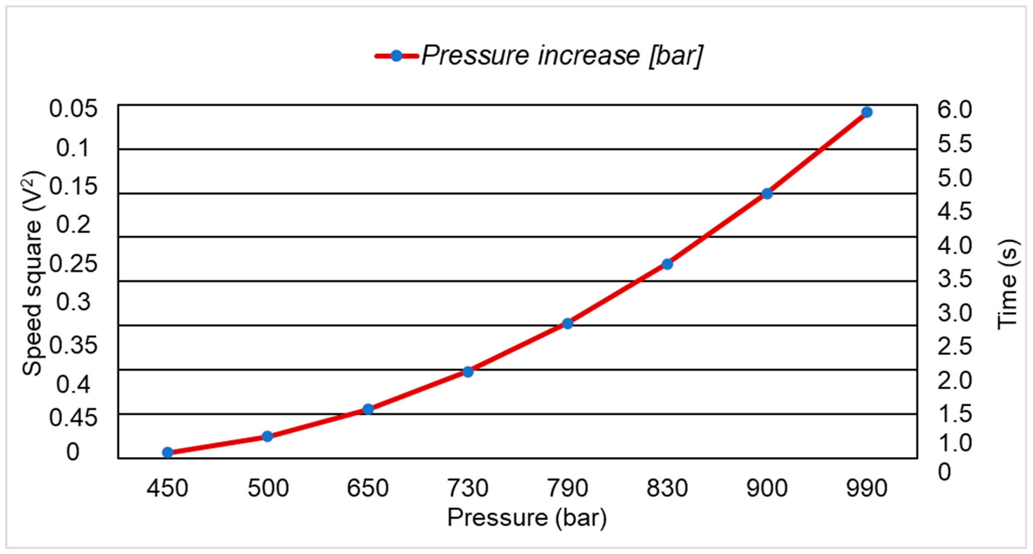
Table 1 presents the pressure increase depending on the square of the velocity. The velocity of the pressure of the rock layers on the powered roof support is taken from the literature [
39]. The velocity of the rock layers’ movement is determined to be between 0.2 and 0.4 m/s. The rock layers move as a result of the exploitation of the rock mass. Their stopping and slowing down moment is as a result of the powered roof support. The stopping of these rock masses results in the creation of an additional load on the powered roof support. This, in turn, affects the pressure increase in the sub-piston space of the hydraulic leg.
Table 1 presents the increase in pressure due to the additional load of the rock mass on the powered roof support. The density of the medium (997 kg/m
3) was assumed to be the same as that of water.
Figure 9 summarises the pressure increase based on theoretical calculations and based on measurements from actual conditions.
An analysis of the mining and geological conditions of the exploited longwall made it possible to theoretically determine the additional load of the rock mass on the powered roof support. The resulting damage to the floor base indicates an increase in pressure in the sub-piston space of the hydraulic leg. The assumptions adopted in Stage 1 of the developed algorithm (see
Figure 3) confirmed its usefulness and thus allowed for us to proceed to the second stage. The commencement of the second stage was made with a review of the literature [
40] related to the resulting strains and stresses. Based on the review of the literature [
41,
42,
43,
44], a method was chosen to determine the stresses and strains in theoretical terms, which allowed for an analysis of the resulting stresses and strains.
In Stage 2, it was assumed that a possible causative factor in the cracking of the floor base was the accumulation of partial fatigue effects in the material structure. In the construction of the floor base, the permissible stress values of the so-called excessive strain of the material were exceeded, where the final degradation of the material construction was the cracking of the floor base. The resulting level of the degradation of the floor base construction based on the selected literature can be assessed by adopting the linear hypothesis of damage accumulation, which is written with the following formula [
45]:
where
Ds—comulations of the floor base damage;
nt—number of cycles of destruction with constant amplitude of stresses;
Nt—number of cycles of accumulation of partial fatigue effects during the operation of the feller with the strength criterion exceeded.
The miner’s rule [
46], written in the above formula, is now the main standard in the fatigue design of metal structures. Due to its internal simplicity, which is based on the strength approach, it has been adopted in the leading standards for designing steel structures [
47,
48].
In the analysis of the damage that occurred, the source of the force was the rock mass pressure exceeding its limits on the powered roof support, causing the floor base to crack. The floor base construction was affected by dynamic and mass forces arising from the hydraulic leg pressed by the overlying rock masses. The source of this is forces and moments arising both inside and outside the hydraulic leg. However, the external load arises during the additional loading of the rock mass. In the present case, the resulting computational problem is the dynamic component of the force, which is influenced by the difficulty in obtaining precise measurements in real conditions. This also makes it difficult to describe the dynamic phenomenon occurring during the operation of the powered roof support.
The method used to determine stresses and strains based on a review of the literature allowed for us to carry out an analysis in order to obtain conclusions, allowing the transition to the third stage.
4. Discussion
The resistance of the material for the construction of the floor base to elastic strains can be determined using Young’s modulus [
49]. This dependency can be defined for any strain. The modulus of elasticity of the material from which the construction of the floor base is made for a given type of strain may be expressed by the slope of the stress and relative strain characteristics [
50,
51]. In accordance with current technical standards, Young’s modulus is determined via a static test of the material using a strength machine. In order to obtain the results of the analysis planned in the third stage of the adopted model, a research environment in the form of ANSYS software was used.
Numerical tests were carried out on the subject construction for which simulations were carried out based on Ansys software. The structure was damaged as a result of work in difficult mining and geological conditions. The purpose of this simulation test was to capture the focus of cracking, revealing defects. Then, according to the adopted algorithm of conduct (see
Figure 3), changes were made to achieve the intended effect in the form of a suitably durable construction. The change in the structure (as the original structure was damaged) was subjected to the same simulation tests. This was to demonstrate the difference and, in this respect, decide which construction will eventually be accepted for operation in mining conditions.
The powered roof support construction in the mining in the longwall must ensure the stability of the entire longwall complex. The built model was subjected to a strength analysis carried out using the Finite Element Method. Plastic strains were analysed, which were defined as the displacement of finite element nodes in relation to neighbouring ties. The plastic strain map for the X, Y and Z axes for the entire powered roof support construction is arranged in
Figure 10. The obtained analysis showed that the largest values of the resulting strain extend in the X-axis direction. Analysing the obtained results in the Y-axis direction, the strain is caused by the normal load impact of the structure. The obtained static analysis for the Z-axis for the assumed 5% overload of the structure indicates the absence of strain, which may affect the performance of the powered roof support. The results of the FEM study of static strain distribution occurring in the design of the powered roof support construction are presented in
Figure 10.
As a result of the performed simulations (
Figure 10), stress results were obtained for individual load tests of the powered roof support. These tests give information about the permissible load that can be applied to the powered roof support. The assumed stress state for the roof support construction may vary depending on the adopted support method of the so-called roof support load method. The results of the conducted tests revealed the places of stress concentration. The powered roof support is a construction consisting of three main elements (the canopy, the floor base and shield supports), the upper and lower parts of which are connected by hydraulic legs. The adopted load distribution in simulation studies may differ significantly from the actual loads obtained. The greatest strain value is located in the lower inner part of the floor base.
The results of the analysis showed the places with the greatest stress. These are located in the X-axis region, and are the structural connection points of the side walls separated by a wall connecting the two parts of the floor base to form its entirety. The resulting map of stresses in
Figure 11,
Figure 12,
Figure 13,
Figure 14 and
Figure 15 shows the number of cycles for the X-axis after which a crack may occur in this area.
The analysis carried out, which is depicted in
Figure 11,
Figure 12,
Figure 13,
Figure 14 and
Figure 15 above, identified the critical stress areas for the new construction of the floor base. The resulting load, based on model (simulation) tests for the construction of the floor base, was intended to determine what pressure the new structure will carry. These studies showed how the new floor base construction of the powered roof support floor base will carry loads or how the loads will be distributed as a result of additional loading from the rock mass. The purpose of the model tests, the results of which indicate that the proposed design change to the one that has been damaged (see
Figure 4), will allow for operation in a way that ensures optimal parameters. Thus, the methodology adopted for Stage 3 of the assumed process, as shown in
Figure 3, was confirmed. Based on the obtained test results, it can be concluded that permanent strain of the material should not occur in the operation of the structure in question, as their values can be very small.
5. Conclusions
The mining and geological conditions in this analysed case during the mining of the longwall had an adverse effect on the operation of the powered roof support. Such unfavourable operation was manifested by the failure of the sliding system located between the floor bases (see
Figure 4). In the area where the sliding system operates, the functionality of the floor base construction was lost due to damage. In this case, mining and geological conditions were the main influence on the loss of functionality of the roof support structure. It was manifested in an excessive load on the ceiling of the powered roof support construction. Thus, this overloaded the powered roof support to a range exceeding its yield strength. In the analysed case, the floor base operated on a substrate that was too soft, which also had an impact on its damage. The combination of these two conditions caused the phenomenon of fatigue in the powered roof support floor base.
The results obtained from measurements carried out in real conditions showed too large an increase, as well as the maintenance of high pressure exceeding the permissible limits. The author of the study concluded that the main reason for such a state is the additional load on the powered support from the rock mass. The adopted calculation model for the determination of stresses and strains confirms what cyclicity occurs in the floor base construction, which results in its cracking (see
Figure 4). Based on the model analysis, numerical tests were carried out to reveal sensitive points in the construction that are prone to cracking. The results obtained from the numerical analysis prompted the author to determine the assumptions that are aimed at introducing structural changes in the area of the powered roof support floor base.
Based on the assumptions, a new design for the floor base construction was prepared for several numerical simulations. The numerical analysis (see
Figure 10,
Figure 11,
Figure 12,
Figure 13,
Figure 14 and
Figure 15) from the simulation made it possible to formulate some. The main conclusion is the adoption of changes in the construction of the floor base, improving its operating conditions. The adoption of the methodology is recorded in an algorithm, the scope and course of the proceedings of which are presented in
Figure 3, which allowed for efficient research, analysis and drawing of conclusions.
The following conclusions were drawn from the research analysis:
- (1)
Performed model tests of the strength of the adopted structural model revealed the resulting defects in the X-axis area.
- (2)
The use of numerical simulations made it possible to determine the nature of the load distribution that may become apparent during the operation of the new structure.
- (3)
The resulting new design of the powered roof support in real conditions should be able to withstand excessive stresses from rock layers and thus ensure safe working conditions.
Based on the presented conclusions, the author identifies further directions of research. These will include model tests, bench tests and industrial tests on the phenomenon of deformation in the structure of the powered roof support. In this regard, the preparation of a special structure for which sensors will be placed accordingly to capture the deformation phenomenon will be planned.


