Article

Novel Dual Parallel-Connected-Pump Hydraulic System and Error Allocation Strategy for Segment Assembly

1
China Railway Engineering Equipment Group Co., Ltd., Zhengzhou 450016, China
2
School of Mechanical Engineering, Zhejiang University, Hangzhou 310027, China
3
State Key Laboratory of Fluid Power and Mechatronic System, Zhejiang University, Hangzhou 310027, China
*
Author to whom correspondence should be addressed.
Machines 2024, 12(12), 913; https://doi.org/10.3390/machines12120913
Submission received: 18 November 2024 / Revised: 10 December 2024 / Accepted: 11 December 2024 / Published: 12 December 2024
(This article belongs to the Section Turbomachinery)

Abstract

Segment assembly is one of the principal processes during tunnel construction using a tunnel boring machine (TBM). The segment erector is a robotic manipulator powered by a hydraulic system that assembles prefabricated concrete segments onto the excavated tunnel surface. In the case of a larger diameter, while the segment assembly has a more extensive range of motion, it also demands more control accuracy. However, the single-pump-based hydraulic system fails to meet the dual requirements. Therefore, this paper proposes a novel dual parallel-connected-pump hydraulic system consisting of a small displacement pump and a large displacement pump. On this basis, taking advantage of both the quick response and low dead zone of the small pump and the high flow range of the large pump, a two-level error allocation strategy is constructed to coordinate the two pumps and keep the motion error of segment assembly within a small range. Finally, comparative experiments were conducted, and the results show that the proposed scheme achieves the simultaneous high-level synchronization of the two pumps and high-precision and high-speed motion-tracking performance.

1. Introduction

As the most advanced construction machinery for tunnels, the tunnel boring machine (TBM) can guarantee construction efficiency, safety, and environment friendliness in complex and varying strata [1,2,3]. During tunnel construction, two main processes take place in turn, i.e., shield tunneling and segment assembly [4,5,6,7,8,9]. As the TBM tunnels forward, segments are assembled to form permanent support by a segment erector mounted at the rear of the TBM [10,11,12]. The primary process of tunnel-lining construction is shown in Figure 1.
The structure of the segment erector is illustrated in Figure 1. The assembly process of a segment consists of two procedures: segment positioning and attitude fine tuning [13,14]. Lifting (LFT), sliding (SLD), and rotating (ROT) are the three positioning motions in three different directions. There are two lifting hydraulic cylinders to lift the segment in the radial direction, a sliding hydraulic cylinder to drive the clamping in the axial direction, and a hydraulic motor to make the erector rotate around the central axis of the TBM [10,15,16,17]. The clamping head performs the attitude fine-tuning motions of roll, pitch, and yawing [18]. In general, segment positioning has a large range but low precision in relatively quick motion, and attitude fine tuning has a low range but high precision in relatively slow motion. The flow and accuracy span required for segment assembly is significant [19,20,21].
Although high-speed segment-erecting technology is necessary for efficient shield tunneling, the problem is that speed and precision contradict each other for direction valve control in these erecting systems. In recent decades, some valve-based segment assembly hydraulic systems have already been applied in practice for TBMs [15,22,23,24,25,26]. These systems are extremely energy inefficient, since the meter-in and meter-out orifices are mechanically linked and a tremendous amount of energy is wasted in the valve, causing heating or even shutdown.
As a result, a few suitable electrohydraulic control systems have been created and implemented. Pump-controlled hydraulic systems, which are made up of a variable-frequency motor and a variable-displacement pump, have a high power-to-volume ratio, integrated configurations, and energy-saving benefits. The pump-based electro-hydraulic system has been adopted not only in segment assembly but also in other TBM subsystems, such as the thrust system, the cutter head-driven system, and the disc cutter replacement manipulator [27,28,29,30]. The Bosch Rexroth A4 series variable-displacement pump is a common choice for these systems; it is explained in depth in [31,32,33]. However, weak frequency response and poor position-tracking precision are drawbacks of this type of pump-controlled hydraulic system. As a result, it is challenging to meet the varying motion performance requirements for attitude fine tuning and segment positioning. On the other hand, servomotor pump drive actuators are more suited for segment assembly due to their quick reactions and high motion control precision [34,35,36].
Nevertheless, with a fixed-displacement pump and a servomotor, flow tracking always presents a deviation at low flow velocity owing to the dead zone and a significant fluctuation at high flow velocity due to the insufficient adjustable minimum speed. The pump shows a more linear and stable flow output at normal flow. In this context, a single pump’s precision motion control and quick response make it challenging to cover the entire flow domain. To achieve the same tracking accuracy as the valve-driven system, the slow dynamic of the large fixed-displacement pump is the main obstacle. This problem is precisely what a small fixed-displacement pump can compensate for.
This study proposed an effective high-speed and high-precision segment-erecting system which combines a small fixed-displacement pump and a large one, thereby covering the low–normal–high flow range. The basic working principle was to take advantage of both the quick response and low dead zone of the small pump and the high flow range of the large pump. Furthermore, an error allocation method was designed to coordinate the two pumps. Comparative experiments have shown that the dual parallel-connected-pump (DPCP) control system can perform high-precision motion tracking in the entire basin. The rest of the paper is organized as follows: Section 2 presents the hardware design and working principles of the DPCP system. In Section 3, a newly designed error allocation method is proposed. Section 4 introduces the experimental system and its major parameters, and comparative experiments are carried out to find a desirable control system. Finally, the conclusions are provided in Section 5.

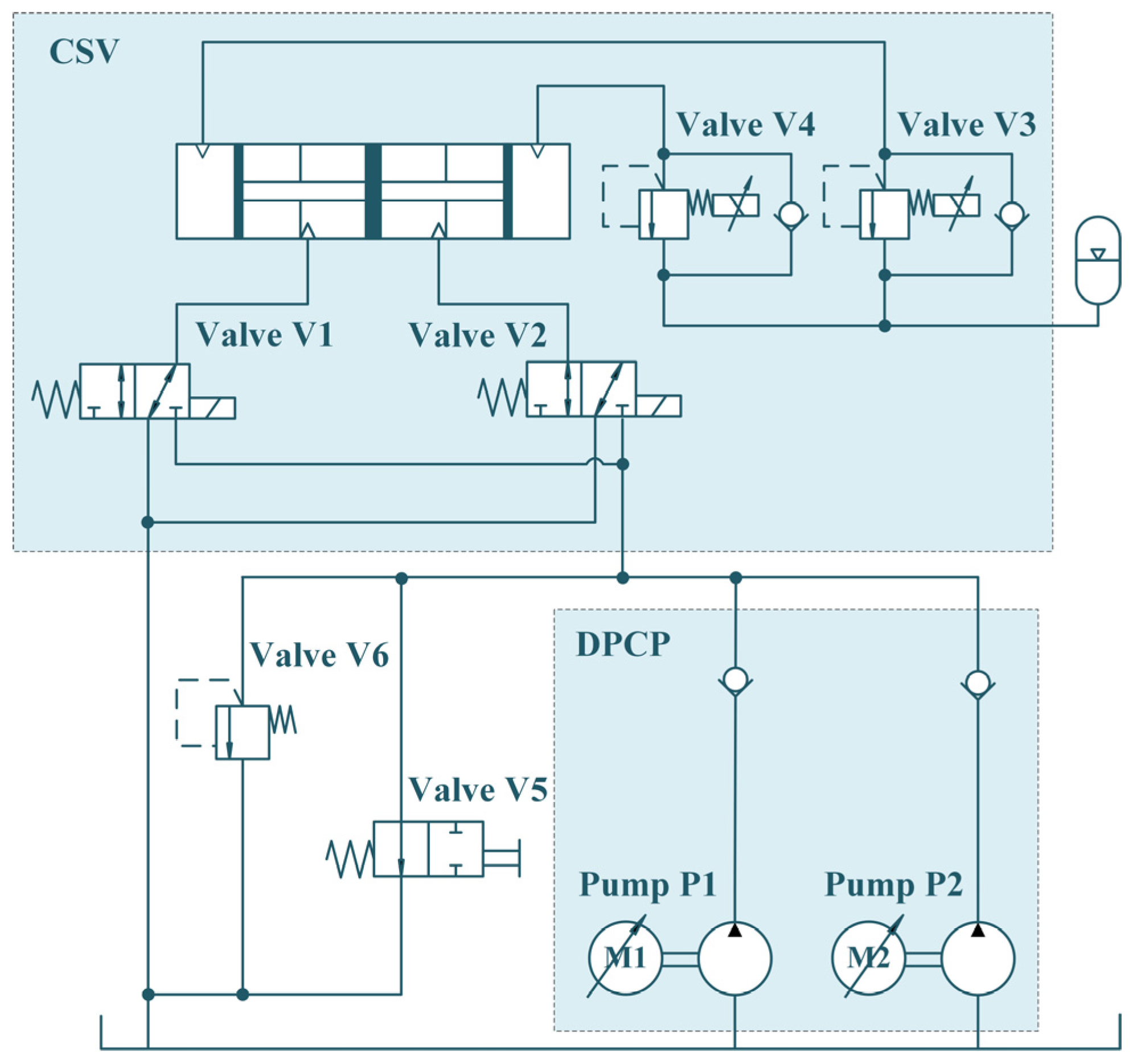
2. Design of Parallel-Connected-Pump Hydraulic System

Based on the objectives of high-accuracy tracking performance and simultaneous quick response, the DPCP hydraulic system is designed with two main parts, as shown in Figure 2. The dual parallel-connected-pump (DPCP) part contains two fixed-displacement pumps: a small one (P1) and a large one (P2). Their outlet flows are regulated by changing the rotation speed of the servo motor. The circuit switching valves (CSVs) include two switching valves, V1 and V2, and two proportional relief valves, V3 and V4. Specifically, V1 and V3 are connected to the right chamber of the hydraulic cylinder, and V2 and V4 are connected to the left chamber. The accumulator is the power source of the load on the hydraulic cylinder. In addition, switching valve V5 controls the pump unloading circuit, and relief valve V6 ensures safe operation.
The basic working principle divides the outlet flow into three stages, low, standard, and high, as shown in Figure 3. During the low-flow stage, only small fixed-displacement pump P1 works; therefore, quick response and high precision are satisfied. Only large fixed-displacement pump P2 works in the normal-flow stage due to its high gain. When in the high-flow stage, due to the slow dynamic response of P2, its outlet flow cannot achieve the expected tracking performance in the initial stage. In the subsequent stage, the outlet flow of P1 cannot satisfy the high-flow gain in segment positioning. Therefore, in this case, P2 supplies the majority of the desired flow, and P1 supplies the minority.

3. Comparative Experiments

Since P1 and P2 have their best-performance working area, the error distributed into each pump should be determined. Thus, the low flow range of P1 and the dead zone of P2 were refined by experiments. The test rig of the DPCP hydraulic system was built, as illustrated in Figure 4. Direction switching valves V1 and V2 were Parker DSH083B series 3-way spool valves. The Beinlich ZPD-type fixed-displacement pumps driven by the servo motor were implemented in the pump station. The normal accumulator pressure was 2 bar, and the total volume was 0.32 dm3. The proposed method was tested by controlling the piston position of the industrial single-rod hydraulic cylinder to track the position reference trajectory. The piston and rod diameters of the hydraulic cylinder were 90 mm and 63 mm, respectively. The piston position was measured by the MTS company FHTA19 series sensor with an analog measurement resolution of about ±0.25 mm. The real-time controller was a National Instruments cRIO 9034. LabVIEW ™ was used as the software environment, which was constructed by the Real Time (control flow), VISA (serial communication), and FPGA (real-time data sampling and filtering) Modules.
In the flow test of pump P2, the time interval of the P2 slow-started phase was about 2 s, which was partially compensated by pump P1. During this phase, P2 outputted a small part of the desired flow, and P1 outputted most of the desired flow. After that, when entering the flow stabilization period, P1 switched to a low-outlet-flow state, and P2 switched to a high-outlet-flow state. Thus, several sets of motion-tracking experiments were performed to verify a suitable flow limit to start the error allocation strategy, including the ramp curve with a velocity from 1 mm/s to 12 mm/s. Two comparative methods were first applied as follows.
C1: The small direct fixed-displacement pump controlled the hydraulic cylinder directly through the switching valves. The PID parameters were P1 = 785, I1 = 0.13, and D1 = 0.0014.
C2: The large direct fixed-displacement pump controlled the hydraulic cylinder directly through the switching valves. The PID parameters were P2 = 555, I2 = 0.003, and D2 = 0.0005.
Firstly, for the ramp curve with a velocity from 1 mm/s to 6 mm/s, the tracking performance comparisons in the two sets of experiments are shown in Figure 5, and a numerical comparison is provided in Table 1 for more in-depth analysis. Overall, C1 and C2 both achieved high tracking precision when tracking the slow-motion trajectories, especially when the velocity was less than 3 mm/s. C1 allowed for a relatively stable and linear outlet flow compared with C2, with its controllable minimum flow and low inertia, whether in the startup phase or the stable tracking phase. However, as the flow rate increased, C1 needed to drive a large flow output at a higher motor speed. Therefore, during the startup phase, the overshoot of C1 increased significantly. Moreover, due to the controllable minimum displacement and the high inertia of C2, its callback time after overshoot was longer, causing its tracking error to exhibit a sinusoidal signal.
Moreover, when the velocity reached 7 mm/s, the tracking performance of C1 and C2 was not very different. Once the flow reached 8 mm/s, C1 could not converge to a smaller tracking error. The same was true for C2, which showed obvious flow rate fluctuations. In this case, it is necessary to allocate the tracking error into C1 and C2, thereby compensating for the response speed and dynamic performance of C2. Another comparative method was applied as follows.
C3: The small fixed-displacement pump and large fixed-displacement pump controlled the hydraulic cylinder directly through the switching valves. The PID parameters were the same as in C1 and C2.
Initially, the error allocation proportion was set to k1:k2 = 9:1 to compensate for the dead zone and slow dynamics of P2. Afterward, when the flow entered a stable stage, considering the divergence of small-pump flow tracking, the error allocation proportion was set to k1:k2 = 4:6. The mode switching timestamp was set to T = 2 s. Figure 6 and Table 2 present the performance comparisons and numerical comparisons, respectively. At an expected tracking velocity of 7 mm/s, C1 required approximately 8 s to converge the error, whereas C2 exhibited more significant oscillation. At a velocity of 8 mm/s, C1 exhibited control divergence, while the oscillations under C2 control became more pronounced, resulting in a maximum tracking error of 8.597 mm. This was the moment to transition to DPCP control mode. It is essential to distribute the tracking error between C1 and C2 to account for the response speed and dynamic performance of C2. The comparative method was applied in the following manner. Figure 7 and Table 3 present the performance comparisons between C2 and C3. C3 successfully satisfied the control requirement of normal flow, demonstrating the effectiveness of the proposed DPCP system controller in managing a wide flow range.

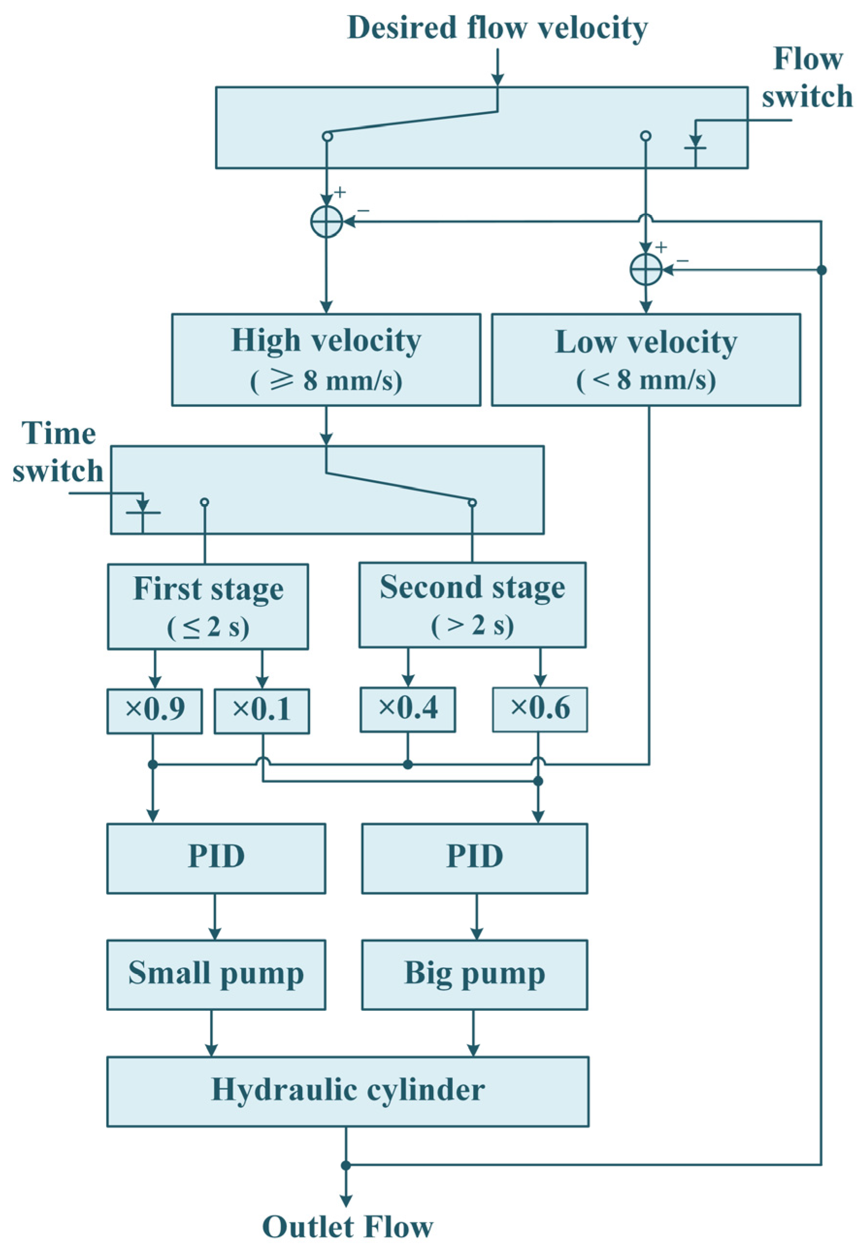
4. Two-Level Error Allocation Strategy

Based on the DPCP principle and the error allocation strategy, the influence of the allocation proportion and the switching timestamp on motion performance is further analyzed. Aiming at the high flow of a velocity of 9 mm/s to 12 mm/s, three comparative methods for allocation proportion were applied as follows.
A1: Mode switching timestamp T = 2 s. Error allocation proportions k1:k2 = 1:9 before switching and k1:k2 = 3:7 after switching.
A2: Mode switching timestamp T = 2 s. Error allocation proportions k1:k2 = 1:9 before switching and k1:k2 = 4:6 after switching.
A3: Mode switching timestamp T = 2 s. Error allocation proportions k1:k2 = 1:9 before switching and k1:k2 = 5:5 after switching.
A comparison of the tracking errors is illustrated in Figure 8, and a numerical comparison is listed in Table 4 for more in-depth analysis. The results presented in Figure 8 primarily address the role of the error allocation proportion. In comparison to the experimental results observed during the low-velocity phase, C3 encountered challenges in achieving reduced overshoot during the startup phase. In instances of high velocity, prior to the alteration in the error proportion, the flow was predominantly supplied by the small pump. At a velocity of 8 mm/s, the tracking error of the small pump surpassed 4 mm at 2 s, while the overshoot of the large pump at the same time approached 8 mm. The two points indicate that achieving lower overshoot in control mode C3 is impossible. The error allocation proportion after 2 s indicates that a greater allocation to the small pump will result in its divergence being evident. Increased allocation to the large pump will result in the manifestation of its high oscillation characteristics. Both factors influenced motion stability and tracking accuracy after 2 s. Consequently, this chapter introduces only three error allocation proportions: 3:7, 4:6, and 5:5. The curves presented in Figure 8 exhibit a similar trend. After 2 s, the motion smoothness and steady-state error of A2 were marginally superior to those of the other two systems. The error allocation ratio of 4:6 optimally enhanced the flow correction capability of the small pump and the rapid response capacity of the large pump. The reduced setting time indicates that A2 can complete a wide range of segment positioning more quickly and transition to the attitude fine-tuning phase sooner.
Furthermore, aiming at 9 mm/s to 12 mm/s, three comparative methods on the switching timestamp were applied.
S1: Mode switching timestamp T = 1 s. Error allocation proportions k1:k2 = 1:9 before switching and k1:k2 = 4:6 after switching.
S2: Mode switching timestamp T = 2 s. Error allocation proportions k1:k2 = 1:9 before switching and k1:k2 = 4:6 after switching.
S3: Mode switching timestamp T = 3 s. Error allocation proportions k1:k2 = 1:9 before switching and k1:k2 = 4:6 after switching.
Figure 9 and Table 5 present findings that primarily address the impact of switching time on tracking performance. The experiments on the allocation proportion indicate that a 4:6 allocation ratio is optimal. The subsequent aspect to investigate is the switching time of the error allocation ratio. It is directly related to whether flow control can be carried out as early as possible with a 4:6 error distribution ratio, which has a significant impact on the subsequent tracking performance. Nonetheless, the general trend of the curve remains largely consistent. The insufficient flow of the small pump, combined with the slow start of the large pump, resulted in a noticeable lag in the flow output of C3. In each set of comparative experiments, the optimal lag duration and maximum error occurred at a switching time of 2 s, which also yielded the smallest steady-state error. Switching to an allocation ratio of 4:6 prematurely resulted in marginally extended overshoot recovery time and adjustment period. This indicates that utilizing the large pump as the primary component of the output flow prematurely adversely impacts the tracking performance due to its significant oscillation characteristics. Delaying the transition to a 4:6 allocation ratio resulted in an increased steady-state error. This indicates that the divergence characteristics of the small pump will impact the tracking performance if it is utilized as the primary component of the output flow for an extended period of time. Overall, the numerical results indicate that the difference between the average tracking error and the maximum tracking error remained minimal as the velocity increased from 9 mm/s to 12 mm/s, with the maximum not exceeding 1 mm. The tracking performance showed the greatest improvement when the switching time was set to 2 s.
According to the above experiments, the optimal switching timestamp was chosen as T = 2 s, and the allocation proportions were set to k1:k2 = 1:9 before switching and k1:k2 = 4:6 after switching. Aiming at the velocity of 9 mm/s to 12 mm/s, a comparison of the tracking errors between C2 and C3 is illustrated in Figure 10, and a numerical comparison is listed in Table 6 for more in-depth analysis. Figure 10 presents the tracking performance of C3 following the determination of the optimal error allocation proportion and switching time. As the velocity increased, the displacement of the hydraulic cylinder in mode C2 exhibited greater oscillation, with the maximum displacement error reaching 17.728 mm at a velocity of 12 mm/s. During the segment positioning stage, overshoot can pose significant safety risks, including segment collisions resulting from overtravel. The prolonged adjustment period resulted in a delayed attainment of the attitude fine-tuning stage. In control mode C3, at the velocities of 9 mm/s and 10 mm/s, the tracking error converged to 0 in approximately 2 s. The maximum adjustment time did not surpass 3 s. The average tracking error demonstrates that as the velocity increased, C3 exhibited a more significant improvement compared with C2. The enhancement at 12 mm/s was approximately sixfold. Conversely, the improvement effect of the maximum error diminished with the increase in velocity. The effectiveness of the DPCP system and error allocation in dealing with high flow was confirmed.

5. Conclusions

The main contributions of this paper are the development of the DPCP hydraulic system, the hardware configurations and working principles, the idea of the error allocation strategy solving the low–normal–high-flow control problems, and the experimental validation showing the advantages of the proposed system for segment assembly in large-diameter TBMs. The paper proposed a novel electro-hydraulic system that combines two fixed-displacement pumps to achieve high precision and quick response motion tracking in the entire flow domain. The basic working principles are the following: the small fixed-displacement pump is controlled with PID to provide the smaller amount of flow driving the segment erector in a quick-start or highly precise way; then, the large fixed-displacement pump guarantees the tracking performance by supplying the majority of the amount of flow in large flow. The error allocation strategy with the DPCP system was designed to handle the challenges of not only quick and precision motion control of the hydraulic cylinder but also additional flexibility brought by the hardware combination. Several sets of comparative experiments were performed to show the advantages of the proposed system. Future work will focus on implementing self-adaptive error allocation to optimize flow-tracking performance.

Author Contributions

Conceptualization, L.J. and Z.Z.; methodology, L.J. and Z.Z.; software, K.Z. and Z.Z.; funding acquisition, D.H.; writing—original draft preparation, L.J. and Z.Z.; writing—review and editing, L.J. and Z.Z.; project administration, G.G. and H.Y. All authors have read and agreed to the published version of the manuscript.

Funding

This research was funded by National Key Research and Development Program of China, grant number 2022YFC3802302.

Data Availability Statement

The data that support the findings of this study are available from the corresponding author upon reasonable request.

Conflicts of Interest

Author Lijie Jiang was employed by the company China Railway Engineering Equipment Group Co., Ltd. The remaining authors declare that the research was conducted in the absence of any commercial or financial relationships that could be construed as a potential conflict of interest.

References

  1. Hong, K.R.; Du, Y.L.; Kui, C.; Feng, H.H.; Jia, L.H.; Xu, F. Full-face tunnel boring machines (Shields/TBMs) in China: History, achievements, and prospects. Tunn. Constr. 2022, 42, 739–756. (In Chinese) [Google Scholar]
  2. Zheng, Z.; Luo, K.D.; Tan, X.Z.; Jia, L.H.; Xie, M.R.; Xie, H.B.; Jiang, L.J.; Gong, G.F.; Yang, H.Y.; Han, D. Autonomous steering control for tunnel boring machines. Autom. Constr. 2024, 159, 105259. [Google Scholar] [CrossRef]
  3. Zheng, Z.; Wang, F.; Gong, G.F.; Yang, H.Y.; Han, D. Intelligent technologies for construction machinery using data-driven methods. Autom. Constr. 2023, 147, 104711. [Google Scholar] [CrossRef]
  4. Lyu, L.; Liang, X.; Guo, J. Synchronization Control of a Dual-Cylinder Lifting Gantry of Segment Erector in Shield Tunneling Machine under Unbalance Loads. Machines 2021, 9, 152–174. [Google Scholar] [CrossRef]
  5. Li, Y.S.; Sun, Q.; Zhang, L.M.; Wang, Z.Y.; Feng, W.Q. Online multi-objective optimization for tunnel boring machine segment assembly considering stress concentration. Autom. Constr. 2023, 156, 105127. [Google Scholar] [CrossRef]
  6. Zhang, W.J.; Yang, Y.; Zhang, C.; Zhang, G.L.; He, L.C.; Lyu, J.R. Dynamic Autonomous Deviation Correction of Super-large Diameter Shield Tunnel Rings Based on Multi-objective Control Techniques. China J. Highw. Transp. 2023, 36, 231–234. [Google Scholar]
  7. Liu, C.Y.; Wu, J.; Jiang, X.L.; Gu, Y.F.; Xie, L.Q.; Huang, Z.R. Automatic assembly of prefabricated components based on vision-guided robot. Autom. Constr. 2024, 162, 105385. [Google Scholar] [CrossRef]
  8. Tshimbombo, T.; Perry, M.; Dow, H.; McAlorum, J.; Hoy, C.; Litina, C. Automated Manufacturing of tunnel segment. In Proceedings of the Conference on Sensors and Smart Structures Technologies for Civil, Mechanical, and Aerospace Systems, Long Beach, CA, USA, 13–16 March 2023. [Google Scholar]
  9. Du, C.D.; Du, Y.H.; Huang, X.F. Control Technology for Segment Dislocation and Attitude of Large-Diameter Shield Tunnels. Tunn. Constr. 2024, 44, 1510–1519. (In Chinese) [Google Scholar]
  10. Xie, P.; Chen, K.; Zhu, Y.; Luo, H. Dynamic parametric modeling of shield tunnel: A WebGL-based framework for assisting shield segment assembly point selection. Tunn. Undergr. Space Technol. 2023, 142, 105395. [Google Scholar] [CrossRef]
  11. Hu, M.; Sun, J.C.; Wu, B.J.; Wu, H.M.; Xu, Z.J. Shield Tunnel (Segment) Uplift Prediction and Control Based on Interpretable Machine Learning. Sustainability 2024, 16, 910. [Google Scholar] [CrossRef]
  12. Zheng, M.; Lan, M.; Zhu, C.L.; Lin, D.S.; Zhang, W.H. Overall Design for a Tunnel Segment Assembly System of Shield Machine Based on Virtual Reality Technology. In Proceedings of the 2019 IEEE International Conference on Architecture, Construction, Environment and Hydraulics (ICACEH), Xiamen, China, 20–22 December 2019. [Google Scholar]
  13. Guo, W.T.; Guo, W.Z.; Gao, F.; Mo, P.X. Innovative Group-Decoupling Design of a Segment Erector Based on GF Set Theory. Chin. J. Mech. Eng. 2013, 26, 264–274. [Google Scholar] [CrossRef]
  14. Yuan, Y.C.; Zhang, Y. Building of Fine-tuning Mechanism Posture and Kinematics Model for Shield Segment Erector. In Proceedings of the 2nd International Conference on Chemical, Material and Metallurgical Engineering (ICCMME 2012), Kunming, China, 15–16 December 2013. [Google Scholar]
  15. Wang, L.; Gong, G.; Yang, H.; Yang, X.; Hou, D. The Development of a High-Speed Segment Erecting System for Shield Tunneling Machine. IEEE ASME Trans. Mechatron. 2013, 18, 1713–1723. [Google Scholar] [CrossRef]
  16. Cui, G.; Zhang, D.; Zhou, H.; Zhang, Y. Operating dexterity optimization and analysis of a 3-DOF parallel manipulator for a tunnel segment assembly system. Int. J. Mech. Mater. Des. 2015, 11, 277–285. [Google Scholar] [CrossRef]
  17. Sun, H.; Tao, J.F.; Qin, C.J.; Dong, C.; Xu, S.; Zhuang, Q.W.; Liu, C.L. Multi-objective trajectory planning for segment assembly robots using a B-spline interpolation- and infeasible-updating non-dominated sorting-based method. Appl. Soft Comput. 2024, 152, 111216. [Google Scholar] [CrossRef]
  18. Zhang, Y.W.; Wei, B.; Cui, G.H.; Wang, N. Local Stiffness and Dexterity Analysis of a 3-SPS-S Orientation Fine-Tuning Manipulator for Segment Assembly Robots in Shield Tunneling Machines. Appl. Mech. Mater. 2012, 128, 904–908. [Google Scholar] [CrossRef]
  19. Shi, H.; Gong, G.; Yang, H. Drive system design and error analysis of the 6 degrees of freedom segment erector of shield tunneling machine. Front. Mech. Eng. 2011, 6, 369. [Google Scholar] [CrossRef]
  20. Zyada, Z.; Hasegawa, Y.; Fukuda, T. Multi-directional assembly of tunnel segments using a force controlled parallel link robot with fuzzy compensation. In Proceedings of the SICE 2003 Annual Conference (IEEE Cat. No.03TH8734), Fukui, Japan, 4–6 August 2003. [Google Scholar]
  21. Sun, W.; Du, J.N.; Wang, L.T.; Ma, H.H. High speed and low impact control method for electro-hydraulic system of segment erector in tunnel boring machine. J. Zhejiang Univ. Eng. Sci. 2017, 51, 1948–1958. (In Chinese) [Google Scholar]
  22. Zhou, Y.; Wang, Y.; Ding, L.; Love, P.E.D. Utilizing IFC for shield segment assembly in underground tunneling. Autom. Constr. 2018, 93, 178–191. [Google Scholar] [CrossRef]
  23. Kosuge, K.; Takeo, K.; Taguchi, D.; Fukuda, T.; Murakami, H. Task-oriented force control of parallel link robot for the assembly of segments of a shield tunnel excavation system. IEEE ASME Trans. Mechatron. 1996, 1, 250–258. [Google Scholar] [CrossRef]
  24. Wei, Q.; Tao, J.F.; Sun, H.; Liu, C.L. Mechanism Surrogate Based Model Predictive Control of Hydraulic Segment Assembly Robot with Sliding Friction. In Proceedings of the Intelligent Robotics and Applications, Hangzhou, China, 6 October 2023. [Google Scholar]
  25. Sun, H.; Tao, J.F.; Qin, C.J.; Yu, H.G.; Xu, S.; Zhuang, Q.W.; Liu, C.L. Optimal Energy Consumption and Response Capability Assessment for Hydraulic Servo Systems Containing Counterbalance Valves. J. Mech. Des. 2023, 145, 053501. [Google Scholar] [CrossRef]
  26. Sun, H.; Tao, J.F.; Qin, C.J.; Yu, H.G.; Liu, C.L. Dynamics Modeling and Bifurcation Analysis for Valve-Controlled Hydraulic Cylinder System Containing Counterbalance Valves. J. Vib. Eng. Technol. 2021, 9, 1941–1957. [Google Scholar] [CrossRef]
  27. Li, M.J.; Wei, J.H.; Fang, J.H.; Shi, W.Z.; Guo, K. Fuzzy impedance control of an electro-hydraulic actuator with an extended disturbance observer. Front. Inf. Technol. Electron. Eng. 2019, 20, 1221–1233. [Google Scholar] [CrossRef]
  28. Li, M.J.; Shi, W.Z.; Wei, J.H.; Fang, J.H.; Guo, K.; Zhang, Q. Parallel Velocity Control of an Electro-Hydraulic Actuator With Dual Disturbance Observers. IEEE Access 2019, 7, 56631–56641. [Google Scholar] [CrossRef]
  29. Long, M.; Hu, A.M.; Gao, Z.G.; He, X.J. Velocity and Load Characteristics Analysis of Pump-Control-Motor Hydraulic Drive System. In Proceedings of the International Conference on Manufacturing Engineering and Automation, Guangzhou, China, 7–9 December 2011. [Google Scholar]
  30. Zhu, T.; Xie, H.; Yang, H. Design and tracking control of an electro-hydrostatic actuator for a disc cutter replacement manipulator. Autom. Constr. 2022, 142, 104480. [Google Scholar] [CrossRef]
  31. Xiang, Y.S.; Li, R.Y.; Brach, C.; Liu, X.L.; Geimer, M. A Novel Algorithm for Hydrostatic-Mechanical Mobile Machines with a Dual-Clutch Transmission. Energies 2022, 15, 2095. [Google Scholar] [CrossRef]
  32. Xiang, Y.S.; Mutschler, S.; Brix, N.; Brach, C.; Geimer, M. Optimization of hydrostatic-mechanical transmission control strategy by means of torque control. In Proceedings of the 12th International Fluid Power Conference, Dresden, Germany, 12–14 October 2020. [Google Scholar]
  33. Mutschler, S.; Brix, N.; Xiang, Y.S. Torque Control for Mobile Machines. In Proceedings of the 11th International Fluid Power Conference, Aachen, Germany, 19–21 March 2018. [Google Scholar]
  34. Helian, B.B.; Chen, Z.; Yao, B. Precision Motion Control of a Servomotor-Pump Direct-Drive Electrohydraulic System With a Nonlinear Pump Flow Mapping. IEEE Trans. Ind. Electron. 2020, 67, 8638–8648. [Google Scholar] [CrossRef]
  35. Chen, Z.; Helian, B.B.; Zhou, Y.; Geimer, M. An integrated trajectory planning and motion control strategy of a variable rotational speed pump-controlled electro-hydraulic actuator. IEEE ASME Trans. Mechatron. 2022, 28, 588–597. [Google Scholar] [CrossRef]
  36. Lin, X.Z.; Xu, J.; Yu, J.C.; Zhang, X.L.; Zheng, Y.L.; Li, S.; Du, H. High-performance steering tracking control of open circuit variable-speed pump-controlled steering system for heavy-duty vehicles based on flow nonlinearity compensation. Proc. Inst. Mech. Eng. Part D J. Automob. Eng. 2024, 1–20. [Google Scholar] [CrossRef]
Figure 1. Main process of building tunnel lining. (a) General structure of a tunnel and a TBM. (b) Segment erector in the actual project. (c) Typical structure of a segment erector.
Machines 12 00913 g001
Figure 2. Configuration of DPCP hydraulic system.
Machines 12 00913 g002
Figure 3. Structure of basic working principle.
Machines 12 00913 g003
Figure 4. Test rig of DPCP hydraulic system.
Machines 12 00913 g004
Figure 5. Comparison of tracking performance (tracking error) at low flow velocity: (a) C1 and C2 at velocity of 1 mm/s; (b) C1 and C2 at velocity of 2 mm/s; (c) C1 and C2 at velocity of 3 mm/s; (d) C1 and C2 at velocity of 4 mm/s; (e) C1 and C2 at velocity of 5 mm/s; (f) C1 and C2 at velocity of 6 mm/s.
Machines 12 00913 g005
Figure 6. Comparison of tracking performance (tracking error) at normal flow velocity: (a) C1 and C2 at velocity of 7 mm/s; (b) C1 and C2 at velocity of 8 mm/s.
Machines 12 00913 g006
Figure 7. Comparison of C2 and C3 tracking performance (tracking error) at velocity of 8 mm/s.
Machines 12 00913 g007
Figure 8. Comparison of tracking performance (tracking error) with different allocation proportions: (a) A1, A2, and A3 at velocity of 9 mm/s; (b) A1, A2 and A3 at velocity of 10 mm/s; (c) A1, A2 and A3 at velocity of 11 mm/s; (d) A1, A2 and A3 at velocity of 12 mm/s.
Machines 12 00913 g008
Figure 9. Comparison of tracking performance (tracking error) with different switch timestamps: (a) S1, S2, and S3 at velocity of 9 mm/s; (b) S1, S2 and S3 at velocity of 10 mm/s; (c) S1, S2 and S3 at velocity of 11 mm/s; (d) S1, S2 and S3 at velocity of 12 mm/s.
Machines 12 00913 g009
Figure 10. Comparison of tracking performance (tracking error): (a) C2 and C3 at velocity of 9 mm/s; (b) C2 and C3 at velocity of 10 mm/s; (c) C2 and C3 at velocity of 11 mm/s; (d) C2 and C3 at velocity of 12 mm/s.
Machines 12 00913 g010
Table 1. Numerical comparison of tracking errors at velocity from 1 mm/s to 6 mm/s.
Velocity (×mm/s)Methods‖e‖mean (×mm)‖e‖max (×mm)
1C10.1790.602
C20.4631.069
2C10.2771.175
C20.6071.496
3C10.3641.669
C20.6301.496
4C10.6031.957
C20.9331.978
5C10.4722.657
C21.1352.802
6C10.4672.657
C21.4923.985
Table 2. Numerical comparison of tracking errors at velocity from 7 mm/s to 8 mm/s.
Velocity (×mm/s)Methods‖e‖mean (×mm)‖e‖max (×mm)
7C11.7444.027
C22.3886.106
8C16.93310.421
C22.5598.597
Table 3. Numerical comparison of tracking errors at velocity of 8 mm/s.
Methods‖e‖mean (×mm)‖e‖max (×mm)
C16.93310.421
C22.5598.597
C31.4123.818
Table 4. Numerical comparison of tracking errors with different allocation proportions.
Velocity (×mm/s)Second Proportion‖e‖mean (×mm)‖e‖max (×mm)
9A11.5895.208
A21.0943.662
A31.9394.851
10A11.6144.807
A21.3524.540
A32.0115.036
11A11.9746.580
A21.5555.799
A32.4005.476
12A12.1678.054
A21.6997.007
A32.4528.690
Table 5. Numerical comparison of tracking errors with different switch timestamps.
Velocity (×mm/s)Switch Timestamp (×s)‖e‖mean (×mm)‖e‖max (×mm)
9S11.4034.104
S21.0943.662
S32.0054.314
10S11.6615.231
S21.3524.540
S31.9715.121
11S11.6036.047
S21.5555.799
S32.1476.770
12S12.0907.286
S21.6997.007
S32.0927.479
Table 6. Numerical comparison of tracking errors at velocity from 9 mm/s to 12 mm/s.
Velocity (×mm/s)Methods‖e‖mean (×mm)‖e‖max (×mm)
9C23.83510.352
C31.0943.662
10C24.74012.767
C31.3524.540
11C26.45714.818
C31.5555.799
12C29.82717.728
C31.6997.007
Disclaimer/Publisher’s Note: The statements, opinions and data contained in all publications are solely those of the individual author(s) and contributor(s) and not of MDPI and/or the editor(s). MDPI and/or the editor(s) disclaim responsibility for any injury to people or property resulting from any ideas, methods, instructions or products referred to in the content.

