1. Introduction
Smart manufacturing leverages advanced technologies—such as collaborative robots, artificial intelligence (AI), the Internet of Things (IoT), and data analytics [
1]. A critical component of this approach is quality inspection, which ensures product quality while minimizing the costs associated with rework, returns, and repairs. By integrating automated inspection processes, smart manufacturing enables real-time quality control, reduces reliance on manual inspection, and supports a responsive production environment that can adapt to changing demands and maintain high standards.
Inspection systems have received considerable attention in academic literature and widespread adoption among multinational corporations. However, there is slow adoption of these technological advancements by SMEs, despite the fact that they make up 90% of businesses globally [
1]. According to the published literature and current industry sentiment, SMEs worldwide face similar challenges in adapting to new technologies, which are summarized into three main barriers:
The cost barrier, entailing upfront capital investments and ongoing maintenance expenses [
2,
3];
The risk barrier, which involves introducing unfamiliar technologies into their core manufacturing processes that are potentially detrimental in the event of a malfunction [
4];
The complexity barrier, necessitating the upskilling or retraining of workers to implement new technologies [
5].
These barriers indicate a lack of introductory technologies that are low-cost, easy to use, and low-risk, leaving SMEs with two options: either continue with manual quality inspection or risk adopting complicated and expensive solutions with uncertain impacts on their productivity. Our work takes inspiration from the University of Cambridge’s Institute for Manufacturing “Digital Manufacturing on a Shoestring” methodology [
6]. This methodology places strong emphasis on understanding the unique requirements of each industry, paving the way for a smooth and successful digital transformation journey. This innovative approach empowers SMEs in the manufacturing sector by offering a suite of low-cost “starter kits” tailored to embrace and address the needs of SMEs in the same industry.
Building upon the shoestring methodology, this paper tackles the critical challenges: the cost, risk, and complexity barrier hindering the adoption of smart manufacturing technologies by SMEs. We present a novel and cost-effective quality inspection system and demonstrate its potential using a UPS chassis, showcasing the practical application of shoestring principles within the manufacturing environment by detecting the absence or mismatch in the shape, size, and color of features under inspection compared to flawless features. An easy-to-assemble structure incorporating 3D-printed components and standard industrial elements was designed; it also features low-cost electronics inspired by 3D printers with the corresponding firmware, and an adaptive, easy-to-train machine vision subsystem. Numerous quality inspection technologies, including ultrasonic testing, eddy current, thermography, X-ray, and visual inspection, have demonstrated substantial reliability in both research and industrial applications [
7,
8,
9,
10]. The proposed inspection system employs visual sensors, specifically a low-cost Raspberry Pi camera, to automate the quality inspection process. The aim is to also present an automated quality inspection system that assists SMEs in upskilling their workers, serving as a foundational step towards adopting intelligent manufacturing practices while keeping within a cost-effective developmental budget. This initiative is envisioned to encourage the exploration of smart manufacturing principles among SMEs, providing a tangible experience of the transformative potential inherent in such practices.
This paper is structured as follows:
Section 2 explores related work in general and low-cost visual inspection in manufacturing.
Section 3 discusses the concepts of a low-cost solution, including the criteria, scope, and architecture of a low-cost inspection system.
Section 4 details the implementation, covering its design requirements, inspection platform, actuation, sensing and machine vision, human–machine interface (HMI), and overall workflow design. Finally,
Section 5 presents the project’s outputs, and
Section 6 concludes the paper by discussing its anticipated impact on the manufacturing SME landscape.
2. Related Work
2.1. Visual Inspection Solutions in Manufacturing
There is an abundance of research and commercially available solutions on visual inspection in manufacturing. Ref. [
11] trained a convolutional neural network (CNN) model to inspect submersible pump impellers made of stainless steel. The model, trained with 6633 images, achieved an overall accuracy of 99.8% when evaluated on 715 images. Ref. [
12] combined log-Gabor filters, discrete wavelet transform, and discrete cosine transform features, fused using linear logistic regression, to inspect and classify solder joints in PCB manufacturing. Ref. [
13] implemented a machine vision system in a mask manufacturing plant to inspect defects in the nose wire fusion process and misalignment of the ear straps, resulting in a 61.1% increase in production speed and a 38% reduction in lead time per 100,000 masks. Ref. [
14] devised an inspection system to detect speckles and hair-like defects on molded pulp products using a combination of lightweight YOLOv5 and DeepLabV3Plus for improved accuracy. While these studies demonstrate promising accuracy and real-time inspection capabilities, they often face limitations. These include restrictions to a fixed angle from the top and the ability to only inspect small items. Moreover, the complexity and cost of replication present significant challenges for SMEs. Commercially available solutions, such as the Cognex In-Sight Vision System, Keyence Vision System, and Omron FH Series, also pose these three barriers for SMEs.
2.2. Current Low-Cost Solutions and Their Limitations
In response to these challenges, numerous approaches to low-cost inspection systems have been introduced. Ref. [
15] developed a moderately affordable visual inspection system for detecting defects on bolts, utilizing standard and accessible parts such as aluminum extrusions, a conveyor belt, servo motors, a stepper motor, and an Arduino Uno. Transfer learning was conducted using the VGG16 CNN model with 470 images to mitigate the complexity of training a CNN model from scratch, achieving 100% accuracy on 40 test data. Ref. [
16] built a quality inspection system based on DenseNet121 using transfer learning to inspect helical gears, training and validating the model with 4000 images on an NVIDIA GeForce GTX 1660Ti. The inspection algorithm demonstrated high accuracy at different resolutions. Ref. [
17] introduced a portable visual inspection system for detecting defects like cracks and pores in welding processes, using a Raspberry Pi microcomputer to reduce costs and promote portability. A machine learning algorithm based on a support vector machine was developed for defect classification. Ref. [
18] introduced a real-time inspection system for motor rotors using induced voltage caused by rotor spins. A residual multiscale feature fusion convolutional neural network was designed and trained using 180,000 images generated from the induced voltage signals for defect recognition and classification. The algorithm runs on a Raspberry Pi and achieves more than 99% accuracy when tested with 4000 images for each defect type. Ref. [
19] implemented a machine vision system to detect chips on piston rods, using transfer learning on pretrained CNN models. After two minutes of training on a laptop with 3000 images, the models were executable on a Raspberry Pi 3B+ microcomputer with an accuracy of over 90%. Previous research indicates that using a Raspberry Pi in combination with a Raspberry Pi camera provides sufficient computational capability for performing inspection tasks while significantly lowering the cost of computational platforms. To construct a DNN from scratch, a large amount of high-quality raw data is required, as well as labor-intensive and time-consuming data annotation. Additionally, high-computational-power GPUs are often necessary to accelerate the training process. The fine-tuning of learning parameters is needed to ensure the model achieves its optimal performance without overfitting or underfitting. Additional layer and neuron adjustments may be required depending on the model’s performance. It is impractical to believe that these limitations could be overcome by factory workers who lack engineering training. Transfer learning has been shown to reduce the complexity of employing deep neural networks (DNNs) while delivering high accuracy. This approach saves considerable time and reduces the computational resources required to train a sophisticated DNN from scratch. While it may be straightforward for engineers and researchers with prior knowledge and experience in training DNNs, it can still pose challenges for machine operators and personnel in SMEs who lack engineering training.
2.3. Resource-Friendly Machine Vision Solutions
In the pre-deep learning era, researchers focused on explicit feature extraction from images for defect detection. Ref. [
20] introduced an edge-based inspection approach for gears, calculating essential gear parameters and comparing them against nominal references as part of the defect detection process. Ref. [
21] proposed an edge-based approach considering various template image aspects, generating a likeness score for similarity assessment. Ref. [
22] used template matching to inspect the annular texture region of bottle bottoms in real time. Ref. [
23] applied template matching to identify number plates entering a campus car park and obtained an average accuracy of 80.8% by comparing the real number plate and the generated font style for template images.
While these conventional computer vision algorithms are susceptible to variations in ambient light and the orientation of objects relative to the camera, they do not require intensive training resources such as GPUs or a vast amount of data. Furthermore, they do not necessitate prior knowledge of DNNs or images of faulty features to maximize inspection accuracy, which are challenging to obtain in production settings.
3. Concept Design
3.1. Criteria for a Low-Cost Solution
Despite the innovative efforts made to introduce low-cost inspection solutions, several areas remain unclear and pose challenges for actual implementation and replication by SMEs. The definition of low cost remains obscure; some solutions, despite being labelled as cost-effective and more affordable than mature industrial alternatives, may still exceed the budget range of SMEs. The definition of “low-cost” should be context-dependent, varying with the complexity of the tasks being performed. Specifically, solutions that can replace more expensive commercially available products, or those that significantly reduce labor costs and enhance productivity, should have a higher acceptable budget compared to solutions that do not offer equivalent cost savings or productivity improvements.
Ref. [
24] attempted to address this issue for monitoring systems. Through conversations with numerous SMEs in the UK, they concluded that the total system cost for a monitoring system in a manufacturing context should be less than GBP 1000 (NZD 2170). Based on our experience working with local manufacturing partners in New Zealand, we believe that the budget of these systems should reflect the potential savings of further rework and inspections as well as additional replacement parts. Because of this, we estimate that a simple inspection system is considered low-cost if the total system cost is less than NZD 2000, while an inspection system capable of inspecting multiple features on different facets of a large object is considered low-cost if the total system cost is less than NZD 3000.
Ref. [
25] listed some criteria they believe a low-cost solution should satisfy, and we would like to expand on these. We believe the following criteria are essential for SMEs to practically adopt and deploy a low-cost design approach:
Accessible: The parts used in the design should ideally be off the shelf or should at least remain accessible to SMEs.
Easy to Replicate: The design should be simple to replicate, even for individuals with no prior engineering knowledge. A detailed and structured assembly guide, with incremental steps, should be provided.
Easy to Operate: The design should be easy to use for individuals with no prior engineering knowledge.
Easy to Maintain: The design should be easy to repair for individuals with no prior engineering knowledge.
Low-Risk: The design should be safe for construction, deployment, and long-term operation. It should avoid non-recoverable changes to existing devices or machines in a plant.
It is also worth noting that SMEs are generally interested in the return on investment (ROI) period of such solutions. They tend to favor low-cost solutions that provide easily quantifiable benefits and a quick ROI. For example, if a solution saves a specific amount of manual labor each week, SMEs can calculate how long it will take for that solution to generate savings or revenue that exceeds the initial capital or ongoing expenses.
3.2. Scope of a Low-Cost Inspection System
Inspection systems range from those that inspect small items or limited features at a fixed angle to those that inspect multiple features and facets of large objects with complex geometries. A comprehensive and generalized visual inspection system can be divided into two major stages, as depicted in
Figure 1: initialization and application.
The initialization stage can be further broken down into three sub-stages: construction, deployment, and training. Construction involves physically building the low-cost solution’s hardware and software. Deployment entails setting up a low-cost solution for functional operations. Training encompasses the initialization, adjustment, calibration, and finalization of the inspection algorithm.
The application stage can be divided into four sub-stages: actuation, sensing, analysis, and presentation. Actuation involves moving the object or sensor to an appropriate position for sensing. Sensing is the application stage at which the system captures raw data. Analysis refers to preprocessing the captured data and executing inspection algorithms. Presentation involves visualizing or providing information about the features or items under inspection.
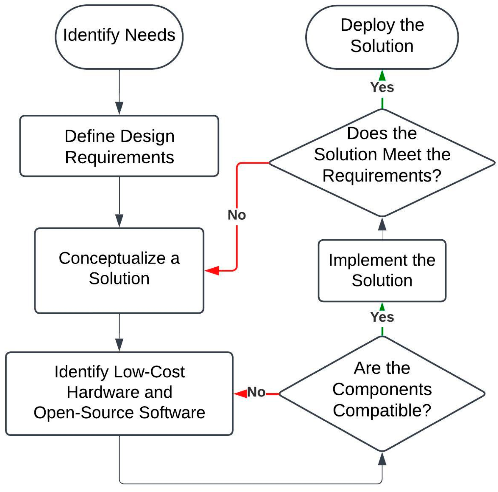
3.3. Low-Cost Inspection System Design Workflow
A workflow for developing a low-cost inspection system from scratch is illustrated in
Figure 2. The process begins with the identification of the specific inspection needs, such as whether the application requires visual inspection of multiple facets or simple distance detection at a fixed angle. Defining the design requirements is the next step and involves outlining the essential functionalities the system must fulfill to ensure accurate and reliable inspections that meet the expectations of SMEs. The conceptualization phase follows, involving the proposal of a practical and cost-effective engineering solution that satisfies these requirements by leveraging compatible and affordable components. After implementation, the system undergoes performance evaluation to assess whether it fulfills the previously defined requirements. If the system fails to meet these requirements, the workflow loops back to the conceptualization of a revised solution. Conversely, if the evaluation confirms that the system is effective, it is deemed ready for deployment.
3.4. Architecture of a Low-Cost Inspection System
Building upon the solution architecture laid out by the shoestring methodology [
6],
Figure 3 illustrates the authors’ proposal for the fundamental architecture more suited towards a visual inspection system. The system includes a mechanical inspection platform that physically moves the industrial parts under inspection or the sensing units themselves. The sensing unit, whether operating actively or passively, performs observations and monitors the status of the part under inspection, feeding data to a computational platform. This platform sends high-level commands to an actuation unit that drives motors, pneumatics, or hydraulic actuators, thereby moving the inspection platform. An HMI provides direct control over the actuation unit and inspection platform, as well as visualization of the inspection results.
3.5. The Proposed Workflow for a Low-Cost Inspection System
Referring back to
Figure 1, the
construct stage involves the physical assembly of the inspection platform, as well as the integration of the sensing units, actuation units, and computational platform. The
deploy stage includes the positioning of the industrial parts for inspection and the setting up of the other system components. During the
train stage, the HMI is used to configure the system, which may involve path planning or algorithm training, ensuring that all the prerequisites are met and that the inspection system is prepared for quality checks. In the
application stage, the computational platform sends commands to the actuation unit to move the part or the sensing unit for data capture. The sensing units collect the relevant data, which the computational platform then analyzes and visualizes on the HMI. This process is repeated, returning to the actuation stage as necessary, until the inspection process is complete.
4. Implementation
In this section, a novel inspection system is introduced using a UPS chassis as the application use case. The system is capable of inspecting numerous features on four facets of an object with complex geometry. This section sequentially covers the design requirements, inspection platform design, actuation design, machine vision, HMI, and overall workflow.
4.1. Design Requirements
Figure 4 illustrates the UPS chassis and its features, including rivets, rivet nuts, bolts, studs, and brackets. A camera is needed as the sensing unit to capture maximum details for accurate inspections. Given that SMEs manufacture various parts, a generalized inspection system should have the ability to learn what flawless features look like and to compare them with the current features under inspection. Any absence or mismatch in shape, color, and size would indicate that a faulty feature had been identified.
The chassis measures 717.5 mm in length, 630.35 mm in width, and 218 mm in height. This necessitates an inspection platform that can move the camera close to each feature for a close-up view. Additionally, the camera would need to travel vertically and horizontally to capture as many features as possible on one plane. Given that all six facets of the chassis have features on them, the inspection system should achieve more degrees of freedom. A rotational axis should be present to expose all four facets around the vertical axis of the chassis. The top and bottom facets of the chassis will not be inspected automatically but instead will be examined manually.
To mitigate the cost barrier, affordable and accessible actuation units are required; motors are one of them. It is also expected that a microcontroller would be used for low-latency and low-computational-power tasks, acting as the cerebellum of the system. An affordable and accessible microcomputer is needed for high-latency and high-computational-power tasks, which include path planning, image processing, and HMI.
4.2. Component Selection and Sourcing
The cost-effectiveness of low-cost inspection systems is inherently tied to the careful selection and sourcing of components. Ensuring affordability without compromising reliability requires the leveraging of widely available, off-the-shelf components and open-source software solutions. The proposed system prioritizes the use of commercially accessible technologies typically classified as “hobbyist” or maker-grade, which have demonstrated reliability in similar applications.
Table 1 provides examples of cost-effective technologies for each unit within the proposed architecture.
Component sourcing plays a critical role in ensuring the long-term viability and reproducibility of the proposed system. Centralized and reputable suppliers, such as DigiKey, Element14, and Mouser Electronics, have been identified as reliable sources due to their consistent quality and comprehensive inventories. For budget-constrained contexts, platforms such as AliExpress, Alibaba, and Taobao offer alternative sourcing options; however, careful verification of component authenticity and quality is essential when utilizing these suppliers.
4.3. Inspection Platform Design
Figure 5 illustrates the overall setup of the inspection system. The system comprises a 3-DoF gantry, which allows a camera payload to travel within an 850 mm × 850 mm × 600 mm volume, and a 1-DoF turntable where the item under inspection, in this case, a PEBB120 chassis, manufactured by an SME located in Christchurch, New Zealand, is placed. To mitigate cost barriers and promote accessibility, the structure of the mechanical assembly is constructed using easily sourced parts, such as aluminum extrusions, 3D-printed components made of polylactic acid (PLA), laser-cut acrylic parts, and plywood.
To keep the cost of the development of the system low, the design and assembly of the mechatronic subsystem was heavily inspired by the REPRAP method of developing low-cost 3D printers, which are in essence a 3-DoF gantry system with accessory axes. The system provides four independent degrees of freedom and enables the 360-degree inspection of the objects’ four facets placed on the turntable. This allows features to be seen at different yaw angles, providing an additional level of information by revealing hidden features, as well as providing confirmation on symmetry and uniformity. Firstly, the system incorporates a turntable to enable 360-degree rotation of the item under inspection about its yaw axis. The forward and backward movement of the camera payload, adjusting its distance from the chassis, operates as the y-axis using a rack and pinion linear actuator. The camera is capable of capturing images of features at various sizes. This movement is necessary because inspection objects with complex geometry may collide and cause damage to the system if the camera is not retracted while the object rotates. The side-to-side or left and right movement functions as the x-axis, and vertical movement, achieved through a synchronous timing belt-driven mechanism for enhanced torque and speed, serves as the z-axis. It is worth noting that these actuation axes can be disabled or removed depending on the requirements of inspection.
To facilitate transportation between different production lines, the lightweight properties of the components allow the system to be carried by a single person. Additionally, the support at the back of the system is designed to be foldable, enabling the entire assembly to be further compacted and to easily fit into the trunk of a medium-sized SUV to be moved between deployment sites.
4.4. Actuation Unit Design
An open-loop control system was used for actuation because it provided a sufficient level of repeatable precision and accuracy when used in conjunction with end-stop switching for positioning. Closed-loop systems necessitate the use of sensor-driven motors, like servo motors, or the application of encoders, which can make it significantly more expensive to achieve the desired torque specifications for the system. For this reason, the use of stepper motors, limit switches, and an open-loop control system was chosen as it offered repeatable and accurate actuation. The inspection system employs a total of five stepper motors: one NEMA17 motor for the
x-axis, one NEMA17 motor for the
y-axis, two NEMA17 motors for the
z-axis, and a NEMA23 motor for the turntable.
Figure 5 provides a detailed depiction of their connection and actuation mechanisms.
To achieve precise low-level control of the stepper motors, an affordable, accessible, and easily expandable microcontroller board is required. The Arduino Mega 2560 (manufactured in Pescara, Italy by Smart Projects (S.r.l), sourced from New Jersey, USA) was selected for this purpose due to its cost-effectiveness and expandability. It is paired with a RAMPS 1.4 expansion board (manufactured in Las Vegas, NV, USA by Polulu Corporation, sourced from China) and four DRV8825 stepper motor drivers (manufactured in Las Vegas, NV, USA by Polulu Corporation, sourced from China), each capable of delivering 2.2 A per coil, providing sufficient current for the stepper motors to drive the system on each individual axis. The compatibility of the Arduino Mega 2560 with the widely accessible open-source 3D printer firmware, Marlin, allows open-loop control by tailoring Marlin’s configurations to this specific application and mechanical structure. The electronics layout is shown in
Figure 6.
Figure 5f illustrates the actuation subsystem housed within an acrylic enclosure. The enclosure includes a Raspberry Pi 4B (manufactured by Raspberry Pi Holdings Ltd. in Pencoed, Wales, sourced from New Zealand), which handles high-level positioning tasks and connects to the Arduino Mega via a USB serial interface. Additionally, an AC to DC power supply unit, which converts 230 V from the mains to 12 V, is situated within the enclosure to power the system. We believe this feature affords the system operational flexibility, as it can be powered from any location with a standard AC mains connection.
4.5. Sensing and Machine Vision
DNNs combined with transfer learning have demonstrated great accuracy and require substantially fewer data compared to training a deep learning model from scratch. However, previous studies indicate that thousands of images are still required, which remains impractical for SMEs. To overcome this barrier, a conventional computer vision algorithm, template matching, was adopted. To enhance the generality of the algorithm, each template is compared against the others, generating a set of similarity scores. The mean of the similarity scores minus three times the standard deviation is used as the judging boundary. For inspection, each feature is compared against multiple template images; if the highest similarity score exceeds the threshold, the feature under inspection is deemed flawless.
A customized lighting solution is implemented to reduce the susceptibility to ambient light. As demonstrated in
Figure 4e,g, a ring light combined with a light shelter made of blinds is used to provide consistent illumination while blocking any potential ambient light changes, such as those caused by workers passing by or flickering ceiling lights. A camera is positioned at the center of the ring light, aligning the camera and the light’s illumination direction. To minimize glare from the ring light, particularly on the metallic surfaces of the chassis, which can hinder template matching, machine operators are instructed to take images at an angle for optimal inspection accuracy.
4.6. Human–Machine Interface Design
To address the complexity barrier, an intuitive graphical user interface (GUI) was developed using Tkinter (v8.6), a widely adopted library for GUI design in Python (v3.9.2), making it executable on a Raspberry Pi 4B. As depicted in
Figure 7, the GUI allows incremental control of its axes, enabling operators to click and drag a region of interest to include the feature they wish to inspect.
Figure 8 illustrates the overall architecture of the GUI, which employs multi-threading for image feed, inspection, and real-time communication between the Raspberry Pi and the Arduino Mega. The GUI makes use of object-oriented programing, multi-threading, and dequeue data structures to achieve a lightweight executable package, which is easily deployed and run on a Raspberry Pi OS.
4.7. Overall Workflow
Building upon the scope illustrated in
Figure 1,
Figure 9 illustrates the comprehensive scope of the proposed system.
Figure 10 outlines the detailed workflow of the proposed inspection system. The system requires multiple defect-free items for training to enhance the generalization capabilities of the machine vision algorithms. Initially, operators manually train the system by guiding the camera to desired locations via the UI to capture the critical features of the first defect-free item. This manual process establishes the baseline for the subsequent automated training. The system then autonomously trains on additional defect-free items, generating thresholds for various features. Upon completion of the training phase with a sufficient number of defect-free items, the system is ready for deployment in production environments. This training process ensures that the system is capable of accurately identifying defects by comparing new items against the established thresholds derived from the defect-free samples.
5. Evaluation
This section evaluates the performance of the system and assesses its effectiveness in mitigating the barriers for SMEs. The evaluation utilizes three distinctive features, as illustrated in
Figure 11. For each feature, 10 template images are used for training, followed by 20 inspections with slight variations in angle to maximize turbulence. Each set includes 10 inspections with flawless features and 10 with faulty features. The black horizontal line represents the threshold used for judgment. Upon initial testing the algorithm distinguished between flawless and faulty features with a 100% success rate within 10 training cycles. The system demonstrates the ability to perform inspections after a short training phase, facilitated by an intuitive and user-friendly GUI. This significantly reduces the complexity barrier by eliminating the need for expertise in collecting high-quality images, manual labelling, extended training times, GPU resources, and fine-tuning for deep neural networks.
Regarding the cost barrier, the total cost for this system is approximately NZD 2500 (USD ~1530), making it substantially more affordable than the existing solutions on the market. This effectively mitigates the cost barrier. Further details are provided in
Table 2.
We believe this work introduces a novel, introductory quality inspection system that enables SMEs to have a tangible experience of automated quality inspection, serving as a steppingstone for their journey into smart manufacturing. Additionally, this work empowers employees by enhancing their skillsets as they construct the system. We anticipate that they will learn about simple mechanical structures and understand how different systems are integrated and function together in concert.
6. Conclusions and Future Work
In this paper, a novel “starter-kit” for automating the inspection process of various industrial components is introduced. It is specifically designed for SMEs that are hindered by cost, risk, and complexity barriers associated with new technologies. The cost barrier is mitigated by using affordable, accessible hobbyist components and standard industrial components, bringing the total cost of the system to approximately NZD 2500. The risk barrier is addressed by implementing the system in non-critical manufacturing processes and allowing manual inspection processes to be set up in parallel with the inspection system; although quality inspection is important, an ineffective automated inspection system does not disrupt normal manufacturing operations. The complexity barrier is reduced by providing an easy-to-use and easy-to-train machine vision system, featuring a short training phase due to the adoption of conventional computer vision algorithms, and a detailed assembly guide. The results demonstrate the system’s potential to achieve accurate inspections after multiple training cycles. Additionally, constructing such a system empowers employees in SMEs by exposing them to engineering knowledge.
The system currently faces some challenges from strong glares caused by the perpendicular arrangement of the ring light, camera, and the features under inspection. This glare can severely affect the pixel values of the captured raw image and reduce inspection accuracy. This necessitates viewing angles of the features to be at slightly oblique angles.
Future work will focus on improving the actuation design of the system to increase inspection speed as well as on enabling the inspection of both the top and bottom facets. We foresee further enhancements to the algorithm to reduce susceptibility to ambient light, potentially eliminating the need for a light shelter.
Author Contributions
Writing—original draft, H.S. and W.-T.T.; methodology, H.S. and W.-T.T.; writing—review and editing, H.S., W.-T.T., J.P. and X.X.; investigation, H.S., W.-T.T., K.W. and B.D.; data curation, H.S. and W.-T.T.; software, H.S. and B.D.; visualization, W.-T.T. and K.W.; conceptualization, J.P.; resources, X.X.; supervision, J.P. and X.X. All authors have read and agreed to the published version of the manuscript.
Funding
This research was partially funded by ABB Limited Napier.
Data Availability Statement
The data presented in this study are available on request from the corresponding author due to privacy concerns of ABB.
Acknowledgments
This work was supported by ABB Limited Napier, and the authors would like to express their gratitude for the ongoing collaboration and valuable industry insights. Furthermore, we would like to acknowledge the help of Trishit Ghatak regarding choosing the ideal hardware and sourcing the components.
Conflicts of Interest
The authors declare no conflicts of interest.
References
- Thorgren, S.; Williams, T.A. Staying alive during an unfolding crisis: How SMEs ward off impending disaster. J. Bus. Ventur. Insights 2020, 14, e00187. [Google Scholar] [CrossRef]
- Mittal, S.; Khan, M.A.; Romero, D.; Wuest, T. A critical review of smart manufacturing & Industry 4.0 maturity models: Implications for small and medium-sized enterprises (SMEs). J. Manuf. Syst. 2018, 49, 194–214. [Google Scholar] [CrossRef]
- Kumar, R.; Singh, R.K.; Dwivedi, Y.K. Application of industry 4.0 technologies in SMEs for ethical and sustainable operations: Analysis of challenges. J. Clean. Prod. 2020, 275, 124063. [Google Scholar] [CrossRef] [PubMed]
- Kumar, P.; Bhamu, J.; Sangwan, K.S. Analysis of Barriers to Industry 4.0 adoption in Manufacturing Organizations: An ISM Approach. Procedia CIRP 2021, 98, 85–90. [Google Scholar] [CrossRef]
- Ellingrud, K.; Gupta, R.; Salguero, J.; Building the Vital Skills for the Future of Work in Operations. McKinsey & Company. 2020. Available online: https://www.mckinsey.com/capabilities/operations/our-insights/building-the-vital-skills-for-the-future-of-work-in-operations#/ (accessed on 5 April 2024).
- McFarlane, D.; Ratchev, S.; Thorne, A.; Parlikad, A.K.; de Silva, L.; Schönfuβ, B.; Hawkridge, G.; Terrazas, G.; Tlegenov, Y. Digital Manufacturing on a Shoestring: Low Cost Digital Solutions for SMEs. In Proceedings of the Service Oriented, Holonic and Multi-Agent Manufacturing Systems for Industry of the Future (SOHOMA 2019), Valencia, Spain, 3–4 October 2019; Springer: Cham, Switzerland, 2020; Volume 853. [Google Scholar] [CrossRef]
- Ebayyeh, A.A.R.M.A.; Mousavi, A. A Review and Analysis of Automatic Optical Inspection and Quality Monitoring Methods in Electronics Industry. IEEE Access 2020, 8, 183192–183271. [Google Scholar] [CrossRef]
- Nascimento, R.; Martins, I.; Dutra, T.A.; Moreira, L. Computer Vision Based Quality Control for Additive Manufacturing Parts. Int. J. Adv. Manuf. Technol. 2023, 124, 3241–3256. [Google Scholar] [CrossRef]
- Papavasileiou, A.; Michalos, G.; Makris, S. Quality control in manufacturing—Review and challenges on robotic applications. Int. J. Comput. Integr. Manuf. 2024, 1–37. [Google Scholar] [CrossRef]
- Chen, Y.; Peng, X.; Kong, L.; Dong, G.; Remani, A.; Leach, R. Defect inspection technologies for additive manufacturing. Int. J. Extrem. Manuf. 2021, 3, 022002. [Google Scholar] [CrossRef]
- Sundaram, S.; Zeid, A. Artificial Intelligence-Based Smart Quality Inspection for Manufacturing. Micromachines 2023, 14, 570. [Google Scholar] [CrossRef]
- Mar, N.S.S.; Yarlagadda, P.K.D.V.; Fookes, C. Design and development of automatic visual inspection system for PCB manufacturing. Robot. Comput.-Integr. Manuf. 2011, 27, 949–962. [Google Scholar] [CrossRef]
- Park, M.; Jeong, J. Design and Implementation of Machine Vision-Based Quality Inspection System in Mask Manufacturing Process. Sustainability 2022, 14, 6009. [Google Scholar] [CrossRef]
- Wang, H.; Shi, Z.; Qiao, Y.; Yang, F.; He, Y.; Xuan, D.; Zhao, W. Autonomous and Cost-effective Defect Detection System for Molded Pulp Products. In Proceedings of the ACM/IEEE 14th International Conference on Cyber-Physical Systems (with CPS-IoT Week 2023), San Antonio, TX, USA, 9–12 May 2023; pp. 1–11. [Google Scholar] [CrossRef]
- Shih, Y.; Kuo, C.-C.; Lee, C.-H. Low-Cost Real-Time Automated Optical Inspection Using Deep Learning and Attention Map. Intell. Autom. Soft Comput. 2023, 35, 2087–2099. [Google Scholar] [CrossRef]
- Najah, A.; Mustafa, F.F.; Hacham, W.S. Building a High Accuracy Transfer Learning-Based Quality Inspection System at Low Costs. Al-Khwarizmi Eng. J. 2021, 17, 1–12. [Google Scholar] [CrossRef]
- Gong, Y.; Lin, Z.; Wang, J.; Gong, N. Bringing Machine Intelligence to Welding Visual Inspection: Development of Low-Cost Portable Embedded Device for Welding Quality Control. Electron. Imaging 2018, 30, 279-1–279-4. [Google Scholar] [CrossRef]
- Zhu, Q.; Lu, J.; Wang, X.; Wang, H.; Lu, S.; de Silva, C.W.; Xia, M. Real-Time Quality Inspection of Motor Rotor Using Cost-Effective Intelligent Edge System. IEEE Internet Things J. 2023, 10, 7393–7404. [Google Scholar] [CrossRef]
- Würschinger, H.; Mühlbauer, M.; Winter, M.; Engelbrecht, M.; Hanenkamp, N. Implementation and potentials of a machine vision system in a series production using deep learning and low-cost hardware. Procedia CIRP 2020, 90, 611–616. [Google Scholar] [CrossRef]
- Moru, D.K.; Borro, D. A machine vision algorithm for quality control inspection of gears. Int. J. Adv. Manuf. Technol. 2020, 106, 105–123. [Google Scholar] [CrossRef]
- Akundi, A.; Reyna, M. A Machine Vision Based Automated Quality Control System for Product Dimensional Analysis. Procedia Comput. Sci. 2021, 185, 127–134. [Google Scholar] [CrossRef]
- Zhou, X.; Wang, Y.; Xiao, C.; Zhu, Q.; Lu, X.; Zhang, H.; Ge, J.; Zhao, H. Automated Visual Inspection of Glass Bottle Bottom with Saliency Detection and Template Matching. IEEE Trans. Instrum. Meas. 2019, 68, 4253–4267. [Google Scholar] [CrossRef]
- Puranic, A.; Deepak, K.T.; Umadevi, V. Vehicle Number Plate Recognition System: A Literature Review and Implementation using Template Matching. Int. J. Comput. Appl. 2016, 134, 12–16. [Google Scholar] [CrossRef]
- Tlegenov, Y.; Hawkridge, G.; McFarlane, D.; Parlikad, A.K.; Reyner, N.J.; Thorne, A. Low Cost Monitoring on a Shoestring: Solutions for Digital Manufacturing. IFAC-PapersOnLine 2020, 53, 10342–10347. [Google Scholar] [CrossRef]
- Hawkridge, G.; McFarlane, D.; Kaiser, J.; de Silva, L.; Terrazas, G. Designing Shoestring Solutions: An Approach for Designing Low-Cost Digital Solutions for Manufacturing. In Service Oriented, Holonic and Multi-Agent Manufacturing Systems for Industry of the Future, Proceedings of the SOHOMA 2021, Cluny, France, 18–19 November 2021; Borangiu, T., Trentesaux, D., Leitão, P., Cardin, O., Joblot, L., Eds.; Springer International Publishing: Cham, Switzerland, 2022; Volume 1034, pp. 249–262. [Google Scholar] [CrossRef]
| Disclaimer/Publisher’s Note: The statements, opinions and data contained in all publications are solely those of the individual author(s) and contributor(s) and not of MDPI and/or the editor(s). MDPI and/or the editor(s) disclaim responsibility for any injury to people or property resulting from any ideas, methods, instructions or products referred to in the content. |
© 2024 by the authors. Licensee MDPI, Basel, Switzerland. This article is an open access article distributed under the terms and conditions of the Creative Commons Attribution (CC BY) license (https://creativecommons.org/licenses/by/4.0/).


