Article

Research on the Optimal Control of Working Oil Pressure of DCT Clutch Based on Linear Quadratics Form

Automotive Engineering Research Institute, Jiangsu University, Zhenjiang 212013, China
*
Author to whom correspondence should be addressed.
Machines 2024, 12(12), 903; https://doi.org/10.3390/machines12120903
Submission received: 28 October 2024 / Revised: 27 November 2024 / Accepted: 28 November 2024 / Published: 10 December 2024
(This article belongs to the Section Automation and Control Systems)

Abstract

:
The control of the vehicle transmission system is of great significance to driving comfort. In order to design a controller for smooth shifting and comfortable driving, a dynamic model of dual-clutch transmission is established in this paper. An optimal control strategy for clutch oil pressure based on linear quadratics is proposed, which is used to optimally control the oil pressure of two clutches in the torque stage and inertia stage. The control strategy selects the slipping work and jerk as evaluation indices of shift quality and establishes an optimization objective function. On the premise of optimizing the input torque, the relative speed difference between the engine and the sliding clutch in the inertia stage is adjusted. Through the optimal trajectory control of the wet clutch oil pressure, slipping work and jerk are reduced, thereby improving driving comfort. The simulation results show that the slipping work and jerk generated by the system during the shift stage are reduced, and the shift quality is improved. Additionally, compared with the controller using the MATLAB particle swarm optimization algorithm, the response speed of the proposed controller is faster, the slipping work and jerk are better reduced, and the shift quality is improved.

1. Introduction

The transmission system is a key component of the car, transmitting power from the engine to the driving wheels to ensure proper vehicle operation. With the development of automobile transmission system technology, many new transmissions have emerged, such as CVT (Continuously Variable Transmission), AMT (Automatic Mechanical Transmission), AT (Automatic Transmission), and DCT (Dual-Clutch Transmission) (Dai, 2017) [1]. Among them, DCT mainly includes transmission electronic control units, hydraulic control systems, and mechanical transmission mechanisms. Due to its high transmission efficiency and shift quality, DCT has attracted significant attention and is considered the future trend of transmission development [2].
At present, domestic and foreign scholars have done a lot of research on the clutch working oil pressure control. A study proposed by (Zhou, 2018) controlled the clutch under the sliding friction state and obtained the system input by solving the quadratic programming problem based on the generalized prediction [3]. Finally, the torque closed-loop problem of the clutch is avoided and the driving comfort of the vehicle is improved. In a study performed by (Liu, 2010) based on the driver’s intention and vehicle conditions, the DCT shift control was optimized and the effectiveness of the strategy was verified [4]. A study completed by (Liu, 2017) used a fuzzy control algorithm to control the clutch pressure and verified the effectiveness of the algorithm [5]. A study was proposed by (Li et al., 2010) to model the dry DCT and to propose an optimal combined pressure control algorithm based on the linear quadratic form [6]. (Fu et al., 2020) analyzed the oil pressure control problem of a tractor DCT and proposed a method for controlling the oil pressure by MFPAC [7]. The DCT hydraulic system was modeled by AMESim and the simulation strategy was verified by Simulink. According to the results, the effectiveness of MFPAC can be observed, but the design of the desired oil pressure trajectory is not given, and only the error is controlled and corrected.
A study conducted by (Wang et al., 2019) utilized the Lagrange equation to model the dynamics of the starting phase [8]. An optimal control algorithm based on the variational method is proposed to optimize the AMT starting process is proposed. Finally, the simulation results show that the sliding friction work is effectively reduced. A study, conducted by (Zhao et al., 2021), analyzed the dynamics of the AMT vehicle starting process and applied clutch oil pressure control based on the minimum principle [9]. A hardware-in-the-loop (HIL) simulation platform was developed using rapid prototyping to validate the effectiveness of the proposed strategy. In a study completed by (Wang et al., 2020), the combination process of DCT was mathematically modelled and the effects of combined oil pressure and roughness on transmission torque were analyzed [10]. (MGoetz and Crolla, 2005) proposed a matching control strategy between the power source and the transmission system, optimized the control of the sliding friction stage of the shifting process, and verified the effectiveness of the algorithm [11]. (Van Berkel et al., 2014) designed a controller suitable for DCT upshift and downshift, which has a certain robustness [12]. (Walker et al., 2010; Liang et al., 2019) established a hydraulic system for the wet clutch and estimated the clutch transmission torque to obtain the target pressure [13,14]. Finally, it was verified that the algorithm can reduce the impact during shifting. (Kulkarni et al., 2006) designed the dynamic simulation of the clutch and analyzed the transmission torque characteristics of the clutch [15]. (Davis et al., 2004) carried out a dynamic analysis of the shift process, established a simulation model, and optimized the shift strategy [16]. A paper, completed by (Jaecheol et al., 2017), studied the effects of surface roughness, permeability, the elastic modulus of friction material, the viscosity of the lubricating oil, and the temperature on torque transmission of the wet clutch [17]. (Byeon et al., 2024) analyzed the effect of shift timing on shift quality by controlling shift force and shift timing control [18]. (Hao et al., 2022) used extended Kalman filtering (EKF) to estimate the shift torque, combining real-time measurements of clutch oil pressure and engine speed. Simulation results showed that the proposed control strategy reduced torque fluctuations and sliding friction work during the gearshift process, leading to smoother shifting and improved power transmission stability [19]. (Xiang et al., 2022) proposed a novel control strategy that maintains the sliding of the torque stage and reduces the difference between before and after engagement for motor torque and clutch torque during the gearshift process, with simulation results showing improved stability in power transmission. However, the effects of stiffness and damping in the actual transmission system on the control strategy were not considered [20]. (Chen et al., 2022) analyzed the shifting quality of wet clutches in agricultural tractors during gear-shifting stages using full-factor experiments and multi-factor analysis. They optimized clutch oil pressure and flow rate through an improved genetic algorithm, simulating and refining clutch performance. Simulation results indicated that the proposed optimization method effectively reduced sliding friction work [21].
In summary, current research on shift control primarily focuses on single target values, and various methods have been proposed for analyzing the DCT shift process. However, there is limited research on detailed modeling of wet DCT system dynamics and oil pressure control that comprehensively considers jerk and sliding friction work during shifting. Thus, this study focuses on these two aspects.
This paper proposes an innovative control method to obtain the optimal trajectory of the clutch oil pressure to achieve a fast and smooth shift of the dual-clutch transmission. In order to obtain an ideal dual-clutch oil pressure trajectory, a new linear quadratic regulator control strategy is proposed [22]. In this strategy, slipping work and shift jerk are used as optimization objectives, and a weighted combination is applied to construct a new objective function. The objective function is then optimized using the linear quadratic optimal control algorithm. During the torque control stage, the strategy optimizes clutch engagement and disengagement oil pressure to ensure smooth shifting. During the inertia phase, the control strategy produces optimal input torque and relative speed differences. Simulation results show that the proposed strategy reduces shift impacts and sliding friction work under different operating conditions, improving shift smoothness. Additionally, it demonstrates strong robustness and fast response speed.

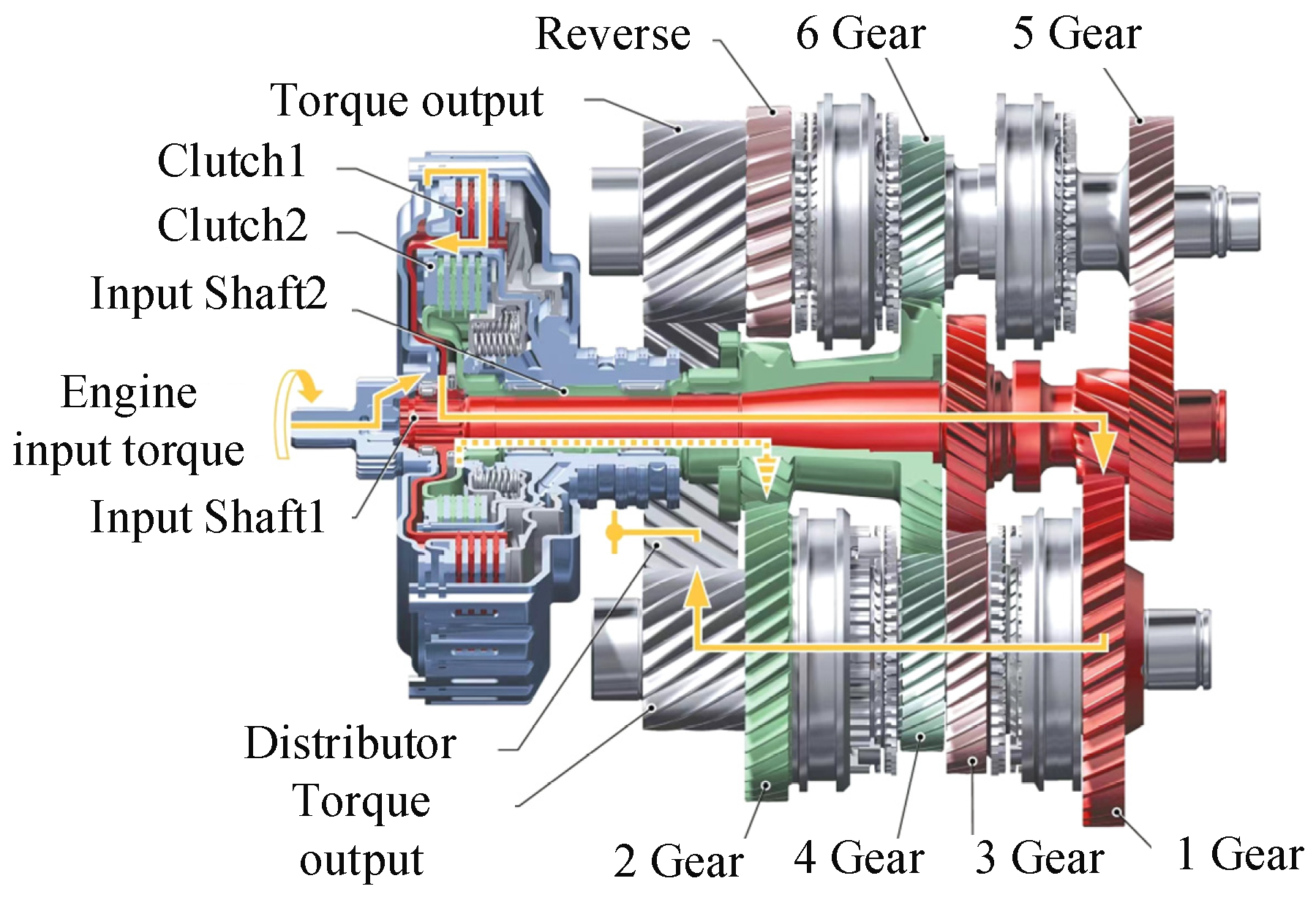
2. The Structure and Working Principle of DCT

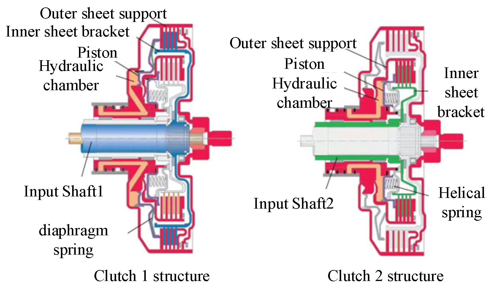
2.1. The Overall Structure of Wet Clutch

The structure of the DCT is shown in Figure 1. The transmission is mainly composed of three parts: clutch system, mechanical transmission mechanism, and hydraulic control system. The dual-clutch system incorporates two wet clutches, which are connected to the odd and even gears through a solid shaft and a hollow shaft, respectively. Gear shifting is achieved by controlling the engagement of different gear pairs and synchronizers.

2.2. Clutch System

The DCT clutch system consists of two clutches integrated together [23]. The entire system consists of a drive disc, a clutch inner plate bracket, a clutch outer plate bracket, a sealing ring, and a piston that compresses the friction plate, as shown in Figure 2. When the clutch is working normally, the engine torque is transmitted to the corresponding input shaft through the outer support. The gear distribution of DCT is that the first, third, and fifth gears are arranged on the input shaft 1, and the second, fourth, and sixth gears are arranged on the input shaft 2. When the C1 clutch engages, hydraulic oil enters the hydraulic chamber of clutch C1, compressing the piston. The piston pushes the diaphragm spring, causing the friction disc and the clutch plate of C1 to press together, engaging the clutch C1. Similarly, when C2 is engaged, hydraulic oil enters the hydraulic cavity of clutch C2, compressing the piston, which then pushes the spiral spring. This action presses the C2 friction plate and clutch plate against the fixed pressure plate.

2.3. The Working Principle of DCT

The working process of dual-clutch transmission is usually divided into two phases: torque phase and inertia phase. In the torque phase, one clutch begins to disengage and the other clutch begins to engage. Because the speed difference between the engine and the separation clutch is zero, the transmission ratio is maintained as the separation clutch transmission ratio. In order to separate the clutch, the oil pressure of the separation clutch is gradually reduced, the hydraulic oil chamber of the engagement clutch is gradually increased, and the power of the engine is gradually transferred from the separation clutch to the engagement clutch. When the separation clutch is completely separated, the torque phase ends and enters the inertial phase. In the inertial phase, the oil pressure of the engaging clutch continues to rise until the final value, and the engine torque decreases to reduce the speed difference with the engaging clutch, and then gradually increases. During the entire shift process, the gearbox always transfers power from the engine to the drive wheel without power interruption, which is the main advantage of DCT over other gearboxes.
As shown in Figure 3, taking the upshift from the first gear to the second gear as an example of clutch shift. When the DCT is in 1st gear, the clutch plate in clutch C1 engages with the friction disk, and clutch C2 is in a disengaged state, with no power transmission. When the vehicle speed is increased, the transmission ratio should be upshifted from 1st gear to 2nd gear. At this point, the synchronizer S3 engages in advance [18], and the hydraulic oil pressure inside the clutch C1 starts to decrease, the clutch plate and friction disk of C1 are gradually disengaged, and the transmission torque gradually decreases. Meanwhile, the hydraulic oil pressure of the clutch C2 gradually increases, and the torque transmitted by C2 gradually increases. The dynamic friction torque generated by the two clutches provides the acceleration power for the vehicle.
The torque phase ends when clutch C1 is completely disengaged. The engagement time of clutch C2 has a large effect on the slip work, so in order to minimize the generation of slip work, the engagement of clutch C2 should be completed as soon as possible. At the same time, it is necessary to control the engine speed and clutch C2 friction torque to reduce the relative speed difference so that the gearshift is smooth and fast. When C2 engagement is completed, the master–slave disk speed difference is zero, the inertia stage is over, and the power of the whole vehicle is transmitted by C2.

3. Shift Quality Evaluation Index

Shift quality is an important index for evaluating the smoothness and comfort of gear shifts. It refers to the vehicle’s ability to complete the shifting process smoothly and without impact, while ensuring the vehicle’s power performance and protecting the transmission system. Shift quality is primarily evaluated through two approaches: subjective and objective. Objective evaluation methods mainly include impact, sliding friction work, and shift time.
During the shift process of a DCT, the two clutches alternate between disengagement and engagement to ensure uninterrupted vehicle power while completing the shift. However, the coordination of the clutches significantly affects shift quality. In this paper, the shift performance of the dual-clutch transmission is evaluated using objective criteria, with the evaluation indices including impact severity and sliding friction work.

3.1. Impact Degree

The sense of frustration in the shifting process is mainly reflected in the influence of the vehicle longitudinal on the driver. The rate of change of the vehicle’s longitudinal acceleration is used to assess shift smoothness and comfort, with its derivative representing the shift jerk [24]. The shift time of the gearbox affects torque variation. If the shift time is too short, it can cause the torque to fluctuate greatly, resulting in a greater impact. Therefore, to minimize shifting impact, it is necessary to extend the shift duration as much as possible. The calculation formula is:
ε = d a d t = d 2 v d t 2 = R w i g i f × d 2 ω c d t 2 = R w i g i f J ce × d T c d t = R w J ce i g i f u
In the formula: a is the longitudinal acceleration of the vehicle; v is the speed of the car; RW is the radius of the driving wheel; ω c the angular velocity of the driving wheel; i g is the car central transmission ratio and i f is final transmission ratio. J c e is the moment of inertia of the output shaft of the power shift gearbox; T c is the output torque of clutch; u is the derivative of the output torque.

3.2. Slipping Work

Slipping work refers to the relative sliding of the engine and the clutch during the synchronization process, which causes the friction plate to continuously work on the sliding film and generate friction heat, which is the slipping work [25]. The accumulation of heat will lead to the increase of oil temperature and clutch friction plate temperature, which will affect the transmission efficiency of the transmission. Excessive heat will lead to large heat on the friction plate, aggravate the wear of the friction plate, reduce its service life, and affect the shift performance. Therefore, in order to reduce the heat, the engagement time needs to be as short as possible. The expression formula of sliding friction work is as follows
W c = t 0 t f ( i = 1 2 T c i | ω e ω c i | ) dt
In the formula: t 0 is the start time of the sliding state are respectively; t f is the end time of the sliding state are respectively; ω e  is the engine speed angular velocity;  ω c i is the clutch driven disc speed; T c i  is torque transmitted by wet clutch.

4. Design of Oil Pressure Control Trajectory During DCT Shifting

It is necessary to formulate a suitable oil pressure curve, so that the clutch transmission torque is smooth, the engagement efficiency is improved, and the impact is reduced. Ignoring the elasticity and vibration of the DCT system, the dynamic model of the DCT can be simplified into a discretized equivalent system. The shift dynamic model of the DCT system is shown in Figure 4.
Among them, J c e  is the inertia of the input shaft (together with the engine inertia), J c 1  and  J c 2  are the transmission inertia of the corresponding clutch input shaft, J o  is the equivalent rotational inertia of the drive shaft, J v  is the equivalent rotational inertia of the vehicle, i g 1  and i g 2  are the transmission ratios through the two shafts, i f 1 and  i f 2 are the deceleration transmission ratios of the two shafts.

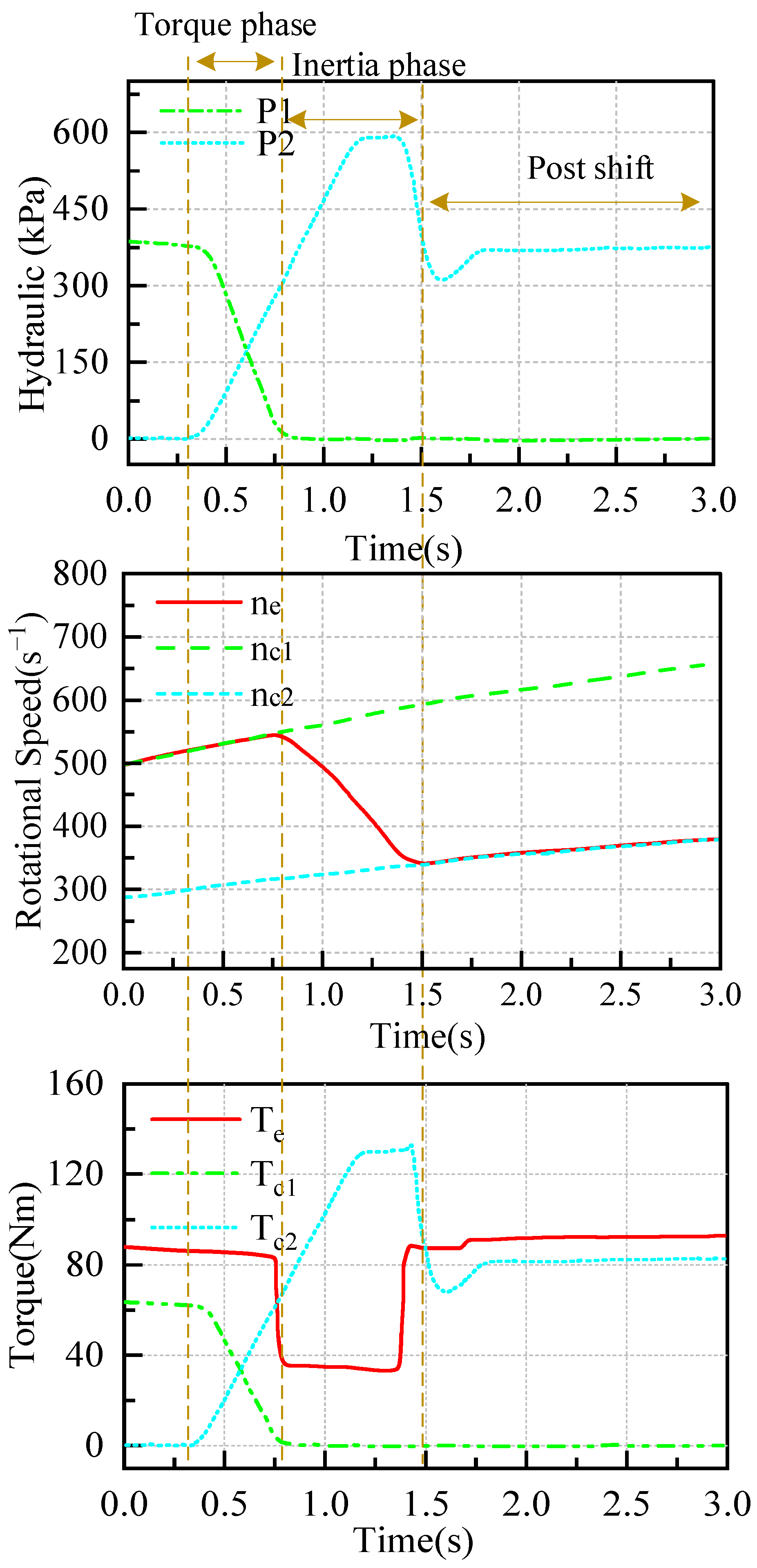
4.1. Torque Phase and Inertial Phase

As discussed in the first section of the DCT working principle diagram in Figure 3, clutches C1 and C2 transmit friction torque to the drive wheels during the torque stage. The friction torque of C1 decreases to zero, while the friction torque of C2 increases from zero to its final value. Based on the simplified model above, the dynamic equation of the transmission system is derived.
The torque balance equation from engine to clutch input is
J ce d ω e d t = T e T c 1 T c 2
In the formula, ω e  is the engine input speed, T e  is the engine input torque, T c 1  and T c 2  are the dynamic friction torque of C1 and C2, respectively.
Since both C1 and C2 transfer the friction torque to the intermediate shaft in the torque stage, the torque balance equation can be expressed as
J ˜ c 1 d ω c 1 d t = T c 1 + i g 2 i g 1 T c 2 T r i g 1 i f 1
J ˜ c 2 d ω c 2 d t = i g 1 i g 2 T c 1 + T c 2 T r i g 2 i f 2
In the formula, ω c 1  and ω c 2  are the input shaft speed of clutch C1 and C2, T c 1  and T c 2  are the input torque of clutch C1 and C2 respectively, T r  is the rolling torque of drive wheel, J ~ c 1  and J ~ c 2  are the total equivalent rotational inertia of C1, C2 and their drive shaft respectively.
The dynamic equation from the DCT output end to the vehicle wheel end is
δ m d u d t = T o r w F t
Among them, for the car rotating mass conversion coefficient is
δ = 1 + 1 m J w r w 2 + 1 m J f i g 2 i 0 2 η T r w 2
In the formula, J w  is the moment of inertia of the wheel, J f is the moment of inertia of the flywheel, i g  is the transmission ratio, i 0  is the main transmission ratio, T o  is the torque output by the drive shaft, r w  is the rolling radius of the drive wheel, m is the mass of the vehicle, F t   is the reaction force of the ground to the drive wheel.
During the shift process of DCT, the engagement clutch is in the separation state, and the separation clutch is in the combination state. The friction torque of the engagement clutch gradually increases, that is, the oil pressure gradually rises from the pre-charge oil pressure to gradually compress the friction plate until the clutch plate and the friction plate have no relative sliding. The oil pressure of the separation clutch is gradually reduced until the oil pressure is not enough to overcome the return pressure of the return spring. At this time, there is no contact between the clutch plates, and the output torque is zero. In the shift phase, the mathematical model of the relationship between the clutch output torque and the piston oil pressure can be simplified as:
T c = sgn ( ω ) μ R c Z A c P c
In order to simplify the calculation, let K be:
K = sgn ( ω ) μ R c Z A c
sgn ( ω ) = { 1 ω 0 1 ω < 0
sgn is used to represent the direction of the speed difference between the flywheel and the clutch.
R c = 2 3 r o 3 r i 3 r o 2 r i 2
Rc is the radius of the friction plate, r o   is the outer diameter of the friction plate, r i  is the inner diameter of the friction plate, Z is the number of friction surfaces, μ is the friction coefficient of the friction plate, Ac is the area of the clutch piston, and Pc is the difference between the current oil chamber pressure and the pre-filled oil pressure of the clutch.
The expression of the angular velocity relationship of different transmission shafts of the transmission system is
ω c 1 = i g 1 i g 2 ω c 2 = i g 1 i f 1 ω o = i g 1 i f 1 ω v
According to the above model, the equivalent rotational inertia relationship can be obtained as follows:
{ J ˜ c 1 = J c 1 + i g 2 2 i g 1 2 J c 2 + δ m r w 2 i g 1 2 i f 1 2 J ˜ c 2 = i g 1 2 i g 2 2 J c 1 + J c 2 + δ m r w 2 i g 2 2 i f 2 2
The gear shift includes torque phase and inertia phase, and the engine speed and torque need to be appropriately reduced. When the shift is to be completed, the engine speed is the same as the driven plate speed of the engagement clutch, which is set as ω e = ω c 2 . Which ω e   is the engine angular velocity, ω c 2   is the angular velocity of the engagement clutch. Here, it is assumed that the C1 clutch is a separation clutch and the C2 clutch is an engagement clutch.
According to the above dynamic model, the engine speed, C1 separation clutch slip, C2 engagement clutch slip, C1 separation clutch oil pressure, and C2 engagement clutch oil pressure is selected as state variables to establish the state equation. In this paper, the output torque of the clutch is controlled by adjusting the oil pressure in the hydraulic chamber. Therefore, the derivative of the oil pressure is selected as the control variable, allowing the change in output torque to be controlled and ensuring steady-state accuracy through its integral effect. The oil pressure of the separation clutch and the engagement clutch are set in a proportional relationship. The formula is P c 1 = k P c 2 , where k is the proportional coefficient.
For the control design, the state variable is selected as:
X = { x 1 x 2 x 3 x 4 x 5 } = { ω e ω e ω c 1 ω e ω c 2 P c 1 P c 2 }
X ˙ = { x ˙ 1 x ˙ 2 x ˙ 3 x ˙ 4 x ˙ 5 } = { d ω e d t d ω e d t d ω c 1 d t d ω e d t d ω c 2 d t d P c 1 d t d P c 2 d t }
U = { d P c 2 d t }
X is the state variable of the control equation, X ˙ is the derivative of the state variable of the governing equation. and U is the control variable of the control equation.
The mathematical model of the clutch in Equation (8) reveals the relationship between the clutch output torque and the clutch oil pressure. In order to simplify the calculation, let:
T c 1 = K 1 P c 1
T c 2 = K 2 P c 2
K1 and K2 are the proportional coefficients of clutch C1, C2 output torque and clutch oil pressure respectively.
From Equations (3)~(13), the dynamic model of the powertrain is:
{ x ˙ 1 = K 1 J ce P c 1 K 2 J ce P c 2 + T e J ce x ˙ 2 = ( K 1 J ce K 1 J ˜ c 1 ) P c 1 + ( K 2 J e d i g 2 i g 1 K 2 J ˜ c 1 ) P c 2 + T e J c e + T r J ˜ c 1 i g 1 i f 1 x ˙ 3 = ( K 1 J c e i g 1 i g 2 K 1 J ˜ c 2 ) P c 1 +   ( K 2 J c e K 2 J ˜ c 2 ) P c 2 + T e J c e + T r J ˜ c 2 i g 2 i f 2 x ˙ 4 = d P c 1 d t = k d P c 2 d t x ˙ 5 = d P c 2 d t
According to the above, the following control equations can be established:
X ˙ = A X + B U + Γ
The matrices A, B, and the interference matrix Γ are:
A = [ 0 0 0 K 1 J ce J ce 0 0 0   K 1 J ce K 1 J ˜ c 1 K 2 J ce i g 2 i g 1 K 2 J ˜ c 1 0 0 0 K 1 J ce i g 1 i g 2 K 1 J ˜ c 2   K 2 J ce K 2 J ˜ c 2   0 0 0 0 0 0 0 0 0 0 ]
B = [ 0     0     0     k     1 ] T
Γ = [ T e J ce T e J ce + T r J ˜ c 1 i g 1 i f 1 T e J ce + T r J ˜ c 2 i g 2 i f 2     0     0 ] T
The controllability matrix of the system is calculated under constraint u [ u min , u max ] , and the system is completely controllable, in which the interference term at the current time is considered to be a known constant.
Combining the evaluation index mentioned above with the state quantity Equation (14), we can obtain:
Sliding friction work is
W c = t 0 t f ( T c 1 | ω e ω c 1 | + T c 2 | ω e ω c 2 | ) d t = t 0 t f ( k K 1 x 4 | x 2 | + K 2 x 5 | x 3 | ) d t
Shift impact degree:
ε = d 2 v d t 2 = R w i g 2 i f 2 J ce d T c 2 d t = R w J ce i g 2 i f 2 u
When the clutch is shifting, it is necessary to make a compromise between the shift time and the shift smoothness. Increasing the shift time can make the clutch synchronization more stable and the shift impact smaller, but it will produce more sliding friction work and will be converted into friction heat and wear. Therefore, it is necessary to design a new objective function to optimize the weight ratio of the two. Thus, the system is controlled to obtain the optimal solution. After weighting the above indicators, the performance function is obtained as follows:
J = 1 2 t 0 t f Q 1 ( k K 1 x 4 | x 2 | + K 2 x 5 | x 3 | ) + Q 2 j 2 d t = 1 2 t 0 t f Q 1 ( k K 1 x 4 | x 2 | + K 2 x 5 | x 3 | ) d t + 1 2 t 0 t f Q 2 R w 2 J c e 2 i g 2 2 i f 2 2 u 2 d t
In the formula, t0 and tf are the starting and ending time of the engagement process; Q1 is the weighting coefficient of sliding friction work, and Q1 > 0; Q2 is the weighting coefficient of the jerk, Q2 > 0, and Q1 + Q2 = 1, ε is the shift jerk, and the square form is used to eliminate the influence of positive and negative values. Through the weighting coefficient Q1 and Q2, the proportion of the two indexes of sliding friction work and shift impact in the comprehensive evaluation index is determined. Thus, the optimization problem is described as finding the optimal control variable u(t) to obtain P C 1   and   P C 2 , so that the value of the performance functional is minimized under the above constraints.

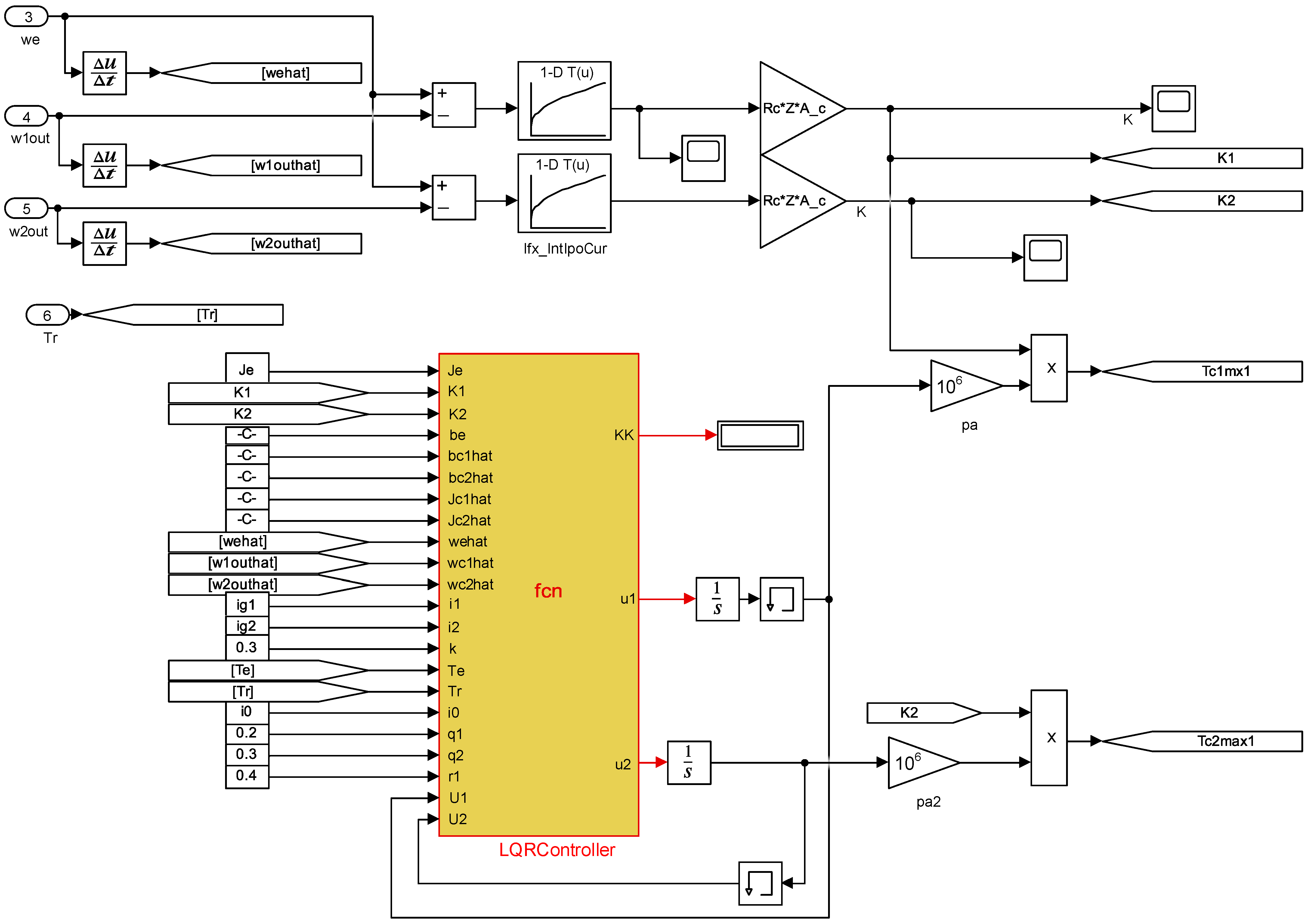
4.2. Optimization Problem Solving

In this paper, LQR controller is used to optimize the full state feedback control of clutch oil pressure by using terminal weighting matrix.
According to the performance functional obtained in (26), it is transformed into the standard form of the LQR function.
J = 1 2 t 0 t f ( x T Q x + R u 2 ) d t
The weighted matrix Q, R is
Q = [ 0 0 0 0 0 0 0 0 k Q 1 K 1 0 0 0 0 0 Q 1 K 2 0 0 0 0 0 0 0 0 0 0 ]
R = [ Q 2 R w 2 J ce 2 i g 2 2 i f 2 2 ]
Suppose that the control variable is assumed to be u ( t ) = u 1 ( t ) + p ( t ) .
According to the performance functional, the Hamiltonian equation can be directly obtained. After calculation, the following differential equations can be obtained
{ x ˙ = A x + B R 1 B T λ + Γ λ ˙ = Q x A T λ
Because of the interference term, let
λ = P x + h
Substituting Equation (31) into Equation (30), the following differential equation is obtained after conversion
P ˙ A T P P A + P B R 1 B T P Q = 0
P B R 1 B T h + P Γ h ˙ A T h = 0
The final control law can be obtained from Equations (32) and (33)
u = R 1 B λ = R 1 B ( P x + h )
The P matrix is obtained by solving the Riccati differential Equation (34). The compensation amount h introduced by to eliminate the interference term Γ is obtained by Formula (33).
The control structure and simulink model of LQR controller are shown in Figure 5 and Figure 6.
The main parameters of the above formula are shown in Table 1 and Table 2. MATLAB/Simulink (R2022b)is used to dynamically simulate the rising process of the proposed controller from gear 1 to gear 2 in the torque stage.

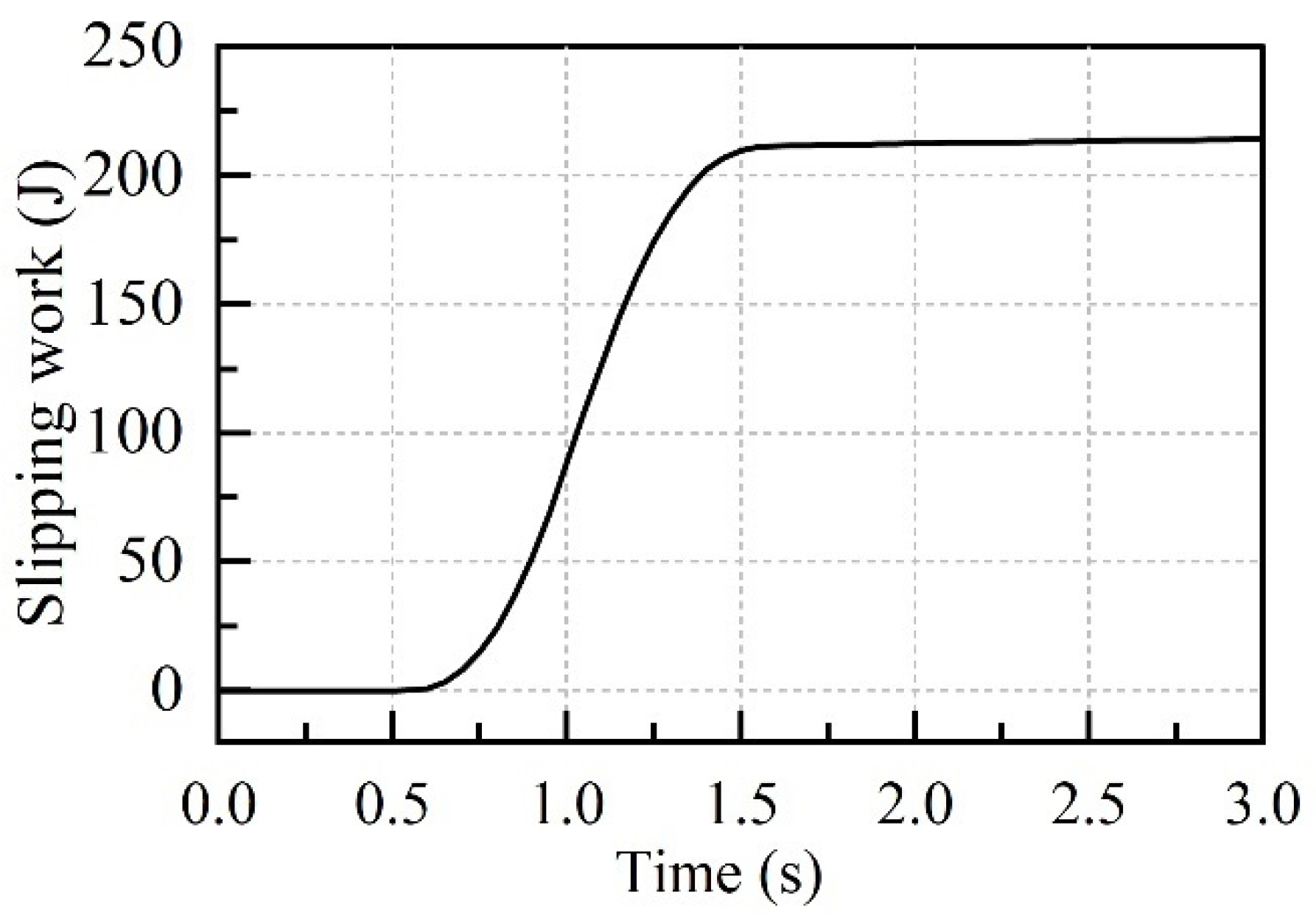
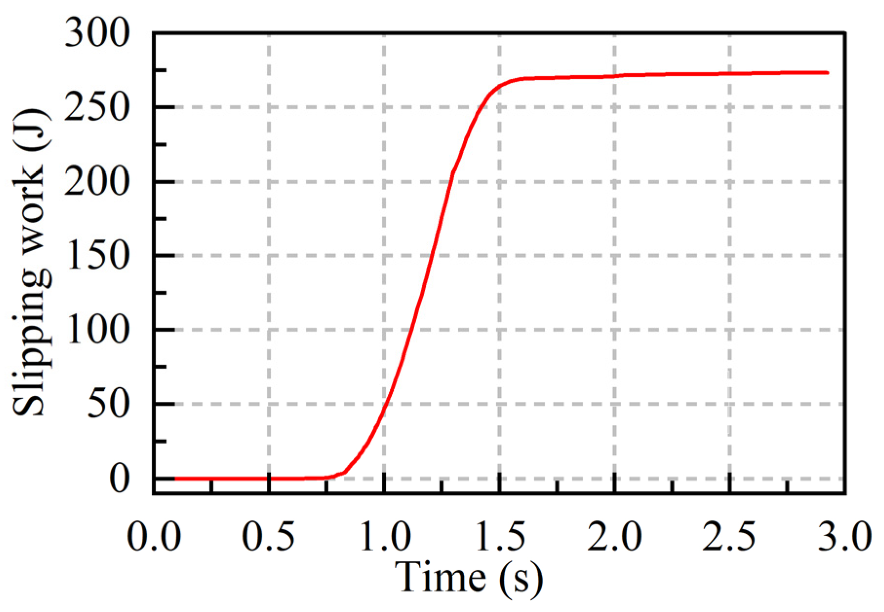
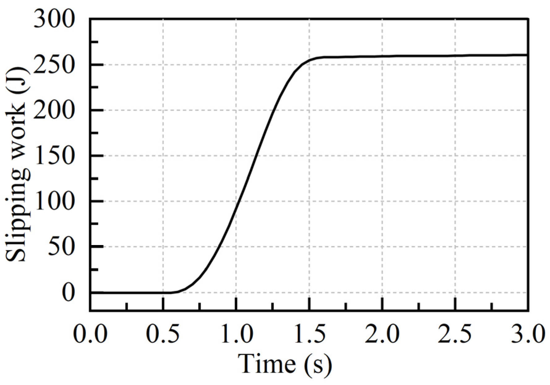
5. Simulation Results and Analysis

5.1. Comparison of Simulation Results Under Different Operating Conditions

In the process of shifting gears, the low gear switching is the initial stage of accelerating the vehicle from a standstill state to a higher speed, and the resulting shift impact and slippery work are larger, which can directly affect the driver’s driving experience. Therefore, this study verifies the anti-interference ability of the LQR algorithm and the reasonableness of the optimized control algorithm under the condition of shifting from one gear to two gears, and at the same time, sets 40% and 60% throttle opening conditions for the comparative analysis of the results.
Figure 7 and Figure 8 show the oil pressure, speed, and torque curves of the clutch during the torque phase and inertia phase at a throttle opening of 40% and 60% operating conditions, respectively. During the shift preparation time before the start of the torque phase, there is a small reduction in the input torque transmitted from the engine to the clutch CL1. During the inertia phase, the friction torques of CL1 and CL2 need to change smoothly in order to ensure smooth shifting. With the developed LQR controller, the CL2 friction torque is increased rapidly at the beginning to obtain a torque change that is opposite to the change in CL1 friction torque, and then gradually increased to the final value. Based on the optimized oil pressure change trajectory, at the end of the torque stage, P1 is regulated to 0 and CL1 frictional torque is zero. In the inertia stage, in order to achieve fast synchronization of CL2, the optimized engine input torque decreases with the speed difference between the flywheel and CL2. When the speed difference is zero, the input torque increases rapidly to the friction torque, thus ensuring smooth shifting and uninterrupted power transmission.
From the simulation results of Figure 7 and Figure 8, it can be seen that under different throttle openings, when the shift process transitions from the torque stage to the inertia stage, the speed difference between the engine input speed and the engagement clutch under both conditions can be rapidly reduced to reduce the sliding friction work. When the shift is about to end, the input torque can increase rapidly to ensure the stability of the shift process.
The shift jerk at 40% and 60% throttle openings are shown in Figure 9 and Figure 10, and the slipping work at different throttle openings are shown in Figure 11 and Figure 12. Comparison of the results shows that when the throttle opening is increased, the shock amplitude and slip work are slightly increased. This indicates that the increase in throttle opening worsens the shift quality. The simulation results show that the maximum absolute values of the shock are 5. 4 m/s3 and 8. 6 m/s3, which are lower than the German standard of 10 m/s3, and the total slipping work is 260J and 335J, respectively, which shows that when the throttle opening is increased, the LQR controller can control the slipping work and the shock generated by the clutch system in the ideal range by controlling the clutch torque and rotational speed.
The simulation of upshifting from 3rd to 4th gear at 40% throttle opening condition is shown in Figure 13. During the shift preparation time before the start of the torque phase, the torque of the C1 clutch fluctuates due to the shift action, but it does not affect the control of the optimization controller in the torque phase. Figure 14 and Figure 15 represent the shift impact degree and slip work for 3rd gear up to 4th gear, respectively. Compared with the low gear shift, in the high gear, the transmission ratio is smaller, the relative rotational speed between the engine and the engagement clutch is smaller, the slip friction work and shock degree generated are lower, and the shift quality of the whole vehicle is better.

5.2. Comparison of Simulation Results Under Different Control Strategies

The method proposed in this paper is compared with a control method using MATLAB particle swarm optimization (Jia et al., 2019) [26]. The Matlab particle swarm optimization algorithm cannot optimize the output torque of the engine and the output torque of the dual-clutch transmission. It is necessary to introduce the Fourier formula conversion. The calculation amount is large, the number of iterations is high, the calculation period is long, the response speed is low, and the controller requirements are high. The LQR control algorithm proposed in this paper is a linear control algorithm based on state space model. It can linearize the complex clutch system and feedback the system state in real time. It has efficient dynamic control and response speed, strong anti-interference ability and strong robustness.
During the simulation, the constraints at the beginning of the torque stage are set to have the engine speed equal to the speed of the disengaging clutch. At the end of the inertia stage, the engaging clutch assumes the torque output and the speed is equal to the engine speed. The change curves of slipping work of the reference control strategy and the optimized control strategy are shown in Figure 16 and Figure 17. The vehicle enters the upshift process at 0.5 s, at this time, the oil pressure of the disengaged clutch C1 starts to decrease, but the master–slave plate is in the combined state, and no slippage occurs, and there is no slippage work at this time. With the clutch C2 oil pressure gradually increased, began to transfer the engine torque, the master–slave plate is in the state of slippery friction, produce slippery friction work. In 1.6 s, the speed difference between the clutch and the engine speed is reduced to 0, no slip friction occurs, and the shift ends. Figure 16 and Figure 17 comparison can be seen, the control method proposed in this paper produces slipping work compared with the reference method reduces nearly 5.6%, and finally get the unit area slipping work is 0.12 J/mm3. Reference control strategy and optimization of the control strategy shifting impact change curve is shown in Figure 18 and Figure 19, in the 1.0 s before the torque stage, the engagement clutch is in the state of engagement, at 1.0 s, the engagement clutch C2 is responsible for the torque transmission, and the clutch C1 exits the combined state. At the time of disengagement of C1, a large degree of impact is generated. Comparison of the simulation results shows that the controller proposed by the reference control method has a lower response speed and produces a peak shock that lags behind the control method proposed in this paper, and produces a lower shock in the inertia phase, which reduces the vehicle’s jerks and has a better gearshift quality. The results show that the control method proposed in this paper can make the shock degree and slip work generated during the gearshift process are within the ideal range, which verifies the effectiveness of the control algorithm in this paper.

6. Conclusions

To optimize the shift performance and improve the shift quality, this paper proposes an oil pressure trajectory control method based on LQR. In the upshift process of DCT, the factors affecting the shift quality in the torque stage and the inertia stage are analyzed. The dynamic model of the transmission system is built and the spatial state equation is derived. The weighting function is constructed by combining with the sliding friction work and the impact degree. Finally, the LQR algorithm is used to solve the optimal oil pressure. The simulation results show that the proposed control strategy can effectively reduce the jerk and friction work of the shift vehicle and improve the shift quality. Compared with the control method using MATLAB particle swarm optimization, the control method developed in this paper can obtain smaller shift impact and less sliding friction work, and the shift smoothness is better. Under different throttle opening and shift conditions, the system has strong robustness and ensures the shift quality of the vehicle.

Author Contributions

Conceptualization, H.Z.; Methodology, X.X. and X.S.; Software, G.S. and X.Y.; Validation, G.S.; Writing—original draft, G.S.; Writing—review & editing, G.S. All authors have read and agreed to the published version of the manuscript.

Funding

This work was funded by the National Key Research and Development Project [2021YFB2501704].

Data Availability Statement

Data are contained within the article.

Conflicts of Interest

The authors declare no conflict of interest.

References

  1. Dai, X. Hydraulic Control System Analysis and Simulation Research of Wet Double Clutch Automatic Transmission. Ph.D. Thesis, Jilin University, Changchun, China, 2017. [Google Scholar]
  2. Zhang, Y. Master of Simulation Research and Analysis of Hydraulic Control System for Wet Dual-Clutch Automatic Transmission. Ph.D. Thesis, South China University of Technology, Guangzhou, China, 2020. [Google Scholar]
  3. Zhou, B. Research on Micro-Slip Control Method of Wet Dual-Clutch Transmission. Ph.D. Thesis, Shanghai Jiao Tong University, Shanghai, China, 2018. [Google Scholar]
  4. Liu, Y. Doctor of Integrated Matching Control for Dual-Clutch Transmission System of Passenger Car. Ph.D. Thesis, Chongqing University, Chongqing, China, 2010. [Google Scholar]
  5. Liu, Y. Shift Quality Simulation of Dual-Clutch Automatic Transmission. Ph.D. Thesis, Jiangsu University, Zhenjiang, China, 2017. [Google Scholar]
  6. Li, Y.T.; Zhao, Z.G.; Zhang, T. Simulation study of DCT transmission dual-clutch pressure optimal control method. China Mech. Eng. 2010, 12, 1496–1501. [Google Scholar]
  7. Fu, S.H.; Gu, J.H.; Li, Z.; Mao, E.R.; Du, Y.F.; Zhu, Z.X. Pressure control method for wet clutch of power shift transmission based on MFAPC. J. Agric. Mach. 2020, 12, 367–376. [Google Scholar]
  8. Wang, Q.; Meng, B.W.; Jia, W.J.; He, H.R. Research on optimal control of AMT vehicle starting clutch based on variational method. Shanxi Electron. Technol. 2019, 05, 75–78. [Google Scholar]
  9. Zhao, K.G.; Ning, W.L.; Ye, J. Optimal coordinated control strategy for AMT vehicle start based on minimum principle. J. Chongqing Univ. Technol. (Nat. Sci.) 2021, 2, 17–25. [Google Scholar]
  10. Wang, C.; Qin, D.T.; Wu, B.Z.; Fang, H.S.; Cheng, K. Simulation and analysis of wet clutch engagement characteristics. J. Chongqing Univ. 2020, 10, 38–51. [Google Scholar]
  11. MGoetz, M.C.; Crolla, D.A. Dynamics and control of gearshifts on twin-clutch transmissions. Proc. Inst. Mech. Eng. Part D J. Automob. Eng. 2005, 8, 951–963. [Google Scholar]
  12. Van Berkel, K.; Veldpaus, F.; Hofman, T.; Vroemen, B.; Steinbuch, M. Fast and Smooth Clutch Engagement Control for a Mechanical Hybrid Powertrain. IEEE Trans. Control. Syst. Technol.: A Publ. IEEE Control. Syst. Soc. 2014, 4, 1241–1254. [Google Scholar] [CrossRef]
  13. Walker, P.D.; Zhang, N.; Tamba, R. Control of gear shifts in dual-clutch transmission powertrains. Mech. Syst. Signal Process. 2010, 6, 1923–1936. [Google Scholar] [CrossRef]
  14. Liang, J.; Walker, P.D.; Ruan, J.; Yang, H.; Wu, J.; Zhang, N. Gearshift and brake distribution control for regenerative braking in electric vehicles with dual-clutch transmission. Mech. Mach. Theory 2019, 133, 1–22. [Google Scholar] [CrossRef]
  15. Kulkarni, M.; Shim, T.Y.; Zhang, Y. Shift dynamics and control of dual-clutch transmissions. Mech. Mach. Theory 2006, 2, 168–182. [Google Scholar] [CrossRef]
  16. Davis, G.; Donin, R.; Findlay, M.; Harman, P.; Ingram, M.; David, K. Optimisation of gear shift quality: By Means of Simulation. ATZ Worldw. 2004, 7–8, 23–26. [Google Scholar] [CrossRef]
  17. Jaecheol, C.; Yongseok, L.; Woojung, K.; Siyoul, J. Wet Single Clutch Engagement Behaviors in the Dual-Clutch Transmission System. Int. J. Automot. Technol. 2017, 19, 463–472. [Google Scholar]
  18. Byeon, S.J.; Kim, S.J.; Park, J.K.; Park, Y.J.; Lee, J.W. Parameter Study for Establishing a Synchronizer Control Strategy in Tractor Dual-Clutch Transmission. Agriculture 2024, 14, 218. [Google Scholar] [CrossRef]
  19. Hao, H.; Ma, H. Optimizing Gearshift Control of Wet Dual Clutch Transmission. Mech. Sci. Technol. Aerosp. Eng. 2022, 41, 936–947. [Google Scholar]
  20. Xiang, Y.; Li, R.; Brach, C.; Liu, X.; Geimer, M. A Novel Algorithm for Hydrostatic-Mechanical Mobile Machines with a Dual-Clutch Transmission. Energies 2022, 15, 2095. [Google Scholar] [CrossRef]
  21. Chen, Y.T.; Cheng, Z.; Qian, Y. Research on Wet Clutch Switching Quality in the Shifting Stage of an Agricultural Tractor Transmission System. Agriculture 2022, 12, 1174. [Google Scholar] [CrossRef]
  22. Li, Y.; Bao, D.; Tang, W. LQR control of a flexible ball screw feed system with a generalized extended state observer. J. Jiangsu Univ. (Nat. Sci. Ed.) 2019, 40, 446–450+457. [Google Scholar]
  23. Zhang, Z.; Wu, X.; Yang, C.; Zou, B. Research on precise control methods for clutch torque in the shifting process of wet DCT. J. Chongqing Univ. Technol. (Nat. Sci. Ed.) 2023, 37, 8–18. [Google Scholar]
  24. Zhao, D.; Cui, G.; Li, D. Shift quality of the transmission system in engineering vehicles. J. Jiangsu Univ. (Nat. Sci. Ed.) 2008, 5, 386–389. [Google Scholar]
  25. Hu, F.; Sun, D.; Qin, D.; Chen, R.; Luo, Y. Modeling and Simulation of the Joint Starting Mode of DCT Dual Clutch. J. Jiangsu Univ. (Nat. Sci. Ed.) 2010, 31, 19–25. [Google Scholar]
  26. Jia, Y.T.; Tian, J.Y.; Gu, Y.H.; Xia, C.G. Minimization of shift friction work and jerk of DCT for electric vehicles. J. Guangxi Univ. (Nat. Sci. Ed.) 2019, 5, 1355–1362. [Google Scholar]
Figure 1. DCT gear transmission mechanism.
Machines 12 00903 g001
Figure 2. Clutch structure.
Machines 12 00903 g002
Figure 3. Schematic of the DCT Working Principle (Red arrow: torque transmitted from the engine to the gearbox; Yellow arrow: route of the clutch C1 torque transfer in first gear; Green arrow: upshift to second gear, clutch C2 torque transmission route; Blue arrow: transmission torque transfer to the wheels.).
Machines 12 00903 g003
Figure 4. DCT transmission model.
Machines 12 00903 g004
Figure 5. Controller control process.
Machines 12 00903 g005
Figure 6. LQR controller simulink model.
Machines 12 00903 g006
Figure 7. Shift simulation at 40% opening.
Machines 12 00903 g007
Figure 8. Shift simulation at 60% opening.
Machines 12 00903 g008
Figure 9. 40% opening impact degree.
Machines 12 00903 g009
Figure 10. 60% opening impact degree.
Machines 12 00903 g010
Figure 11. 40% opening sliding friction work.
Machines 12 00903 g011
Figure 12. 60% opening sliding friction work.
Machines 12 00903 g012
Figure 13. Torque change from 3rd to 4th gear.
Machines 12 00903 g013
Figure 14. Shift jerk of 3rd gear to 4th gear.
Machines 12 00903 g014
Figure 15. Slipping work for 3rd gear to 4th gear.
Machines 12 00903 g015
Figure 16. Reference controller.
Machines 12 00903 g016
Figure 17. Proposed controller.
Machines 12 00903 g017
Figure 18. Reference controller.
Machines 12 00903 g018
Figure 19. Proposed controller.
Machines 12 00903 g019
Table 1. Main parameters of clutch.
Clutch NumberInside
Diameter
(mm)
Outside
Diameter
(mm)
Friction
Surface
C11912102
C21431692
Table 2. Transmission system and vehicle model simulation parameters.
CharacterInterpretationParameter ValueUnit
JceThe input equivalent moment of inertia 0.20(kg·m2)
Jc1Input shaft 1 equivalent moment of inertia0.043(kg·m2)
Jc2Input shaft 2 equivalent moment of inertia0.045(kg·m2)
JoEquivalent rotational inertia of drive shaft0.04(kg·m2)
JvVehicle equivalent rotational inertia149.94(kg·m2)
ig1A gear speed ratio4.83 ( / )
ig2Two gear speed ratio3.25 ( / )
mComplete vehicle quality1600(kg)
fCoefficient of rolling resistance0.015 (/)
CDCoefficient of air resistance0.0293(/)
r w   Wheel rolling radius0.30 (m)
ηTMechanical transmission efficiency92(%)
AVehicle windward area2.095(m2)
Disclaimer/Publisher’s Note: The statements, opinions and data contained in all publications are solely those of the individual author(s) and contributor(s) and not of MDPI and/or the editor(s). MDPI and/or the editor(s) disclaim responsibility for any injury to people or property resulting from any ideas, methods, instructions or products referred to in the content.

