Article

Multi-Objective Optimization Design of Dual-Spindle Component Based on Coupled Thermal–Mechanical–Vibration Collaborative Analysis

1
Key Laboratory of Air-Driven Equipment Technology of Zhejiang Province, Quzhou University, Quzhou 324000, China
2
College of Mechanical Engineering, Zhejiang University of Technology, Hangzhou 310023, China
3
Engine Factory of Sinotruk Jinan Power Co., Jinan Ltd., Jinan 250200, China
*
Author to whom correspondence should be addressed.
Machines 2024, 12(12), 885; https://doi.org/10.3390/machines12120885
Submission received: 4 October 2024 / Revised: 1 December 2024 / Accepted: 3 December 2024 / Published: 5 December 2024

Abstract

To comprehensively improve the thermal, static and dynamic characteristics and achieve lightweighting for CNC machine tools, this paper proposes a multi-objective joint optimization method based on coupled thermal–mechanical–vibration collaborative analysis. The dual-spindle component of a CNC machine tool is taken as the parameterized model. According to the theories of thermal characteristics, statics, and dynamics, the solution of thermal-mechanical coupling deformation and the solution of vibration characteristics under prestress are repeatedly conducted, that are working collaboratively with each process of parameters sensitivity computing, selection of design variables, central composite design, and multi-objective joint optimization. The response surfaces of the objective functions are established. The optimal parameter combination for improving CNC machine tool performance is effectively obtained. And the multiple objectives of improving the thermal, static and dynamic characteristics, as well as lightweighting, are achieved. The results show that the mass of the optimized component is reduced by 10.1%; the first-order natural frequency is increased by 3.9%; the coupling deformation of the end face of the left spindle seat is reduced by 5.3%; and the coupling deformation of the end face of the right left spindle seat is reduced by 9.0%, while the temperature of the component hardly increases. This indicates that this method can comprehensively improve the performance of CNC machine tool components and provide a reference for the multi-objective joint optimization design of CNC machine tools.

1. Introduction

With the continuous development of modern industry, improving machining efficiency and accuracy has become an important goal in the equipment manufacturing industry [1]. As the industrial mother machine, the CNC machine tools are the top priority of the development in the equipment manufacturing industry. Dual-spindle CNC machine tools have a large advantage in machining efficiency. However, compared to single-spindle CNC machine tools, the dual-spindle configuration and its feed system increase the impact of the thermal, static and dynamic characteristics of the structure on product quality. Multiple sets of servo motors and transmission mechanisms serve as heat sources for one another, increasing the complexity of heat transfer. The coaxial feed of two spindles not only increases the mass of the component, but also weakens the static and dynamic characteristics. This can result in a decrease in machining accuracy, despite an increase in machining efficiency. Therefore, for dual-spindle CNC machine tools, it becomes an effective method to improve component performance by simultaneously realizing multi-objective joint optimization design from the aspects of heat transfer, force bearing, and vibration.
There are a lot of studies on the optimization design for the component structure of the CNC machine tool. Lajili et al. [2] modeled the simple shape of a hard-metal-cutting CNC machine tool and parametrically optimized the structure to minimize the mass under the constraint of minimum stiffness. Lorcan et al. [3] solved the tool wear and breakage problem of micro-end mill tools for CNC machine tools. They optimized the maximum deformation and equivalent stresses through static stress and deflection finite element analysis to improve stiffness and hardness of the tool. Yuksel et al. [4] combined the contact problem framework with a stabilizing contact stiffness function and used the calculated local deformation at the point of contact to determine the contact stiffness. They optimized the mass, static stiffness and natural frequency of the CNC machine tool using the contact constraint topology optimization technique. Huang et al. [5] conducted static and dynamic characteristic experiments on the CNC machine tool to find out the weak parts of the whole structure. And they optimized the mass, static deformation and low-order natural frequency of the weak structural parts by means of external contour topology optimization, internal fascia structure redesign and key dimension optimization. Liu et al. [6] developed an optimal design system for gantry CNC machine tools. The system can realize the lightweight design function based on a secondary optimal design method that integrates zero-order optimization, parameter rounding and structural re-optimization. Ding et al. [7] analyzed the dynamic performance of the rotating components of an ultra-precision fly cutting CNC machine tool and proposed three optimization schemes for the rotating components. Based on the results of the dynamic analysis, the best optimization scheme was found to largely reduce the tip displacement and optimize the dynamic performance of the CNC machine tool. Yang et al. [8] proposed a multi-objective joint optimization scheme using a non-parametric response surface methodology with the bed of the CNC machine tool as the research object. The maximum shape of the machine tool bed, the first-order natural frequency, and mass were optimized. Chang et al. [9] chose a five-degrees-of-freedom parallel machine tool with the TRR-XY hybrid mechanism as the research object and used inverse solution analysis to create the workspace of the machine tool. They improved the workspace while reducing mass through design parameter optimization.
The above studies mainly focus on the optimization of the mass, static stiffness and vibration resistance of the CNC machine tools. The optimization combined with thermal characteristics for CNC machine tools has received less attention. In actual working conditions, the components of CNC machine tools undergo thermal deformation and stress due to thermal expansion, which can affect static and dynamic characteristics [10]. Thermal deformation is the main source of error for CNC machine tools, accounting for 40% to 70% of the total error. Thermal deformation directly leads to a decrease in machining accuracy [11]. On the other hand, the internal stress generated by the loading of heat and force affects the natural frequency of the component. This paper proposes a multi-objective joint optimization design method of dual-spindle components for CNC machine tools based on coupled thermal–mechanical–vibration collaborative analysis. And the lightweight, thermal–mechanical coupling deformation and first-order natural frequency of the dual-spindle component are comprehensively promoted.

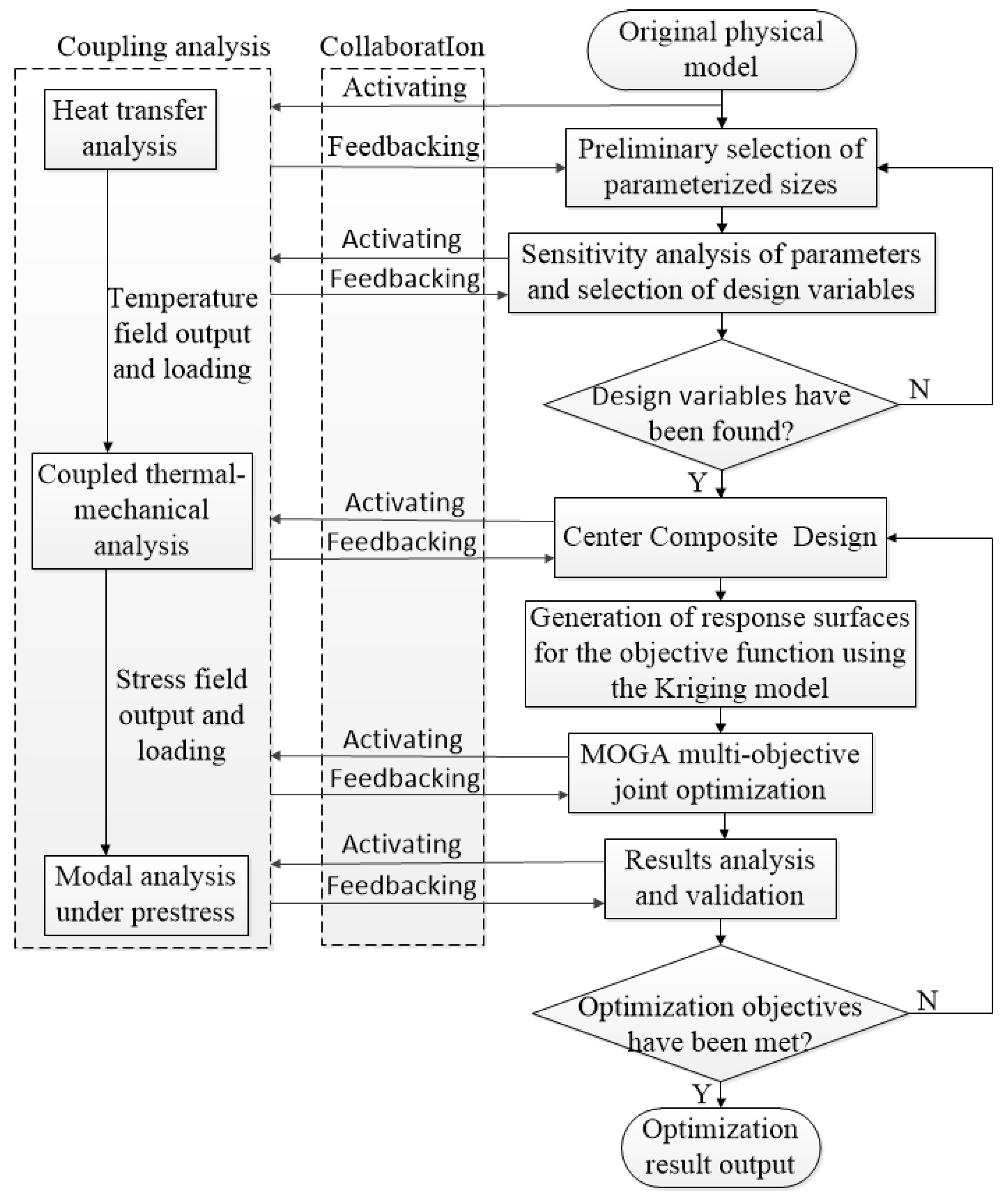
2. Optimization Method Based on Coupling Collaborative Analysis

The deformation of CNC machine tools due to heat is an important factor affecting the machining accuracy, while structural deformation has less effect on the change in temperature of CNC machine tools. Therefore, thermal analysis can be conducted first on the dual-spindle component of the CNC machine tools. And the analysis results can be transferred to the static analysis using a unidirectional coupling method. Then, the thermal–mechanical coupling deformation of component can be obtained [12]. The heat transfer process within the component system satisfies the following formula [13]:
ρ C P T t = k T + S
where ρ is the density of the part, C p is the specific heat, T is the temperature, t is the time, k is the thermal conductivity, and S is the heat source.
The CNC machine tool component is affected by heating from motors, bearings, and cutting heat during machining. Temperature rise leads to volume expansion whose degree is characterized by the thermal expansion coefficient. Thermal expansion causes the structure to deform in all directions. The thermal deformation and thermal expansion coefficient satisfy the following formula [14]:
Δ L T = α T L Δ T
where Δ L T is the thermal deformation; α T is the thermal expansion coefficient; L is the original size; Δ T is the temperature rise.
In addition to thermal deformation, the CNC machine tool component can also deform when subjected to external forces. The deformation is calculated by the following equation:
Δ L = F L E A
where Δ L is the deformation under the external forces; F is the magnitude of the combined force; E is the elastic modulus; A is the area under force.
Under the condition of thermal–mechanical coupling, the total strain of the component structure mainly consists of normal and shear strain generated by temperature and force. According to the Generalized Hooke’s law, the normal strain satisfies the following physical equation [15]:
ε x = 1 E σ x μ ( σ y + σ z ) + α T Δ T ε y = 1 E σ y μ ( σ x + σ z ) + α T Δ T ε z = 1 E σ z μ ( σ y + σ x ) + α T Δ T
where ε x , ε y , ε z are normal strains along x, y, z directions; σ x , σ y , σ z are stresses along x, y, z directions; μ is the Poisson ratio.
The shear strain is generated by the shear stress. The shear strain can be calculated by the following equation [16]:
γ x y = τ x y / G γ y z = τ y z / G γ x z = τ x z / G
where γ is the shear strain; τ is the shear stress; G is the shear modulus; xy, yz, xz are the directions of the strain or stress.
Dynamic characteristics have a significant impact on the machining accuracy of a CNC machine tool [17]. For dual-spindle CNC machine tools, the natural frequency obtained through modal analysis is the main measurement indicator of dynamic characteristics, which is only related to the material and shape and is constrained by the boundary load. The theoretical equations for modal analysis are as follows [18]:
K ω 2 M x = 0
where K is the stiffness matrix; M is the mass matrix; ω is the natural frequency; x is the displacement vector.
Under static load constraints, the volume of the component changes and internal stresses are generated, which results in a change in structural stiffness. Modal analysis with prestress couples the results of the thermo-mechanical analysis directly and is able to solve the vibration mode of the component under the influence of stress [19]. According to the fourth strength theory, the prestress applied to the component in modal analysis can be expressed by the Mises equivalent stress, which is calculated as follows [20]:
σ e = 1 2 ( σ x σ y ) 2 + ( σ y σ z ) 2 + ( σ z σ x ) 2
where σ e is the Mises equivalent stress.
During the operation of the CNC machine tool, low-order vibration is the main form of the structure vibration, which should be solved by modal analysis [21].
Based on the above theories, the collaborative analysis mechanism of coupled thermal-mechanical–vibration for component structures can be established, which will be repeatedly calling in subsequent optimization steps.
The dimensional parameters can be selected initially from the results of the first coupling analysis. The design variables are screened through parameter sensitivity analysis. For parameter data with non-linear relationships, the correlation matrix can be derived using Spearman correlation analysis. This method does not require a priori knowledge to obtain sensitivities between the probability distributions of the data samples [22]. The Spearman correlation coefficient ranges between ±1. The closer its absolute value is to 1, the higher the correlation is. Spearman correlation coefficient ρ is calculated as follows [23]:
ρ = i = 1 p R i R ¯ S i S ¯ i = 1 p ( R i R ¯ ) 2 i = 1 p ( S i S ¯ ) 2
where R i , S i is the order of sampling points in all the samples; R ¯ , S ¯ is the average value of R i , S i ; p is the total number of observed samples.
In order to obtain accurate experimental data, this paper chooses the Center Composite Design (CCD) method for experimental design, which can continuously add the center point and the axis point to form the bending response variable. This method can minimize the number of experiments as much as possible and has high accuracy. The second-order polynomial equation for predicting the experimental values of the response is as follows [24]:
Y = β 0 + i = 1 k β i x i + i k β i i x i 2 + 1 i j k β i j x i x j + ε
where Y is the response variable; β 0 , β i , β i i , β i j are the constant, linear, quadratic and interaction coefficients; ε is the residual value; k is the number of experimental variables.
The response surface model is a mathematical function model in mathematics and statistics. This model can solve optimization objectives influenced by multiple design variables [25]. To ensure that the analysis results of each experiment are relatively accurate, it is necessary to select an appropriate model to improve the fitting accuracy of the response surface. In this paper, the Kriging method is used to generate the multi-objective response surface. It is a regression algorithm model for spatial prediction of stochastic processes based on the covariance function. The Kriging method can obtain a high fitting accuracy for different experimental sampling methods. Its expression is as follows [26]:
y x = i = 1 k β i f i x + z x
where y x is the predicted response value of the point to be measured; f i x is the regression function of the sample point i; β i is the regression coefficient of f i x ; z x is the static random function with a mean of 0 and its covariance matrix is as follows [27]:
C o v z x i , z x j = σ 2 R x i , x j
where σ 2 is the variance; R ( x i , x j ) is the correlation function between any two sample points, i.e., x i and x j , in the whole sample space.
The optimization objectives in this paper are determined as follows: the mass of the component needs to be as small as possible to achieve the requirements of being lightweight; in order to improve the vibration performance, it is necessary to increase the natural frequency; the thermal–mechanical coupling deformation of the end faces on the left and right spindle seats is needed to be reduced, which can improve the stiffness of the component under the joint action of heat and force.
In this paper, the Multi-Objective Genetic Adventure (MOGA) is used to solve the Pareto solution set and obtain the best optimization result. It is an effective non-dominated genetic algorithm and a hybrid variant of an algorithm that supports different types of input parameters [28]. The range setting of design variables needs to consider their changes to avoid interference between the parts and meet operational requirements. The temperature boundary condition of the component cannot be higher than the maximum operating temperature of the CNC machine tool. To minimize the mass of the component and the thermal–mechanical coupling deformation of the end faces on the left and right spindle seats, and maximize the first-order natural frequency, the optimization function is used, which can be expressed as follows:
X = x 1 , x 2 , , x n 1 , x n T min m X min δ m a x l e f t X min δ m a x r i g h t X max f 1 X s . t T T m a x x m i n x i x m a x
where X is the matrix of the design variables; m X is the mass of the component; δ m a x l e f t X and δ m a x r i g h t X are the thermal–mechanical coupling deformation of the end faces on the left and right spindle seats; f 1 X is the first-order natural frequency of the component; T m a x is the maximum operating temperature of the CNC machine tool; x m i n and x m a x are the lower and the upper limit value of the design variables, respectively.
The flow chart of multi-objective joint optimization design based on coupled thermal–mechanical–vibration collaborative analysis is shown in Figure 1.

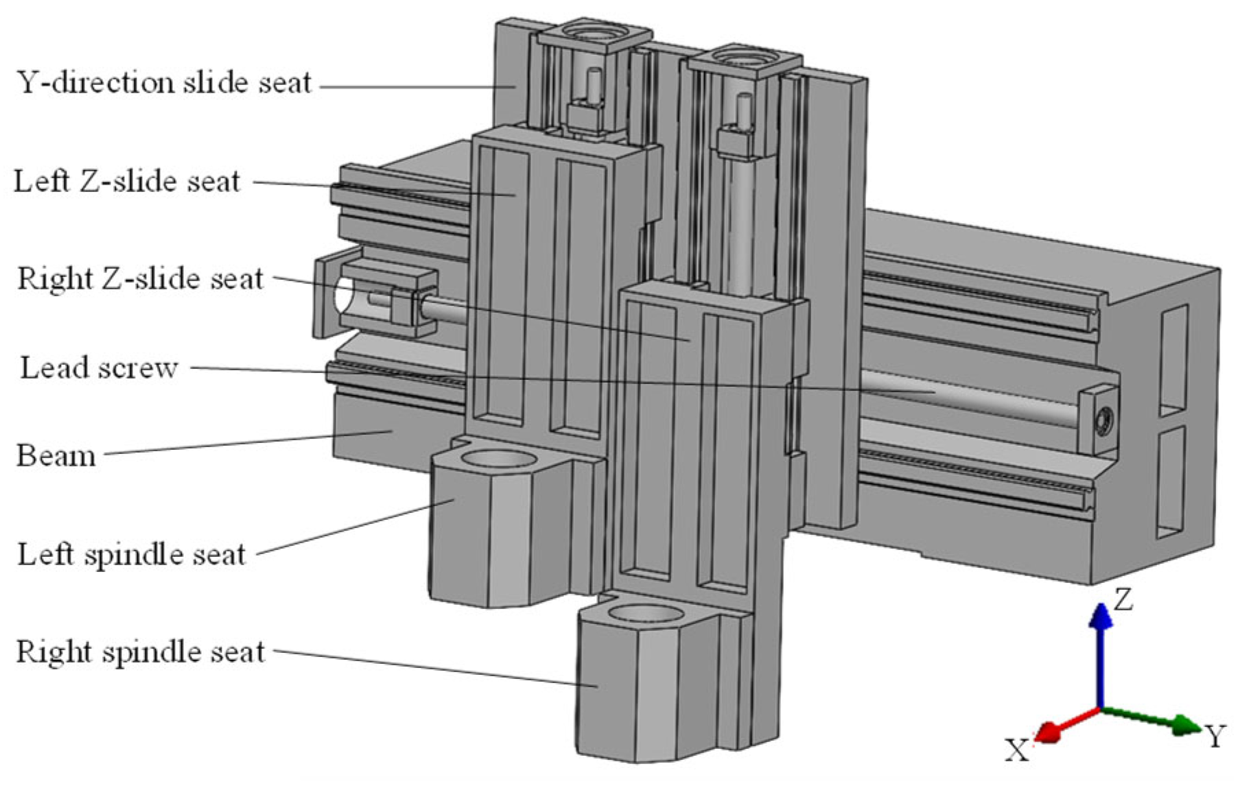
3. Load Analysis for Spindle Component of CNC Machine Tool

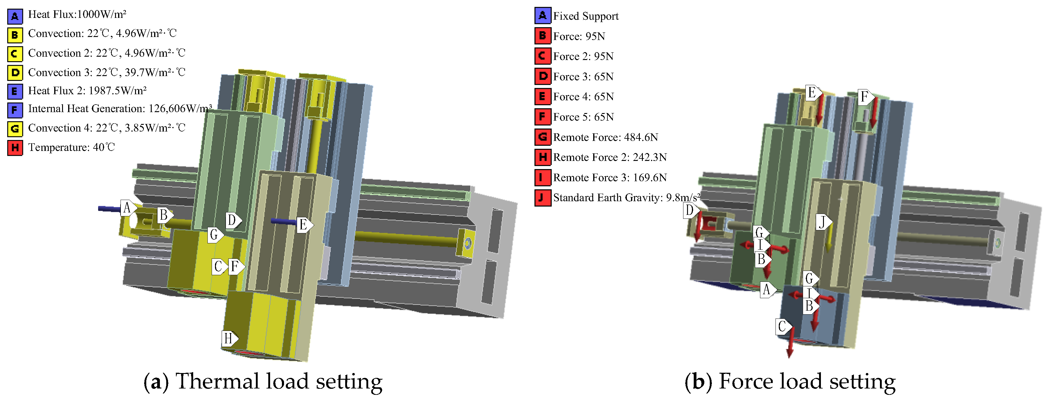
3.1. Thermal Load Calculation

When the feed system of the dual-spindle component is working, the screw nut pair and bearings generate heat. The heat generated by the bearings at both ends of the lead screw Q is calculated by the following equation [29]:
Q = 0.1047 M n
where M is the total frictional moment; n is the lead screw speed.
According to Palmgren’s empirical equation, the total frictional moment M is as follows:
M = M 0 + M 1
where M 0 is the moment related to lubrication and the type of bearing; M 1 is the moment related to the load; M 0 can be calculated by the following equation [30]:
M 0 = 10 7 f 0 v n 2 3 D m 3 v n 2000 160 × 10 7 f 0 D m 3 v n < 2000
where D m is the bearing pitch diameter; f 0 is the coefficient related to the type of bearing and lubrication method; v is the kinematic viscosity of the lubricant.
The lead screw is fixedly connected to the slide seat of the component. During the feed movement of the lead screw, the lead screw nut pair generates frictional heat on the contact surfaces. The heat flow density on the contact surfaces is calculated by the following equation [31]:
q = Δ t λ L t
where Δ t is the contact temperature difference; λ is the thermal conductivity; L t is the heat transfer length.
According to the theory of electromagnetism, the heat generation of the lead screw driven motor is calculated by the following equation [32]:
q m = M T n 9550 1 η
where q m is the heat production rate of the motor; M T is the output moment.; η is the mechanical efficiency.
There are two carving and milling motorized spindles installed on the spindle seats of the dual-spindle component. The spindles have water-cooling properties and their surface temperature during operation is generally around 40 °C. This temperature is loaded as the first boundary condition at the installation position of the electric spindle.
Due to the low working temperature of the components, the influence of thermal radiation is neglected in this paper. The main heat dissipation of the components is convective heat transfer with the air, including natural convective heat transfer and forced convective heat transfer. The convective heat transfer coefficient h is calculated by the following equation:
h = N u λ l
where N u is the Nusselt number; l is the characteristic size.
Forced convective heat transfer occurs on the surfaces of the screws and the inner rings of the bearings. The Nusselt number is calculated as follows [33]:
N u = 0 . 133 R e 2 3 P r 1 3 R e = ω d ν
where R e is the Reynolds number; P r is the Prandtl number; ω is the angular velocity of rotation; d is the nominal diameter.
Natural convective heat transfer occurs between the remaining surfaces of the component and the air. The Nusselt number is calculated as follows [34]:
N u = C P r G r n G r = g α Δ t l 3 ν 2 P r = μ C P λ
where C , n is the experimental constant; G r is the Grashof number; g is the gravitational acceleration; α is the volume expansion coefficient of the air; μ is the dynamic viscosity; C P is the specific heat at a constant pressure.

3.2. Force Load Calculation

The dual-spindle component is mainly subjected to gravity and cutting forces. According to metal cutting theory, the cutting force can be calculated by the following empirical equation [35]:
F = C F a P X F f Y F v c n F K F
where C F is the influence coefficient of the workpiece on the cutting force; a p is the cutting depth; f is the feed rate; v c is the cutting speed; X F , Y F , n F are the cutting indices; K F is the correction factor.
Cutting force is divided into tangential force F C , radial force F P and axial force F f . The relationship between each force is as follows [36]:
F P = 0.35 ~ 0.40 F C F f = 0.80 ~ 0.90 F C

4. Coupled Thermal–Mechanical–Vibration Analysis and Design Variable Selection

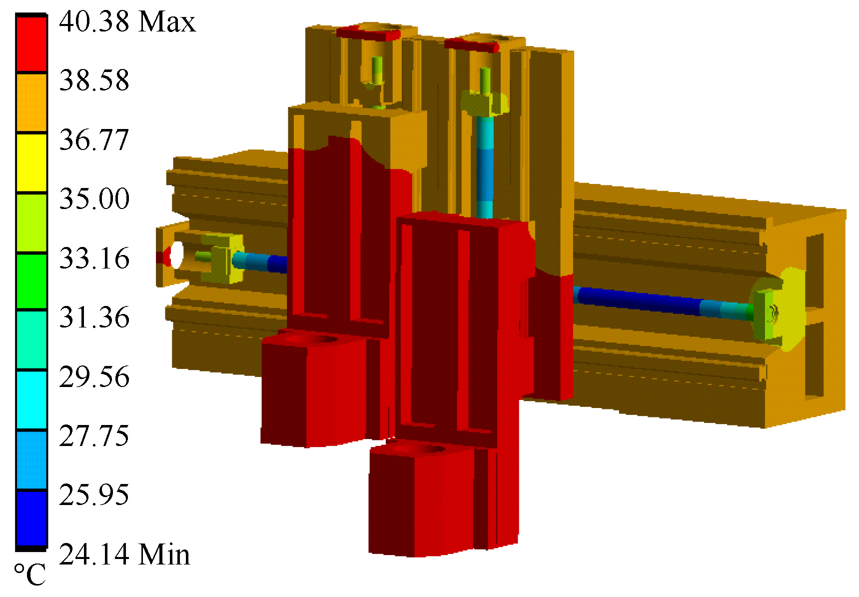
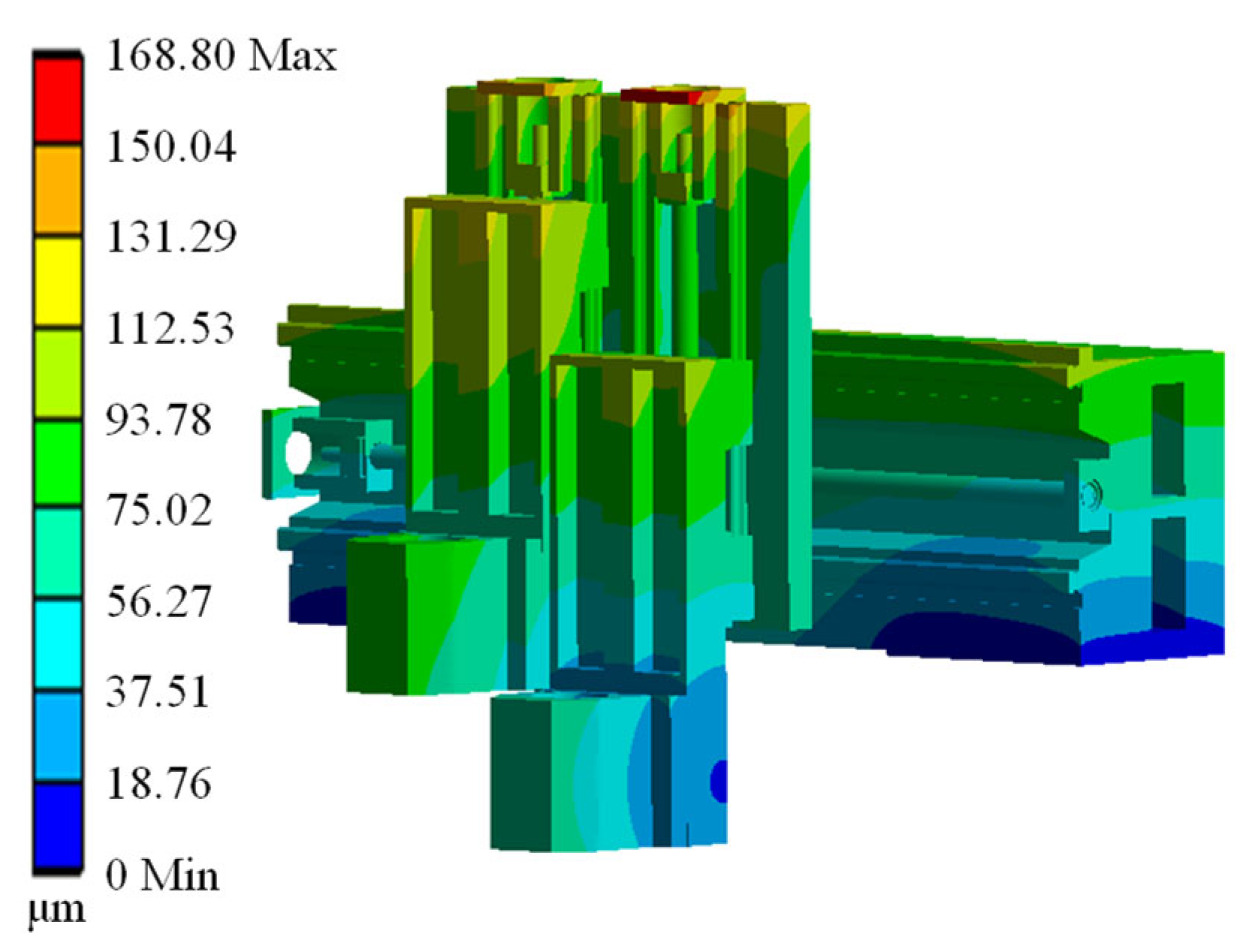
4.1. Coupling Analysis

The dual-spindle component of the G650 CNC machine tool is taken as the analysis object. Its model is established as shown in Figure 2. Based on the fact that more working conditions of dual spindles are located at different Z-value positions, using the upper motion limit of two Z-slide seats as the zero point in the mechanical coordinate system, here the Z-coordinate values of the left Z-slide seat and the right Z-slide seat are set to −100 mm and −250 mm, respectively.
The material of bearings in the dual-spindle component is Cronidur 30. The screws and sliding rail are modulated 45 steel, and the rest of the components are HT300. The material properties are shown in Table 1.
In this paper, the finite element method is used to solve the thermal, static and dynamic characteristics of the dual-spindle component. Before solving, in order to reduce the difficulty of mesh division and improve the computational efficiency, the chamfer and other structures that have less influence on the calculation results are simplified. The through holes and threaded holes used for connecting and fixing are removed. The connections between parts are bounded. The multi-zone method is used to mesh the dual-spindle component. For local complex parts, the tetrahedral patch conformal method is used to mesh. The global and local mesh sizes are adjusted so that the meshes on the different parts are adapted to the gradient changes in the solution values. The total numbers of meshes and nodes are 353,666 and 719,572, respectively. According to the above theories and operating conditions, boundary conditions are loaded onto the dual-spindle component as shown in Figure 3. After thermal–mechanical coupling calculation, the temperature distribution and deformation of the component are carried out, as shown in Figure 4 and Figure 5.
As seen in Figure 4, the highest temperature of 40.38 °C appears in spindle seats because of the heat sources such as the motorized spindle, feed motor, and bearings. In Figure 5, we can see that the deformation is the smallest on both sides of the beam bottom surface due to the fixed setting. The thermal–mechanical coupling deformation gradually increases along the Z-direction. The maximum deformation at the top of the Y-direction slide seat is 168.80 μm. The left and right spindle seats are at the end of the Z-direction slide seat. They are connected to the motorized spindle and their deformation directly affects the machining accuracy. The figure shows the maximum deformations of end faces on the left and right spindle seats, which are 80.10 μm and 65.27 μm, respectively.

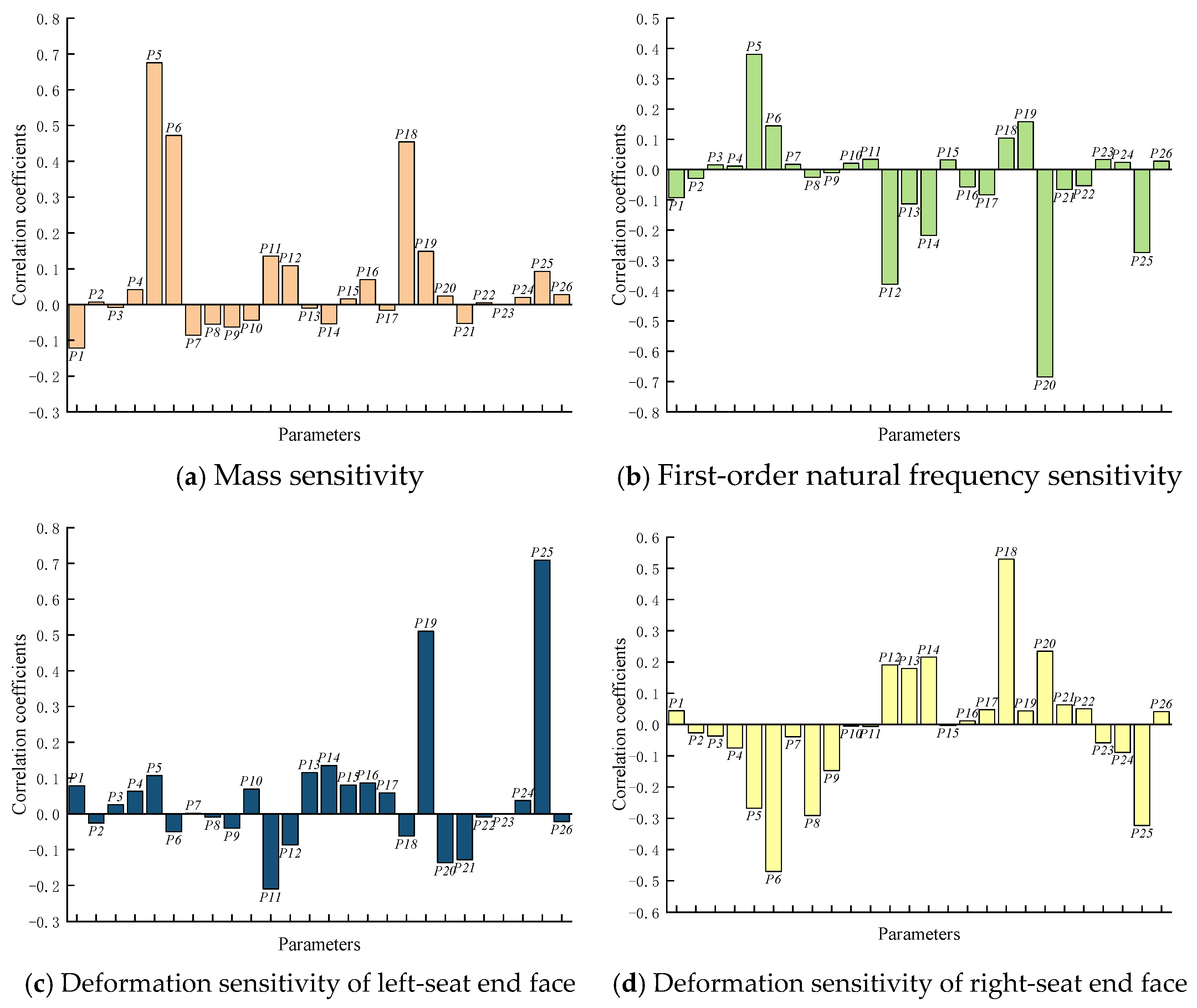
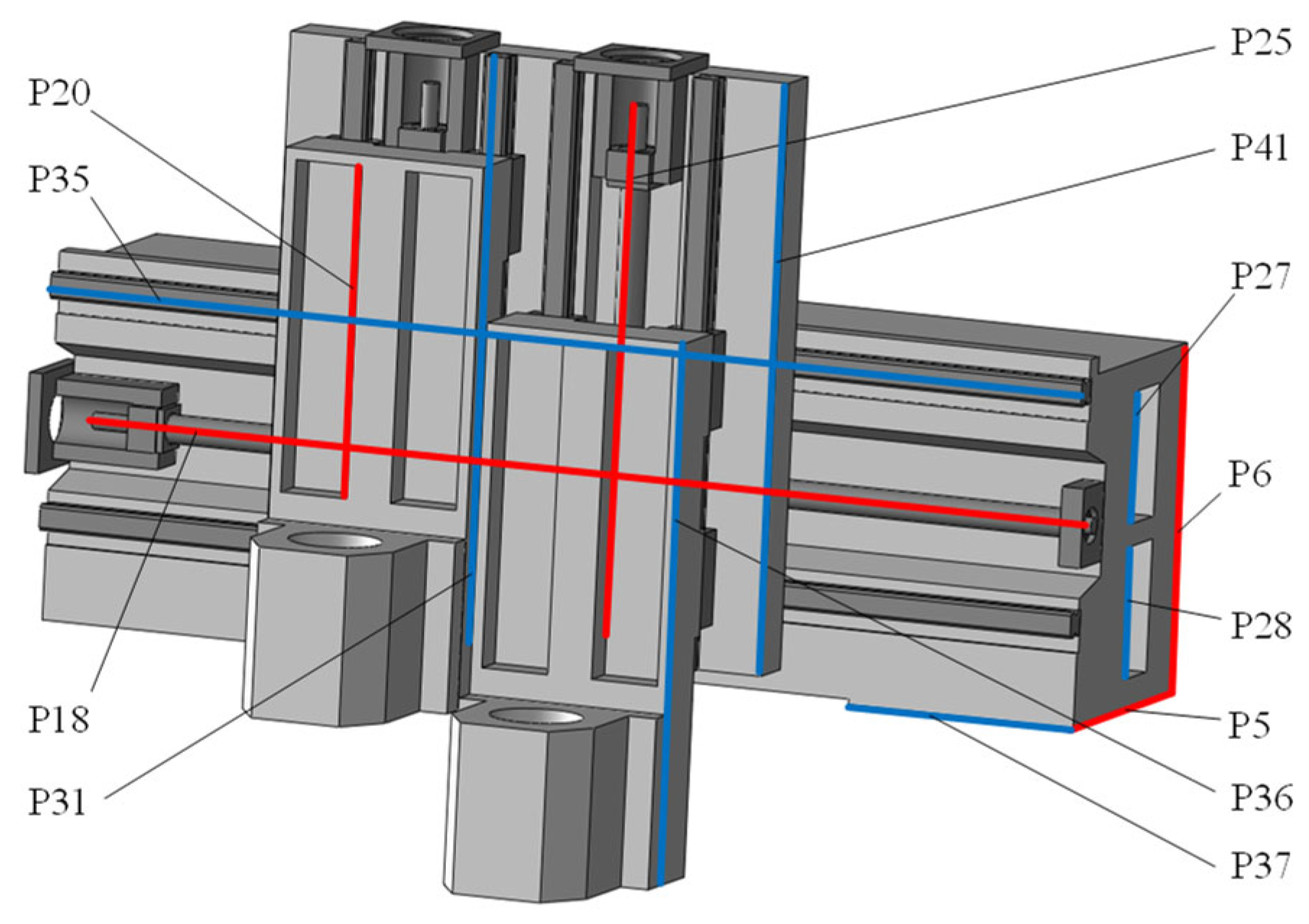
4.2. Parameter Sensitivity Analysis and Design Variable Selection

The mass, thermal–mechanical coupling deformation and first-order natural frequency of the dual-spindle component are jointly optimized as multi-objectives. The beam, Y-direction slide seat and Z-direction slide seat are the basic large parts constituting the main structure of the component [37]. Their large sizes and masses have an important impact on the performance of the CNC machine tool. In addition, the lead screw and nut as the heat source affect the thermal characteristics of the component significantly. Therefore, after filtering out sizes that are prone to interference, 26 optimized dimensions are initially selected from the beam, Y-direction slide seat, Z-direction slide seat, lead screw and spindle seat. The Spearman correlation analysis method is used to analyze parameter sensitivity. By repeatedly calling the coupled thermal–mechanical–vibration collaborative analysis mechanism, sensitivity analysis is conducted on the initially selected parameters. The correlation matrixes that can reflect the degree of correlation between various input parameters and selected optimization objectives are obtained. Figure 6 shows the correlation coefficients between parameters and optimization objectives.
As can be seen from Figure 6, P5 and P6 are the parameters with the largest sensitivity to mass and they are also sensitive to the rest of the objects. P18 is the parameter with the largest sensitivity to the coupling deformation of the right-spindle-seat end face and it is also very sensitive to the mass. P20 is the most sensitive to the first-order natural frequency and has a certain influence on the coupling deformation of the right-spindle-seat end face. P25 is the most sensitive to the coupling deformation of the left-spindle-seat end face. It also has a great influence on the first-order natural frequency and the coupling deformation of the right-spindle-seat end face. Considering the influence of each parameter on different optimization objectives, the five parameters such as P5, P6, P18, P20, P25 and their associated parameters are selected as design variables, as shown in Figure 7.
It is worth noting that the selected design variables have different positive and negative correlations with the three objectives. As is well known, the natural frequency is an important indicator affecting the mechanical stability of the component. The stability of the motorized spindle is stronger than that of the mechanical spindle. Due to the installation of two motorized spindles in the dual-spindle component, more attention is paid to the lightweight design and coupling deformation when the optimization objective needs to be balanced.
Since the structural configuration and size of the two spindles need to be the same, it is necessary to ensure that the design variables on the two spindle seats are consistent. In addition, the parameters with geometric constraints must ensure correlation relationships between them. The relationships between the selected design variables and the associated parameters are shown in Table 2.

5. Response Surface Building and Optimization Design

5.1. Central Composite Design

The change in design variables should not be too large because the large fluctuation may cause functional failure on each part or interference between different parts. However, in order to achieve the joint optimization of the mass, first-order natural frequency and thermal–mechanical coupling deformation, the design variables should have a large variation interval. Considering the above factors, the floating value of ± 10% of the original size is used as the upper and lower limits of the design variable. According to the CCD method and through analyzing the collaborative analysis mechanism repeatedly, a total of 27 experimental points are generated, as shown in Table 3.

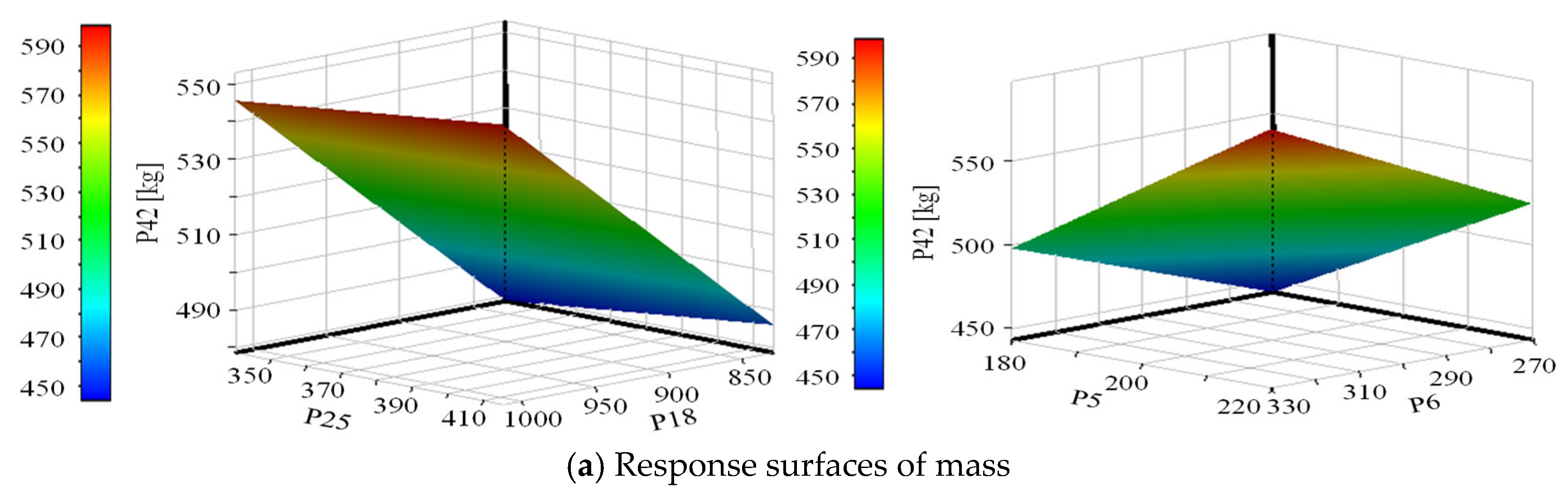
5.2. Response Surface Modeling

According to the sensitivity values of the design variables to the optimization objectives, the second-order response surfaces of the relationships between the design variables and the optimization objectives are established by the Kriging method, as shown in Figure 8. P42, P43, P44 and P45 represent the mass, the first-order natural frequency and the coupling deformation of the left- and right-spindle-seat end faces, respectively.
In this paper, the MOGA algorithm is used to extract sample points. Initially, 5000 samples are generated. Then, 1000 samples are generated in each iteration. The number of iterations is 20. Through repeatedlycalling the collaborative analysis mechanism and after 10,724 evaluations, three candidate points are obtained and validated. The response surface fitting values and validation values are shown in Table 4. We can see from the table that the correlation coefficients between the fitting values generated by the response surface and the validation values are all close to 1, which indicates a good fit. Before optimization, the mass of the dual-spindle component is 515.86 kg, the first-order natural frequency is 178.36 Hz, the coupling deformation of the left-spindle-seat end face is 80.10 μm, and the right-spindle-seat end face is 65.27 μm. Considering the requirement of a lightweight design and the influence of coupling deformation and natural frequency on machining accuracy, and after comparing the verification values in Table 4 with those before optimization, candidate point 2 is selected as the optimization result.

5.3. Analysis of Optimization Results

The design variables of the optimal candidate point 2 are used for re-simulation analysis by calling the coupled thermal–mechanical–vibration collaborative analysis mechanism again. The comparison of each objective before and after optimization is shown in Table 5. Optimized temperature distribution and thermal–mechanical coupling deformation after analysis are shown in Figure 9 and Figure 10.
It can be seen from Table 5 that the mass of the optimized dual-spindle component is 464.02 kg. which is 10.1% lower than the original 515.86 kg. The first-order natural frequency after optimization is 185.31 Hz, which improved by 3.9% compared to 178.36 Hz. Combining Figure 9 and Figure 10, it can be seen that the temperature of the component is basically unchanged, but the thermal–mechanical coupling deformation of the left- and right-spindle-seat end faces is 75.86 μm and 59.41 μm, which was reduced by 4.24 μm and 5.86 μm, respectively, from 80.10 μm and 65.27 μm before optimization.
To further examine the performance improvement of the component before and after optimization, the Z-direction coupling deformation along the surface centerlines of Z-direction slide seats and spindle seats is compared. Figure 11 shows the variation curve of the Z-direction coupling deformation of the left and right slide seats with the distance length from the top surface of the slide seats. Figure 12 shows the variation curve of the Z-direction coupling deformation of the left and right spindle seats with the distance length from the top surface of the spindle seats.
From Figure 11 and Figure 12, it can be seen that due to the different Z-values set for the left and right slide seat positions, the coupling deformations before and after optimization are different. Their amplitude of optimization also varies. Due to the increasing coupling deformation of the component along the Z-direction from the installation surface of the beam, the coupling deformation of the right Z-slide seat and the right spindle seat is smaller than that of the left seat because the Z-value of the right Z-slide seat position is smaller. This indicates that reducing the Z-coordinate of the machining point can reduce machining errors. On the other hand, under the premise of establishing synchronous and equivalent optimization of dual-spindle sizes, the optimization amplitude of the right Z-slide seat and the right spindle seat is greater. Based on the above analysis, it can be concluded that the larger the Z-direction range of the dual-spindle component, the better the optimization effect of the method proposed in this paper. This means that this method has good applicability for optimizing large gantry CNC machine tools.

6. Conclusions

In this paper, a multi-objective joint optimization design method based on coupled thermal–mechanical–vibration collaborative analysis is proposed. The dual-spindle component of the CNC machine tool is taken as the optimized object. By repeatedly calling the collaborative analysis mechanism during the optimization design process, five design variables are selected by the Spearman method, 27 experimental points are generated according to the CCD, the Kriging method is used to construct the response surface model, and the multiple objectives such as achieving a lightweight design, thermal–mechanical coupling deformation and first-order natural frequency of the dual-spindle component have been jointly optimized through the MOGA algorithm. The optimization results are as follows: after optimization, the mass of the dual-spindle component is reduced by 10.1%, the first-order natural frequency is increased by 3.9%, the coupling deformation of the left-spindle-seat end face is reduced by 5.3%, and the coupling deformation of the right-spindle-seat end face is reduced by 9.0%. The results indicate that the multi-objective joint optimization method based on coupled thermal–mechanical–vibration collaborative analysis improves the thermal, static and dynamic characteristics of the dual-spindle component synchronously and realizes the lightweight design. This method provides a reference for the multi-objective joint optimization design of CNC machine tools.

Author Contributions

Conceptualization, X.L.; Methodology, X.D.; Software, Y.X.; Validation, J.T.; Formal analysis, Y.H.; Supervision, P.W. All authors have read and agreed to the published version of the manuscript.

Funding

This research was financially supported by the National Natural Science Foundation of China (52175472; 62302263), Zhejiang Provincial Natural Science Foundation of China (LGG22E050031; LD24E050011; ZCLTGS24E0601) and Natural Science Foundation of Zhejiang Province for Distinguished Young Scholars (LR22E050002).

Data Availability Statement

Data are contained within the article.

Conflicts of Interest

Author Peng Wang was employed by Engine Factory of Sinotruk Jinan Power Co., Jinan Ltd. The remaining authors declare that the research was conducted in the absence of any commercial or financial relationships that could be construed as a potential conflict of interest.

References

  1. Wang, Y.T.; Wang, D.; Zhang, S.; Tang, Z.; Wang, L.; Liu, Y. Design and development of a five-axis machine tool with high accuracy, stiffness and efficiency for aero-engine casing manufacturing. Chin. J. Aeronaut. 2022, 35, 485–496. [Google Scholar] [CrossRef]
  2. Lajili, M.; Chanal, H.; Bouzgarrou, B.C. Machine tool architecture selection at the preliminary design stage: Application to hard material machining. J. Comput. Des. Eng. 2020, 7, 657–667. [Google Scholar] [CrossRef]
  3. O’Toole, L.; Fang, F.Z. Optimal tool design in micro-milling of difficult-to-machine materials. Adv. Manuf. 2023, 11, 222–247. [Google Scholar] [CrossRef] [PubMed]
  4. Yuksel, E.; Erturk, A.S.; Budak, E. A Hybrid Contact Implementation Framework for Finite Element Analysis and Topology Optimization of Machine Tools. J. Manuf. Sci. Eng.-Trans. Asme 2020, 142, 081001. [Google Scholar] [CrossRef]
  5. Huang, W. Multi-Step Optimization Design of Weak Structural Parts of Machine Tools. Master’s Thesis, Shanghai Jiao Tong University, Shanghai, China, 2021. [Google Scholar]
  6. Liu, S.H.; Du, Y.B.; Lin, M. Study on lightweight structural optimization design system for gantry machine tool. Concurr. Eng.-Res. Appl. 2019, 27, 170–185. [Google Scholar] [CrossRef]
  7. Ding, Y.Y.; Rui, X.; Chang, Y.; Lu, H.; Chen, Y.; Ding, J.; Shehzad, A.; Chen, G.; Gu, J. Optimal design of the dynamic performance of the ultra-precision fly cutting machine tool. Int. J. Adv. Manuf. Technol. 2023, 124, 567–585. [Google Scholar] [CrossRef]
  8. Yang, J.S.; Zhou, Z.W.; Lin, X.L.; Deng, X.L.; Wang, J.C.; Zheng, Y.N. Multi-objective joint optimization design of high-precision turn-milling compound machine tool bed based on nonparametric regression response surface method. Manuf. Technol. Mach. Tool 2024, 5, 128–133. [Google Scholar]
  9. Chang, T.H.; Chen, S.L.; Kang, C.A.; Inasaki, I. Design optimization of the linkage dimension for a hybrid-type parallel kinematic machine tool. Proc. Inst. Mech. Eng. Part K-J. Multi-Body Dyn. 2002, 216, 143–156. [Google Scholar] [CrossRef]
  10. Zhai, L.X.; Sun, J.J.; Ma, X.; Han, W.T.; Luo, X.S. Thermal-structure coupling analysis and multi-objective optimization of motor rotor in MSPMSM. Chin. J. Aeronaut. 2019, 32, 1733–1747. [Google Scholar] [CrossRef]
  11. Chen, G.; Guo, S.J.; Ding, Q.Q.; Su, Z.; Tang, S.F. SHO-LSTM predictive modeling of spindle thermal error of CNC lathe. Adv. Eng. Sci. 2024, 56, 277–288. [Google Scholar]
  12. Guo, Z.Z.; Zhang, Y.S.; Liu, S.H. The Finite Element Analysis and the Multi-Objective Optimization Design of Spindle Systems of CNC Gantry Machine Tools. Key Eng. Mater. 2016, 693, 243–250. [Google Scholar] [CrossRef]
  13. Ouyang, X.L.; Xu, R.N.; Jiang, P.X. Three-equation local thermal non-equilibrium model for transient heat transfer in porous media: The internal thermal conduction effect in the solid phase. Int. J. Heat Mass Transf. 2017, 115, 1113–1124. [Google Scholar] [CrossRef]
  14. Zhang, C. Study on Thermal-Structural Coupling Simulation Analysis of Spacecraft. Master’s Thesis, Shanghai Jiao Tong University, Shanghai, China, 2021. [Google Scholar]
  15. Deng, X.L.; Fu, J.Z.; He, Y.; Chen, Z.C. Multi-physics coupling thermal characteristics of precision CNC machine tool spindle system. J. Zhejiang Univ. (Eng. Sci.) 2013, 47, 1863–1870. [Google Scholar]
  16. Wu, S.; Liu, T.; Liu, X.; Li, C.; Wang, C. Analysis of dynamic characteristic field of five-axis machine tool based on Kriging method. J. Vib. Meas. Diagn. 2022, 42, 68–75. [Google Scholar]
  17. Zhao, W.L. Research on Thermal-Mechanical Coupling Analysis and Optimization Design of Large CNC Machine Tool Workbench. Master’s Thesis, Hainan University, Haikou, China, 2021. [Google Scholar]
  18. Li, Z.J.; Zhao, C.Y.; Wen, B.C.; Lu, Z.C. Heat Source Rate Identification and Thermal Error Predictions of Ball Screw Feed Drive System for CNC Machine Tools. J. Northeast. Univ. 2019, 40, 1305–1309. [Google Scholar]
  19. Shen, J.X.; Xu, P.; Yu, Y.H.; Zheng, S.X. Optimization design and comprehensive performance analysis of BFPC machine tool gantry frame assembly. J. Mech. Eng. 2019, 55, 127–135. [Google Scholar] [CrossRef]
  20. Huang, H.Q.; Liu, H.L.; Wang, Y.; Huang, H.W.; Jiang, L.L. Stress-strain and modal analysis of marine centrifugal pump rotor based on fluid-solid coupling. Trans. Chin. Soc. Agric. Eng. 2014, 30, 98–105. [Google Scholar]
  21. Ye, H.; Gao, Y.; Liu, J.; Zhang, J.; Li, L.; Liu, X.B.; Liu, S.C.; Dong, G.X.; Jiang, F.L.; Guo, J.H. Optimization of Beam Dynamic Characteristics Based on Vibration Velocity and Noise. J. Hunan Univ. Nat. Sci. 2024, 51, 219–226. [Google Scholar]
  22. Amman, M.; Rashid, T.; Ali, A. Fermatean fuzzy multi-criteria decision-making based on Spearman rank correlation coefficient. Granul. Comput. 2023, 8, 2005–2019. [Google Scholar] [CrossRef]
  23. Zhang, D.H.; Yang, Y.C.; Liu, Y.M.; He, J. Hybrid DC line pilot protection method based on EMD and Spearman correlation coefficient. Power Syst. Prot. Control 2021, 49, 1–11. [Google Scholar]
  24. Issa, M.A.; Abidin, Z.Z.; Sobri, S.; Abdul-Rashid, S.; Mahdi, M.A.; Ibrahim, N.A.; Pudza, M.Y. Fabrication, characterization and response surface method optimization for quantum efficiency of fluorescent nitrogen-doped carbon dots obtained from carboxymethylcellulose of oil palms empty fruit bunch. Chin. J. Chem. Eng. 2020, 28, 584–592. [Google Scholar] [CrossRef]
  25. Liu, J.; Wang, K.L.; Lu, S.Q.; Li, X.; Huang, W.J.; Zeng, Q.; Zhou, T.; Wang, Z.Q. Optimization of deformation process parameters of Ti_2AlNb-based alloy based on response surface method. Rare Met. Mater. Eng. 2023, 52, 3581–3589. [Google Scholar]
  26. Deng, C.; Miao, J.; Yang, S.; Yin, G.; Wei, B. The Spatial Cutting Stability of CNC Machine Tool Based on Kriging Model. J. Vib. Meas. Diagn. 2019, 39, 495–502. [Google Scholar]
  27. Veerakumar, R.; Raul, V.; Liu, Y.; Wang, X.; Leifsson, L.; Hu, H. Metamodeling-based parametric optimization of DBD plasma actuation to suppress flow separation over a wind turbine airfoil model. Acta Mech. Sin. 2020, 36, 260–274. [Google Scholar] [CrossRef]
  28. Wan, Y.F.; Sun, W.L.; Wang, H.W.; Xu, T.T.; Wang, B.J. Lightweight design of wind turbine spindle based on Kriging model and MOGA algorithm. Acta Energiae Solaris Sin. 2022, 43, 388–395. [Google Scholar]
  29. Zhang, Y.M.; Bao, F.X.; Qi, P.N. Modeling method for thermal characteristics of ball screw nut pair. China Mech. Eng. 2020, 31, 2486–2490, 2496. [Google Scholar]
  30. Yang, X.F.; Shi, Y.; Xu, Y.; Li, Z.R. Influence of screw-nut preload on thermal characteristics of machine tool feed system. Mod. Manuf. Eng. 2019, 117–123. [Google Scholar]
  31. Shao, L.Z. Thermal Deformation Analysis and Structural Optimization of Five-Axis Gantry Machining Center. Master’s Thesis, Southeast University, Nanjing, China, 2018. [Google Scholar]
  32. Yang, X.; Zeng, L.W.; Chen, P.; Li, B. Complex heat flow characteristics and multi-dimensional control strategy of dry-cutting hobbing machine. China Mech. Eng. 2022, 33, 623–629. [Google Scholar]
  33. Jin, Y.L.; Yu, Q.; Wang, D.D.; Cheng, Y.; Zhang, X.M. Research on convective heat transfer coefficient of ball screw in machining center. Mach. Tool Hydraul. 2020, 48, 37–39. [Google Scholar]
  34. Lai, K.X.; Cao, H.J.; Li, H.C.; Li, B.J.; Huang, D.S. Coupling evaluation for material removal and thermal control on precision milling machine tools. Front. Mech. Eng. 2022, 17, 12. [Google Scholar] [CrossRef]
  35. Chang, J.T.; Liu, Y.; Kong, X.G.; Li, X.W.; Chen, Q.; Su, X. Prediction method of cutting force under variable working conditions based on geometric features of workpiece. J. Xidian Univ. 2022, 49, 154–165. [Google Scholar]
  36. Guo, R.L.; Deng, W.Q.; Li, D.L. Optimization design and performance analysis of CNC machine tool composite structure bed based on grey theory. J. Lanzhou Univ. Technol. 2021, 47, 53–58. [Google Scholar]
  37. Chen, Y.I.; Qiu, Z.H.; Guo, J.K.; H, J.; Liu, Z.G. An optimization method for the quality of basic large parts of machine tools in the conceptual design stage. J. Xi’an Jiaotong Univ. 2017, 51, 105–114. [Google Scholar]
Figure 1. The flow chart of optimization based on coupled thermal–mechanical–vibration collaborative analysis.
Machines 12 00885 g001
Figure 2. Dual-spindle component structure.
Machines 12 00885 g002
Figure 3. Boundary conditions.
Machines 12 00885 g003
Figure 4. Temperature distribution.
Machines 12 00885 g004
Figure 5. Thermal–mechanical coupling deformation.
Machines 12 00885 g005
Figure 6. Correlation coefficient between parameters and optimization objectives.
Machines 12 00885 g006
Figure 7. Distribution of design variables.
Machines 12 00885 g007
Figure 8. Response surfaces of the optimization objectives.
Machines 12 00885 g008aMachines 12 00885 g008b
Figure 9. Optimized temperature distribution.
Machines 12 00885 g009
Figure 10. Optimized thermal–mechanical coupling deformation.
Machines 12 00885 g010
Figure 11. Deformation comparison of slide seats.
Machines 12 00885 g011
Figure 12. Deformation comparison of spindle seats.
Machines 12 00885 g012
Table 1. Material properties.
MaterialsDensity/
(kg/m3)
Elastic Modulus
/MPa
Poisson RatioThermal Conductivity/(W/(m·K))Thermal Expansion Coefficient
/(°C−1(10−5))
HT300730013,0000.25501.2
45 (modulated)7850210,0000.31481.15
Cronidur 307670210,0000.3014.51.05
Table 2. Design variables and correlation relationships.
Design VariablesAssociated ParametersCorrelation Relationships
P5NullNull
P6P27, P28P27= (P6 − 2 × P4 − P3)/2 + 12.5 = P28
P18P35, P36P35 = P18 + 122, P36 = (P18−818)/2
P20P37P37 = P12 + P20 + P22 + 20
P25P31, P41P31 = P25 + 142 = p41
Table 3. Central composite designs’ experimental points.
Serial NumberP5/mmP6/mmP18/mmP20/mmP25/mmMass/kgFirst-Order Natural Frequency /HzThermal–Mechanical Coupling Deformation of the Left End Face /μmThermal–Mechanical Coupling Deformation of the Right End Face /μm
1200300920300378515.85178.3680.0965.26
2180300920300378470.60169.2378.4968.58
3220300920300378561.11185.2982.0463.18
4200270920300378483.89173.6081.5269.06
5200330920300378547.81180.4680.1260.49
6200300828300378482.34176.4881.8860.03
72003001012300378549.37179.5479.7971.77
8200300920270378512.70191.9882.8162.55
9200300920330378519.01161.8178.1169.02
10200300920300340.2512.18180.0474.4970.92
11200300920300415.8519.53169.8791.9061.46
12194.33291.49893.93291.49388.71485.58176.3383.6163.45
13205.66291.49893.93291.49367.28507.78185.2979.7364.32
14194.33308.50893.93291.49367.28500.35181.8878.2763.27
15205.66308.50893.93291.49388.71528.14183.1184.7660.20
16194.33291.49946.06291.49367.28501.31181.0978.3369.89
17205.66291.49946.06291.49388.71528.94182.0983.8865.42
18194.33308.50946.06291.49388.71521.31179.1282.7164.19
19205.66308.50946.06291.49367.28546.27188.1378.8065.20
20194.33291.49893.93308.50367.28485.29171.6477.4768.04
21205.66291.49893.93308.50388.71511.65172.7383.3363.75
22194.33308.50893.93308.50388.71504.22170.4082.0562.67
23205.66308.50893.93308.50367.28527.85177.5978.1363.86
24194.33291.49946.06308.50388.71505.18169.5381.6168.84
25205.66291.49946.06308.50367.28528.64176.5478.1369.99
26194.33308.50946.06308.50367.28521.01174.1576.5969.22
27205.66308.50946.06308.50388.71550.14175.0782.2564.52
Table 4. Candidate points to verify the comparison.
PerformanceMass/kgFirst-Order
Natural
Frequency/Hz
Thermal–Mechanical Coupling Deformation of the Left End Face/μmThermal–Mechanical Coupling Deformation of the Right end Face/μm
Point 1Point 2Point 3Point 1Point 2Point 3Point 1Point 2Point 3Point 1Point 2Point 3
Fitting values464.29464.52464.82185.19185.47185.2575.1975.2175.1258.8058.9158.98
Validation values464.42464.63464.95185.05185.37185.1575.9075.8875.7859.2959.3959.47
Correlation coefficients0.99970.99980.99970.99920.99950.99950.99060.99120.99120.99170.99190.9918
Table 5. Comparison of objectives before and after optimization.
PerformanceMass
/kg
First-Order Natural Frequency/HzThermal–Mechanical Coupling Deformation of the Left End Face/μmThermal–Mechanical Coupling Deformation of the Right End Face/μmTemperature/°C
Original values515.86178.3680.1065.2740.384
Optimized values464.02185.3175.8659.4140.568
Rate of change/%10.13.95.39.00.4
Disclaimer/Publisher’s Note: The statements, opinions and data contained in all publications are solely those of the individual author(s) and contributor(s) and not of MDPI and/or the editor(s). MDPI and/or the editor(s) disclaim responsibility for any injury to people or property resulting from any ideas, methods, instructions or products referred to in the content.

