1. Introduction
Industrial automation is a multidisciplinary field that requires expertise in various engineering sectors. Currently, the application of industrial automation has transformed into a digital infrastructure that automates and simplifies the daily life of industrial engineers. In the pursuit of digital transformation in production, industrial control units are at the center of the departure from old systems and tend to move towards the advantages of new technology that guarantee faster communication between all objects involved [
1,
2,
3]. For such an application of Industry 4.0, it is necessary to use a large number of intelligent objects that require reconfiguration and connection with all industrial products and services [
4]. Industry 4.0 can be understood as a set of technologies capable of performing machine operations without significant human intervention. Among such systems, we can include PLC programmable devices, HMI panels (Human Machine Interface), SCADA visualization, robots, and others. By configuring such constantly evolving devices, we prove their ease of implementation in various industrial applications [
5].
Currently, we are witnessing a rapid advancement in technological progress in the field of additive technologies, which has undergone significant development and has become an integral part of many branches of production. Simultaneously with the development of 3D printing, we are witnessing the rise of so-called smart technologies, such as the Internet of Things (IoT), PLC control, artificial intelligence (AI), augmented reality (AR), and others [
6]. These technologies bring new possibilities and opportunities for improving and optimizing 3D printing processes. Technological progress in the field of 3D printing has been significant in recent years and has brought us a number of innovations and solutions that significantly expand the possibilities and applications of this technology. It is obvious that the use of additive manufacturing technologies in industry will increase in the future [
7].
3D printing has become a revolutionary tool in manufacturing, enabling the creation of complex geometric shapes with high efficiency and speed [
8,
9,
10]. However, with 3D printing, various problems often can affect the quality of the print and the final product. These problems can be caused by a variety of factors, including printer settings, materials used, or the complexity of the model’s shape. Errors in 3D printing can arise for many reasons and have different consequences on the final printed model. One of the main issues associated with this technology is the dimensional accuracy of the resulting products. Dimensional accuracy directly impacts the functionality and quality of 3D printed components, which is critical, especially in industrial applications [
11,
12,
13]. It is important to recognize these errors and their causes to correct them effectively. The most common errors in 3D printing include warping, stringing, over extrusion, under extrusion and layer shifting.
The goal of this article is to describe the creation of a scanning measuring device powered by a servo motor, which is controlled through a programmed PLC system with a compatible control system for a servomotor that can also be applied to various sliding and rotating movements of machines. Subsequently, the complex system designed in this way will be verified by simulation and direct testing in the laboratory conditions. This article briefly explains the given PLC system, considering its application in industrial automation. It also provides an overview of the most important characteristics and advantages of devices from Rockwell Automation, which were directly used in the design of the control system. It also provides information not only about the design process of the control program but also about the individual structural instructions that perform the basic actions of the servo motor. Subsequently, the results of the work are declared by the possibilities of application of the designed management program directly in practice.
In conclusion, the PLC-controlled scanning system is compared with other available object digitization solutions. As a result of these activities, a complex system has been created for in-depth scanning of parts, primarily created by 3D printing, to detect component surface defects and monitor the quality of the parts associated with the additive manufacturing process.
2. State of the Art
3D printing is increasingly used in various fields, but methods to measure and quantify the quality of printed objects are still limited, especially for very small, large, or fragile objects. The design of measurement systems can play a key role in monitoring and optimizing the quality of 3D printed products. In recent years, scanning devices based on the principle of depth scanning have proven to be an effective tool for measuring the geometric properties of 3D printed parts [
14]. These scanners enable fast and accurate measurement of details, leading to more accurate evaluation of dimensional characteristics compared to traditional methods. Various measurement methods, as well as analysis techniques, can be applied to evaluate dimensional deviations [
15,
16]. Improving dimensional accuracy can lead to reduced waste and increased economic efficiency in manufacturing processes [
17].
Scanning technologies are constantly evolving, with modern depth scanners using advanced algorithms to process 3D data. These devices allow for immediate data processing and feedback, which increases the ability to respond quickly to any deviations and increases measurement accuracy. Furthermore, the correct setup and calibration of the axes and depth scanner can significantly affect the measurement results, which emphasizes the importance of choosing the right hardware and software. A PLC-controlled measurement system allows for the integration of scanning technologies into industrial processes, ensuring automation of measurement sequences and reducing the risk of human error. The use of PLC guarantees flexibility and adaptability in the measurement system based on the specific requirements of the manufacturing process.
In the study of Kwangwoo et al., a 3D structured light system (3D-SLSS) was used for the first time for non-contact and non-destructive evaluation of the print quality of clay objects with various visual defects. The results showed that all printed samples had differences between measured and designed values. 3D-SLSS proved to be a simple and fast method for quality control in various industrial applications [
18]. The paper by Fastowicz et al. proposes an automated assessment of the surface quality of 3D printed objects based on the analysis of depth maps, which allows the identification of problems during printing and potential modification of the process. The application of entropy analysis to 3D scans provides an independent assessment of surface regularity regardless of filament color, while the obtained results indicate the possibilities of further combining it with camera-based methods [
19]. 3D printing has evolved from a laboratory prototyping technology to an industrial production method, becoming essential for creating functional objects. Slot et al. introduce an innovative, non-contact microwave sensor designed for rapid and cost-effective defect detection in printed components, addressing both mechanical errors and conductivity inhomogeneity. The sensor’s methodology and results demonstrate precise fault detection and easy integration with various types of 3D printers [
20]. Reverse engineering is essential for recovering design knowledge that is lost or obsolete, and 3D scanning technologies have transformed the techniques used for this process. The paper of Helle et al. reviews the literature on the methodologies and challenges of using 3D scanning for reverse engineering and production control, supplemented by a case study involving a handheld 3D laser scanner. The findings reveal that while 3D scanning is effective for complex geometries, significant challenges remain in developing accurate surface reconstruction algorithms to address point cloud imperfections [
21]. The research of Hegedus et al. presents a framework that utilizes advanced 3D scanning and data analysis techniques to identify and classify welding defects by comparing high-resolution point clouds of welded parts to reference models. While effective in detecting various defect types, its performance is influenced by scanning quality and environmental conditions, highlighting the need for future improvements [
22]. Lin et al. developed an online quality monitoring system for material extrusion additive manufacturing, using laser scanning technology to detect defects like overfill and underfill by comparing surface point clouds to ideal CAD models. Experimental validation shows the system’s effectiveness in detecting, quantifying, and reconstructing 3D models of defects, offering valuable feedback for minimizing material waste and improving manufacturing quality [
23]. The research of Li et al. aims to improve quality assessment in Fused Deposition Modeling (FDM) additive manufacturing by using machine learning and deep learning techniques to predict dimensional deviations between CAD designs and printed parts based on sensor data. The study employs an optical 3D scanner and various algorithms to analyze surface quality and correlate process parameters, enhancing the accuracy and reliability of print quality assessments [
24]. The use of 3D scanning technology was also described in the article by Afteni et al. They used the GOM ATOS Core scanner to assess the dimensional accuracy of machined components, finding significant advantages over traditional measurement techniques in terms of accuracy and time efficiency. The results indicate that 3D scanning can significantly improve product development and process optimization in industrial applications [
25]. Montalti et al. examine the geometric and dimensional accuracy of PLA parts produced via material extrusion additive manufacturing by comparing them to their original STL models using a mid-range 3D scanner. The findings indicate effective control over most features, with higher deviations observed in small details, and emphasize the feasibility of using accessible 3D scanning technologies for cost-effective accuracy assessment [
26].
Depth scanners are capable of achieving measurement accuracy in the micrometer range, making them an ideal solution for applications with high precision requirements. Research in this area has shown that optimizing scanning processes and subsequent data analysis can lead to significant improvements in the quality of 3D printed products.
3. Design of Scanning System
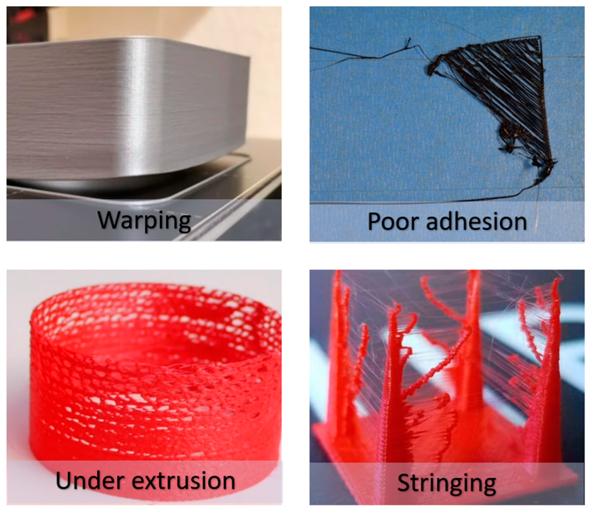
FDM/FFF printing is one of the most widely used technologies in additive manufacturing, mainly due to the wide choice of materials, printers, and user availability. Most recent experiments focus on the use of FFF printing in various branches of technical practice. For this reason, current research is focused on monitoring mechanical properties, testing and combining new materials, and quality control of printed products. Among the main shortcomings that arise during FFF printing are the following (
Figure 1):
Warping: this is a very common error in FFF printing. It occurs due to peeling and twisting of layers or corners of the printed object, which can be caused by rapid cooling of the printed filament or insufficient adhesion to the printing pad. This type of deformation is mainly observed in materials such as ABS, Nylon, and ASA, which are more prone to rapid cooling and require a heated printing chamber.
Poor adhesion: insufficient adhesion leads to loosening, deformations, and low surface quality of the printed object. Insufficient adhesion can be caused by a poorly calibrated printing pad, an inappropriately chosen printing temperature for the selected material, or a poorly cleaned printing pad. Various adhesives can be used to increase adhesion or support material can be used to “slice” the model.
Stringing: it is an error in which there is an unwanted outflow of thermoplastic material from the nozzle, resulting in the formation of hairpins, which are subsequently connected to the printed parts of the component. These errors arise for several reasons, such as a high nozzle temperature for the given material, too fast retraction of the material when moving the print head, or too short a retraction distance.
Under extrusion: with FFF printing, there can be problems with the extrusion of the material, which can result in peeling and the formation of pores between the individual layers. This type of problem arises when the nozzle is damaged or heavily soiled or when the material is fed at a low speed. The opposite of under extrusion is over extrusion, where the material is excessively extruded.
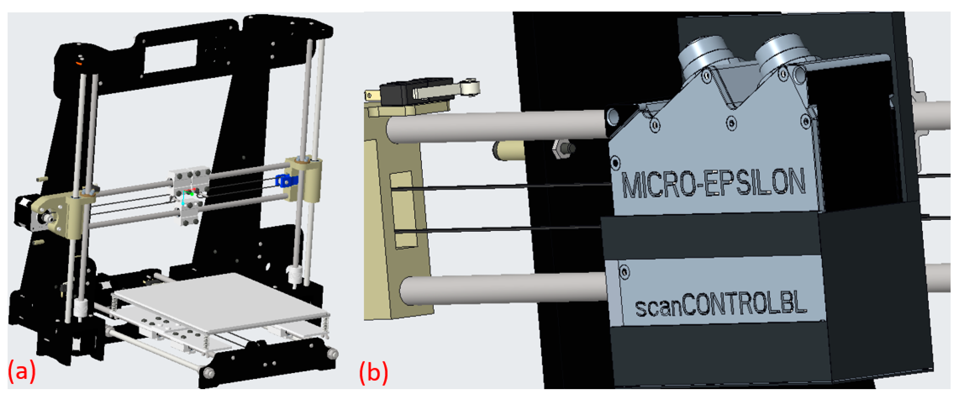
The design of the proposed measuring system is based on the frame of the Anet A8 3D printer, which has a printing space of 220 × 220 × 240 mm. The structure has been significantly modified structurally and mechanically from the original purpose of 3D printing. From a construction point of view, several reinforcing elements were added to the printer to prevent movement along the axes without increased vibrations that could affect the accuracy of the measuring system. The construction of the measuring system presented in
Figure 2a has two threaded rods for movement along the Z-axis, which allows for more precise adjustment of the used depth sensor. The original NEMA 17 stepper motor was not a suitable solution for this purpose in terms of setting accuracy and smoothness of movement. For this reason, the Allen-Bradley Kinetix TLP-A046 servomotor was used as a suitable alternative, which uses a digital encoder for positioning and smooth operation. By using such a servomotor controlled by a servo drive in connection with a PLC, it is possible to achieve higher positioning accuracy and fluency during the subsequent scanning of the surface of the components. The smoothness and accuracy of the movement settings of the measuring scanning device have a direct impact on the resulting quality of the scanned objects. For mounting the selected depth sensor, a fixture was designed to fix it on the X-axis, presented in
Figure 2b.
In the presented design of the measuring scanning system, a depth sensor from Micro-Epsilon scanCONTROL BL 25x0-25 was used. The depth sensor works on the principle of laser triangulation. Laser triangulation is a 3D detection algorithm commonly used in industrial vision. It is a machine vision technology that processes 3D measurement data by pairing a laser light source with a camera. The laser transmitter emits a parallel laser beam and spreads it through the cylindrical lens. Because it provides high resolution and accuracy, it can be used in many high-speed applications. The selected depth sensor uses a more powerful blue laser light for scanning with a measurement range of 25 mm along the Z-axis. Blue laser light is used to scan shiny surfaces or metal materials. For this reason, this type of sensor is widely used in industry for 3D inspection, e.g., welding joints, dimensional control, and compliance with tolerances. The sensor has a high sampling frequency of up to 2000 Hz and a resolution of 2 μm along the Z axis.
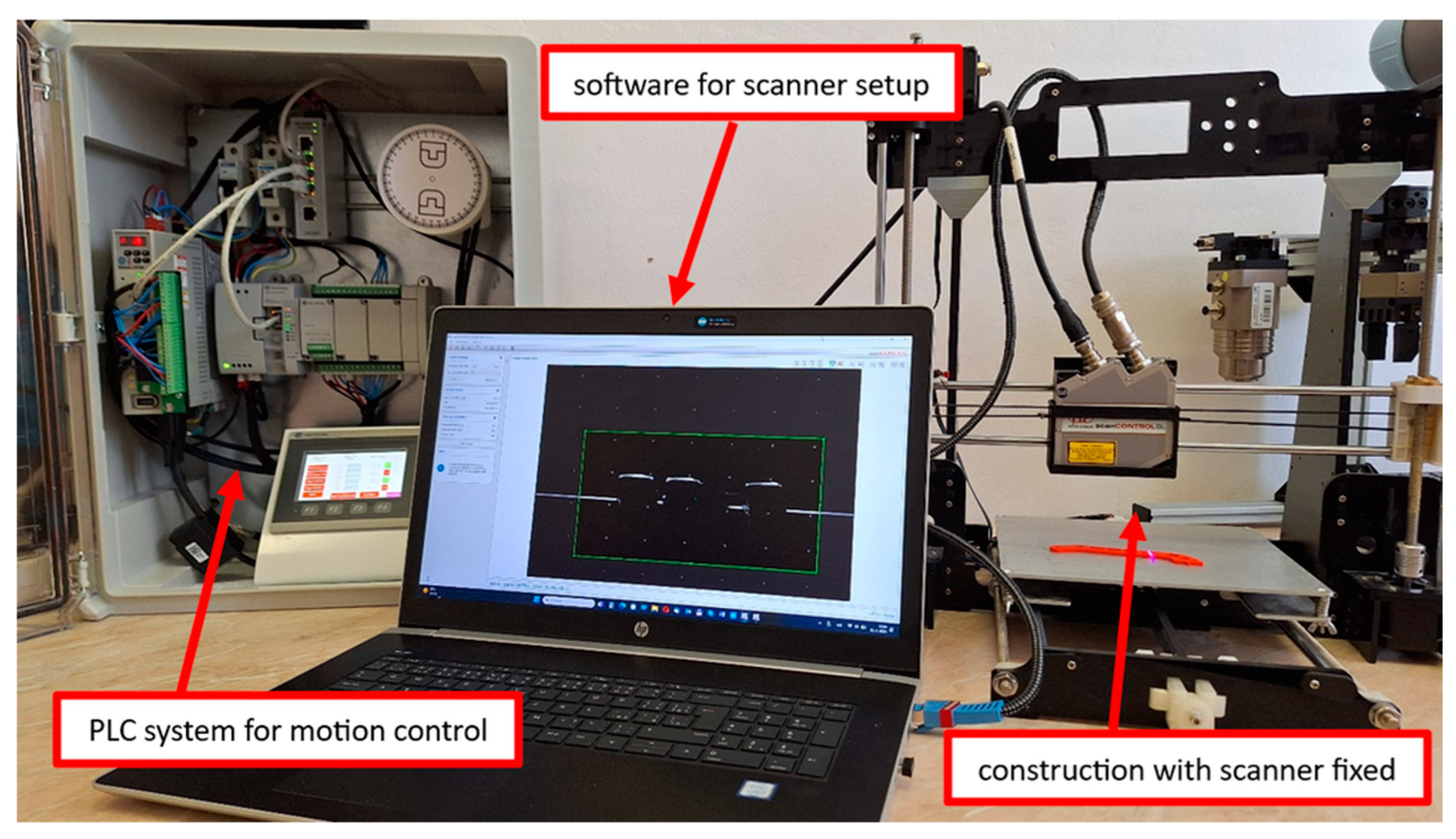
Figure 3 shows the composition of the measuring workplace, which consists of a computer with the control software of the depth sensor, a PLC system, a servo drive for controlling the servomotor, and the structure itself with an attached sensor. Two supporting software tools, SCANcontrol ver. 6.9 and SCAN3Dcontrol ver. 3.8, were used to control the depth sensor.
The SCANcontrol software ver. 6.9 is used to make basic connections and set the depth sensor. In this software, the sensor is connected to the computer using an RJ-45 network connector. It is then possible to set the scanning parameters directly in the software, such as the angle relative to the measuring pad, the scanning speed, the scanning area, the threshold, etc. The output from the scan in this software is a file in AVI format. The second software used is SCAN3D control ver. 3.8, which serves to display the data obtained from the SCANcontrol software. In the software, it is possible to view and check the scanned object with the available measuring tools.
4. Used Hardware Devices for Motion Control of the Proposed Measuring System
To create a compact control system, we used intelligent devices from Rockwell Automation. These are fully integrated automation system devices with a high degree of flexibility to adapt to various tasks. Due to their simplicity, they are intended not only for production spheres but also for academic institutions for various research purposes. With their features, these devices offer a high degree of security and stability.
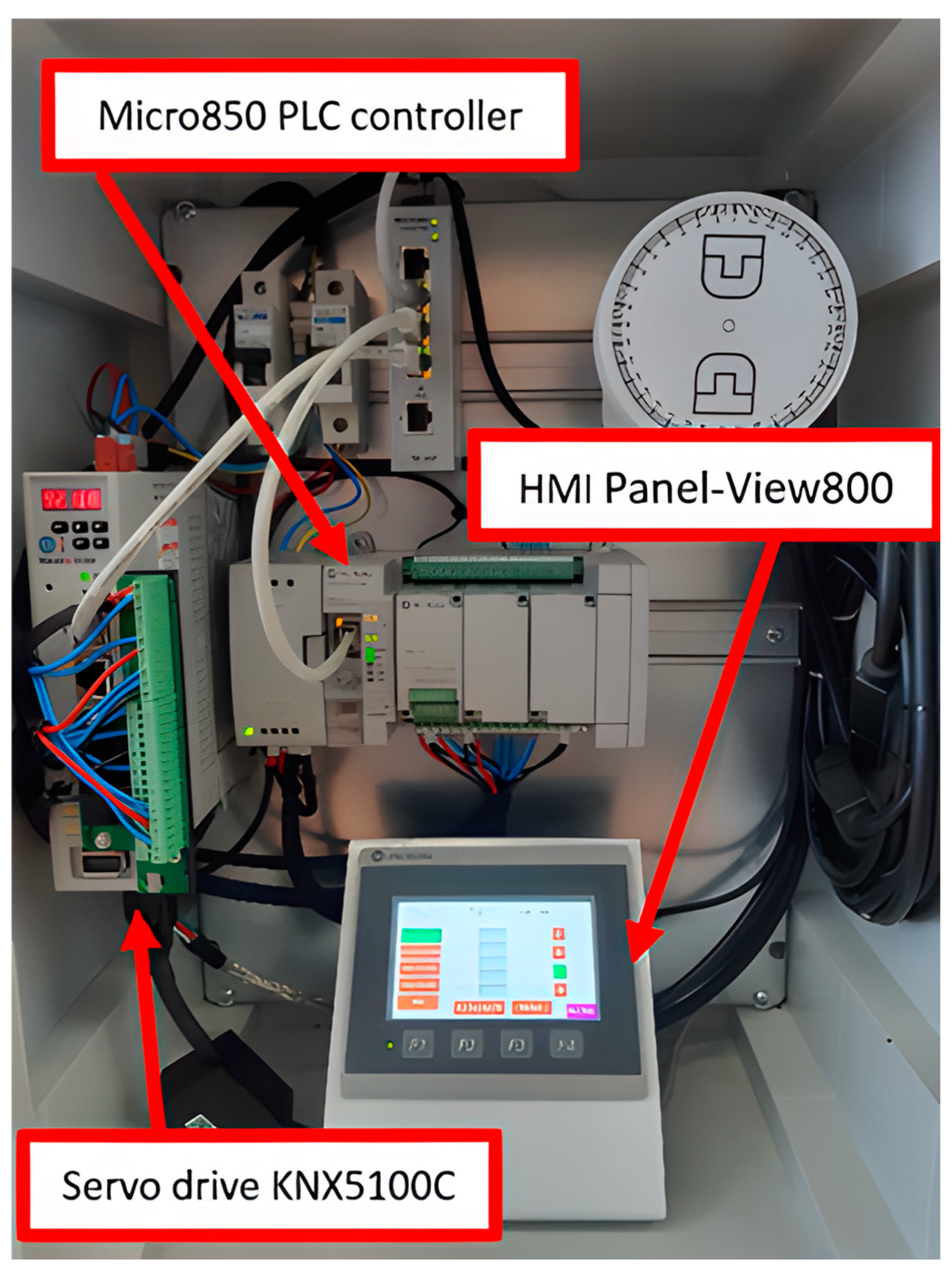
The Micro 850 PLC system (
Figure 4), combined with the Allen-Bradley Panel-View800 control panel and the Allen-Bradley Kinetix5100 servomotor with TLP drive, was used to design the precise movement of the measuring system.
The main advantages of the devices/equipment used in the design of the measuring system:
thanks to the simple connection to the network, relatively shorter times are achieved for development and productivity improvement;
programming takes place on a homogeneous platform through the Connected Components Workbench (CCW) software,
scalability and reusability are achieved through shared codes;
variables can be created using HMI tags;
offers global and multilingual support.
This fully integrated automation solution is used in various productions or energy plants and is suitable for performing common automatic tasks, such as material handling, assembly, packaging, and the precise control of a number of other applications.
A Allen-Bradley PanelView800 touchscreen was used to control the movement of the TLP motor in the measuring system and to determine the required parameters. This touchscreen features high resolution and a color depth of up to 65K. Its system security is bolstered by a robust 800 MHz processor with 256 MB of memory, ensuring smooth user interaction. Updates to the panel or data collection during operations can be performed via a USB port or micro SD slot. Connectivity with other control systems is facilitated through Ethernet and serial ports that support various communication protocols. The switchboard is programmed using Connected Component Workbench (CCW) development software, and a key advantage is the ability to convert applications from older models of these control panels.
The Allen-Bradley Kinetix5100 servo drive is designed to offer a complete motion control solution for small to medium machines when paired with a Allen-Bradley Kinetix TLP servo motor. This configuration provides an innovative and competitive solution for machine manufacturers, as the Kinetix5100 is a versatile servo drive with a wide range of power supply and control modes. Due to their superior performance, these servo drives can operate independently or alongside a Micro850 control system. Several performance versions are available, and users can select the type that meets their needs. The Kinetix5100 also has an STO function, which represents an emergency disconnection of the motor’s torque, allowing the servo drive to remain connected to the power supply.
5. Implementation of the Proposed Solution
The design and implementation of the control program are based on the connection of individual devices that are necessary for the execution of the control program. A PLC rack was designed to fix and assemble individual control systems. The achieved assembly layout of all devices and components is shown in
Figure 5.
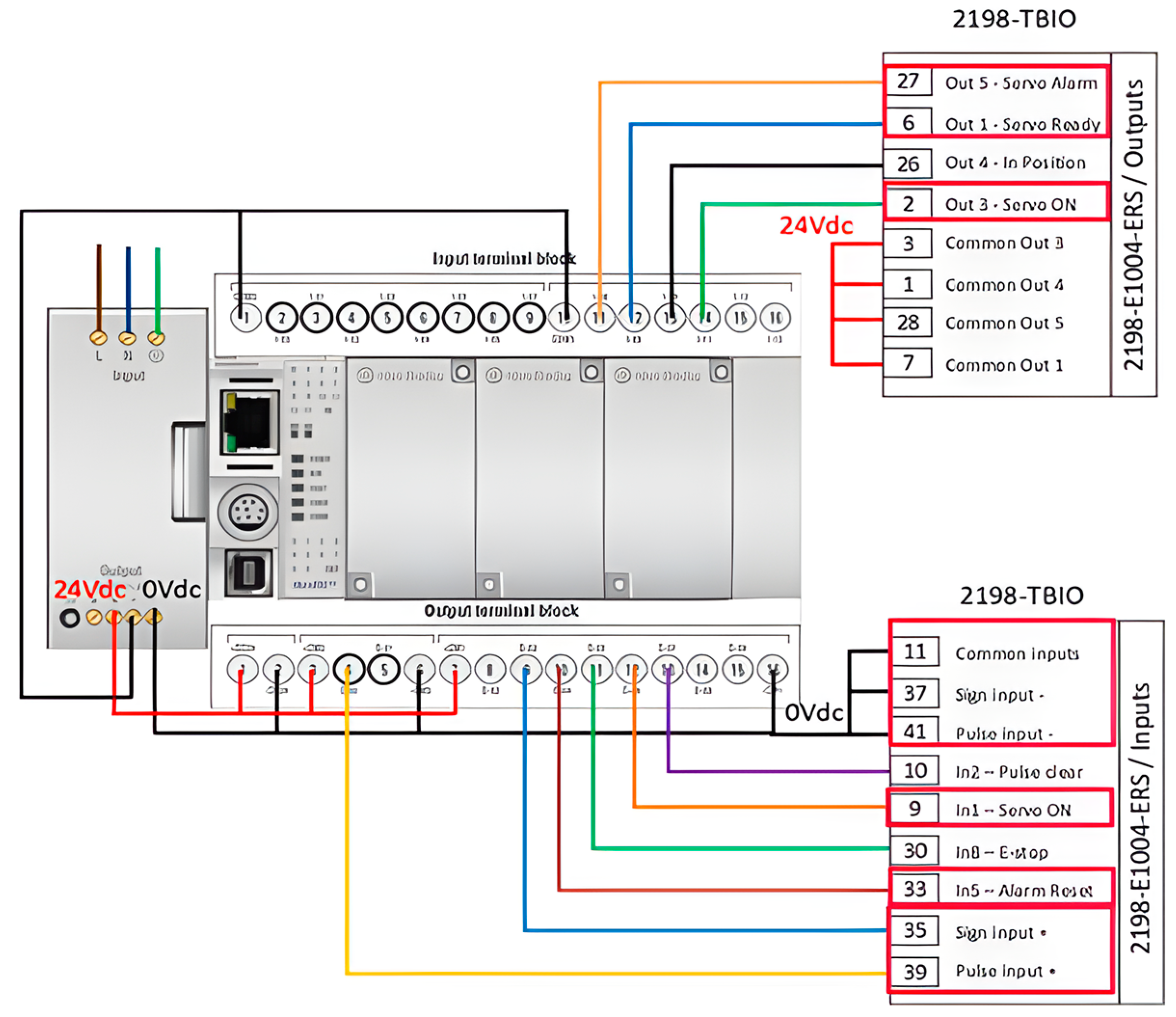
The input power supply to individual devices is realized from a single-phase (230 V) connection through two safety circuit breakers. A 16 A safety circuit breaker was recommended and used for the single-phase power supply for the servo drive converter, and a 2 A safety circuit breaker was sufficient for the connections of the 24 VDC source, which is located directly on the PLC controller due to the small short circuit.
After the input connection of the individual devices to the network, the individual input–output signals were connected between the terminal block of the servo drive and the Allen-Bradley Micro850 PLC controller, according to
Figure 6. A cable labeled H05V-K was used to connect these signals. The blue wires ensure the transfer of information between the servo drive and the PLC controller, and the red and black wires ensure their activity by supplying the network from the 24 VDC source. Subsequently, a switch and an HMI panel were connected from the source, which serves to monitor and enable individual actions of the PLC controller. During the design process, a stand model was created for the PanelView800 HMI panel, which provides a secure attachment to the cabinet sheet.
The Micro850 is compatible with Connected Components Workbench (CCW) software ver. 12, which utilizes reliable Rockwell Automation technology along with Microsoft Visual Studio for advanced programming of controllers and configuration of devices. It also enables data exchange with related products, including HMI control panels and PowerFlex drives. The software offers support for three standard IEC programming languages: ladder diagram, function block diagram, and structured text.
The design and implementation of an intelligent control program are based on two main tasks:
configurations of the Kinetix 5100 servo drive through the KNX5100C software tool,
servomotor motion control configurations using Micro850 controller output pulses.
The configuration of the Kinetix5100 servo drive can be done through the KNX5100C software tool. This software can be used to configure drive parameters, perform auto-tuning, or diagnose the system using the Scope function. The basic function of the servo drive enables users to determine the operating mode of the system. The Kinetix5100 offers enough working mode options to perform different control methods such as position, speed, or torque, with set points being fed from different sources such as Micro850 and Logix via Ethernet/IP or analog and digital inputs to the drive.
Table 1 presents several options for controlling individual inputs and outputs of the servo drive. In this work, the [0×00] PT: Position Control Mode was selected, as the K5100 servo drive will perform servo motor movements based on the input-output signals from the Micro850 PLC device. The other modes offer the possibility of controlling the servomotor via the servo drive and its software program. However, controlling the servomotor only through the servo drive is limited to the index memory, and controlling it via the given software is not very practical.
Furthermore, settings such as the direction of rotation of the servo drive or the electronic gear ratio of the servo drive were added. In this case, the gear ratio was chosen for a representative value of one revolution of the servo drive, i.e., 360°.
The Digital IO feature is utilized to configure the Kinetix5100 servo drive. This feature allows users to set up all necessary digital input-output pulses for the Micro850 controller. Each digital IO can be assigned any function from the available options, and each can be set as either normally closed or normally open.
The actions of the set input–output signals are described in
Table 2.
Configuring the servo drive involves setting the position mode to align with the user-defined parameters in the Micro850 controller upon startup. The sequence of steps for configuring servo motion using the Micro850 controller:
creation and configuration of motion axis and control program in CCW software to manage Kinetix5100 servo motor using Micro850 controller,
creation of a graphic control interface for the PanelView800 HMI display.
Individual variables are located in the main tab of the CCW software, specifically in the Global Variables function. It is possible to open the variable with the tag Axis_REF, where this tag provides important status data about the motion axis. One piece of the data is the AxisState parameter, which provides current information about the state of the axis. Creating the control program itself in the CCW software is possible through structured text, ladder diagrams, or functional block diagrams. The program, shown in
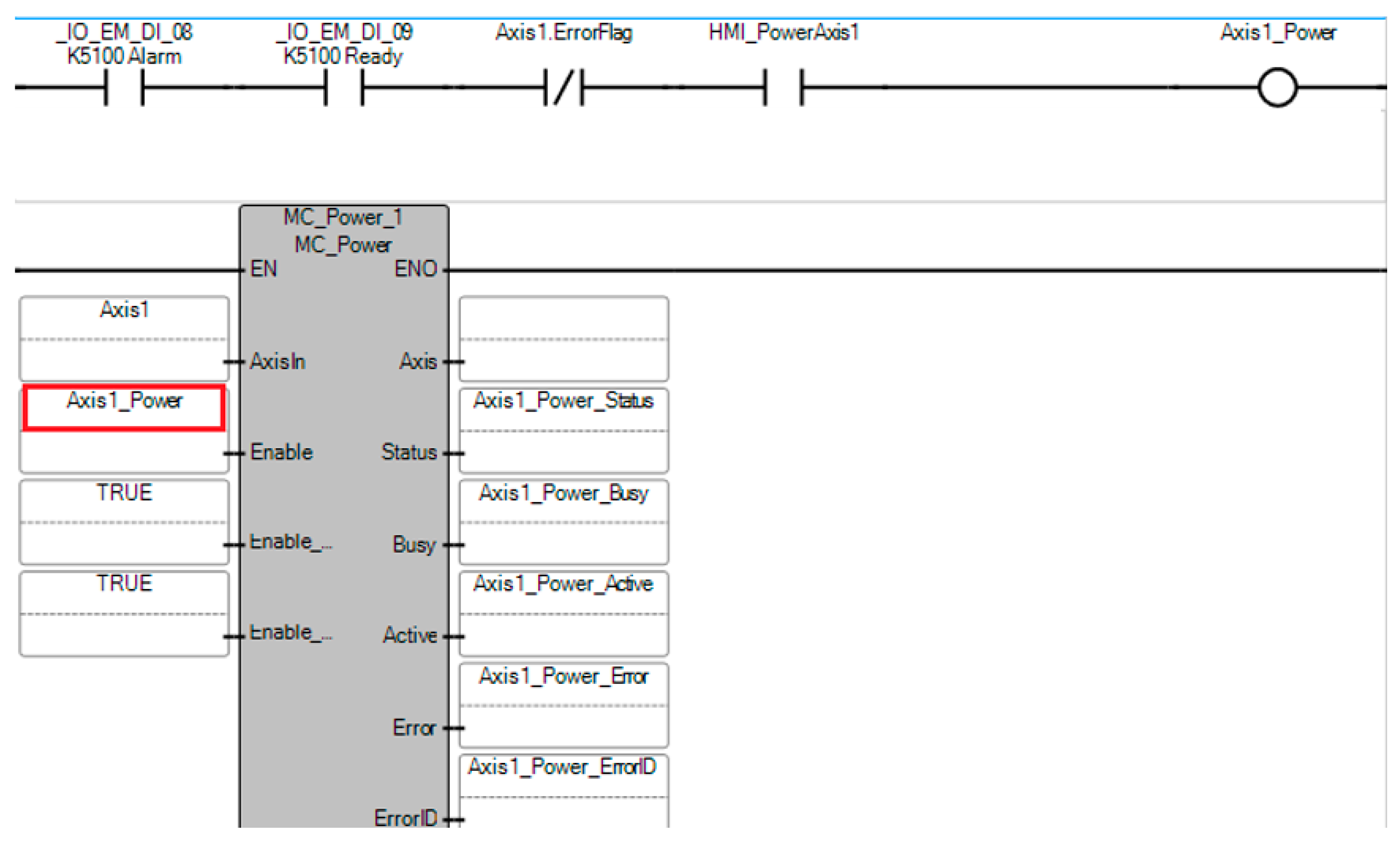
Figure 7, is intended to power the servo drive using the MC_Power instruction. Before powering the servo drive, it is necessary to check its status, ensuring the drive is ready and that the axis does not show any errors. If these requirements are met, the axis can be powered.
Executing the MC_Power instruction invokes the function of powering the motion axis (Servo on), which is sent to the input of the servo drive through a certain output on the terminal board of the PLC device. The function can be started with a previously created logic block or by running the Enable or Execute function directly in the ladder instruction. If the input for the motion axis power function is correctly defined on the servo drive, the servo drive will activate and turn on the servo. In addition, if the Kinetix5100 drive is in the servo-on state, it sends a signal as feedback to the Micro850 controller through its respective output, indicating that the drive is in the servo-on state. If the Micro850 PLC receives this signal, the motion axis will start to be powered, but if it does not receive the signal, then a motion axis error will be generated, which will be shown in the ladder structure, specifically in the Error and ErrodID functions. Therefore, another proposed ladder instruction is MC_Reset, which serves to reset the motion axis error. The motion axis error can only be reset using the MC_Reset instruction or turning off the Micro850 controller.
Table 3 is an overview of the names of the movement instructions used to achieve the individual functions of the servo motor. The names of the motion instructions may vary depending on the selected theme in the CCW software.
An interesting function of the Micro850 device is a movement instruction that guides the movement axis to the starting position. The Micro850 offers five different ways to guide the axis to the starting position. Their descriptions are provided in
Table 4.
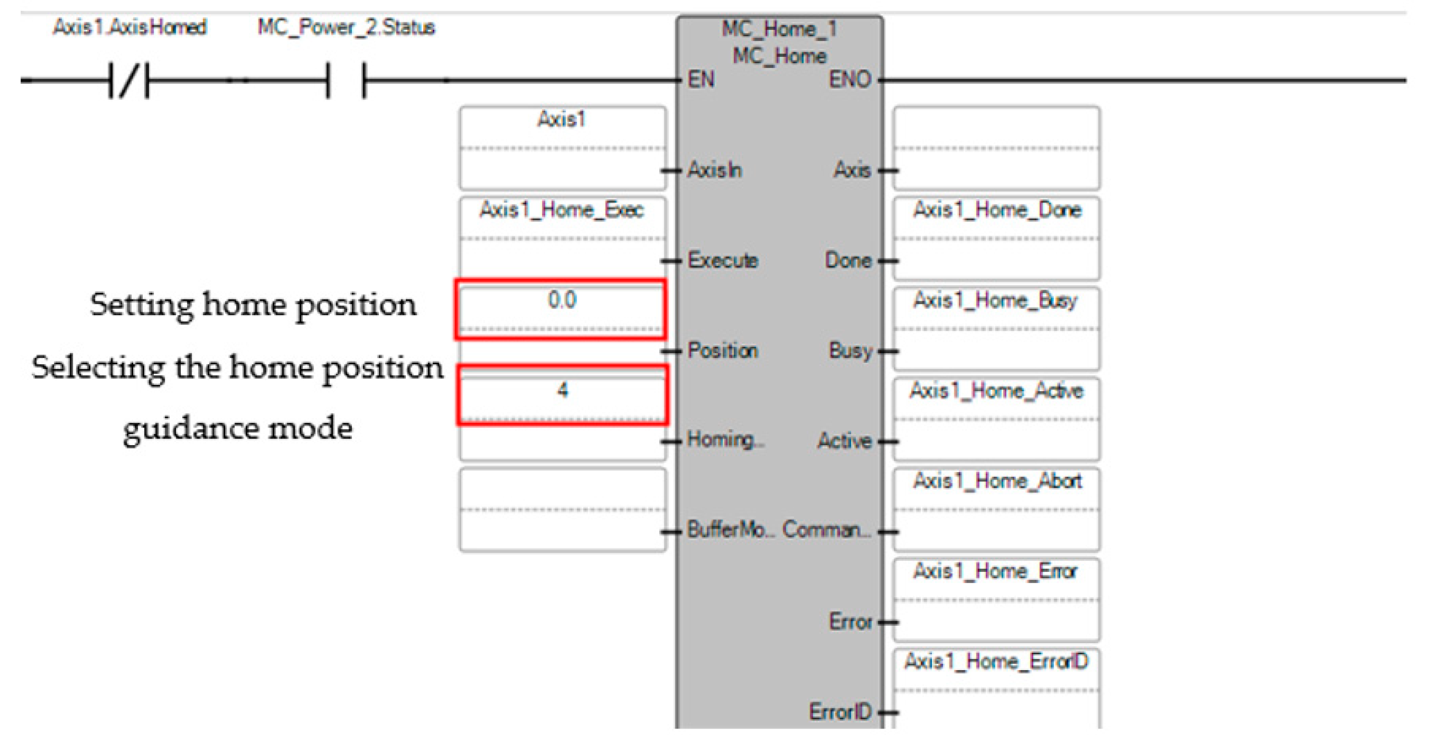
For demonstration purposes, when no homing sensor is connected, mode 0×04 can be used. This mode can be used to set the starting position from the current position of the motion axis. The MC_Home instruction is used for this, with the position set to the value 0. Below the created MC_Home axis starting position instruction, we create the MC_MoveAbsolute absolute movement instruction. This instruction will serve as a button to return to the previously set starting position, i.e., to the value 0. The principle of creating the starting position instruction is shown in
Figure 8.
After the MC_Home function is executed, the motion axis will be set to the home position 0 and the Axis1.AxisHomed value of the Axis_Ref variable will be in the True state. It is this state that ensures the possibility of executing the MC_MoveAbsolute instruction, which serves to move the axis to a specific position, in this case, to the home position of the value 0. This instruction can be executed after entering the input values for position, speed, acceleration, and deceleration, but these values must be greater than 0. Otherwise, a motion axis error will be generated.
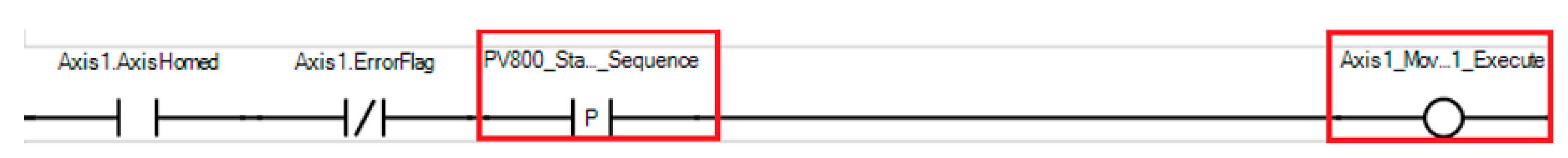
With another multi-block program, a motion sequence was created using the status bits of the motion instructions. This part of motion sequence programming is intended to show how the output bits of a motion instruction can be used to create a motion sequence.
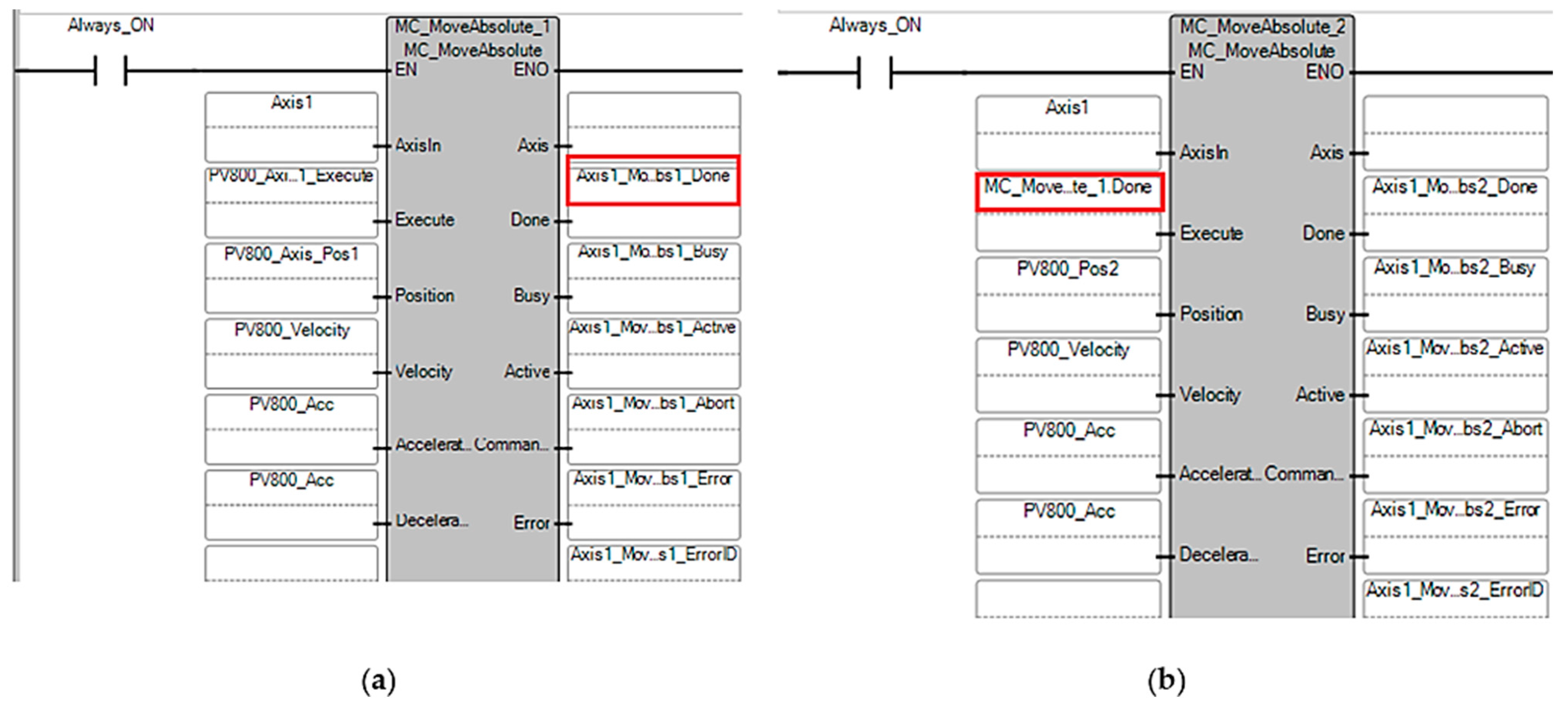
Through two MC_MoveAbsolute instructions, we created a movement between position A and position B. The first movement instruction, MC_MoveAbsolute, is created such that its initiation is performed through the HMI panel by setting the PV800_Start_Squence bit. The instruction can only be executed if the motion axis is at the starting point and the axis shows no motion error. A sample motion sequence is shown in
Figure 9.
After turning on the movement sequence, the movement to the position of the first absolute instruction is performed. Then, the second absolute instruction is set so that after the completion of the positioning of the first absolute instruction, the second absolute instruction is started, and the movement to the second selected position is performed. Specifically, if the first movement is finished, the Done bit of the first movement instruction (MC_MoveAbsolute_1.Done) is used to start the second movement instruction, MC_MoveAbsolute. This principle is presented in
Figure 10.
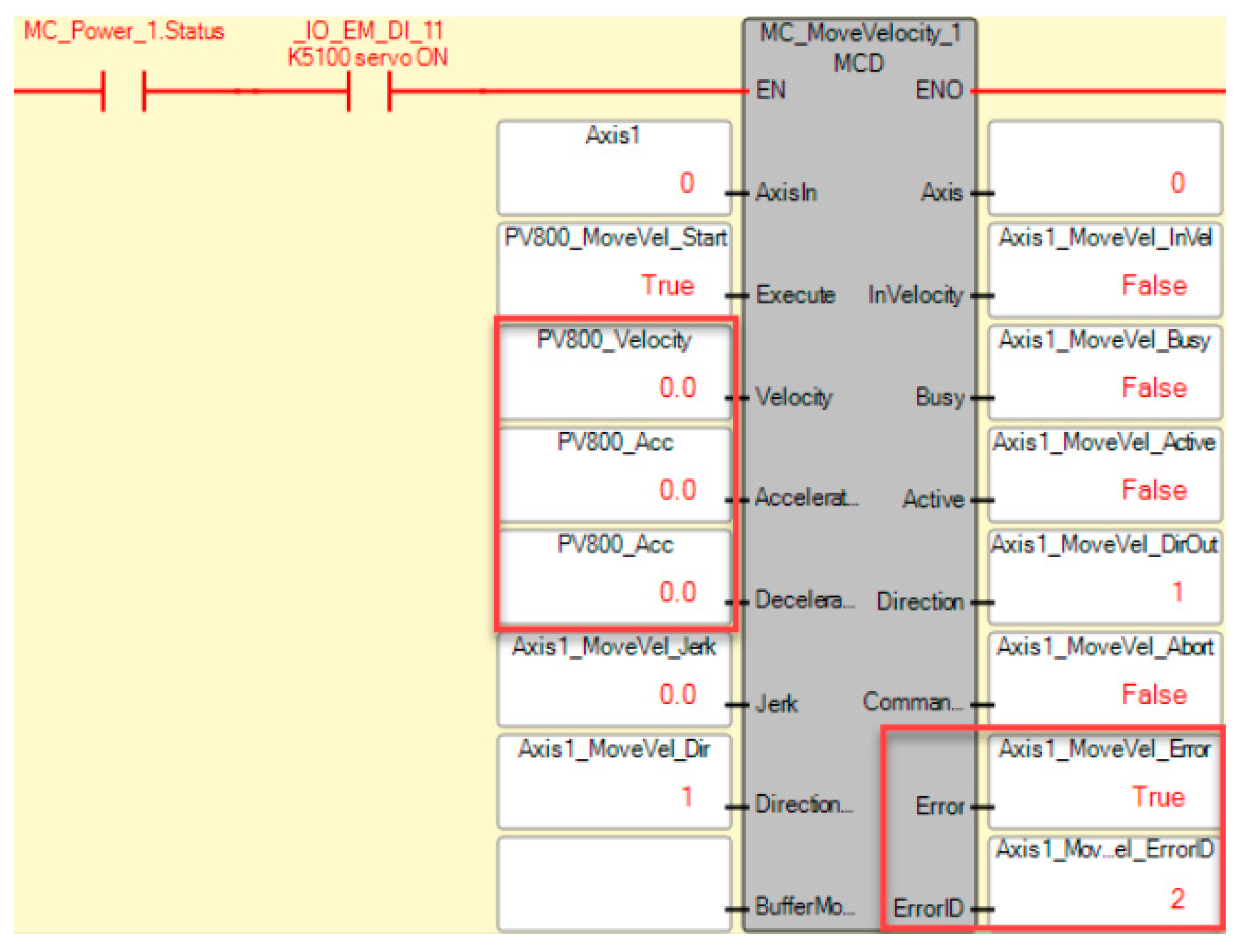
Suppose the motion axis shows an error, the Axis.ErrorFlag bit is set to True. The Axis.ErrorID variable shows information about the given error. The error ID is used to accurately identify the error and provides information on how the given error can be resolved (e.g., motion instruction parameter error, motion axis is in the wrong shape, etc.). Individual information about errors and individual instructions can be found in the help file provided by the CCW software. By clicking on any movement instructions and pressing the F1 shortcut, the CCW program will display a block of information about the given movement instructions. The most common errors include:
ErrorID = 1: This error occurs if the motion axis is not in the correct state. The cause of this error is that a motion instruction was executed while the state of the motion axis equals 7. An axis state of 7 means that the axis has an error. First, before starting any action, the error ErrorID = 1 must first be reset using the MC_Reset instruction; otherwise, movement actions will not be possible. An example of ErrorID1 error generation is shown in
Figure 11.
- 2.
ErrorID = 2: If one or more input parameters are invalid (e.g., poorly defined or outside the allowed limits), the movement instruction will generate an error. An error is also generated if the specified input values for speed, acceleration, and deceleration are set to 0. A zero value for these inputs is not allowed, and the software will generate the error code ErrorID = 2, which is an invalid axis parameter. An example of ErrorID2 error generation is shown in
Figure 12.
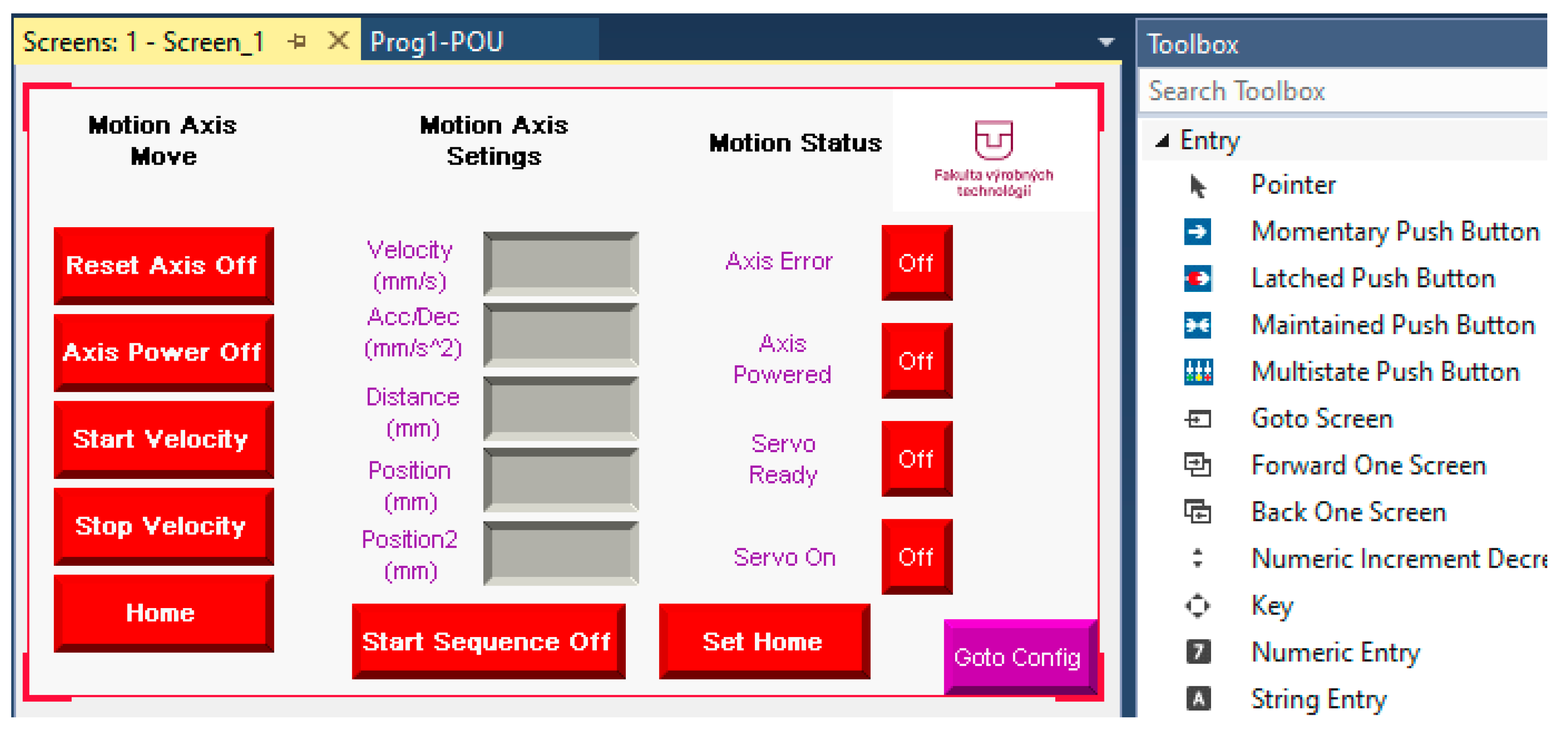
For user control of the designed control program for the servo drive through the HMI panel, it was first necessary to create a graphic display interface that will be used to start individual control steps. It was necessary to add a control panel device to the project created in the CCW software. The panel application can be used to monitor the K5100 servo drive and its current axis status, configure the parameters of motion instructions, or execute motion commands. The panel can be added using the add device button located in the CCW software tree tab. After it is added, its individual functional parts, such as tags, alarms, recipes, and screens, will be displayed in the software.
The software allows users to create their own graphic background in the section of the screen, which will result from the designed control program for the servo drive, as can be seen in
Figure 13. After opening the screenshots section, an empty panel is displayed that allows individual function buttons to be inserted. The CCW software offers a number of functions in the toolbox, from drawing tools to functional buttons or indicators. For individual buttons within the designed control program, it was necessary to create individual connecting tags that correspond to the tags created in the control program. In this case, after opening the tags function, the user will create new tags that will represent individual function buttons. These new tags are assigned in the section of the screen for each trigger button.
In the proposed environment of the HMI display, buttons and fields for inputting the values of the variables were created to control the servomotor via a PLC-controlled servo drive. Important parameters for controlling the servomotor were velocity (mm·s
−1), acceleration (mm·s
−2), distance (mm) and position (mm). During pilot test measurements, the parameters for controlling the X-axis of the movement of the servomotor of the measurement system were determined, as can be seen in
Figure 14. The scan was started by putting the system in the Start Velocity state. After finishing the scanning sequence, the Micro-Epsilon depth sensor returned to the initial position to start a new measurement via the Set Home button. By specifying the value for Position 2, it became possible to control the scanning process in several movement sequences and thus perform repeated scanning passes of the surface of the inspected object.
6. Application of the Measurement System to the Process of Quality Control of Objects
For the proposed control program presented in this article, we decided to apply its use to a measurement system primarily used for measuring and detecting errors in products produced by FDM/FFF 3D printing. By using a control program composed of ladder diagrams, it is possible to easily control the movement of the required movement axes of the designed measuring device structure both clockwise and counterclockwise. In the proposed software solution, it is possible to change the speed and control the movement distance.
The measurement system was designed for detecting errors in objects made with 3D printing technology. Dimensional accuracy verification was performed on the selected scanned object. With the given workplace, it is possible to effectively control objects produced by 3D printing or other production technology and monitor their surface quality, control surface roughness, dimensional accuracy, and material porosity. To verify the functionality of the measuring system, a test sample printed on a commercially available Creality CR-30 3D printer was chosen. This sample was a reduced model of the clutch pedal.
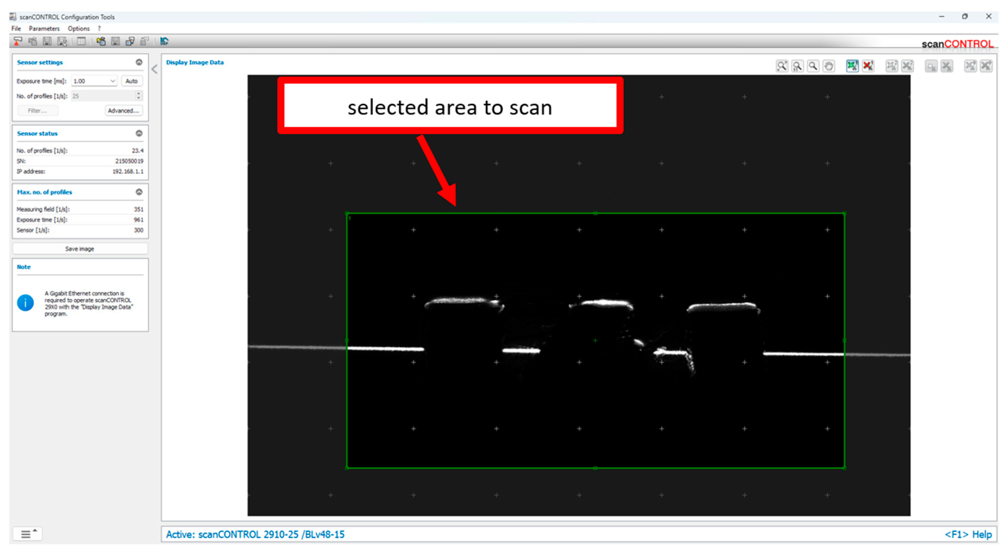
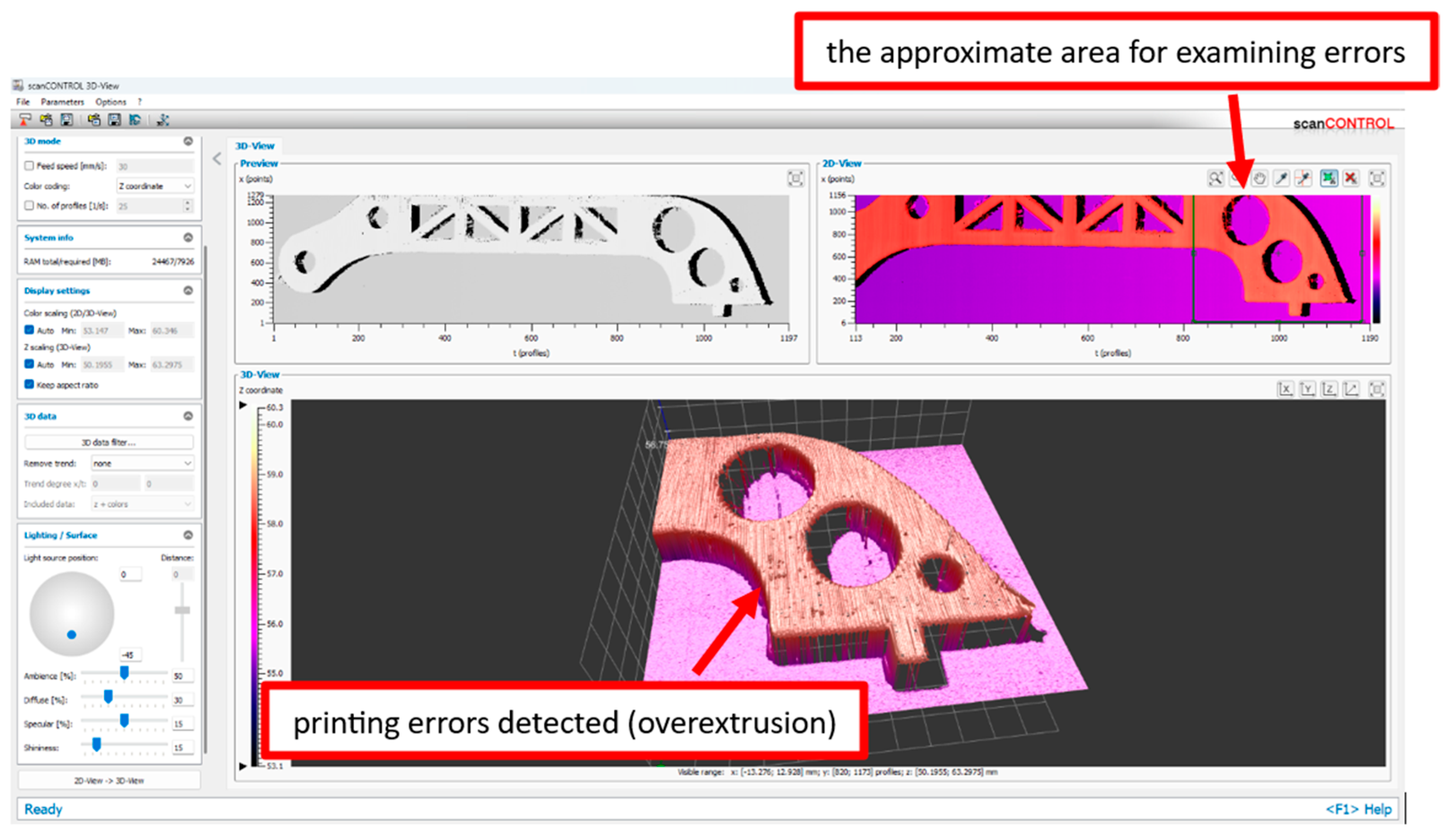
The selected component was checked by connecting the Micro-Epsilon depth sensor to the computer. The next step was to set the depth sensor in the SCANcontrol software, where the scanning speed and the scanned area of the workspace were set. The depth sensor has a scanning range along the Z-axis of 25 mm, while the sensor was positioned 20 mm from the scanned part. Subsequently, the desired speed and distance of movement along the X-axis of the sensor were determined on the HMI touch screen for control using the designed PLC control. The result of the scanning process in the SCANcontrol software, viewed in 2D, can be seen in
Figure 15.
The next step was to save the scanned file in AVI format and load it into the SCAN3Dcontrol software, where the scanning progress was recorded. The software then generated a 3D model of the scanned part. Scanning took place by linear movement along the X-axis of the designed measuring system over the controlled object. On the inspected sample, it was possible to observe errors that arose during the 3D printing production process. These included over extrusion and stringing errors, described in more detail at the beginning of the article as the most frequently occurring errors in FDM 3D printing technology. In
Figure 16, it is possible to observe in more detail in the 3D view the shortcomings of the scanned surface of the test sample in the SCAN3Dcontrol software interface. The volume model of the part obtained in this way can be subjected to several types of measurements for accurate determination of the monitored values. The scanned objects can be generated as an STL file using the software, allowing the obtained 3D object data to be used for reverse engineering purposes.
Comparison of the Created Measuring System with Other Available Scanning Devices
The Creality CR-Scan Raptor ver. 3.3.4 and Creaform Zscanner 700 devices were chosen to compare the results of the proposed scanning system using the Micro-Epsilon depth sensor scanCONTROL BL 25x0-25 with other available scanning device solutions.
The Creality CR-Scan Raptor is a portable scanning device from Creality that combines blue laser light and NIR technology. It allows users to scan objects from 2 to 2000 mm, achieving an accuracy of 0.02 mm. The scanning principle relies on attaching reference points to the scanned object, enabling the scanner to recognize the scanned area. During and after scanning, the Creality Scan ver. 3.3.4 software is used to modify the scanned point cloud. The second scanning device compared was the Zscanner 700, a handheld scanning device that can digitize surfaces and parts in real time. The device has an accuracy of ± 0.05 mm and uses a red laser cross when scanning. Creating a 3D image of objects is based on attaching reference points and gradually traversing the scanned area while the software connects the obtained points. VXelements ver. 11 software was used in the scanning process.
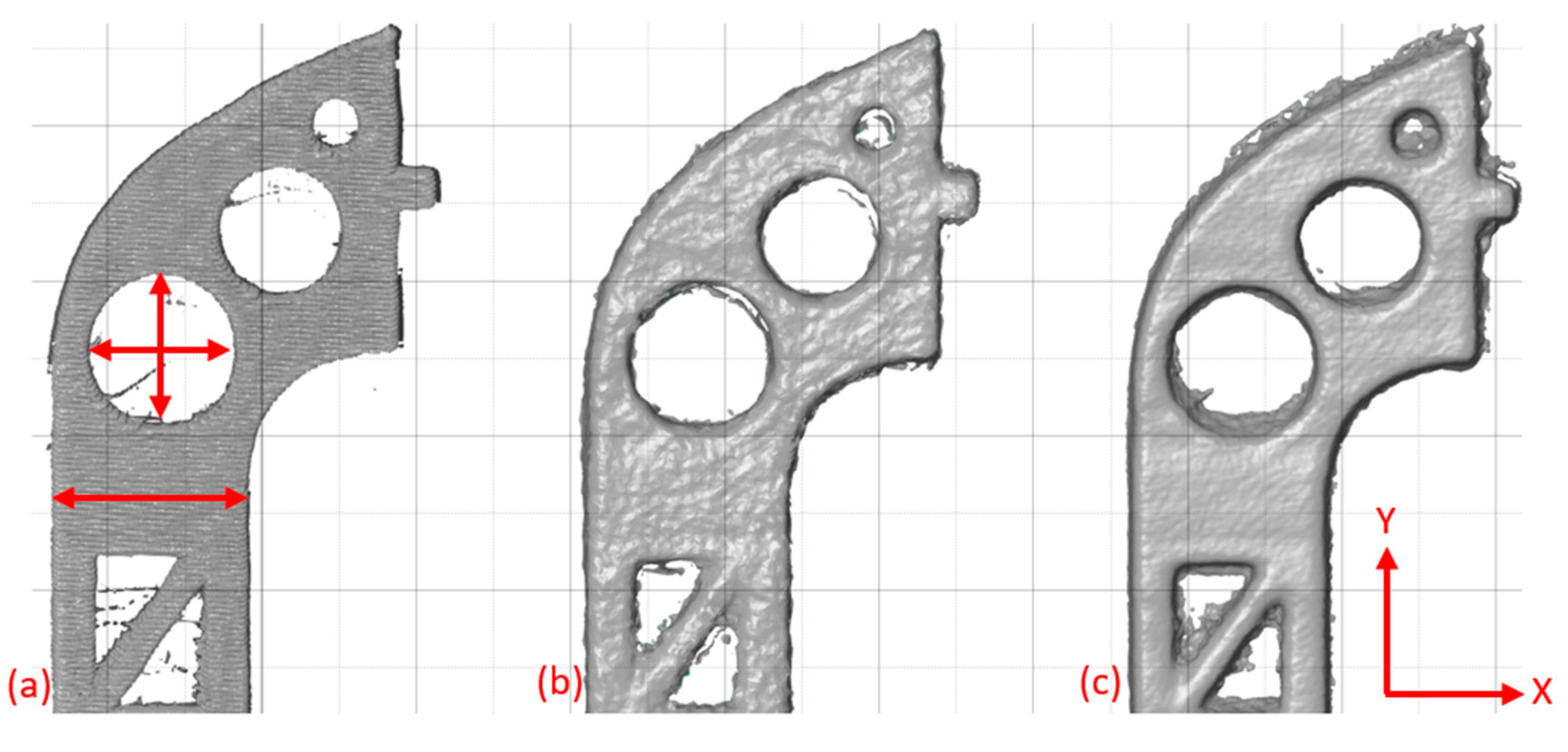
By comparing the created scans in terms of dimensions and surface quality, the desired conclusions were reached. After scanning and creating the “Mesh object”, STL files were generated from each software for dimensional and surface quality control purposes. The GOM Inspect ver. 2018 software was chosen to determine the parameters sought in more detail. This software includes tools for measuring various tolerances or comparing scanned models with reference CAD models. In this measurement, the diameter of the hole and the width of the brake pedal stem were compared as selected parameters, as can be seen in
Figure 17.
The complete processing of the results of the measured values can be seen in
Table 5. It is obvious from the measured values that the accuracy of the scanned objects achieved the best indicators when using the Micro-Epsilon depth sensor.
By comparing the two best-evaluated scanning devices (Micro-Epsilon and Creality Raptor), the percentage differences were calculated, showing that the Micro-Epsilon depth sensor mounted on the created measurement system achieved higher accuracy in the two compared parameters. Compared with the second-best tested scanning device, Creality CR-Raptor, the Micro-Epsilon depth sensor connected to the proposed measurement system achieved better results in the Y-axis by 19.28% and in the stem width by 69.23%.
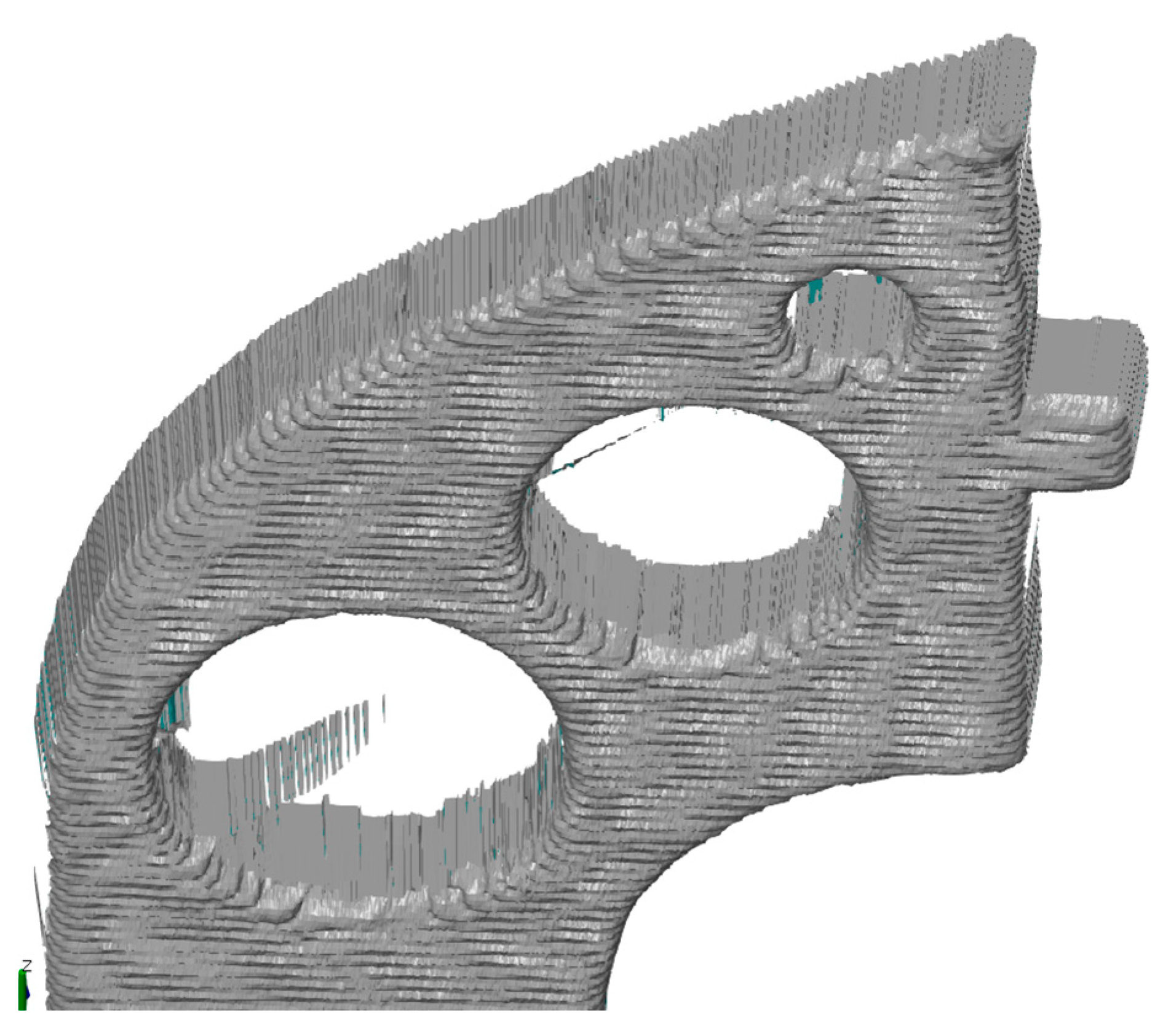
From the comparison, it can be seen that the Micro-Epsilon depth sensor can capture the exact structure of the printed component, allowing observation of basic defects of the object that arose in the additive manufacturing process. For example, on the detail of the test sample presented in
Figure 18, a problem with retraction and a high flow of material created in the production process was detected. With manual scanners, even during more time-consuming scanning, it is impossible to capture and analyze these errors as effectively as with the proposed solution of the measurement system using the Micro-Epsilon depth sensor.
7. Conclusions
Current PLC control systems offer great flexibility, making them suitable for various manufacturing and process control applications. They can operate individual machines and connect them within a system, enhancing productivity and overall efficiency in the plants. The capability of these control units to function effectively under challenging conditions of the industrial sector is a significant benefit for implementing smart manufacturing. Good updating and the availability of powerful devices that support the rapid development of automation also contribute to this.
The aim of this article was to create a measuring system supplemented with a Micro-Epsilon depth sensor. The movement of the sensor on the designed frame provided by a servo motor, is controlled by PLC. The measuring device created in this way will be used to check the accuracy of the surface of components primarily produced by 3D printing technology. For the proposed solution, several trial pilot tests were performed to verify the accuracy of the measurement system with other commercially available solutions used for object scanning.
In order to determine the surface quality and overall homogeneity of the part, it can be concluded from the presented results that the most suitable solution is the Micro-Epsilon depth sensor used in the proposed measuring system with its precise control. On the compared scans with two other selected scanning devices, it is possible to observe a significant inaccuracy of the resulting geometry of the raster compared to the dimension values of the reference CAD model of the brake pedal. Another advantage of using this measurement system is the speed and resulting quality of the scans, without the need for reference marks, as required by commercial scanning devices.
By implementing the created motion control system through the selected engine into the object scanning process, we have confirmed a number of advantages, including:
Operation of the servomotor in both directions according to the specified distance and speed or according to a certain time.
Allowing changes in engine speed even during continuous operation.
Data monitoring and control (current speed, current position, and other operating parameters) through the HMI panel.
The proposed control program can be used in other ways in addition to the application mentioned above. Given the wide range of applications of this PLC-controlled measuring system, we can also mention other options for expanding hardware solutions. For example, expansion I/O modules for the Micro850 controller can be added to handle larger standalone machine applications, contributing to the density and accuracy of analog and digital inputs and outputs as needed. Furthermore, the installation of the control system can be made more efficient by installing sensors, signaling diodes, and push-button switches. Such a solution can simplify the control process and speed up possible reactions to the signaling of malfunctions or collisions.


